G3C100-Pseriesmanual.pdf - Dfi-itox.com
G3C100-Pseriesmanual.pdf - Dfi-itox.com
G3C100-Pseriesmanual.pdf - Dfi-itox.com

You also want an ePaper? Increase the reach of your titles
YUMPU automatically turns print PDFs into web optimized ePapers that Google loves.
<strong>G3C100</strong>-P Series<br />
Rev. A+<br />
System Board<br />
User’s Manual<br />
935-G3C101-000<br />
A81400418
Copyright<br />
This publication contains information that is protected by copyright.<br />
No part of it may be reproduced in any form or by any means or<br />
used to make any transformation/adaptation without the prior<br />
written permission from the copyright holders.<br />
This publication is provided for informational purposes only. The<br />
manufacturer makes no representations or warranties with respect<br />
to the contents or use of this manual and specifically disclaims<br />
any express or implied warranties of merchantability or<br />
fitness for any particular purpose. The user will assume the entire<br />
risk of the use or the results of the use of this document. Further,<br />
the manufacturer reserves the right to revise this publication and<br />
make changes to its contents at any time, without obligation to<br />
notify any person or entity of such revisions or changes.<br />
© 2004. All Rights Reserved.<br />
Trademarks<br />
Windows ® 98, Windows ® 98 SE, Windows ® ME, Windows ® 2000,<br />
Windows NT ® 4.0 and Windows ® XP are registered trademarks<br />
of Microsoft Corporation. VIA is a registered trademark of VIA<br />
Technologies, Inc. Award is a registered trademark of Award Software,<br />
Inc. Other trademarks and registered trademarks of products<br />
appearing in this manual are the properties of their respective<br />
holders.<br />
Caution<br />
To avoid damage to the system:<br />
• Use the correct AC input voltage range.<br />
To reduce the risk of electric shock:<br />
• Unplug the power cord before removing the system chassis<br />
cover for installation or servicing. After installation or servicing,<br />
cover the system chassis before plugging the power cord.
Battery:<br />
• Danger of explosion if battery incorrectly replaced.<br />
• Replace only with the same or equivalent type re<strong>com</strong>mend<br />
by the manufacturer.<br />
• Dispose of used batteries according to the battery manufacturer’s<br />
instructions.<br />
FCC and DOC Statement on Class B<br />
This equipment has been tested and found to <strong>com</strong>ply with the<br />
limits for a Class B digital device, pursuant to Part 15 of the FCC<br />
rules. These limits are designed to provide reasonable protection<br />
against harmful interference when the equipment is operated in a<br />
residential installation. This equipment generates, uses and can radiate<br />
radio frequency energy and, if not installed and used in accordance<br />
with the instruction manual, may cause harmful interference<br />
to radio <strong>com</strong>munications. However, there is no guarantee<br />
that interference will not occur in a particular installation. If this<br />
equipment does cause harmful interference to radio or television<br />
reception, which can be determined by turning the equipment off<br />
and on, the user is encouraged to try to correct the interference<br />
by one or more of the following measures:<br />
• Reorient or relocate the receiving antenna.<br />
• Increase the separation between the equipment and the receiver.<br />
• Connect the equipment into an outlet on a circuit different<br />
from that to which the receiver is connected.<br />
• Consult the dealer or an experienced radio TV technician for<br />
help.<br />
Notice:<br />
1. The changes or modifications not expressly approved by the<br />
party responsible for <strong>com</strong>pliance could void the user's authority<br />
to operate the equipment.<br />
2. Shielded interface cables must be used in order to <strong>com</strong>ply<br />
with the emission limits.
Notice<br />
An electronic file of this manual is included in the CD. To view<br />
the user’s manual in the CD, insert the CD into a CD-ROM drive.<br />
The autorun screen (Main Board Utility CD) will appear. Click<br />
“User’s Manual” on the main menu.
Table of Contents<br />
Chapter 1 - Introduction<br />
1.1 Features and Specifications.................................................................................<br />
1.2 Package Checklist...........................................................................................................<br />
Chapter 2 - Hardware Installation<br />
2.1 System Board Layout ............................................................................................<br />
2.2 System Memory.............................................................................................................<br />
2.3 Jumper Settings.............................................................................................................<br />
2.4 Rear Panel I/O Ports..............................................................................................<br />
2.5 I/O Connectors...........................................................................................................<br />
Chapter 3 - BIOS Setup<br />
3.1 Award BIOS Setup Utility....................................................................................<br />
3.5 Updating the BIOS.......................................................................................................<br />
Chapter 4 - Supported Softwares<br />
7<br />
13<br />
14<br />
15<br />
17<br />
25<br />
35<br />
49<br />
88<br />
4.1 Desktop Management Interface.................................................................... 90<br />
4.2 Drivers, Utilities and Software Applications.................................... 93<br />
4.3 Installation Notes........................................................................................................... 102
1<br />
Introduction<br />
Appendix A - Watchdog Timer<br />
A.1 Watchdog Timer......................................................................................................... 103<br />
Appendix B - Using the Suspend to RAM<br />
Function<br />
B1<br />
Using the Suspend to RAM Function..................................................<br />
104<br />
Appendix C - System Error Messages<br />
C.1 POST Beep.....................................................................................................................<br />
C.2 Error Messages............................................................................................................<br />
Appendix D - Troubleshooting<br />
108<br />
108<br />
D.1 Troubleshooting Checklist.................................................................................<br />
110<br />
6
Chapter 1 - Introduction<br />
1.1 Features and Specifications<br />
1.1.1 Features<br />
Chipset<br />
Introduction<br />
1<br />
• VIA ® CLE266 and VT8235<br />
- VIA ® CLE266 (VT8623) north bridge with integrated AGP<br />
graphic core<br />
- VIA ® VT8235 south bridge<br />
Processor<br />
• VIA ® C3 up to 1.2GHz processor (EBGA packaged)<br />
• VIA ® Eden up to 1GHz low power processor (EBGA packaged)<br />
System Memory<br />
• Two 184-pin DDR SDRAM DIMM socket<br />
• 2.5V unbuffered PC1600 (DDR200) or PC2100 (DDR266)<br />
DDR SDRAM DIMM<br />
• Supports up to 2GB system memory using 64Mbit, 128Mbit,<br />
256Mbit or 512Mbit x8/x16 technology<br />
Expansion Slots<br />
• 1 PCI slot for PCI expansion card or customized riser card for 1,<br />
2 or 3 PCI slots expansion (for low profile PCI card only)<br />
Onboard Graphics Features<br />
• Graphics memory<br />
- Shares 16M/32M/64M frame buffer of the system memory<br />
- Optimized Share Memory Architecture (SMA)<br />
• Graphics controller<br />
- 133MHz for internal graphic engine clock<br />
- Integrated 250MHz DAC<br />
- Microsoft ® DriectX 7.0 and 8.0 <strong>com</strong>pensation<br />
- High quality texture filter modes: nearest, linear, bi-linear and<br />
anisotropic<br />
7
1<br />
Introduction<br />
- Hardware MPEG2 decode engine<br />
- Supports CRT with resolution up to 1920x1440 @ 60Hz<br />
refresh<br />
- 3M triangles/sec setup engine<br />
• Software drivers<br />
- Windows ® 98SE/2000/ME/XP<br />
- Windows NT ® 4.0<br />
Extensive Display Support<br />
• Direct TFT flat panel interface up to 24-bit data width; supports<br />
18, 24 or 18+18 TFT panel with LVDS encoders<br />
• Supports TFT panel with resolution up to 1600x1200<br />
Onboard Audio Features<br />
• AC'97 supported with full duplex, independent sample rate converter<br />
for audio recording and playback<br />
• Standard AC'97 version 2.1<br />
• Supports Microsoft ® DirectSound<br />
• 2-channel audio output<br />
Onboard LAN Features<br />
• VIA VT6103 ethernet Phy controller<br />
• Single chip 100Base-TX/10Base-T Physical Layer Solution<br />
• MII interface to ethernet controller<br />
• 10/100 auto sensing<br />
• IEEE 802.3 and 10BASE-T/100BASE-TX <strong>com</strong>pliant physical<br />
layer interface<br />
• IEEE 802.3u auto-negotiation<br />
Compatibility<br />
• PCI 2.2 and AC ’97 <strong>com</strong>pliant<br />
IDE Interface<br />
• Supports ATA/33, ATA/66, ATA/100 and ATA/133 hard drives<br />
• PIO Mode 4 Enhanced IDE (data transfer rate up to 16.6MB/<br />
sec.)<br />
8
Introduction<br />
1<br />
IrDA Interface<br />
The system board is equipped with an IrDA connector for wireless<br />
connectivity between your <strong>com</strong>puter and peripheral devices. The<br />
IRDA (Infrared Data Association) specification supports data<br />
transfers of 115K baud at a distance of 1 meter.<br />
USB Connectors<br />
The system board supports USB 2.0 and USB 1.1 connectors.<br />
USB 1.1 supports 12Mb/second bandwidth while USB 2.0 supports<br />
480Mb/second bandwidth providing a marked improvement<br />
in device transfer speeds between your <strong>com</strong>puter and a<br />
wide range of simultaneously accessible external Plug and Play<br />
peripherals.<br />
BIOS<br />
• Award BIOS, Windows ® 98SE/2000/ME/XP Plug and Play<br />
<strong>com</strong>patible<br />
• Supports SCSI sequential boot-up<br />
• Supports DMI 2.0 function<br />
• 2Mbit flash memory<br />
• Supports TFT panel BIOS core<br />
Desktop Management Interface (DMI)<br />
The system board <strong>com</strong>es with a DMI 2.0 built into the BIOS. The<br />
DMI utility in the BIOS automatically records various information<br />
about your system configuration and stores these information in<br />
the DMI pool, which is a part of the system board's Plug and Play<br />
BIOS. DMI, along with the appropriately networked software, is<br />
designed to make inventory, maintenance and troubleshooting of<br />
<strong>com</strong>puter systems easier. Refer to chapter 4 for instructions on<br />
using the DMI utility.<br />
9
1<br />
Introduction<br />
Rear Panel I/O Ports<br />
• 1 mini-DIN-6 PS/2 mouse port<br />
• 1 mini-DIN-6 PS/2 keyboard port<br />
• 3 DB-9 serial ports<br />
• 1 DB-15 VGA port<br />
• 1 RJ45 LAN port<br />
• 4 USB 2.0/1.1 ports<br />
• 3 audio jacks: mic-in, line-in and speaker-out<br />
I/O Connectors<br />
• 1 connector for 2 additional external USB 2.0/1.1 ports<br />
• 1 LVDS LCD panel connector<br />
• 1 LCD/Inverter power connector<br />
• 1 connector for 1 external serial port<br />
• 1 front audio connector for speaker-out and mic-in jacks<br />
• 1 CD-in internal audio connector<br />
• 1 S/PDIF-out connector<br />
• 1 connector for IrDA interface<br />
• 1 parallel connector<br />
• 1 40-pin IDE 1 connector for 3.5" HDD<br />
• 1 44-pin IDE 2 connector for 2.5" HDD (2.0 pitch)<br />
• 1 floppy connector (FPC connector type)<br />
• 1 ATX power supply connector<br />
• 2 fan connectors<br />
1.1.2 System Health Monitor Functions<br />
The system board is capable of monitoring the following “system<br />
health” conditions.<br />
• Monitors CPU/system temperature<br />
• Monitors CPU/VCC3/5V/12V/VBAT/5VSB voltages<br />
• Monitors CPU fan and chassis fan speed<br />
• Read back capability that displays temperature, voltage and fan<br />
speed<br />
10
Introduction<br />
1<br />
1.1.3 Intelligence<br />
Watchdog Timer<br />
The Watchdog Timer function allows your application to regularly<br />
“clear” the system at the set time interval. If the system hangs or<br />
fails to function, it will reset at the set time interval so that your<br />
system will continue to operate.<br />
Dual Function Power Button<br />
Depending on the setting in the “Soft-Off By PWRBTN” field of the<br />
Power Management Setup, this switch will allow the system to enter<br />
the Soft-Off or Suspend mode.<br />
Wake-On-Ring<br />
This feature allows the system that is in the Suspend mode or Soft<br />
Power Off mode to wake-up/power-on to respond to calls <strong>com</strong>ing<br />
from an external modem or respond to calls from a modem PCI<br />
card that uses the PCI PME (Power Management Event) signal to<br />
remotely wake up the PC.<br />
Important:<br />
If you are using a modem add-in card, the 5VSB power source<br />
of your power supply must support a minimum of ≥720mA.<br />
Wake-On-LAN<br />
This feature allows the network to remotely wake up a Soft<br />
Power Down (Soft-Off) PC. It is supported via a PCI LAN card<br />
that uses the PCI PME (Power Management Event) signal. However,<br />
if your system is in the Suspend mode, you can power-on<br />
the system only through an IRQ or DMA interrupt.<br />
Important:<br />
The 5VSB power source of your power supply must support<br />
≥720mA.<br />
11
1<br />
Introduction<br />
Wake-On-PS/2 Keyboard/Mouse<br />
This function allows you to use the PS/2 keyboard or PS/2 mouse<br />
to power-on the system.<br />
Important:<br />
The 5VSB power source of your power supply must support<br />
≥720mA.<br />
Wake-On-USB Keyboard<br />
This function allows you to use a USB keyboard to wake up a<br />
system from the S3 (STR - Suspend To RAM) state.<br />
Important:<br />
• If you are using the Wake-On-USB Keyboard function for 2<br />
USB ports, the 5VSB power source of your power supply<br />
must support ≥1.5A.<br />
• If you are using the Wake-On-USB Keyboard function for 3<br />
or more USB ports, the 5VSB power source of your power<br />
supply must support ≥2A.<br />
RTC Timer to Power-on the System<br />
The RTC installed on the system board allows your system to<br />
automatically power-on on the set date and time.<br />
ACPI STR<br />
The system board is designed to meet the ACPI (Advanced Configuration<br />
and Power Interface) specification. ACPI has energy saving<br />
features that enables PCs to implement Power Management<br />
and Plug-and-Play with operating systems that support OS Direct<br />
Power Management. Currently, only Windows ® 98/2000/ME/XP<br />
supports the ACPI function. ACPI when enabled in the Power Management<br />
Setup will allow you to use the Suspend to RAM function.<br />
With the Suspend to RAM function enabled, you can power-off the<br />
system at once by pressing the power button or selecting “Standby”<br />
when you shut down Windows ® 98/2000/ME/XP without having to<br />
go through the sometimes tiresome process of closing files,<br />
applications and operating system. This is because the system is<br />
capable of storing all programs and data files during the entire<br />
12
Introduction<br />
1<br />
operating session into RAM (Random Access Memory) when it<br />
powers-off. The operating session will resume exactly where you left<br />
off the next time you power-on the system.<br />
Important:<br />
The 5VSB power source of your power supply must support<br />
≥1A.<br />
Virus Protection<br />
Most viruses today destroy data stored in hard drives. The system<br />
board is designed to protect the boot sector and partition table<br />
of your hard disk drive.<br />
1.2 Package Checklist<br />
The system board package contains the following items:<br />
! The system board<br />
! A user’s manual<br />
! One IDE cable<br />
! One “Main Board Utility” CD<br />
If any of these items are missing or damaged, please contact your<br />
dealer or sales representative for assistance.<br />
13
2 Hardware Installation<br />
Chapter 2 - Hardware Installation<br />
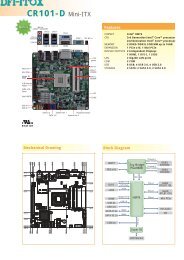
2.1 System Board Layout<br />
CPU fan 1<br />
DDR 1 DDR 2<br />
KB<br />
Mouse<br />
1<br />
2<br />
COM 2 RS232/AUX<br />
select (JP1)<br />
12<br />
COM 4 RS232/485/<br />
DIMM Standby<br />
Power LED<br />
ATX<br />
power<br />
COM 1<br />
COM 2<br />
1<br />
AUX select (JP2)<br />
11<br />
1<br />
COM 4<br />
Fintek<br />
F81216D<br />
VIA<br />
C3 Eden<br />
1<br />
IrDA<br />
COM 3<br />
VGA<br />
LVDS LCD panel<br />
LCD power select<br />
(JP6)<br />
1<br />
VIA<br />
CLE266<br />
1<br />
USB 4<br />
USB 3<br />
LAN<br />
USB 2<br />
USB 1<br />
Mic-in<br />
Line-in<br />
Line-out<br />
1<br />
1<br />
1<br />
USB 1-4<br />
power (JP3)<br />
1<br />
CD-in<br />
1<br />
S/PDIF<br />
Front audio<br />
LAN<br />
Phy<br />
1<br />
LCD brightness<br />
control (JP4)<br />
1<br />
LCD/Inverter power<br />
1<br />
1<br />
BIOS<br />
Battery<br />
LCD brightness<br />
power (JP5)<br />
1<br />
USB 5-6 power (JP8)<br />
FDD<br />
1<br />
USB 5-6<br />
1<br />
Clear CMOS<br />
(JP7)<br />
Parallel<br />
PCI slot<br />
1<br />
VIA<br />
VT8235<br />
VIA<br />
VT8235<br />
Chassis fan<br />
IDE 2<br />
1<br />
IDE 1<br />
1<br />
1 Front<br />
panel<br />
1<br />
14
.<br />
.<br />
.<br />
.<br />
.<br />
.<br />
.<br />
.<br />
Hardware Installation<br />
2<br />
Warning:<br />
Electrostatic discharge (ESD) can damage your system board, processor,<br />
disk drives, add-in boards, and other <strong>com</strong>ponents. Perform the<br />
upgrade instruction procedures described at an ESD workstation only.<br />
If such a station is not available, you can provide some ESD<br />
protection by wearing an antistatic wrist strap and attaching it to a<br />
metal part of the system chassis. If a wrist strap is unavailable,<br />
establish and maintain contact with the system chassis throughout<br />
any procedures requiring ESD protection.<br />
2.2 System Memory<br />
DDR 1<br />
DDR 2<br />
VIA<br />
VT8235<br />
The system board supports DDR SDRAM DIMM. Double Data<br />
Rate SDRAM (DDR SDRAM) is a type of SDRAM that doubles the<br />
data rate through reading and writing at both the rising and falling<br />
edge of each clock. This effectively doubles the speed of operation<br />
therefore doubling the speed of data transfer.<br />
BIOS Setting<br />
Configure the memory in the Advanced Chipset Features submenu<br />
(“DRAM Clock/Drive Control” section) of the BIOS.<br />
15
2 Hardware Installation<br />
2.2.1 Installing the DIM Module<br />
A DIM module simply snaps into a DIMM socket on the system<br />
board. Pin 1 of the DIM module must correspond with Pin 1 of the<br />
socket.<br />
Notch<br />
Key<br />
Tab<br />
Tab<br />
Pin 1<br />
1. Pull the “tabs” which are at the ends of the socket to the side.<br />
2. Position the DIMM above the socket with the “notch” in the<br />
module aligned with the “key” on the socket.<br />
3. Seat the module vertically into the socket. Make sure it is<br />
<strong>com</strong>pletely seated. The tabs will hold the DIMM in place.<br />
16
2.3 Jumper Settings<br />
2.3.1 Clear CMOS Data<br />
Hardware Installation<br />
2<br />
VIA<br />
VT8235<br />
JP7<br />
!<br />
3<br />
2<br />
1<br />
1-2 On: Normal<br />
(default)<br />
3<br />
2<br />
1<br />
2-3 On:<br />
Clear CMOS Data<br />
If you encounter the following,<br />
a) CMOS data be<strong>com</strong>es corrupted.<br />
b) You forgot the keyboard, supervisor or user password.<br />
c) You are unable to boot-up the <strong>com</strong>puter system because the<br />
processor’s ratio was incorrectly set in the BIOS.<br />
you can reconfigure the system with the default values stored in the<br />
ROM BIOS.<br />
To load the default values stored in the ROM BIOS, please follow<br />
the steps below.<br />
1. Power-off the system and unplug the power cord.<br />
2. Set JP7 pins 2 and 3 to On. Wait for a few seconds and set JP7<br />
back to its default setting, pins 1 and 2 On.<br />
3. Now plug the power cord and power-on the system.<br />
If your reason for clearing the CMOS data is due to incorrect<br />
setting of the processor’s ratio/clock in the BIOS, please proceed<br />
to step 4.<br />
17
2 Hardware Installation<br />
4. After powering-on the system, press to enter the main<br />
menu of the BIOS.<br />
5. Select the Frequency/Voltage Control submenu and press .<br />
6. Set the “VIA C3 Clock Ratio” field to its default setting or an<br />
appropriate frequency ratio. Refer to the Frequency/Voltage<br />
Control section in chapter 3 for more information.<br />
7. Press to return to the main menu of the BIOS setup<br />
utility. Select “Save & Exit Setup” and press .<br />
8. Type and press .<br />
18
Hardware Installation<br />
2<br />
2.3.2 USB Power Select<br />
VIA<br />
VT8235<br />
USB 5-6<br />
(JP8)<br />
!<br />
1 2<br />
3<br />
1-2 On:<br />
VCC +5V<br />
(default)<br />
1 2<br />
3<br />
2-3 On:<br />
5V Standby<br />
USB 1-4<br />
(JP3)<br />
!<br />
3<br />
2<br />
1<br />
1-2 On:<br />
VCC +5V<br />
(default)<br />
3<br />
2<br />
1<br />
2-3 On:<br />
5V Standby<br />
JP3 (for USB 1-4) and JP8 (for USB 5-6) are used to select the<br />
power of the USB ports. Selecting 5V Standby will allow you to use<br />
the USB keyboard to wake up the system.<br />
BIOS Setting:<br />
“USB Resume From S3” in the Power Management Setup submenu<br />
(“IRQ/Event Activity Detect” section) of the BIOS must be set to<br />
Enabled. Refer to chapter 3 for more information.<br />
Important:<br />
• If you are using the Wake-On-USB Keyboard function for 2<br />
USB ports, the 5VSB power source of your power supply<br />
must support ≥1.5A.<br />
• If you are using the Wake-On-USB Keyboard function for 3<br />
or more USB ports, the 5VSB power source of your power<br />
supply must support ≥2A.<br />
19
2 Hardware Installation<br />
VIA<br />
VT8235<br />
JP6<br />
1 2 3<br />
1 2 3<br />
!<br />
1-2 On: VCC 2-3 On: VCC3<br />
(default)<br />
2.3.3 LCD Panel Power Select<br />
JP6 is used to select the power supplied to the LCD panel.<br />
20
Hardware Installation<br />
2<br />
2.3.4 LCD Brightness Power Select<br />
VIA<br />
VT8235<br />
JP5<br />
1 2 3<br />
1 2 3<br />
!<br />
1-2 On: VCC 2-3 On: VCC3<br />
(default)<br />
JP5 is used to select the power for the LCD’s brightness.<br />
21
JP4<br />
!<br />
3 1<br />
1-2: Increases the voltage level<br />
2-3: Decreases the voltage level<br />
2 Hardware Installation<br />
VIA<br />
VT8235<br />
2.3.5 LCD Brightness Control (Voltage Level Adjust)<br />
JP4 must be connected to the LCD Brightness Control button of<br />
the LCD Display Panel. It is used to adjust the brightness of the<br />
LCD Display Panel. Increasing or decreasing the voltage to control<br />
the LCD panel’s brightness varies among Inverters. You must refer to<br />
the Inverter’s specification to make the appropriate adjustment to<br />
the brightness of the LCD panel.<br />
22
2.3.6 COM 2’s RS232/AUX Select<br />
Hardware Installation<br />
2<br />
JP1<br />
!<br />
2 4 6<br />
2 4 6<br />
1 3 5<br />
1-3, 2-4 On:<br />
RS232<br />
(default)<br />
1 3 5<br />
3-5 (5V),<br />
4-6 (12V) On:<br />
Auxiliary power<br />
VIA<br />
VT8235<br />
COM 2 is an RS-232 port. If the serial device connected to this<br />
port requires auxiliary power from the system board, set JP1 pins<br />
3-5 and 4-6 to On. Otherwise, leave this jumper’s setting at 1-3, 2-4<br />
On.<br />
23
2 Hardware Installation<br />
VIA<br />
VT8235<br />
2.3.7 COM 4’s RS232/RS485/AUX Select<br />
JP2<br />
!<br />
2<br />
1<br />
12<br />
11<br />
2<br />
12<br />
2<br />
12<br />
2<br />
12<br />
1<br />
11<br />
1-3, 2-4, 7-9, 8-10 On:<br />
RS232<br />
(default)<br />
1<br />
11<br />
3-5, 4-6, 7-9, 8-10 On:<br />
RS485<br />
1<br />
11<br />
9-11 (12V),<br />
10-12 (5V) On:<br />
Auxiliary power<br />
JP2 is used to set COM 4 to RS-232 or RS-485. If the serial device<br />
connected to this port requires auxiliary power from the system<br />
board, set JP2 pins 9-11 and 10-12 to On. This setting automatically<br />
sets COM 4 at RS-232.<br />
24
Hardware Installation<br />
2<br />
2.4 Rear Panel I/O Ports<br />
PS/2<br />
Mouse<br />
COM 1 COM 3<br />
LAN<br />
Mic-in<br />
USB 4<br />
Line-in<br />
Speaker-out<br />
PS/2<br />
K/B<br />
COM 2 VGA USB 1-2 USB 3<br />
The rear panel I/O ports consist of the following:<br />
• PS/2 mouse port<br />
• PS/2 keyboard port<br />
• 3 COM ports<br />
• VGA port<br />
• LAN port<br />
• USB ports<br />
• Mic-in jack<br />
• Line-in jack<br />
• Speaker-out jack<br />
25
.<br />
.<br />
.<br />
.<br />
.<br />
.<br />
.<br />
.<br />
2 Hardware Installation<br />
2.4.1 PS/2 Mouse and PS/2 Keyboard Ports<br />
VIA<br />
PS/2 Mouse<br />
"<br />
PS/2 Keyboard<br />
VT8235<br />
The system board is equipped with an onboard PS/2 mouse<br />
(Green) and PS/2 keyboard (Purple) ports - both at location CN1<br />
of the system board. The PS/2 mouse port uses IRQ12. If a mouse<br />
is not connected to this port, the system will reserve IRQ12 for<br />
other expansion cards.<br />
Warning:<br />
Make sure to turn off your <strong>com</strong>puter prior to connecting or<br />
disconnecting a mouse or keyboard. Failure to do so may<br />
damage the system board.<br />
Wake-On-PS/2 Keyboard/Mouse<br />
The Wake-On-PS/2 Keyboard/Mouse function allows you to use the<br />
PS/2 keyboard or PS/2 mouse to power-on the system. To use this<br />
function:<br />
• BIOS Setting:<br />
Configure the PS/2 wake up function in the Power Management<br />
Setup submenu (“IRQ/Event Activity Detect” section) of the<br />
BIOS. Refer to chapter 3 for more information.<br />
Important:<br />
The 5VSB power source of your power supply must support<br />
≥720mA.<br />
26
Hardware Installation<br />
2<br />
2.4.2 Serial Ports<br />
COM 1<br />
COM 2<br />
COM 3<br />
"<br />
"<br />
9<br />
COM 4<br />
RI<br />
RTS<br />
SG<br />
TD<br />
CD<br />
1<br />
2<br />
"<br />
VIA<br />
VT8235<br />
CTS<br />
DSR<br />
DTR<br />
RD<br />
The system board is equipped with 3 onboard serial ports at<br />
locations CN4 (COM 1 and COM 2) and CN6 (COM 3). It is also<br />
equipped with a 9-pin connector at location CN7 for COM 4. These<br />
serial ports are RS-232 and/or RS-485 asynchronous <strong>com</strong>munication<br />
ports with 16C550A-<strong>com</strong>patible UARTs that can be used with<br />
modems, serial printers, remote display terminals, and other serial<br />
devices.<br />
To connect COM 4, please refer to the following description. The<br />
serial port may be mounted on a card-edge bracket. Install the cardedge<br />
bracket to the system chassis then insert the cable connector<br />
to CN7. Make sure the colored stripe on the ribbon cable is aligned<br />
with pin 1 of CN7.<br />
Important:<br />
If the LCD Display Panel that is connected to the LVDS LCD<br />
Panel connector supports touch screen, DO NOT connect a<br />
serial device to COM 3 because the touch screen function is<br />
internally connected to COM 3.<br />
27
2 Hardware Installation<br />
Jumper Setting<br />
If the serial device connected to COM 2 and/or COM 4 requires<br />
auxiliary power from the system board, set JP1 and/or JP2<br />
appropriately. Refer to “COM 2’s RS232/AUX Select” and “COM 4’s<br />
RS232/RS485/AUX Select” in this chapter for more information.<br />
BIOS Setting<br />
Select the serial ports’ I/O address in the Integrated Peripherals<br />
submenu (“Super IO Device” section) of the BIOS. Refer to chapter<br />
3 for more information.<br />
28
Hardware Installation<br />
2<br />
2.4.3 VGA Port<br />
VGA<br />
"<br />
VIA<br />
VT8235<br />
The system board can only be used with an analog video monitor.<br />
Connect the monitor’s 15-pin D-shell cable connector to the VGA<br />
port (Blue) at location CN6. If your monitor supports analog video<br />
but does not have a 15-pin D-shell connector, see your monitor<br />
dealer for the adapter or optional cable. After you plug the monitor<br />
cable into the VGA port, gently tighten the cable screws to hold the<br />
connector in place. Some monitors have a switch that chooses<br />
between analog and TTL (or digital) operation. If your monitor has<br />
such a switch, set it for analog.<br />
BIOS Setting<br />
Configure the onboard VGA in the Advanced Chipset Features<br />
submenu of the BIOS. Refer to chapter 3 for more information.<br />
Driver Installation<br />
Install the “VIA Graphics Drivers”. Refer to chapter 4 for more information.<br />
29
2 Hardware Installation<br />
2.4.4 RJ45 Fast-Ethernet Port<br />
VIA<br />
LAN<br />
"<br />
VT8235<br />
The system board is equipped with an onboard RJ45 fast-ethernet<br />
LAN port at location CN5. The port allows the system board to<br />
connect to a local area network by means of a network hub.<br />
BIOS Setting<br />
Enable or disable the onboard LAN in the Integrated Peripherals<br />
submenu (“VIA OnChip PCI Device” section) of the BIOS. Refer to<br />
chapter 3 for more information.<br />
Driver Installation<br />
Install the “VIA LAN Drivers”. Refer to chapter 4 for more<br />
information.<br />
30
Hardware Installation<br />
2<br />
2.4.5 Universal Serial Bus Connectors<br />
USB 2<br />
USB 1<br />
"<br />
USB 4<br />
USB 3<br />
"<br />
VIA<br />
VT8235<br />
N. C. Key<br />
Ground Ground<br />
+Data +Data<br />
-Data -Data<br />
VCC VCC<br />
1<br />
USB 5-6<br />
10 9<br />
2<br />
"<br />
The system board supports 6 USB 2.0/1.1 ports. USB allows data<br />
exchange between your <strong>com</strong>puter and a wide range of<br />
simultaneously accessible external Plug and Play peripherals.<br />
Four onboard USB 2.0/1.1 ports (Black) are at locations CN5 (USB<br />
1-2) and CN3 (USB 3-4) of the system board.<br />
The J6 connector (USB 5-6) allows you to connect 2 additional USB<br />
2.0/1.1 ports. The additional USB ports may be mounted on a cardedge<br />
bracket. Install the card-edge bracket to the system chassis<br />
then insert the connector that is attached to the USB port cables to<br />
J6.<br />
BIOS Setting<br />
Configure the onboard USB in the Integrated Peripherals submenu<br />
(“VIA OnChip PCI Device” section) of the BIOS. Refer to chapter 3<br />
for more information.<br />
31
2 Hardware Installation<br />
Driver Installation<br />
You may need to install the proper drivers in your operating system<br />
to use the USB device. Refer to your operating system’s manual or<br />
documentation for more information.<br />
If you are using a USB 2.0 device, install the “USB 2.0 Drivers”. Refer<br />
to chapter 4 for more information.<br />
Wake-On-USB Keyboard<br />
The Wake-On-USB Keyboard function allows you to use a USB<br />
keyboard to wake up a system from the S3 (STR - Suspend To<br />
RAM) state. To use this function:<br />
• Jumper Setting:<br />
JP3 and/or JP8 must be set to “2-3 On: 5V Standby”. Refer to<br />
“USB Power Select” in this chapter for more information.<br />
• BIOS Setting:<br />
“USB Resume From S3” in the Power Management Setup<br />
submenu (“IRQ/Event Activity Detect” section) of the BIOS must<br />
be set to Enabled. Refer to chapter 3 for more information.<br />
Important:<br />
• If you are using the Wake-On-USB Keyboard function for 2<br />
USB ports, the 5VSB power source of your power supply<br />
must support ≥1.5A.<br />
• If you are using the Wake-On-USB Keyboard function for 3<br />
or more USB ports, the 5VSB power source of your power<br />
supply must support ≥2A.<br />
32
Hardware Installation<br />
2<br />
2.4.6 Audio<br />
Mic-in<br />
Line-in<br />
Speaker-out<br />
"<br />
VIA<br />
VT8235<br />
GND<br />
AuD_Vcc<br />
AuD_R_Return<br />
Key<br />
AuD_L_Return<br />
2 10<br />
1<br />
"<br />
9<br />
Front audio<br />
Mic<br />
Mic Power<br />
AuD_R_Out<br />
N. C.<br />
AuD_L_Out<br />
Audio Jacks<br />
The system board is equipped with 3 audio jacks at location CN2.<br />
A jack is a one-hole connecting interface for inserting a plug.<br />
• Mic-in Jack (Pink)<br />
This jack is used to connect an external microphone.<br />
• Line-in Jack (Light Blue)<br />
This jack is used to connect any audio devices such as Hi-fi set,<br />
CD player, tape player, AM/FM radio tuner, synthesizer, etc.<br />
33
2 Hardware Installation<br />
• Speaker-out Jack (Lime)<br />
This amplified jack is used to connect external speakers for audio<br />
output from the system board. Using this jack disables the front<br />
audio’s speaker-out function.<br />
Front Audio<br />
The front audio connector (J1) allows you to connect to the<br />
speaker-out and mic-in jacks that are at the front panel of your<br />
system. Using the speaker-out and mic-in jacks will disable the rear<br />
audio’s speaker-out and mic-in functions.<br />
Remove the jumper caps from pins 5-6 and pins 9-10 of J1 prior to<br />
connecting the front audio cable connector. Make sure pin 1 of the<br />
cable connector is aligned with pin 1 of J1. If you are not using this<br />
connector, make sure to replace the jumper caps back to their<br />
original pin locations.<br />
Pins 5-6 and 9-10 short<br />
(default)<br />
Pins 5-6 and 9-10 open<br />
The front audio is disabled.<br />
The rear audio is enabled.<br />
The front audio is enabled.<br />
The rear audio is disabled.<br />
Driver Installation<br />
Install the “Realtek Audio Drivers”. Refer to chapter 4 for more<br />
information.<br />
34
Hardware Installation<br />
2<br />
2.5 I/O Connectors<br />
2.5.1 CD-in Internal Audio Connector<br />
Ground Ground<br />
Left audio Right audio<br />
channel channel<br />
1 4<br />
"<br />
VIA<br />
VT8235<br />
The CD-in (J2) connector is used to receive audio from a CD-ROM<br />
drive, TV tuner or MPEG card.<br />
35
2 Hardware Installation<br />
2.5.2 S/PDIF-out Connector<br />
VIA<br />
SPDIF out<br />
Key GND<br />
VCC N. C.<br />
1 5<br />
"<br />
VT8235<br />
The S/PDIF-out connector (J3) is used to connect an external<br />
S/PDIF-out port. Your S/PDIF-out port may be mounted on a cardedge<br />
bracket. Install the card-edge bracket to the system chassis<br />
then connect the audio cable connector to J3. Make sure pin 1 of<br />
the audio cable connector is aligned with pin 1 of J3.<br />
36
Hardware Installation<br />
2<br />
2.5.3 LVDS LCD Panel Connector and LCD/Inverter Power<br />
Connector<br />
1<br />
!<br />
LVDS LCD Panel<br />
VIA<br />
VT8235<br />
1 8<br />
LCD/Inverter<br />
Power<br />
!<br />
The system board allows you to connect a LCD Display Panel by<br />
means of the LVDS LCD panel connector (CN8) and the LCD/<br />
Inverter power connector (J5). These connectors transmit video<br />
signals and power from the system board to the LCD Display Panel.<br />
Refer to the next page for the pin functions of these connectors.<br />
BIOS Setting<br />
Important:<br />
CN8 consists of both COM 3 and LVDS signals. If the LCD<br />
Display Panel that is connected to CN8 supports touch screen,<br />
DO NOT connect a serial device to COM 3 because the touch<br />
screen function is internally connected to COM 3.<br />
Configure the LCD panel in the Advanced Chipset Features<br />
submenu of the BIOS. Refer to chapter 3 for more information.<br />
37
2 Hardware Installation<br />
LVDS LCD Panel Connector<br />
Pins<br />
Function<br />
Pins<br />
Function<br />
1<br />
GND<br />
21<br />
LVDS_Out0+<br />
2<br />
GND<br />
22<br />
LVDS_Out4+<br />
3<br />
LVDS_Out3+<br />
23<br />
LVDS_Out0-<br />
4<br />
LVDS_Out7+<br />
24<br />
LVDS_Out4-<br />
5<br />
LVDS_Out3-<br />
25<br />
GND<br />
6<br />
LVDS_Out7-<br />
26<br />
GND<br />
7<br />
GND<br />
27<br />
LVDS_CLK1+<br />
8<br />
GND<br />
28<br />
LVDS_CLK2+<br />
9<br />
LVDS_Out2+<br />
29<br />
LVDS_CLK1-<br />
10<br />
LVDS_Out6+<br />
30<br />
LVDS_CLK2-<br />
11<br />
LVDS_Out2-<br />
31<br />
GND<br />
12<br />
LVDS_Out6-<br />
32<br />
GND<br />
13<br />
GND<br />
33<br />
COM3_DTR<br />
14<br />
GND<br />
34<br />
COM3_TD<br />
15<br />
LVDS_Out1+<br />
35<br />
COM3_RTS<br />
16<br />
LVDS_Out5+<br />
36<br />
COM3_RI<br />
17<br />
LVDS_Out1-<br />
37<br />
COM3_RD<br />
18<br />
LVDS_Out5-<br />
38<br />
COM3_DSR<br />
19<br />
GND<br />
39<br />
COM3_CTS<br />
20<br />
GND<br />
40<br />
COM3_DCD<br />
LCD/Inverter Power Connector<br />
Pins<br />
Function<br />
Pins<br />
Function<br />
1<br />
+12V<br />
5<br />
Panel Power<br />
2<br />
+12V<br />
6<br />
Panel Inverter Brightness Voltage Control<br />
3<br />
Panel Backlight On/Off Control<br />
7<br />
GND<br />
4<br />
+3.3V<br />
8<br />
GND<br />
38
Hardware Installation<br />
2<br />
2.5.4 Parallel Port<br />
VIA<br />
VT8235<br />
! 1<br />
The system board is equipped with a 25-pin connector at location<br />
CN10 for connecting your PC to a parallel printer. It supports SPP,<br />
ECP and EPP.<br />
Setting<br />
SPP<br />
(Standard Parallel Port)<br />
ECP<br />
(Extended Capabilities Port)<br />
EPP<br />
(Enhanced Parallel Port)<br />
Function<br />
Allows normal speed operation but<br />
in one direction only.<br />
Allows parallel port to operate in<br />
bidirectional mode and at a speed<br />
faster than the SPP’s data transfer<br />
rate.<br />
Allows bidirectional parallel port operation<br />
at maximum speed.<br />
BIOS Setting<br />
Select the parallel port’s mode in the Integrated Peripherals submenu<br />
(“Super IO Device” section) of the BIOS. Refer to chapter 3 for<br />
more information.<br />
39
2 Hardware Installation<br />
VIA<br />
VT8235<br />
2.5.5 Floppy Disk Drive Connector<br />
!<br />
1<br />
The system board is equipped with a 26-pin FPC type floppy disk<br />
drive connector. Only connect a 1.44MB slim-type floppy disk drive.<br />
Floppy drives other than the one mentioned above are optional.<br />
Connecting the Floppy Disk Drive Cable<br />
Install one end of the floppy disk drive cable into the floppy disk<br />
connector (CN9) on the system board and the other end connector<br />
to the floppy drive. Pin 1 of the cable must align with pin 1 of CN9.<br />
BIOS Setting<br />
Enable or disable this function in the Integrated Peripherals submenu<br />
(“Super I/O Device” section) of the BIOS. Refer to chapter 3 for<br />
more information.<br />
40
Hardware Installation<br />
2<br />
2.5.6 IDE Disk Drive Connectors<br />
IDE 1<br />
40 39<br />
IDE 2<br />
44 43<br />
VIA<br />
VT8235<br />
2 1<br />
2 1<br />
The system board is equipped with a 40-pin (IDE 1) and a 44-pin<br />
(IDE 2) IDE connectors. To prevent improper IDE cable installation,<br />
the IDE 1 connector has a keying mechanism. The connector on the<br />
IDE cable can be inserted into IDE 1 only if pin 1 of the cable<br />
connector is aligned with pin 1 of IDE 1.<br />
The 40-pin IDE 1 connector is used for connecting 3.5” hard drives<br />
while the 44-pin IDE 2 connector is used for connecting 2.5” hard<br />
drives (2.0 pitch).<br />
Each IDE connector supports 2 devices, a Master and a Slave. Use<br />
an IDE ribbon cable to connect the drives to the system board. An<br />
IDE ribbon cable have 3 connectors on them, one that plugs into an<br />
IDE connector on the system board and the other 2 connects to<br />
IDE devices. The connector at the end of the cable is for the Master<br />
drive and the connector in the middle of the cable is for the Slave<br />
drive.<br />
Connecting the IDE Disk Drive Cable<br />
Install one end of the IDE cable into IDE 1 (CN12) or IDE 2<br />
(CN11) on the system board and the other connectors to the IDE<br />
devices.<br />
41
2 Hardware Installation<br />
Note:<br />
Refer to your disk drive user’s manual for information about<br />
selecting proper drive switch settings.<br />
Adding a Second IDE Disk Drive<br />
When using two IDE drives, one must be set as the master and the<br />
other as the slave. Follow the instructions provided by the drive<br />
manufacturer for setting the jumpers and/or switches on the drives.<br />
The system board supports Enhanced IDE or ATA-2, ATA/33,<br />
ATA/66, ATA/100 or ATA/133 hard drives. We re<strong>com</strong>mend that you<br />
use hard drives from the same manufacturer. In a few cases, drives<br />
from two different manufacturers will not function properly when<br />
used together. The problem lies in the hard drives, not the system<br />
board.<br />
BIOS Setting<br />
Important:<br />
If you encountered problems while using an ATAPI CD-ROM<br />
drive that is set in Master mode, please set the CD-ROM drive<br />
to Slave mode. Some ATAPI CD-ROMs may not be recognized<br />
and cannot be used if incorrectly set in Master mode.<br />
Enable or disable the onboard IDE in the Integrated Peripherals<br />
submenu (“VIA OnChip IDE Device” section) of the BIOS. Refer to<br />
chapter 3 for more information.<br />
42
Hardware Installation<br />
2<br />
2.5.7 IrDA Connector<br />
IRRX<br />
N. C. Ground<br />
VCC IRTX<br />
1 5<br />
!<br />
VIA<br />
VT8235<br />
Connect your IrDA cable to connector J4 on the system board.<br />
BIOS Setting<br />
Note:<br />
The sequence of the pin functions on some IrDA cable may be<br />
reversed from the pin function defined on the system board.<br />
Make sure to connect the cable to the IrDA connector<br />
according to their pin functions.<br />
Set the “Serial Port 1 Mode” field in the Integrated Peripherals<br />
submenu (“Super IO Device” section) of the BIOS to the type of<br />
IrDA standard supported by your device.<br />
Driver Installation<br />
You may need to install the proper drivers in your operating system<br />
to use the IrDA function. Refer to your operating system’s manual or<br />
documentation for more information.<br />
43
2 Hardware Installation<br />
2.5.8 Cooling Fan Connectors<br />
VIA<br />
VT8235<br />
!<br />
Power<br />
Ground Sense<br />
1 3<br />
CPU fan<br />
Connect the CPU fan’s cable connector to the CPU fan connector<br />
(J7) on the system board. The chassis fan (J8) connector is used to<br />
connect an additional cooling fan. The cooling fans will provide<br />
adequate airflow throughout the chassis to prevent overheating the<br />
CPU and system board <strong>com</strong>ponents.<br />
BIOS Setting<br />
Power<br />
Ground Sense<br />
1 3<br />
The “PC Health Status” submenu of the BIOS will display the current<br />
speed of the two cooling fans. Refer to chapter 3 for more<br />
information.<br />
!<br />
Chassis fan<br />
44
Hardware Installation<br />
2<br />
2.5.9 DIMM Standby Power LED<br />
DIMM Standby<br />
Power LED<br />
VIA<br />
VT8235<br />
This DIMM Standby Power LED will turn red when the system’s<br />
power is on or when it is in the Suspend state (Power On Suspend<br />
or Suspend to RAM). It will not light when the system is in the Soft-<br />
Off state.<br />
Important:<br />
If the DIMM Standby Power LED is lighted, you must power-off<br />
the system then turn off the power supply’s switch or unplug<br />
the power cord prior to installing any memory modules.<br />
45
2 Hardware Installation<br />
2.5.10 Power Connectors<br />
VIA<br />
VT8235<br />
!<br />
10 20<br />
+12V<br />
5VSB<br />
+5V<br />
+5V<br />
PW-OK -5V<br />
Ground Ground<br />
+5V Ground<br />
Ground Ground<br />
+5V PS-ON<br />
Ground Ground<br />
3.3V -12V<br />
3.3V 3.3V<br />
1 11<br />
The 20-pin ATX main power connector must be inserted onto the<br />
J10 connector. The system board requires a minimum of 90 Watt<br />
power supply to operate. We re<strong>com</strong>mend that you use a power<br />
supply that <strong>com</strong>plies with the ATX12V Power Supply Design Guide<br />
Version 1.1.<br />
46
Hardware Installation<br />
2<br />
2.5.11 Front Panel Connectors<br />
VIA<br />
VT8235<br />
RESET SW<br />
HDD-LED<br />
11<br />
12<br />
1<br />
2<br />
!<br />
PWR-LED<br />
PWR-BTN<br />
HDD-LED - HDD LED<br />
This LED will light when the hard drive is being accessed.<br />
RESET SW - Reset Switch<br />
This switch allows you to reboot without having to power off the<br />
system.<br />
PWR-BTN - Power Switch<br />
This switch is used to power on or off the system.<br />
PWR-LED - Power/Standby LED<br />
When the system’s power is on, this LED will light. When the system<br />
is in the S1 (POS - Power On Suspend) state, it will blink every<br />
second. When the system is in the S3 (STR - Suspend To RAM)<br />
state, it will blink every 4 seconds.<br />
N. C.<br />
Pin<br />
1<br />
Pin Assignment<br />
N. C.<br />
Power-LED<br />
Pin<br />
2<br />
4<br />
6<br />
Pin Assignment<br />
LED Power<br />
LED Power<br />
Signal<br />
HDD-LED<br />
3<br />
5<br />
HDD Power<br />
Signal<br />
PWR-BTN<br />
8<br />
10<br />
Ground<br />
Signal<br />
RESET SW<br />
7<br />
9<br />
Ground<br />
RST Signal<br />
N. C.<br />
11<br />
N. C.<br />
Key<br />
12<br />
Key<br />
47
2 Hardware Installation<br />
2.5.12 PCI Slot<br />
VIA<br />
VT8235<br />
PCI Slot<br />
You can install a PCI expansion card or a customized riser card<br />
designed for 1, 2 or 3 PCI slots expansion (for low profile PCI card<br />
only) into the PCI slot.<br />
48
Chapter 3 - BIOS Setup<br />
3.1 Award BIOS Setup Utility<br />
BIOS Setup<br />
3<br />
The Basic Input/Output System (BIOS) is a program that takes care<br />
of the basic level of <strong>com</strong>munication between the processor and<br />
peripherals. In addition, the BIOS also contains codes for various<br />
advanced features found in this system board. This chapter explains<br />
the Setup Utility for the Award BIOS.<br />
After you power up the system, the BIOS message appears on the<br />
screen and the memory count begins. After the memory test, the<br />
following message will appear on the screen:<br />
Press DEL to enter setup<br />
If the message disappears before you respond, restart the system or<br />
press the “Reset” button. You may also restart the system by<br />
pressing the and keys simultaneously.<br />
When you press , the main menu screen will appear.<br />
49
3 BIOS Setup<br />
3.1.1 Standard CMOS Features<br />
Use the arrow keys to highlight “Standard CMOS Features” and<br />
press . A screen similar to the one below will appear.<br />
The settings on the screen are for reference only. Your version may not be identical<br />
to this one.<br />
3.1.1.1 Date<br />
The date format is , , , . Day displays<br />
a day, from Sunday to Saturday. Month displays the month, from<br />
January to December. Date displays the date, from 1 to 31. Year<br />
displays the year, from 1999 to 2099.<br />
3.1.1.2 Time<br />
The time format is , , . The time is based<br />
on the 24-hour military-time clock. For example, 1 p.m. is 13:00:00.<br />
Hour displays hours from 00 to 23. Minute displays minutes from<br />
00 to 59. Second displays seconds from 00 to 59.<br />
50
BIOS Setup<br />
3<br />
3.1.1.3 IDE Primary Master, IDE Primary Slave and IDE Secondary Master<br />
Move the cursor to the “IDE Primary Master”, “IDE Primary Slave”<br />
or “IDE Secondary Master” field, then press .<br />
The settings on the screen are for reference only. Your version may not be identical<br />
to this one.<br />
IDE HDD Auto Detection<br />
Detects the parameters of the drive. The parameters will automatically<br />
be shown on the screen.<br />
IDE Primary Master/Slave and IDE Secondary Master<br />
If you wish to define your own drive type manually, select “Manual”.<br />
The drive type information should be included in the documentation<br />
from your hard disk vendor. If you select ”Auto”, the BIOS will autodetect<br />
the HDD & CD-ROM drive at the POST stage and show<br />
the IDE for the HDD & CD-ROM drive. If a hard disk has not<br />
been installed, select “None”.<br />
Access Mode<br />
For hard drives larger than 528MB, you would typically select the<br />
LBA type. Certain operating systems require that you select Normal<br />
or Large. Please check your operating system’s manual or Help desk<br />
on which one to select.<br />
51
3 BIOS Setup<br />
Capacity<br />
Displays the approximate capacity of the disk drive. Usually the size<br />
is slightly greater than the size of a formatted disk given by a disk<br />
checking program.<br />
Cylinder<br />
This field displays the number of cylinders.<br />
Head<br />
This field displays the number of read/write heads.<br />
Pre<strong>com</strong>p<br />
This field displays the number of cylinders at which to change the<br />
write timing.<br />
Landing Zone<br />
This field displays the number of cylinders specified as the landing<br />
zone for the read/write heads.<br />
Sector<br />
This field displays the number sectors per track.<br />
3.1.1.4 Drive A<br />
This field identifies the type of floppy disk drive installed.<br />
None No floppy drive is installed<br />
360K, 5.25 in. 5-1/4 in. standard drive; 360KB capacity<br />
1.2M, 5.25 in. 5-1/4 in. AT-type high-density drive; 1.2MB capacity<br />
720K, 3.5 in. 3-1/2 in. double-sided drive; 720KB capacity<br />
1.44M, 3.5 in. 3-1/2 in. double-sided drive; 1.44MB capacity<br />
2.88M, 3.5 in. 3-1/2 in. double-sided drive; 2.88MB capacity<br />
52
BIOS Setup<br />
3<br />
3.1.1.5 Video<br />
This field selects the type of video adapter used for the primary<br />
system monitor. Although secondary monitors are supported, you do<br />
not have to select the type. The default setting is EGA/VGA.<br />
EGA/VGA<br />
CGA 40<br />
CGA 80<br />
Mono<br />
Enhanced Graphics Adapter/Video Graphics Array. For<br />
EGA, VGA, SVGA and PGA monitor adapters.<br />
Color Graphics Adapter. Power up in 40-column<br />
mode.<br />
Color Graphics Adapter. Power up in 80-column<br />
mode.<br />
Monochrome adapter. Includes high resolution monochrome<br />
adapters.<br />
3.1.1.6 Halt On<br />
This field determines whether the system will stop if an error is<br />
detected during power up. The default setting is All Errors.<br />
No Errors The system boot will not stop for any errors detected.<br />
All Errors The system boot will stop whenever the BIOS detects<br />
a non-fatal error.<br />
All, But Keyboard The system boot will not stop for a keyboard<br />
error; it will stop for all other errors.<br />
All, But Diskette The system boot will not stop for a disk error;<br />
it will stop for all other errors.<br />
All, But Disk/Key The system boot will not stop for a disk or<br />
keyboard error; it will stop for all other errors.<br />
3.1.1.7 Base Memory<br />
Displays the amount of base (or conventional) memory installed in<br />
the system. The value of the base memory is typically 512K for<br />
systems with 512K memory installed on the motherboard or 640K<br />
for systems with 640K or more memory installed on the<br />
motherboard.<br />
53
3 BIOS Setup<br />
3.1.1.8 Extended Memory<br />
Displays the amount of extended memory detected during boot-up.<br />
3.1.1.9 Total Memory<br />
Displays the total memory available in the system.<br />
54
BIOS Setup<br />
3<br />
3.1.2 Advanced BIOS Features<br />
The Advanced BIOS Features allows you to configure your system<br />
for basic operation. Some entries are defaults required by the system<br />
board, while others, if enabled, will improve the performance of your<br />
system or let you set some features according to your preference.<br />
The settings on the screen are for reference only. Your version may not be identical<br />
to this one.<br />
3.1.2.1 Virus Warning<br />
This field protects the boot sector and partition table of your hard<br />
disk drive. When this field is enabled, the Award BIOS will monitor<br />
the boot sector and partition table of the hard disk drive. If an<br />
attempt is made to write to the boot sector or partition table of<br />
the hard disk drive, the BIOS will halt the system and an error<br />
message will appear.<br />
After seeing the error message, if necessary, you will be able to run<br />
an anti-virus program to locate and remove the problem before any<br />
damage is done.<br />
Many disk diagnostic programs which attempt to access the boot<br />
sector table will cause the warning message to appear. If you are<br />
running such a program, we re<strong>com</strong>mend that you first disable this<br />
field. Also, disable this field if you are installing or running certain<br />
55
3 BIOS Setup<br />
operating systems like Windows ® 98/2000/ME/XP or the operating<br />
system may not install nor work.<br />
3.1.2.2 CPU Internal Cache and External Cache<br />
These fields speed up the memory access. The default is Enabled,<br />
which provides better performance by enabling cache.<br />
3.1.2.3 CPU L2 Cache ECC Checking<br />
The processors supported by the system board <strong>com</strong>e with built-in<br />
Level 2 cache. By default, ECC is enabled to check the Level 2 cache.<br />
If you are not using this function, set this field to Disabled.<br />
3.1.2.4 Quick Power On Self Test<br />
This field speeds up Power On Self Test (POST) after you power on<br />
the system. When Enabled, the BIOS will shorten or skip some check<br />
items during POST.<br />
3.1.2.5 First Boot Device, Second Boot Device, Third Boot Device and<br />
Boot Other Device<br />
Select the drive to boot first, second and third in the “First Boot<br />
Device” “Second Boot Device” and “Third Boot Device” fields<br />
respectively. The BIOS will boot the operating system according to<br />
the sequence of the drive selected. Set “Boot Other Device” to<br />
Enabled if you wish to boot from another device.<br />
3.1.2.6 Boot Up Floppy Seek<br />
When enabled, the BIOS will check whether the floppy disk drive<br />
installed is 40 or 80 tracks. Note that the BIOS cannot distinguish<br />
between 720K, 1.2M, 1.44M and 2.88M drive types as they are all 80<br />
tracks. When disabled, the BIOS will not search for the type of floppy<br />
disk drive by track number. Note that there will not be any warning<br />
message if the drive installed is 360KB.<br />
56
BIOS Setup<br />
3<br />
3.1.2.7 Boot Up NumLock Status<br />
This allows you to determine the default state of the numeric<br />
keypad. By default, the system boots up with NumLock on wherein<br />
the function of the numeric keypad is the number keys. When set to<br />
Off, the function of the numeric keypad is the arrow keys.<br />
3.1.2.8 Gate A20 Option<br />
This entry allows you to select how gate A20 is handled. Gate A20<br />
is a device used to address memory above 1 Mbyte. Initially, gate A20<br />
was handled via the keyboard controller. Today, while keyboards still<br />
provide this support, it is more <strong>com</strong>mon, and much faster, for the<br />
system chipset to provide support for gate A20.<br />
3.1.2.9 Typematic Rate Setting<br />
Disabled<br />
Enabled<br />
Continually holding down a key on your keyboard will<br />
cause the BIOS to report that the key is down.<br />
The BIOS will not only report that the key is down,<br />
but will first wait for a moment, and, if the key is still<br />
down, it will begin to report that the key has been<br />
depressed repeatedly. For example, you would use such<br />
a feature to accelerate cursor movements with the<br />
arrow keys. You can then select the typematic rate and<br />
typematic delay in the “Typematic Rate (Chars/Sec)”<br />
and “Typematic Delay (Msec)” fields below.<br />
3.1.2.10 Typematic Rate (Chars/Sec)<br />
This field allows you to select the rate at which the keys are<br />
accelerated.<br />
3.1.2.11 Typematic Delay (Msec)<br />
This field allows you to select the delay between when the key was<br />
first depressed and when the acceleration begins.<br />
57
3 BIOS Setup<br />
3.1.2.12 Security Option<br />
This field determines when the system will prompt for the password<br />
- everytime the system boots or only when you enter the BIOS<br />
setup. Set the password in the Set Supervisor/User Password<br />
submenu.<br />
System<br />
Setup<br />
The system will not boot and access to Setup will be<br />
denied unless the correct password is entered at the<br />
prompt.<br />
The system will boot, but access to Setup will be denied<br />
unless the correct password is entered at the prompt.<br />
3.1.2.13 MPS Version Control for OS<br />
This field is used to select the MPS version used by the system.<br />
3.1.2.14 OS Select for DRAM > 64MB<br />
This field allows you to access the memory that is over 64MB in<br />
OS/2. The options are: Non-OS2 and OS2.<br />
3.1.2.15 Video BIOS Shadow<br />
Determines whether video BIOS will be copied to RAM. Video Shadow<br />
will increase the video speed. Note that some graphics boards require<br />
that this option be disabled. The default value is Enabled.<br />
Enabled<br />
Disabled<br />
Video shadow is enabled.<br />
Video shadow is disabled.<br />
3.1.2.16 Small Logo(EPA) Show<br />
Enabled<br />
Disabled<br />
The EPA logo will appear during system boot-up.<br />
The EPA logo will not appear during system boot-up.<br />
58
BIOS Setup<br />
3<br />
3.1.3 Advanced Chipset Features<br />
The settings on the screen are for reference only. Your version may not be identical<br />
to this one.<br />
This section gives you functions to configure the system based on<br />
the specific features of the chipset. The chipset manages bus speeds<br />
and access to system memory resources. These items should not<br />
be altered unless necessary. The default settings have been chosen<br />
because they provide the best operating conditions for your system.<br />
The only time you might consider making any changes would be if<br />
you discovered some in<strong>com</strong>patibility or that data was being lost<br />
while using your system.<br />
59
3 BIOS Setup<br />
3.1.3.1 DRAM Clock/Drive Control<br />
Move the cursor to this field and press . The following<br />
screen will appear.<br />
The settings on the screen are for reference only. Your version may not be identical<br />
to this one.<br />
Current FSB Frequency<br />
This field will show the detected FSB of the CPU.<br />
Current DRAM Frequency<br />
This field will show the detected frequency of the DRAM.<br />
DRAM Clock<br />
This field is used to select the clock speed of the DIMM.<br />
By SPD The EEPROM on a DIMM has SPD (Serial Presence<br />
Detect) data structure that stores information<br />
about the module such as the memory type,<br />
memory size, memory speed, etc. When this option<br />
is selected, the system will run according to the<br />
information in the EEPROM. This option is the<br />
default setting because it provides the most stable<br />
condition for the system.<br />
100 MHz The memory clock speed will run at 200MHz.<br />
133 MHz The memory clock speed will run at 266MHz.<br />
60
BIOS Setup<br />
3<br />
DRAM Timing<br />
This field is used to select the timing of the DRAM.<br />
By SPD<br />
Manual<br />
The EEPROM on a DIMM has SPD (Serial Presence<br />
Detect) data structure that stores information<br />
about the module such as the memory type,<br />
memory size, memory speed, etc. When this option<br />
is selected, the system will run according to the<br />
information in the EEPROM. This option is the<br />
default setting because it provides the most stable<br />
condition for the system. The “DRAM CAS<br />
Latency” to “Active to CMD (Trcd)” fields will<br />
show the default settings by SPD.<br />
If you want your system to run at a performance<br />
better than the one “by SPD”, select “Manual” then<br />
select the best option in the “DRAM CAS<br />
Latency” to “Active to CMD (Trcd)” fields.<br />
DRAM CAS Latency<br />
This field is used to select the clock cycles for the CAS latency.<br />
Bank Interleave<br />
The options are 2 Bank, 4 Bank and Disabled.<br />
Precharge to Active (Trp)<br />
The options are 2T and 3T.<br />
Active to Precharge (Tras)<br />
The options are 5T and 6T.<br />
Active to CMD (Trcd)<br />
The options are 2T and 3T.<br />
DRAM Command Rate<br />
The options are 1T Command and 2T Command.<br />
61
3 BIOS Setup<br />
3.1.3.2 CPU & PCI Bus Control<br />
Move the cursor to this field and press . The following<br />
screen will appear.<br />
The settings on the screen are for reference only. Your version may not be identical<br />
to this one.<br />
CPU to PCI Write Buffer<br />
Enabled<br />
Disabled<br />
Writes from the CPU to the PCI bus are buffered to<br />
offset the speed difference between the CPU and PCI<br />
bus.<br />
Writes are not buffered therefore the CPU must wait<br />
until the write cycle is <strong>com</strong>plete before starting<br />
another write cycle.<br />
PCI Master 0 WS Write<br />
When enabled, writes to the PCI bus are executed with zero wait<br />
state.<br />
62
BIOS Setup<br />
3<br />
PCI Delay Transaction<br />
When enabled, this function frees up the PCI bus for other PCI<br />
masters during the PCI-to-ISA transactions. This allows PCI and ISA<br />
buses to be used more efficiently and prevents degradation of<br />
performance on the PCI bus when ISA accesses are made.<br />
3.1.3.3 System BIOS Cacheable<br />
When this field is enabled, accesses to the system BIOS ROM<br />
addressed at F0000H-FFFFFH are cached, provided that the cache<br />
controller is enabled. The larger the range of the Cache RAM, the<br />
higher the efficiency of the system.<br />
3.1.3.4 Video RAM Cacheable<br />
When enabled, it allows the video RAM to be cacheable thus providing<br />
better video performance. If your graphics card does not support this<br />
function, set this field to Disabled.<br />
3.1.3.5 VGA Share Memory Size<br />
This field is used to select the memory size that will be shared by the<br />
VGA.<br />
3.1.3.6 Select Display Device<br />
This field is used to select the type of display device in use.<br />
3.1.3.7 Panel Type<br />
This field is used to select the type of LCD panel.<br />
3.1.3.8 Panel Bus Width<br />
This field is used to select the RGB data bus width of the LCD panel.<br />
63
3 BIOS Setup<br />
3.1.4 Integrated Peripherals<br />
The settings on the screen are for reference only. Your version may not be identical<br />
to this one.<br />
3.1.4.1 VIA OnChip IDE Device<br />
Move the cursor to this field and press . The following<br />
screen will appear.<br />
The settings on the screen are for reference only. Your version may not be identical<br />
to this one.<br />
64
BIOS Setup<br />
3<br />
IDE DMA Transfer Access<br />
The options are Enabled and Disabled.<br />
OnChip IDE Channel 0 and OnChip IDE Channel 1<br />
These fields allow you to enable or disable the primary and secondary<br />
IDE controller. The default is Enabled. Select Disabled if you want<br />
to add a different hard drive controller.<br />
IDE Prefetch Mode<br />
This allows data and addresses to be stored in the internal buffer of<br />
the chip, thus reducing access time. Enable this field to achieve better<br />
performance.<br />
Primary Master/Slave PIO and Secondary Master PIO<br />
PIO means Programmed Input/Output. Rather than have the BIOS<br />
issue a series of <strong>com</strong>mands to effect a transfer to or from the disk<br />
drive, PIO allows the BIOS to tell the controller what it wants and<br />
then let the controller and the CPU perform the <strong>com</strong>plete task by<br />
themselves. Your system supports five modes, 0 (default) to 4, which<br />
primarily differ in timing. When Auto is selected, the BIOS will select<br />
the best available mode after checking your drive.<br />
Auto<br />
Mode 0-4<br />
The BIOS will automatically set the system according<br />
to your hard disk drive’s timing.<br />
You can select a mode that matches your hard disk<br />
drive’s timing. Caution: Do not use the wrong setting<br />
or you will have drive errors.<br />
Primary Master/Slave UDMA and Secondary Master UDMA<br />
These fields allow you to set the Ultra DMA in use. When Auto is<br />
selected, the BIOS will select the best available option after checking<br />
your hard drive or CD-ROM.<br />
Auto<br />
Disabled<br />
The BIOS will automatically detect the settings for<br />
you.<br />
The BIOS will not detect these categories.<br />
65
3 BIOS Setup<br />
IDE HDD Block Mode<br />
Enabled<br />
Disabled<br />
The IDE HDD uses the block mode. The system BIOS<br />
will check the hard disk drive for the maximum block<br />
size the system can transfer. The block size will depend<br />
on the type of hard disk drive.<br />
The IDE HDD uses the standard mode.<br />
3.1.4.2 VIA OnChip PCI Device<br />
Move the cursor to this field and press . The following<br />
screen will appear.<br />
The settings on the screen are for reference only. Your version may not be identical<br />
to this one.<br />
VIA-3058 AC97 Audio<br />
Auto<br />
Disabled<br />
Select this option when using the onboard audio<br />
codec.<br />
Select this option when using a PCI sound card.<br />
Onboard LAN<br />
Enabled<br />
Disabled<br />
Enables the onboard LAN.<br />
Disables the onboard LAN.<br />
OnChip USB Controller<br />
This field is used to select the USB ports you want Enabled.<br />
66
BIOS Setup<br />
3<br />
OnChip EHCI Controller<br />
If you are using USB 2.0, this field must be set to Enabled.<br />
USB Keyboard Support<br />
If you are using a USB keyboard under DOS, set this field to<br />
Enabled.<br />
USB Mouse Support<br />
This field is used to enable or disable the USB mouse.<br />
67
3 BIOS Setup<br />
3.1.4.3 Super IO Device<br />
Move the cursor to this field and press . The following<br />
screen will appear.<br />
The settings on the screen are for reference only. Your version may not be identical<br />
to this one.<br />
Onboard Serial Port 1, Onboard Serial Port 2, Onboard Serial<br />
Port 3 and Onboard Serial Port 4<br />
3F8, 2F8, 3E8, 2E8 Allows you to manually select an I/O<br />
address for the serial port.<br />
Disabled Disables the serial port.<br />
Note:<br />
The touch screen is internally connected to COM 3. If the LCD<br />
Display Panel supports touch screen, leave the “Onboard Serial<br />
Port 3” field in its default setting because a default address has<br />
already been assigned to this port. Make sure COM 3 is not<br />
attached with a serial device.<br />
Serial Port 1 Use IRQ, Serial Port 2 Use IRQ, Serial Port 3 Use<br />
IRQ and Serial Port 4 Use IRQ<br />
These fields are used to select an IRQ for the onboard serial port 1,<br />
2, 3 or 4.<br />
68
BIOS Setup<br />
3<br />
Serial Port 1 Mode<br />
COM 1 functions as either a serial port or IrDA. You cannot use<br />
both at the same time.<br />
Normal<br />
IrDA<br />
This option sets COM 1 as serial port.<br />
This option sets COM 1 as IrDA.<br />
Onboard FDC Controller<br />
Enabled<br />
Disabled<br />
Enables the onboard floppy disk controller.<br />
Disables the onboard floppy disk controller.<br />
Onboard Parallel Port<br />
378/IRQ7, 3BC/IRQ7, 278/IRQ5 Selects the I/O address and<br />
IRQ for the onboard parallel port.<br />
Disabled Disables the onboard parallel port.<br />
Parallel Port Mode<br />
The options are SPP, EPP, ECP and ECP+EPP. These apply to standard<br />
specifications and will depend on the type and speed of your<br />
device. Refer to your peripheral’s manual for the best option.<br />
SPP<br />
Allows normal speed operation but in one direction only.<br />
“ECP (Extended Capabilities Port)”<br />
Allows parallel port to operate in bidirectional mode and at a<br />
speed faster than the normal mode’s data transfer rate.<br />
“EPP (Enhanced Parallel Port)”<br />
Allows bidirectional parallel port operation at maximum speed.<br />
EPP Mode Select<br />
This is used to select the EPP mode.<br />
ECP Mode Use DMA<br />
This is used to select the DMA channel used for the parallel port.<br />
69
3 BIOS Setup<br />
3.1.4.4 Init Display First<br />
This field is used to select whether to initialize the AGP or PCI first<br />
when the system boots.<br />
AGP<br />
PCI Slot<br />
When the system boots, it will first initialize the<br />
AGP.<br />
When the system boots, it will first initialize PCI.<br />
70
BIOS Setup<br />
3<br />
3.1.5 Power Management Setup<br />
The Power Management Setup allows you to configure your system<br />
to most effectively save energy.<br />
The settings on the screen are for reference only. Your version may not be identical<br />
to this one.<br />
3.1.5.1 ACPI Function<br />
This function should be enabled only in operating systems that<br />
support ACPI. Currently, only Windows ® 98/2000/ME/XP supports<br />
this function. If you want to use the Suspend to RAM function, make<br />
sure this field is enabled then select “S3(STR)” in the “ACPI Suspend<br />
Type” field.<br />
3.1.5.2 ACPI Suspend Type<br />
This field is used to select the type of Suspend mode.<br />
S1(POS)<br />
S3(STR)<br />
Enables the Power On Suspend function.<br />
Enables the Suspend to RAM function. If you are<br />
using the Windows ® 98 operating system, refer to<br />
“Using the Suspend to RAM Function” in appendix B<br />
for more information.<br />
71
3 BIOS Setup<br />
3.1.5.3 Power Management Option<br />
This field allows you to select the type (or degree) of power saving<br />
by changing the length of idle time that elapses before the “Suspend<br />
Mode” field is activated.<br />
Min Saving Minimum power saving time for Suspend mode = 1<br />
hr.<br />
Max Saving Maximum power saving time for Suspend mode =<br />
1 min.<br />
User Define Allows you to set the power saving time in the<br />
“Suspend Mode” field.<br />
3.1.5.4 HDD Power Down<br />
After the set time of system inactivity, the hard disk drive will be<br />
powered down while all other devices remain active.<br />
3.1.5.5 Suspend Mode<br />
This is selectable only when the Power Management field is set to<br />
User Define. When the system enters the Suspend mode according<br />
to the power saving time selected, the CPU and onboard<br />
peripherals will be shut off.<br />
3.1.5.6 Video Off Option<br />
Always On<br />
Suspend -> Off<br />
The system BIOS will never turn off the screen.<br />
The screen is off when the system is in the<br />
Suspend mode.<br />
3.1.5.7 Video Off Method<br />
This determines the manner in which the monitor is blanked.<br />
V/H SYNC + Blank This will cause the system to turn off the<br />
vertical and horizontal synchronization ports<br />
and write blanks to the video buffer.<br />
Blank Screen This only writes blanks to the video buffer.<br />
DPMS Support Initializes display power management signaling.<br />
Select this if your video board supports it.<br />
72
BIOS Setup<br />
3<br />
3.1.5.8 MODEM Use IRQ<br />
This field is used to set an IRQ channel for the modem installed in<br />
your system.<br />
3.1.5.9 Soft-Off by PWRBTN<br />
This field allows you to select the method of powering off your<br />
system.<br />
Delay 4 Sec<br />
Instant-Off<br />
Regardless of whether the Power Management field<br />
is enabled or disabled, if the power button is<br />
pushed and released in less than 4 sec, the system<br />
enters the Suspend mode. The purpose of this<br />
function is to prevent the system from powering off<br />
in case you accidentally “hit” or pushed the power<br />
button. Push and release again in less than 4 sec to<br />
restore. Pushing the power button for more than 4<br />
seconds will power off the system.<br />
Pressing and then releasing the power button at<br />
once will immediately power off your system.<br />
73
3 BIOS Setup<br />
3.1.5.10 IRQ/Event Activity Detect<br />
Move the cursor to this field and press . The following<br />
screen will appear.<br />
The settings on the screen are for reference only. Your version may not be identical<br />
to this one.<br />
PS2KB Wakeup Select<br />
Hot Key<br />
Password<br />
This option allows you to select the key you would<br />
like to use to power-on the system in the “PS2KB<br />
Wakeup from S3/S4/S5” field.<br />
This option allows you to use a password to wake<br />
up the system from the S3/S4/S5 state. Select this<br />
option and press . Enter your password. You<br />
can enter up to 8 characters. Type in exactly the same<br />
password to confirm, then press .<br />
Important:<br />
If you forgot the password, you must power-off<br />
the system, unplug the power cord and clear<br />
the CMOS data by setting JP7 pins 2 and 3 to<br />
On. Refer to chapter 2 for more information.<br />
74
BIOS Setup<br />
3<br />
PS2KB Wakeup From S3/S4/S5<br />
The options in this field will allow you to use a PS/2 keyboard to<br />
wake up the system from the S3/S4/S5 state.<br />
Power Button Lock<br />
Enabled<br />
Disabled<br />
Locks the power button. You have to use the keyboard<br />
to wake up the system. This field is not<br />
configurable if the “PS2KB Wakeup From S3/S4/S5”<br />
field is disabled.<br />
Unlocks the power button.<br />
PS2MS Wakeup from S3/S4/S5<br />
This field allows you to use the PS/2 mouse to wake up the system<br />
from the S3/S4/S5 state.<br />
Disabled<br />
Enabled<br />
Disables the PS/2 mouse wake up function.<br />
Enables the PS/2 mouse wake up function.<br />
USB Resume from S3<br />
This function, when enabled, allows you to use a USB keyboard or<br />
USB mouse to wake up a system that is in the S3 (STR - Suspend<br />
To RAM) state.<br />
VGA<br />
When set to On, the system will respond and wake up to any VGA<br />
activity.<br />
PowerOn By PCI Card<br />
Enabled This field should be set to Enabled only if your PCI<br />
card such as LAN card or modem card uses the PCI<br />
PME (Power Management Event) signal to remotely<br />
wake up the system. Access to the LAN card or PCI<br />
card will cause the system to wake up. Refer to the<br />
card’s documentation for more information.<br />
Disabled The system will not wake up despite access to the PCI<br />
card.<br />
75
3 BIOS Setup<br />
Modem Ring Resume<br />
This field allows you to enable the Wake-On-Ring function. When<br />
enabled, it will remotely wake up the system via an external modem.<br />
RTC Alarm Resume<br />
Enabled<br />
Disabled<br />
When Enabled, you can set the date and time you<br />
would like the Soft Power Down (Soft-Off) PC to<br />
power-on in the “Date (of Month)” and “Resume<br />
Time (hh:mm:ss)” fields. However, if the system is<br />
being accessed by in<strong>com</strong>ing calls or the network<br />
prior to the date and time set in these fields, the<br />
system will give priority to the in<strong>com</strong>ing calls or<br />
network.<br />
Disables the automatic power-on function. (default)<br />
Date (of Month)<br />
0 The system will power-on everyday according to the<br />
time set in the “Resume Time (hh:mm:ss)” field.<br />
1-31 Select a date you would like the system to power-on.<br />
The system will power-on on the set date, and time<br />
set in the “Resume Time (hh:mm:ss)” field.<br />
Resume Time (hh:mm:ss)<br />
This is used to set the time you would like the system to power-on.<br />
If you want the system to power-on everyday as set in the “Date<br />
(of Month)” field, the time set in this field must be later than the<br />
time of the RTC set in the Standard CMOS Features submenu.<br />
76
BIOS Setup<br />
3<br />
IRQs Activity Monitoring<br />
Move the cursor to this field and press . The following<br />
screen will appear.<br />
The settings on the screen are for reference only. Your version may not be identical<br />
to this one.<br />
When the “Primary INTR”, and “IRQ3” - “IRQ15” fields are enabled,<br />
access to the specified IRQ will cause the system to wake up<br />
<strong>com</strong>pletely from the power management mode. When disabled, the<br />
system will not wake up from the power management mode<br />
despite access to the specified IRQ.<br />
77
3 BIOS Setup<br />
3.1.6 PnP/PCI Configurations<br />
This section shows how to configure the PCI bus system. It covers<br />
some very technical items and it is strongly re<strong>com</strong>mended that only<br />
experienced users should make any changes to the default settings.<br />
The settings on the screen are for reference only. Your version may not be identical<br />
to this one.<br />
3.1.6.1 PNP OS Installed<br />
The default setting is “No”. The BIOS will detect the Plug and Play<br />
devices for some <strong>com</strong>patible resources.<br />
3.1.6.2 Reset Configuration Data<br />
Enabled The BIOS will reset the Extended System Configuration<br />
Data (ESCD) once automatically. It will then recreate a<br />
new set of configuration data.<br />
Disabled The BIOS will not reset the configuration data.<br />
3.1.6.3 Resources Controlled By<br />
The Award Plug and Play BIOS has the capability to automatically<br />
configure all of the boot and Plug and Play <strong>com</strong>patible devices.<br />
Auto(ESCD)<br />
Manual<br />
The system will automatically detect the settings for<br />
you.<br />
Choose the specific IRQ resources in the “IRQ<br />
Resources” field.<br />
78
BIOS Setup<br />
3<br />
3.1.6.4 IRQ Resources<br />
Move the cursor to this field and press . The “IRQ-3” to<br />
“IRQ-15” fields will appear. Set each system interrupt to either PCI<br />
Device or Reserved.<br />
The settings on the screen are for reference only. Your version may not be identical<br />
to this one.<br />
3.1.6.5 PCI/VGA Palette Snoop<br />
This field determines whether the MPEG ISA/VESA VGA cards can<br />
work with PCI/VGA or not. The default value is Disabled.<br />
Enabled<br />
Disabled<br />
MPEG ISA/VESA VGA cards work with PCI/VGA.<br />
MPEG ISA/VESA VGA cards does not work with PCI/<br />
VGA.<br />
3.1.6.6 Assign IRQ for VGA<br />
When Enabled, the system automatically assigns an IRQ for the VGA<br />
card installed. Your VGA card will need an IRQ only when using the<br />
video capture function of the card. If you are not using this function<br />
and a new device requires an IRQ, you can set this field to Disabled.<br />
The IRQ (previously occupied by the VGA card) will be available for<br />
your new device.<br />
79
3 BIOS Setup<br />
3.1.6.7 Assign IRQ for USB<br />
When Enabled, the system automatically assigns an IRQ for the USB<br />
device connected to your system. However, if you are not using USB<br />
devices and a new device requires an IRQ, set this field to Disabled.<br />
The IRQ previously occupied by the USB device will be available for<br />
the new device.<br />
80
BIOS Setup<br />
3<br />
3.1.7 PC Health Status<br />
The settings on the screen are for reference only. Your version may not be identical<br />
to this one.<br />
3.1.7.1 Current System Temp., Current CPU1 Temperature, Current<br />
CPU FAN1 Speed and Current CPU FAN2 Speed<br />
These fields show the internal temperature of the system, current<br />
temperature of the CPU, and the current fan speed of the cooling fans<br />
in RPM (Revolutions Per Minute).<br />
3.1.7.2 CPU(V)<br />
This field shows the detected voltage of the processor.<br />
3.1.7.3 VCC3, +5V, +12V, VBAT(V) and 5VSB(V)<br />
These fields show the output voltage of the power supply.<br />
81
3 BIOS Setup<br />
3.1.8 Frequency/Voltage Control<br />
The settings on the screen are for reference only. Your version may not be identical<br />
to this one.<br />
3.1.8.1 VIA C3 Clock Ratio<br />
This field is used to select the CPU’s frequency ratio.<br />
3.1.8.2 Auto Detect DIMM/PCI Clk<br />
When enabled, the system will automatically send clock signals to<br />
existing DIMM or PCI devices.<br />
3.1.8.3 Spread Spectrum<br />
Leave this field in its default setting. Do not alter this setting unless<br />
advised by an engineer or technician.<br />
82
BIOS Setup<br />
3<br />
3.1.9 Load Fail-Safe Defaults<br />
The “Load Fail-Safe Defaults” option loads the troubleshooting<br />
default values permanently stored in the ROM chips. These settings<br />
are not optimal and turn off all high performance features. You<br />
should use these values only if you have hardware problems.<br />
Highlight this option in the main menu and press .<br />
If you want to proceed, type and press . The default<br />
settings will be loaded.<br />
83
3 BIOS Setup<br />
3.1.10 Load Optimized Defaults<br />
The “Load Optimized Defaults” option loads optimized settings from<br />
the BIOS ROM. Use the default values as standard values for your<br />
system. Highlight this option in the main menu and press .<br />
Type and press to load the Setup default values.<br />
84
BIOS Setup<br />
3<br />
3.1.11 Set Password<br />
If you want to protect your system and setup from unauthorized<br />
entry, set a password with the “System” option selected in the<br />
Advanced BIOS Features. If you want to protect access to setup<br />
only, but not your system, set a password with the “Setup” option<br />
selected in the Advanced BIOS Features. You will not be prompted<br />
for a password when you cold boot the system.<br />
Use the arrow keys to highlight “Set Password” and press .<br />
Type in the password. You are limited to eight characters. When<br />
done, the message below will appear:<br />
Confirm Password:<br />
You are asked to verify the password. Type in exactly the same<br />
password. If you type in a wrong password, you will be prompted<br />
to enter the correct password again. To delete or disable the<br />
password function, highlight “Set Supervisor Password” and press<br />
, instead of typing in a new password. Press the key<br />
to return to the main menu.<br />
85
3 BIOS Setup<br />
3.1.12 Save & Exit Setup<br />
When all the changes have been made, highlight “Save & Exit Setup”<br />
and press .<br />
Type “Y” and press . The modifications you have made will<br />
be written into the CMOS memory, and the system will reboot. You<br />
will once again see the initial diagnostics on the screen. If you wish to<br />
make additional changes to the setup, press <br />
simultaneously or after memory testing is done.<br />
86
BIOS Setup<br />
3<br />
3.1.13 Exit Without Saving<br />
When you do not want to save the changes you have made,<br />
highlight “Exit Without Saving” and press .<br />
Type “Y” and press . The system will reboot and you will<br />
once again see the initial diagnostics on the screen. If you wish to<br />
make any changes to the setup, press simultaneously<br />
or after memory testing is done.<br />
87
3 BIOS Setup<br />
3.2 Updating the BIOS<br />
To update the BIOS, you will need the new BIOS file and a flash<br />
utility, AWDFLASH.EXE. Please contact technical support or your<br />
sales representative for the files.<br />
1. Save the new BIOS file along with the flash utility<br />
AWDFLASH.EXE to a floppy disk.<br />
2. Reboot the system and enter the Award BIOS Setup Utility to<br />
set the first boot drive to “Floppy”.<br />
3. Save the setting and reboot the system.<br />
4. After the system booted from the floppy disk, execute the flash<br />
utility by typing AWDFLASH.EXE. The following screen will appear.<br />
Award BIOS Flash Utility V.8.15B<br />
(C) Phoenix Technologies Ltd. All Rights Reserved.<br />
(The current BIOS information will appear in this area.)<br />
File Name to Program :<br />
5. Type the new BIOS file name onto the gray area that is next to<br />
“File Name to Program” then press .<br />
88
BIOS Setup<br />
3<br />
6. The following will appear.<br />
Do You Want to Save BIOS (Y/N)<br />
This question refers to the current existing BIOS in your system.<br />
We re<strong>com</strong>mend that you save the current BIOS and its flash<br />
utility; just in case you need to reinstall the BIOS. To save the<br />
current BIOS, press then enter the file name of the current<br />
BIOS. Otherwise, press .<br />
7. The following will then appear.<br />
Press “Y” to Program or “N” to Exit<br />
8. Press to flash the new BIOS.<br />
89
4 Supported Software<br />
90<br />
Chapter 4 - Supported Software<br />
4.1 Desktop Management Interface (DMI)<br />
The system board <strong>com</strong>es with a DMI built into the BIOS. DMI,<br />
along with the appropriately networked software, is designed to<br />
make inventory, maintenance and troubleshooting of <strong>com</strong>puter systems<br />
easier. With DMI, a network administrator or MIS engineer<br />
can remotely access some information about a particular <strong>com</strong>puter<br />
system without physically going to it. Quite often a service call<br />
may be unnecessary as the problem can be solved remotely.<br />
The DMI utility in the BIOS automatically records various information<br />
about your system configuration. Information about the type<br />
and speed of CPU, type and amount of memory for each memory<br />
slot, BIOS revision level, types of add-in PCI boards and <strong>com</strong>ponents,<br />
certain revision numbers of hardware installed, etc. are automatically<br />
detected and stored in the DMI pool, which is a part<br />
of the mainboard's Plug and Play BIOS. Additional information, such<br />
as ISA based peripherals, which may not be automatically detected,<br />
can be manually recorded in the DMI pool by using the Add DMI<br />
menu. The DMI pool data is then verified or updated whenever the<br />
system hardware or setup is altered.<br />
4.1.1 Running the DMI Utility<br />
To run the DMI utility, type: DMICFG.EXE. Please contact technical<br />
support or your sales representative for the utility.<br />
The DMI utility must run in real mode with at least 180K of base<br />
memory. Memory managers like HIMEM.SYS (required by Windows)<br />
must not be installed. You may do this by using one of the 3 methods<br />
listed below.<br />
1. Boot up from a system diskette without the AUTOEXEC.BAT and<br />
CONFIG.SYS files,<br />
2. “REM” HIMEM.SYS in the CONFIG.SYS, or<br />
3. Press during bootup to bypass your AUTOEXEC.BAT and<br />
CONFIG.SYS files.
Supported Software<br />
4<br />
4.1.2 Using the DMI Utility<br />
Award DMI Configuration Utility Copyright Award Software Inc, 1996<br />
[Edit DMI] [Add DMI] [Load DMI File] [Save DMI File]<br />
<br />
<br />
<br />
BIOS<br />
System<br />
Enclosure/Chassis<br />
Processor<br />
Memory Controller<br />
Memory Module<br />
Memory Module<br />
Memory Module<br />
Memory Module<br />
Cache<br />
Cache<br />
Port Connector<br />
Port Connector<br />
Port Connector<br />
Port Connector<br />
Port Connector<br />
Port Connector<br />
Port Connector<br />
System Slots<br />
*** BIOS Auto Detect ***<br />
Type : BIOS Information<br />
Handle : 0000<br />
Vendor Name :<br />
BIOS Version :<br />
BIOS Starting Address Segment : E000<br />
BIOS Build Date :<br />
BIOS Characteristics :<br />
Size of BIOS ROM : 0256K<br />
↑ ↓ ←<br />
→<br />
Move cursor ENTER-Accept DEL-Delete ESC-Abort&Exit<br />
The four menus located on top of the DMI Configuration Utility screen<br />
are Edit DMI, Add DMI, Load DMI File and Save DMI File. Use the<br />
← or → (left or right) arrow keys to select a menu from the Menu<br />
bar.<br />
On the left side of the screen is a list of the system configuration items.<br />
Use the ↑ or ↓ (up or down) arrow keys to select an item.<br />
The <strong>com</strong>mands at the bottom of the screen will allow you to navigate<br />
through the various setup menus.<br />
Edit DMI<br />
1. Use the ← or → arrow keys to select the Edit DMI menu.<br />
2. Highlight the item on the left screen that you would like to edit<br />
by using the ↑ or ↓ arrow keys, then press .<br />
3. The cursor will move to the screen you select allowing you to edit<br />
information. The screen will also display the auto-detected information.<br />
4. Press to update the edited information into the flash ROM.<br />
91
4 Supported Software<br />
92<br />
Add DMI<br />
1. Use the ← or → arrow keys to select the Add DMI menu.<br />
2. Highlight the item on the left screen that you would like to add<br />
by using the ↑ or ↓ arrow keys, then press .<br />
3. The cursor will move to the screen you select allowing you to enter<br />
information about the added item.<br />
4. Press to save information into the flash ROM.<br />
To view information about the added items, go to the Edit DMI menu.<br />
Load DMI File<br />
1. Use the ← or → arrow keys to select the Load DMI File menu.<br />
2. The following message will appear.<br />
Press [Enter] to select DMI file for load<br />
Press .<br />
3. The DMI files will appear on the screen. Select the file you would<br />
like to load and press .<br />
4. The following message will appear.<br />
Do you want to execute? (Y/N)<br />
Type . All previous DMI structures will be destroyed and the<br />
new file will be saved into the flash ROM.<br />
Save DMI File<br />
1. Use the ← or → arrow keys to select the Save DMI File menu.<br />
2. The following message will appear.<br />
Press [Enter] to select DMI file for save<br />
Press .<br />
3. Enter the directory and filename under which you would like the<br />
DMI file saved.
Supported Software<br />
4<br />
4.2 Drivers, Utilities and Software Applications<br />
The CD that came with the system board contains drivers, utilities<br />
and software applications required to enhance the performance<br />
of the system board.<br />
Insert the CD into a CD-ROM drive. The autorun screen (Main<br />
Board Utility CD) will appear. If after inserting the CD, "Autorun"<br />
did not automatically start (which is, the Main Board Utility CD<br />
screen did not appear), please go directly to the root directory<br />
of the CD and double-click "Setup".<br />
93
4 Supported Software<br />
4.2.1 VIA ® Service Pack<br />
The VIA ® Service Pack contains the following drivers.<br />
• VIA ATAPI Vendor Support Driver<br />
• AGP VxD Driver<br />
• IRQ Routing Miniport Driver<br />
• VIA INF Driver<br />
To install VIA Service Pack, please follow the steps below.<br />
1. Click “VIA Service Pack” on the main screen. The following<br />
screen will appear.<br />
2. Click “Next”. Please read the “VIA Service Pack Readme”<br />
carefully before proceeding to step 3.<br />
3. Follow the prompts on the screen to <strong>com</strong>plete the<br />
installation.<br />
4. Reboot the system for the drivers to take effect.<br />
94
Supported Software<br />
4<br />
VIA ® Service Pack Installation Notes<br />
The “AGP VxD Driver” and “VIA INF Driver” drivers in the “VIA<br />
Service Pack” are supported in Windows ® 95, Windows ® 98,<br />
Windows ® 98 SE, Windows ® ME and Windows ® 2000.<br />
You must first install VIA ® Service Pack prior to installing any other<br />
drivers. However, this may not be the case for some AGP cards.<br />
Please read carefully the following information.<br />
Important:<br />
The VGA driver that came with some AGP cards is already<br />
bundled with the AGP VxD driver. Since the version of the<br />
bundled VxD driver may be older than the one provided in the<br />
CD, installing the bundled VxD driver may cause problems. If<br />
you are using this type of card, we re<strong>com</strong>mend that you install<br />
first the AGP card’s VGA driver before installing the VIA Service<br />
Pack.<br />
95
4 Supported Software<br />
4.2.2 VIA Graphics Drivers<br />
To install the graphics driver, please follow the steps below.<br />
1. Click “VIA Graphics Drivers” on the main screen. The following<br />
screen will appear.<br />
2. Follow the prompts on the screen to <strong>com</strong>plete installation.<br />
3. Restart the system.<br />
96
Supported Software<br />
4<br />
4.2.3 VIA LAN Drivers<br />
The LAN drivers for Windows ® 98, Windows ® 98 SE, Windows ®<br />
ME, Windows ® 2000 and Windows ® XP support “Autorun”.<br />
To install the LAN driver, please follow the steps below.<br />
1. Click “VIA LAN Drivers” on the main menu. The following screen<br />
will appear.<br />
2. Follow the prompts on the screen to <strong>com</strong>plete installation.<br />
3. Reboot the system for the driver to take effect.<br />
The LAN driver for Windows NT ® 4.0 does not support “Autorun”.<br />
Once the system has detected the fast ethernet controller, it will<br />
prompt you to install the driver for Windows NT ® 4.0. The driver is<br />
in the “LAN” root directory of the CD. Please refer to README for<br />
the exact location of the drivers.<br />
97
4 Supported Software<br />
4.2.4 USB 2.0 Drivers<br />
To install the USB 2.0 driver, please follow the steps below.<br />
1. Click “USB 2.0 Drivers” on the main menu. The following<br />
screen will appear.<br />
2. Follow the prompts on the screen to <strong>com</strong>plete installation.<br />
3. Restart the system.<br />
98
Supported Software<br />
4<br />
4.2.5 Realtek Audio Drivers<br />
The audio drivers are supported in the following operating systems:<br />
Windows ® 98, Windows ® 98 SE, Windows ® ME, Windows NT ® 4.0,<br />
Windows ® 2000 and Windows ® XP.<br />
To install the driver, please follow the steps below.<br />
1. Click “Realtek Audio Drivers” on the main menu. The following<br />
screen will appear.<br />
2. Follow the prompts on the screen to <strong>com</strong>plete installation.<br />
3. Reboot the system for the driver to take effect.<br />
99
4 Supported Software<br />
4.2.6 Microsoft DirectX 8.1<br />
To install, please follow the steps below.<br />
1. Click “Microsoft DirectX 8.1” on the main screen. The screen<br />
below will appear.<br />
2. Click “Yes” to continue.<br />
3. Follow the prompts on the screen to <strong>com</strong>plete installation.<br />
4. Restart the system.<br />
100
Supported Software<br />
4<br />
4.2.7 Hardware Doctor Utility<br />
Hardware Doctor Utility is capable of monitoring the system’s hardware<br />
conditions such as the temperature of the CPU and system,<br />
voltage, and speed of the cooling fans. It also allows you to manually<br />
set a range to the items being monitored. If the values are over or<br />
under the set range, a warning message will pop-up. The utility can<br />
also be configured so that a beeping alarm will sound whenever an<br />
error occurs. We re<strong>com</strong>mend that you use the “Default Setting”<br />
which is the ideal setting that would keep the system in good<br />
working condition.<br />
Note:<br />
Use this utility only in Windows ® 98SE, Windows ® ME, Windows<br />
® 2000, Windows NT ® 4.0 or Windows ® XP operating<br />
system.<br />
To install the utility, please follow the steps below.<br />
1. Click “Hardware Doctor Utility”. The screen below will appear.<br />
2. Follow the prompts on the screen to <strong>com</strong>plete installation.<br />
3. Restart the system.<br />
101
4 Supported Software<br />
4.3 Installation Notes<br />
1. "Autorun" ONLY supports the Windows ® 98, Windows ® 98<br />
SE, Windows ® ME, Windows ® 2000, Windows NT ® 4.0 and<br />
Windows ® XP operating systems. If after inserting the CD,<br />
"Autorun" did not automatically start (which is, the Main Board<br />
Utility CD screen did not appear), please go directly to the root<br />
directory of the CD and double-click "Setup".<br />
2. All steps or procedures to install software drivers are subject to<br />
change without notice as the softwares are occassionally updated.<br />
Please contact technical support or your sales representative<br />
for the latest version of the drivers or software applications.<br />
102
Watchdog Timer<br />
A<br />
Appendix A - Watchdog Timer<br />
A.1 Watchdog Timer<br />
The following parameters are references for setting the time interval<br />
of the Watchdog Timer function. The system will regularly be “cleared”<br />
according to the set time interval. If the system hangs or fails to<br />
function, it will also reset according to the time interval so that your<br />
system will continue to operate.<br />
mov dx,02e <br />
mov al,87 <br />
out dx,al <br />
out dx,al <br />
mov dx,02e <br />
mov al,07 <br />
out dx,al <br />
inc dx <br />
inc al <br />
out dx,al <br />
dec dx <br />
mov al,f6 <br />
out dx,al <br />
inc dx <br />
mov al,xy <br />
out dx,al <br />
“XY” is the Watchdog Time count value for the “00h to “FFh” range<br />
wherein the time can be set from 0 sec. to 255 sec.<br />
103
B<br />
Using the Suspend to RAM Function<br />
Appendix B - Using the Suspend to RAM Function<br />
B.1 Using the Suspend to RAM Function<br />
If you are using the Windows ® 98 operating system, please follow<br />
the steps below.<br />
1. Select “Power Management Setup” in the main menu screen and<br />
press .<br />
2. In the “ACPI Function” field, select “Enabled”.<br />
3. In the “ACPI Suspend Type” field, select “S3(STR)”.<br />
The settings on the screen are for reference only. Your version may not be identical<br />
to this one.<br />
4. Press to return to the main menu.<br />
5. Select “Save & Exit Setup” and press . Type and<br />
press .<br />
6. Install Windows ® 98 by typing the following parameter. This is<br />
to ensure that the ACPI function is supported.<br />
[drive]:>setup /p j<br />
If you have previously installed Windows ® 98, you need to<br />
upgrade the system in order to support ACPI. Please contact<br />
Microsoft for upgrade information.<br />
104
Using the Suspend to RAM Function<br />
B<br />
7. Boot Windows ® 98. In the Windows ® 98 desktop, click the<br />
Start button. Move the cursor to Settings, then click Control<br />
Panel.<br />
To check whether ACPI was properly installed, double-click the<br />
System icon. In the System Properties dialog box, click the<br />
“Device Manager” tab. In “View devices by type”, click “System<br />
devices”.<br />
8. Double-click the System icon. In the System Properties dialog<br />
box, click the Performance tab.<br />
105
B<br />
Using the Suspend to RAM Function<br />
9. Click File System. In the “Typical role of this <strong>com</strong>puter” field,<br />
select “Mobile or docking system”. Click Apply, then click OK.<br />
Restart the <strong>com</strong>puter.<br />
10. Repeat step 7 to open the Control Panel dialog box. Doubleclick<br />
the Power Management icon.<br />
11. Click the Advanced tab. In the “When I press the power<br />
button on my <strong>com</strong>puter” field, select “Standby”.<br />
106
Using the Suspend to RAM Function<br />
B<br />
12. After <strong>com</strong>pleting the steps above and you want to power-off<br />
the <strong>com</strong>puter, you do not need to go through the process of<br />
closing files, applications and operating system. You can poweroff<br />
the <strong>com</strong>puter at once by pressing the power button or<br />
selecting “Standby” when you shut down Windows ® 98.<br />
To power-on the <strong>com</strong>puter, just press the power button. The<br />
operating session where you left off when you power-off the<br />
<strong>com</strong>puter will resume in not more than 8 seconds.<br />
If you have changed the color or resolution (in the Display<br />
Properties dialog box), do not apply the settings without<br />
restarting. You must restart the <strong>com</strong>puter.<br />
Important:<br />
If you are unable to use the Suspend to RAM function (after<br />
performing the steps above in Windows ® 98 or when you are<br />
in Windows ® 2000/ME/XP), please check whether your add-in<br />
cards or devices support this function. If this function is not<br />
supported, you need to download the appropriate driver from<br />
their respective website.<br />
107
C<br />
System Error Message<br />
Appendix C - System Error Message<br />
When the BIOS encounters an error that requires the user to<br />
correct something, either a beep code will sound or a message will<br />
be displayed in a box in the middle of the screen and the message,<br />
PRESS F1 TO CONTINUE, CTRL-ALT-ESC or DEL TO ENTER<br />
SETUP, will be shown in the information box at the bottom. Enter<br />
Setup to correct the error.<br />
C.1 POST Beep<br />
There are two kinds of beep codes in the BIOS. One code indicates<br />
that a video error has occured and the BIOS cannot initialize the<br />
video screen to display any additional information. This beep code<br />
consists of a single long beep followed by three short beeps. The<br />
other code indicates that a DRAM error has occured. This beep<br />
code consists of a single long beep.<br />
C.2 Error Messages<br />
One or more of the following messages may be displayed if the<br />
BIOS detects an error during the POST. This list indicates the error<br />
messages for all Awards BIOSes:<br />
CMOS BATTERY HAS FAILED<br />
The CMOS battery is no longer functional. It should be replaced.<br />
Caution:<br />
Danger of explosion if battery incorrectly replaced. Replace only<br />
with the same or equivalent type re<strong>com</strong>mended by the<br />
manufacturer. Dispose of used batteries according to the<br />
battery manufacturer’s instructions.<br />
CMOS CHECKSUM ERROR<br />
Checksum of CMOS is incorrect. This can indicate that CMOS has<br />
be<strong>com</strong>e corrupt. This error may have been caused by a weak<br />
battery. Check the battery and replace if necessary.<br />
DISPLAY SWITCH IS SET INCORRECTLY<br />
The display switch on the motherboard can be set to either<br />
monochrome or color. This indicates the switch is set to a different<br />
108
System Error Message<br />
C<br />
setting than indicated in Setup. Determine which setting is correct,<br />
either turn off the system and change the jumper or enter Setup and<br />
change the VIDEO selection.<br />
FLOPPY DISK(S) fail (80)<br />
Unable to reset floppy subsystem.<br />
FLOPPY DISK(S) fail (40)<br />
Floppy type mismatch.<br />
Hard Disk(s) fail (80)<br />
HDD reset failed.<br />
Hard Disk(s) fail (40)<br />
HDD controller diagnostics failed.<br />
Hard Disk(s) fail (20)<br />
HDD initialization error.<br />
Hard Disk(s) fail (10)<br />
Unable to recalibrate fixed disk.<br />
Hard Disk(s) fail (08)<br />
Sector Verify failed.<br />
Keyboard is locked out - Unlock the key<br />
The BIOS detects that the keyboard is locked. Keyboard controller is<br />
pulled low.<br />
Keyboard error or no keyboard present<br />
Cannot initialize the keyboard. Make sure the keyboard is attached<br />
correctly and no keys are being pressed during the boot.<br />
Manufacturing POST loop<br />
System will repeat POST procedure infinitely while the keyboard<br />
controller is pull low. This is also used for the M/B burn in test at the<br />
factory.<br />
BIOS ROM checksum error - System halted<br />
The checksum of ROM address F0000H-FFFFFH is bad.<br />
Memory test fail<br />
The BIOS reports memory test fail if the memory has error(s).<br />
109
D<br />
Troubleshooting<br />
Appendix D - Troubleshooting<br />
D.1 Troubleshooting Checklist<br />
This chapter of the manual is designed to help you with problems<br />
that you may encounter with your personal <strong>com</strong>puter. To efficiently<br />
troubleshoot your system, treat each problem individually. This is to<br />
ensure an accurate diagnosis of the problem in case a problem has<br />
multiple causes.<br />
Some of the most <strong>com</strong>mon things to check when you encounter<br />
problems while using your system are listed below.<br />
1. The power switch of each peripheral device is turned on.<br />
2. All cables and power cords are tightly connected.<br />
3. The electrical outlet to which your peripheral devices are<br />
connected is working. Test the outlet by plugging in a lamp or<br />
other electrical device.<br />
4. The monitor is turned on.<br />
5. The display’s brightness and contrast controls are adjusted<br />
properly.<br />
6. All add-in boards in the expansion slots are seated securely.<br />
7. Any add-in board you have installed is designed for your system<br />
and is set up correctly.<br />
Monitor/Display<br />
If the display screen remains dark after the system is turned on:<br />
1. Make sure that the monitor’s power switch is on.<br />
2. Check that one end of the monitor’s power cord is properly<br />
attached to the monitor and the other end is plugged into a<br />
working AC outlet. If necessary, try another outlet.<br />
3. Check that the video input cable is properly attached to the<br />
monitor and the system’s display adapter.<br />
4. Adjust the brightness of the display by turning the monitor’s<br />
brightness control knob.<br />
110
Troubleshooting<br />
D<br />
The picture seems to be constantly moving.<br />
1. The monitor has lost its vertical sync. Adjust the monitor’s vertical<br />
sync.<br />
2. Move away any objects, such as another monitor or fan, that<br />
may be creating a magnetic field around the display.<br />
3. Make sure your video card’s output frequencies are supported<br />
by this monitor.<br />
The screen seems to be constantly wavering.<br />
1. If the monitor is close to another monitor, the adjacent monitor<br />
may need to be turned off. Fluorescent lights adjacent to the<br />
monitor may also cause screen wavering.<br />
Power Supply<br />
When the <strong>com</strong>puter is turned on, nothing happens.<br />
1. Check that one end of the AC power cord is plugged into a live<br />
outlet and the other end properly plugged into the back of the<br />
system.<br />
2. Make sure that the voltage selection switch on the back panel is<br />
set for the correct type of voltage you are using.<br />
3. The power cord may have a “short” or “open”. Inspect the cord<br />
and install a new one if necessary.<br />
Floppy Drive<br />
The <strong>com</strong>puter cannot access the floppy drive.<br />
1. The floppy diskette may not be formatted. Format the diskette<br />
and try again.<br />
2. The diskette may be write-protected. Use a diskette that is not<br />
write-protected.<br />
3. You may be writing to the wrong drive. Check the path<br />
statement to make sure you are writing to the targeted drive.<br />
4. There is not enough space left on the diskette. Use another<br />
diskette with adequate storage space.<br />
111
D<br />
Troubleshooting<br />
Hard Drive<br />
Hard disk failure.<br />
1. Make sure the correct drive type for the hard disk drive has<br />
been entered in the BIOS.<br />
2. If the system is configured with two hard drives, make sure the<br />
bootable (first) hard drive is configured as Master and the<br />
second hard drive is configured as Slave. The master hard drive<br />
must have an active/bootable partition.<br />
Excessively long formatting period.<br />
1. If your hard drive takes an excessively long period of time to<br />
format, it is likely a cable connection problem. However, if your<br />
hard drive has a large capacity, it will take a longer time to<br />
format.<br />
Parallel Port<br />
The parallel printer doesn’t respond when you try to print.<br />
1. Make sure that your printer is turned on and that the printer is<br />
on-line.<br />
2. Make sure your software is configured for the right type of<br />
printer attached.<br />
3. Verify that the onboard LPT port’s I/O address and IRQ settings<br />
are configured correctly.<br />
4. Verify that the attached device works by attaching it to a parallel<br />
port that is working and configured correctly. If it works, the<br />
printer can be assumed to be in good condition. If the printer<br />
remains inoperative, replace the printer cable and try again.<br />
112
Troubleshooting<br />
D<br />
Serial Port<br />
The serial device (modem, printer) doesn’t output anything or is<br />
outputting garbled characters.<br />
1. Make sure that the serial device’s power is turned on and that<br />
the device is on-line.<br />
2. Verify that the device is plugged into the correct serial port on<br />
the rear of the <strong>com</strong>puter.<br />
3. Verify that the attached serial device works by attaching it to a<br />
serial port that is working and configured correctly. If the serial<br />
device does not work, either the cable or the serial device has a<br />
problem. If the serial device works, the problem may be due to<br />
the onboard I/O or the address setting.<br />
4. Make sure the COM settings and I/O address are configured<br />
correctly.<br />
Keyboard<br />
Nothing happens when a key on the keyboard was pressed.<br />
1. Make sure the keyboard is properly connected.<br />
2. Make sure there are no objects resting on the keyboard and<br />
that no keys are pressed during the booting process.<br />
System Board<br />
1. Make sure the add-in card is seated securely in the expansion<br />
slot. If the add-in card is loose, power off the system, re-install<br />
the card and power up the system.<br />
2. Check the jumper settings to ensure that the jumpers are<br />
properly set.<br />
3. Verify that all memory modules are seated securely into the<br />
memory sockets.<br />
4. Make sure the memory modules are in the correct locations.<br />
5. If the board fails to function, place the board on a flat surface<br />
and seat all socketed <strong>com</strong>ponents. Gently press each <strong>com</strong>ponent<br />
into the socket.<br />
6. If you made changes to the BIOS settings, re-enter setup and<br />
load the BIOS defaults.<br />
113