Land seismic - Sercel
Land seismic - Sercel
Land seismic - Sercel

You also want an ePaper? Increase the reach of your titles
YUMPU automatically turns print PDFs into web optimized ePapers that Google loves.
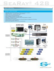
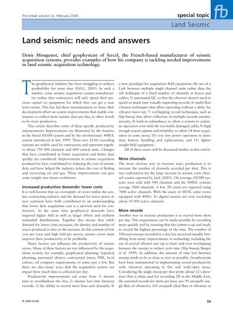
first break volume 22, February 2004<br />
special topic<br />
<strong>Land</strong> Seismic<br />
<strong>Land</strong> <strong>seismic</strong>: needs and answers<br />
Denis Mougenot, chief geophysicist of <strong>Sercel</strong>, the French-based manufacturer of <strong>seismic</strong><br />
acquisition systems, provides examples of how his company is tackling needed improvements<br />
in land <strong>seismic</strong> acquisition technology.<br />
The geophysical industry has been struggling to achieve<br />
profitability for some time (IAGC, 2003). In such a<br />
market, some <strong>seismic</strong> acquisition system manufacturers<br />
realize that contractors will only spend their precious<br />
capital on equipment for which they can get a near<br />
term return. This has led these manufacturers to focus their<br />
development effort on system improvements that enable contractors<br />
to collect more <strong>seismic</strong> data per day, in other words<br />
to be more productive.<br />
This article describes some of these specific productivity<br />
enhancements. Improvements are illustrated by the features<br />
in the <strong>Sercel</strong> SN388 system and by the revolutionary 408UL<br />
system introduced in late 1999. These two 24-bit recording<br />
systems are widely used by contractors and represent together<br />
about 750 000 channels and 600 central units. Changes<br />
that have contributed to faster acquisition and better data<br />
quality are considered. Improvements in <strong>seismic</strong> acquisition<br />
productivity have contributed to reducing the cost of <strong>seismic</strong><br />
data and have helped the industry reduce the cost of finding<br />
and recovering oil and gas. These improvements can give<br />
some insight into future evolutions.<br />
Increased production demands/ lower costs<br />
It is well known that an oversupply of crews within the <strong>seismic</strong><br />
contracting industry and the demand for lower prices in<br />
new contracts have both contributed to an understanding<br />
that lower data acquisition cost is a survival need for contractors.<br />
At the same time geophysical demands have<br />
required higher fold as well as larger offsets and uniform<br />
azimuthal distributions. Together this means that while<br />
demand for lower costs increases, the density and number of<br />
traces produced is also on the increase. In this context of low<br />
cost per trace and high fold per survey, <strong>seismic</strong> crews must<br />
improve their productivity to be profitable.<br />
Many factors can influence the productivity of <strong>seismic</strong><br />
crews. Many of these factors are not influenced by the acquisition<br />
system, for example, geophysical planning, logistical<br />
planning, personnel choices, contractual issues, HSE, local<br />
culture, oil company requirements, to name just a few. But<br />
there are also many ways that the acquisition system can<br />
impact how much data is collected per day.<br />
Productivity improvements can come from 1) shorter<br />
time to troubleshoot the line; 2) shorter lost time between<br />
records; 3) the ability to record more lines and channels; 4)<br />
a new paradigm for acquisition field equipment, the use of a<br />
Link between multiple single channel units rather than the<br />
old technique of a fixed number of channels in boxes and<br />
cables; 5) automated QC so that the observer doesn’t need to<br />
spend so much time visually inspecting records; 6) multi-fleet<br />
vibrator techniques that allow operating without a delay for<br />
vibrator move-up; 7) overlapping record techniques, such as<br />
Slip-Sweep that allow collection of multiple records simultaneously;<br />
8) built-in redundancy to allow a system to continue<br />
operation even with the inevitable damaged cable; 9) high<br />
enough system uptime and reliability to allow 24-hour acquisition<br />
in some areas; 10) very low power operation to minimize<br />
battery handling and replacement; and 11) lighter<br />
weight field equipment..<br />
All of these issues will be discussed further in this article.<br />
More channels<br />
The most obvious way to increase trace production is to<br />
increase the number of channels recorded per shot. This is<br />
one explanation for the large increase in <strong>seismic</strong> crew channel<br />
counts reported by Jack (2003). On average, SN388 systems<br />
were sold with 940 channels and the 408UL systems<br />
average 1860 channels. A few 3D crews are reported using<br />
7000 active channels. With the onset of 3D/3C some crews<br />
equipped with 4000+ 3C digital sensors are even recording<br />
about 10 000 active channels.<br />
More records<br />
Another way to increase production is to record more shots<br />
per day. This requirement can be made possible by recording<br />
more quickly and by ensuring that the system is up and ready<br />
to record the highest percentage of the time. The number of<br />
Vibroseis sweeps recorded in a day has increased steadily benefiting<br />
from many improvements in technology including the<br />
use of several vibrator sets (up to four) and even overlapping<br />
between the sweeps to reduce cycle time (Slip-Sweep; Burger<br />
et al. 1999). In addition, the amount of time lost between<br />
sweeps needs to be as close to zero as possible. Geophysicists<br />
have been instrumental in implementing record productivity<br />
with vibrators operating in flat and wide-open areas.<br />
Considering the single sweep per shot point (about 12 s duration)<br />
that is often used for recording 3D in the Middle East,<br />
the reported records for shots per hour are: 95 sweeps/h (single<br />
fleet of vibrators); 145 sweeps/h (dual fleet of vibrators in<br />
© 2004 EAGE 59
special topic<br />
<strong>Land</strong> Seismic<br />
first break volume 22, February 2004<br />
alternate flip-flop mode); 215 sweeps/h (four fleets of vibrators<br />
in overlapping Slip-Sweep mode). Thus, using multiple<br />
fleets of vibrators makes it possible to record data close to<br />
continuously, and to increase shot point density.<br />
Source-driven recording<br />
To implement fleet management, vibrator electronics must be<br />
carefully integrated within the central unit to get the recording<br />
started by the vibrators as soon as one fleet has reached<br />
the next shot point. In this source driven operation mode, the<br />
recorder must not delay the source. With the introduction of<br />
a very large spread (> 4000 channels), line forming (i.e. the<br />
selection of the active channels to be recorded by one set of<br />
vibrator) has been the main cause of dead time (up to 6 s<br />
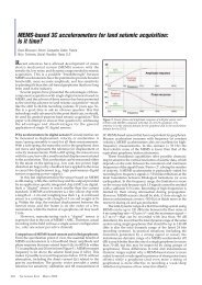
between records with SN388). With the concept of superspread<br />
implemented in the 408UL, all the channels available<br />
into a large template are recorded (Figure 1). Using the SPS<br />
relation file, the workstation will then select the active channels<br />
of the spread for data processing, formatting and storage<br />
on the cartridge. A 15% improvement of productivity in<br />
flip-flop mode has been reported due to this software implementation.<br />
New concept ground equipment<br />
For generations of <strong>seismic</strong> recording systems, the equipment<br />
consisted of recording boxes, cables, geophones and batteries.<br />
The same configuration was used for truck-based operations<br />
as in the desert, helicopter operations and manportable<br />
operations. It was simply a case of the crew adapting<br />
to the equipment the best they could. With the introduction<br />
of a new concept in ground equipment called a Link, the<br />
408UL offered equipment that could adapt to the operation,<br />
helping to increase the efficiency of a specific crew on a specific<br />
job. The Link is a single handleable unit including cable<br />
and a user defined number of single station recording electronics<br />
units which can be designed for the operation including<br />
the distance between stations and the number of stations<br />
per handling unit. In this way the most efficient amounts of<br />
equipment for the particular logistical environment can be<br />
moved as one unit.<br />
The weight of the equipment deployed in the field can<br />
cause logistical and safety problems. It can slow productivity<br />
and is one of the main sources of operational costs. Some<br />
high channel count, high productive crews in the Middle East<br />
with large geophone arrays may have to handle about 35<br />
tons of equipment daily. With the rising number of channels,<br />
lighter field equipment becomes mandatory. One 408UL<br />
channel, including cable, field electronics and battery, is 3 Kg<br />
for 55 m cable length. This is a reduction of 50% with<br />
respect to the previous SN388 system. This improvement is<br />
related to more integrated electronics with fewer components<br />
which are lighter, more reliable and require less power.<br />
From the SN388 to the 408UL, the per channel power consumption<br />
has decreased from 240 mW to 140 mW. Lower<br />
power needs translate into fewer batteries and less weight, as<br />
well as higher reliability and longer electronics life.<br />
Improved reliability of the system once it is laid out is<br />
another factor that contributes to decreased downtime/cost.<br />
Figure 1 408UL super-spread in flip-flop operations prevents dead time due to line forming. All channels of the super-spread<br />
(a large template) are transmitted at once. Then the SPS relation file is used for sorting the lines corresponding to the active<br />
spreads flip and flop. With the SN388 line, forming of spread flop after recording of spread flip introduces a delay.<br />
60<br />
© 2004 EAGE
first break volume 22, February 2004<br />
special topic<br />
<strong>Land</strong> Seismic<br />
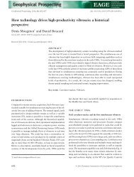
Figure 2 Multi-path telemetry thanks to multiple transverses. After a break of the receiver line, data are rerouted using another<br />
path. Recording can continue before repair of the receiver line.<br />
Another real benefit of the Link configuration is the decrease<br />
in the number of connector and contacts on the line. The<br />
Link makes it possible to decrease the number of contacts to<br />
eight (two connectors x four wires) per Link for any number<br />
of channels. For a single SN388 unit using a seven pair telemetric<br />
cable the corresponding number of contacts is 28 (two<br />
connectors x 14 wires).<br />
Increased layout flexibility/ better troubleshooting<br />
As the <strong>seismic</strong> spread grows in size and complexity, the chance<br />
of something going wrong (from chewing animals, unfriendly<br />
machetes or any number of unforeseen causes) increases dramatically.<br />
Creative ways must be found to locate and deal with<br />
these problems immediately. In the 408UL the <strong>seismic</strong> spread<br />
has been transformed into a network capable of communications<br />
as well as data routing. It is called the Seismic Areal<br />
Network. This network supports a ‘TCP/IP like’ communication<br />
protocol close to the very robust one used for the Internet.<br />
It is created by linking servers (the field electronics) together.<br />
Each server gets the packets closest to their destination (the<br />
central unit). A packet may travel over many types of media<br />
(copper cable, optic fibre, laser, microwave, radio). The<br />
Seismic Areal Network offers more flexibility and redundancy<br />
for improved productivity. During layout of the spread, multiple<br />
telemetry support (radio, laser…) may be inserted anywhere<br />
in the spread to manage detours (plant…) and obstacles<br />
(river, highway…). In case of failure between two servers (leakage…)<br />
a new transmission may be required for the data stored<br />
in the buffers. Multi-path telemetry is also possible which corresponds<br />
to the definition by the central unit of a new route to<br />
transmit data using different receiver lines and transverses to<br />
go around a break in the network (Figure 2).<br />
Better data<br />
Beyond economic considerations, data quality requirements<br />
have increased the need for greater channel production on<br />
crews around the globe. Improved spatial sampling in both the<br />
shot and the receiver domains is a prerequisite for noise attenuation.<br />
Today’s shot and receiver spacing used by most of the<br />
land 3D crews (50 m or 60 m along the corresponding shot<br />
and receiver lines) is too large to avoid ground roll aliasing.<br />
This is the reason for a trend toward decreasing the receiver<br />
spacing to 25 m. Of course, not only noise benefits from better<br />
spatial sampling but also signal (Vermeer, 2002). The<br />
increase in fold coverage and related signal-to-noise ratio is<br />
one of the improvements. If the additional channels are used<br />
to increase sampling in the cross-line direction (i.e. to layout<br />
more receiver lines) this will provide wider azimuthal distribution.<br />
Such wide distribution should improve migration operations<br />
and multiple attenuation (Cordsen and Galbraith, 2002),<br />
and it is mandatory to define anisotropy.<br />
To be able to record the large number of channels necessary<br />
to improve spatial sampling in the inline and/or crossline<br />
directions, the recording system should be able to collect, QC<br />
and record all the active lines on tape in real-time (i.e. with no<br />
dead time between shots). Downtime due to layout and maintaining<br />
the spread should be as low as possible. Multiple<br />
source management and source driven acquisition (i.e. recording<br />
as soon as one source is ready) should be available. Most<br />
of these capabilities have been implemented within SN388 and<br />
408UL as well as by the other recording systems.<br />
Real-time QC<br />
Quality control of the field instruments, data and operations is<br />
a major factor contributing to increased crew productivity. QC<br />
in the 408UL has been improved by the real time capabilities<br />
of the Seismic Areal Network for data and commands. More<br />
and more, software is used to automate acquisition (for example,<br />
relating a given spread to a given shot) and to visually display<br />
QC results. From the recording truck, the spread is<br />
checked as soon as it is laid out. The observer gets a real time<br />
numerical (table) and graphical displays highlighting faults<br />
(for example, noise above threshold, sensor tilt error, cable<br />
leakage, or low batteries). By monitoring the parameters of<br />
each sweep (phase, distortion and force) for each vibrator, it is<br />
possible to identify trends and to ask for preventive vibrator<br />
maintenance. Geographical Information System (GIS) photos<br />
are used with the control displays to put QC data in their environmental<br />
context. Operator vehicles are not only tracked for<br />
safety, but also to optimize their movement on the spread. In<br />
© 2004 EAGE 61
special topic<br />
<strong>Land</strong> Seismic<br />
first break volume 22, February 2004<br />
the recording truck, the fold coverage is built up on each shot.<br />
If the decision to record a particular shot point is in question,<br />
the effect on the final fold coverage may be simulated to understand<br />
the impact of the decision.<br />
For <strong>seismic</strong> data, real time automated QC has been also<br />
implemented. A dedicated workstation is connected by<br />
Ethernet to the central unit, in parallel with the SCSI tape<br />
drive. Since visual inspection of the increasing number of<br />
traces is impossible, quality is evaluated by means of <strong>seismic</strong><br />
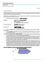
attributes computed trace-by trace in real time. In the SQC-<br />
Pro software, a history panel displays attributes averaged on a<br />
Figure 3 History view in <strong>seismic</strong> real time QC (SQC-Pro).<br />
Synthetic instrument and <strong>seismic</strong> data QC are displayed with<br />
respect to the successive shot points (SP). The observer is<br />
able to identify trends and anticipate troubles.<br />
shot-by-shot basis (Figure 3). In addition to the faulty trace<br />
count evolution, the many reasons for which a trace may be in<br />
error are also on display, such as anomalous values of the geophone<br />
tilt, resistance or leakage, signal-to-noise or bandwidth<br />
below a predefined threshold. The source noise and the signal<br />
level, isolated by FK filtering, are also provided as a quick<br />
diagnostic. All these <strong>seismic</strong> QC results are not only useful for<br />
the observer. They are stored as ADS files (SEG format for<br />
attributes) for possible later use in processing.<br />
Today, a recording truck is like a decision room, often with<br />
five or more large screens displaying data. With all this information,<br />
the observer should be able to anticipate situations<br />
and to be responsive for faster troubleshooting. However, two<br />
eyes may not be enough to take care of all QC situations.<br />
Addition of a specific QC observer is one solution. The extension<br />
of the acquisition network to a remote location, where<br />
more expertise is available, is another possibility. By adding a<br />
web server into a recording truck equipped with satellite data<br />
transmission, it is now possible to connect to the central unit<br />
any standard PC platform loaded with the eSQC-Pro software.<br />
With this remote access to <strong>seismic</strong> data (QC attributes and<br />
traces after lossy compression), any authorized person will be<br />
able to check the acquisition data quality with no delay, on the<br />
same system as the observer.<br />
Full digital transmission<br />
It took 30 years from the development of the first digital<br />
recorders to be able to move the analogue-to-digital converter<br />
from the central unit to the sensor (Figure 4). With the<br />
advent of digital sensor technology based on the MEMS<br />
accelerometer, full digital transmission becomes a reality.<br />
Suppression of the last segment for analogue transmission,<br />
the cable connecting the geophones to the station electronics,<br />
should remove all pick-up noise, cross-talk and sensitivity to<br />
leakage.<br />
Figure 4 Towards the full digital transmission or 30 years of digital recorders.<br />
(A/D refers to analogue-to-digital converter; SU1 to station unit 1 channel; DSU to digital sensor unit; and CCU/CMXL to<br />
central units).<br />
62<br />
© 2004 EAGE
first break volume 22, February 2004<br />
special topic<br />
<strong>Land</strong> Seismic<br />
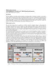
These MEMS accelerometers have been developed for the<br />
<strong>seismic</strong> industry by Input-Output (J. Tessman et al. 2002) and<br />
<strong>Sercel</strong> (M. Farine et al. 2003). In addition to a flat and broadband<br />
linear response in phase and amplitude, these new sensors<br />
combine low distortion (less than 90 dB) with the high<br />
dynamic range (above 110 dB) necessary to record quality <strong>seismic</strong><br />
data. These digital sensors, being used as single sensors,<br />
provide the full benefit of point receiver recording: no high frequency<br />
attenuation and isotropic azimuthal recording.<br />
However, single sensors present some drawbacks: no random<br />
or organized noise attenuation, short spacing (i.e. more channels)<br />
to increase fold and avoid ground roll aliasing. For threecomponent<br />
recording, 3C digital sensors have a proven record<br />
of superior vector fidelity and better data, compared with<br />
strings of geophones (R.R Kendall et al. 2002).<br />
What’s next?<br />
The <strong>seismic</strong> technique is a general tool that has grown in its’<br />
application as needs have dictated and technology has<br />
allowed. Energy reserves have generally become more difficult<br />
to define and generally hide in more difficult environments. As<br />
this technique has grown to fit the needs presented in the past,<br />
we very much feel it will continue in the same way. Fully<br />
exploiting existing reserves as well as locating new reserves<br />
will require data that penetrates geological conditions such as<br />
gas clouds, defines fracture production in tight sands, and<br />
locates subtle traps or residual and bypassed reserves.<br />
Describing reservoirs will ultimately provide energy where it<br />
had previously been overlooked. All of this will require better<br />
sampling, more channels and higher quality data.<br />
Before a survey can be recorded it must be located and laid<br />
out on the ground. Front-end costs for surveys have grown<br />
right along with survey size and complexity. GPS systems and<br />
support equipment must develop to allow stakeless surveying,<br />
thereby reducing preparation time before the <strong>seismic</strong> survey<br />
starts while ensuring that the survey is located properly.<br />
One trend is apparent. System channel counts will continue<br />
to rise. For better imaging of deep targets, fold and offset<br />
should increase. Wide azimuth 3D acquisition that improves<br />
imaging and anisotropy detection requires the recording of a<br />
swath with comparable inline and crossline offsets. Multicomponent<br />
acquisition for full elastic parameters definition<br />
and single sensor recording for more accurate wave-field sampling<br />
will require the recording of more and more channels. As<br />
an example, a 3D survey that corresponds to a square swath<br />
of 8 x 8 km 2 , with 25 m between single 1C sensors inline and<br />
crossline, would need 103 000 active channels and about 50<br />
000 more for roll-on/roll-off. This figure would be multiplied<br />
by three for 3C, and it is at least one order of magnitude above<br />
the real time capabilities of today’s recording systems.<br />
The recording system of tomorrow will face a huge list of<br />
improved technologies:<br />
■ Higher telemetry rates - no matter what the medium<br />
■<br />
■<br />
■<br />
■<br />
■<br />
■<br />
Recording hardware technology with the capability to keep<br />
up with increased data rates<br />
Recording media technology which allows huge storage<br />
and small volume<br />
Lower power consumption<br />
Improved power sources<br />
Smaller, much smaller, higher reliability electronics technology<br />
Automated QC to keep up with the increased volumes of<br />
data<br />
All of these are important issues but power management and<br />
telemetry bandwidth are two of the most difficult. Software<br />
and computer power will continue to replace hardware applications<br />
whenever possible as higher computer power in smaller<br />
packages become available.<br />
The geophysical industry is a dynamic, technology-driven<br />
industry that continues to challenge our creativity and determination.<br />
Our future will continue to present adapt-or-die<br />
challenges, as it did in the past. In many ways our industry is<br />
not any different from many others, such as telecommunications<br />
or aerospace, we just get to work in places that others<br />
can only dream about.<br />
Acknowledgements<br />
The author gratefully acknowledges all the <strong>Sercel</strong> R&D team<br />
for information provided about the SN388 and 408UL recording<br />
systems. Stimulating discussions with Jacques Hamon,<br />
Jean-Paul Ménard and Gilles Chiffoleau were instrumental in<br />
understanding some trends in acquisition systems. Final review<br />
by Bob Albers and George Wood was very helpful.<br />
Selected references<br />
Burger P., Duijndam B., and Wasmuth D. [1999] Marine production<br />
levels in land 3D <strong>seismic</strong>. The Leading Edge 10, 1170-<br />
1175.<br />
Cordsen A. and M. Galbraith M. [2002] Narrow –versus wideazimuth<br />
land 3D <strong>seismic</strong> surveys, The Leading Edge 8, 764-770.<br />
Farine M., Thorburn N. and Mougenot D. [2003] General<br />
Application of MEMS Sensors for <strong>Land</strong> Seismic Acquisition –<br />
Is it Time? CSEG Calgary.<br />
IAGC, [2003] Industry at a crossroads: A message from the<br />
geophysical industry, The Leading Edge, 14-17.<br />
Jack I. [2003] <strong>Land</strong> <strong>seismic</strong> technology: Where do we go from<br />
here? First Break 21, 41-44.<br />
Kendall R.R., Maxwell P., Cheadle S., Burnett R. and Watt H.<br />
[2002] VectorSeis – Initial Results from a New<br />
Multicomponent Sensor, CSEG Calgary..<br />
Tessman J., Reichert B., Marsh J., Gannon J. and Goldberg H.<br />
[2002] MEMS for Geophysicists, EAGE 64th Conference &<br />
Exhibition A-10.<br />
Vermeer G.J.O. [2002] 3D Seismic Survey Design. SEG<br />
Geophysical reference series 12, SEG.<br />
© 2004 EAGE 63