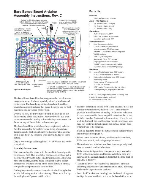
Bare Bones Board Arduino Assembly Instructions, Rev ... - Wulfden.org
Bare Bones Board Arduino Assembly Instructions, Rev ... - Wulfden.org
Bare Bones Board Arduino Assembly Instructions, Rev ... - Wulfden.org

Create successful ePaper yourself
Turn your PDF publications into a flip-book with our unique Google optimized e-Paper software.
<strong>Bare</strong> <strong>Bones</strong> <strong>Board</strong> <strong>Arduino</strong><br />
<strong>Assembly</strong> <strong>Instructions</strong>, <strong>Rev</strong>. C<br />
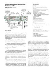
Outline for TO-92 voltage regulator<br />
listed. (250mA). For more current, use<br />
a TO-220 regulator but be sure and<br />
reverse the insertion direction.<br />
Use right-angle header<br />
pins here, if you want<br />
cable to stick out<br />
sideways, instead of up.<br />
observe notch on<br />
28 pin DIP socket<br />
and Atmega168 chip<br />
figure 1: BBB layout<br />
The <strong>Bare</strong>-<strong>Bones</strong> <strong>Board</strong> has been engineered to be a low-cost<br />
easy-to-construct <strong>Arduino</strong>, specially aimed at students and<br />
prototypers. The board plugs into a breadboard, and has<br />
several convenient features that make it easy to use for both<br />
beginning and advanced prototyping.<br />
Despite its title, the <strong>Bare</strong>-<strong>Bones</strong> <strong>Board</strong> includes all of the<br />
functionality of the most robust <strong>Arduino</strong> boards, and even<br />
some recommended analog noise-reducing components not<br />
found on any of the <strong>Arduino</strong> reference designs.<br />
The boards and kits, which have been engineered to be as<br />
flexible as possible for widely varied types of prototype<br />
designs, can be built in an hour by a beginner at soldering,<br />
or in a half-hour by someone who has built a few of them<br />
before.<br />
Only a low-wattage soldering iron (15 - 25 Watts), and solder<br />
is required.<br />
<strong>Assembly</strong> <strong>Instructions</strong><br />
TO-92<br />
resonator<br />
surface-mount<br />
inductor<br />
TO-220<br />
Shorting clip (on header<br />
pins) for selection of USB<br />
or External power here.<br />
Shorting clip (on header<br />
pins) for selection of<br />
voltage regulator (5V) or<br />
External power here.<br />
(see text)<br />
These header pins on bottom of board for convenient<br />
breadboard use. All others mounted on top.<br />
For "shield" boards feel free to mount these pins on<br />
top of the board. Use female connectors if desired.<br />
Also double-headed male connectors are available,<br />
(Digikey S1031E-31-ND.)<br />
Start assembling the board with the smallest, lowest profile<br />
components first. That way taller components will not get in<br />
the way when trying to install smaller components. Also when<br />
parts are inserted, and the board is flipped over to solder,<br />
components will tend to stay in the board better, if similar,<br />
low-profile components are inserted first.<br />
For beginners that have never done electrical soldering before<br />
see the Soldering section before starting. There are a few tips<br />
for multiple-unit "power builders" too.<br />
Parts List<br />
Inductor<br />
1 15 uH surface-mount inductor<br />
Axial 1/4W Resistors<br />
2 10k (brown - black - orange)<br />
1 1M (brown - black - green)<br />
1 1k (brown - black - red)<br />
Capacitors<br />
4 .1ufd (104) ceramic, 25 V<br />
2 4.7-47 ufd tantalum or electrolytic<br />
capacitors (polarized), 25V<br />
Semiconductors<br />
2 400x 1amp power diodes<br />
1 L4931CZ50LDO 5V, low-dropout<br />
voltage regulator, TO-92 package<br />
optional - LM2937 500 mA LDO regulator<br />
TO-220 package<br />
1 3mm (T1) LED any color<br />
1 Atmega168 28 pin DIP package<br />
preprogrammed with bootloader<br />
1 16 MHZ ceramic resonator with built-in<br />
capacitors, three-terminal SIP package<br />
Hardware<br />
50 snap-off male header pins .100" centers,<br />
or .100" femail headers as desired.<br />
6 right-angle male-header pins .100" centers<br />
1 momentary switch<br />
1 28 pin (narrow .3") IC socket OR<br />
2, 14 pin DIP sockets<br />
2 .100" header 2 position shorting clip (shunt)<br />
1 1.3mm power jack, Digikey CP-2519-ND<br />
FTDI TTL-232R programming cable FTDIchip.com<br />
5 Volt - 1A power adapter (optional)<br />
All Electronics CAT# PS-504<br />
• The first component to deal with is the smallest, the 15 uH<br />
surface-mount inductor, marked "150". This inductor<br />
provides a small amount of analog (A/D) noise reduction,<br />
it is recommended in the Atmega168 datasheet, but is not<br />
included in other <strong>Arduino</strong> implementations. If you do not<br />
wish to deal with the small surface mount component you<br />
may just solder up (short circuit) the surface mount pads<br />
where it was to be mounted.<br />
If you do decide to mount the surface-mount inductor follow<br />
the instructions on page_4.<br />
• Solder in the resistors, diodes, small ceramic capacitors,<br />
LED, reset switch, and voltage regulator next.<br />
• The resistors and smaller capacitors have no polarity and<br />
may be inserted in either direction.<br />
• Make certain that polarized components, such as diodes,<br />
LED, voltage regulator, and larger electrolytic caps are<br />
inserted in the correct direction. Note that the long lead on<br />
the LED is positive.<br />
• Mount the two 47 uF electrolytic capacitors, carefully<br />
observing the polarities and orientation of each. The long<br />
leads on the capacitors are positive.<br />
• Insert the IC socket (not the chip) into the board, taking care<br />
to align the notch with the notch on the board silkscreen.
For larger and multi-pin components, such as the chip socket<br />
and header pins, there is a little trick that may be helpful<br />
to get them mounted neatly.<br />
Solder in one pin only, or in the case of the socket, two<br />
diagonal corner pins. Then flip the board over to inspect it.<br />
If the component is not mounted tightly down on the board,<br />
simply put a little pressure on the component with your<br />
index finger while reheating the soldered pad(s) with the<br />
soldering iron, this will get the part mounted down flush<br />
before you solder in the other pins.<br />
• Solder in the power jack.<br />
• Solder in the header pins. The board is made to be easy to<br />
customize for particular applications. The following<br />
instructions are for the most standard orientation for header<br />
pins, but feel free to mount (or omit them) as you wish. In<br />
some installations it may be more robust and reliable to<br />
solder wires directly to the board.<br />
• The seventeen digital output header pins gets inserted into<br />
the bottom of the board and soldered on the top, as do the<br />
two pins, at front right, that are designed to power the<br />
breadboard. Mount these pins last after the others are mounted<br />
on top.<br />
• All other header pins get inserted into the top of the board<br />
and soldered on the bottom. Using right-angle header pins<br />
for the USB-to-Serial cable connector makes the cable<br />
convenient to connect.<br />
• Finally, mount the resonator (marked XTAL on board). It<br />
can be inserted either way but it's a good idea to insert it<br />
with the label showing.<br />
• Hobbyists and prototypers often omit this step, but it's a<br />
good idea to clean the solder flux off your board with a<br />
toothbrush and isopropyl (not denatured) alcohol. Scrub and<br />
rinse with clean alcohol until the board looks flux-free. Dry<br />
it off a little with a paper towel or rag and have a good<br />
inspection of your solder joints, to make sure pins are not<br />
bridged (shorted) with solder, and that all the solder joints<br />
look shiny, smooth, and cover the pads completely.<br />
Questionable solder joints may be fixed simply by reheating<br />
with the soldering iron.<br />
• Add the shorting clip to the power selection header in the<br />
desired position, and the J1/J2 shunt (see below).<br />
Testing your BB <strong>Arduino</strong><br />
• Put the USB / EXT shorting clip on the power selector pins.<br />
Power up the board, either with the programming cable or<br />
an external supply and make sure that the pilot light goes<br />
on. If not, disconnect the power right away, and consult the<br />
troubleshooting section. Do a check with a multimeter for<br />
5 volts at the power pins to the left end of the digital<br />
breadboard pins.<br />
• If all seems well, disconnect the power, and insert your<br />
Atmega 168 chip into the socket, taking care to align the<br />
notch on the chip with the notch on the socket and on the<br />
board silkscreen. Chips come from the factory with the legs<br />
splayed, and the chip will be much less fuss to insert if you<br />
2<br />
perform the following operation. Hold the chip exactly<br />
perpendicular to a table and press down until the all the legs<br />
have a 90 degree angle to the chip top. Flip, repeat, and<br />
you're ready to put the chip into the socket.<br />
• Next hook up a LED and a 1K series resistor on pin 13.<br />
Boot up the <strong>Arduino</strong> application and try downloading the<br />
blinking light program. Push the reset button on the board<br />
and click the download icon at about the same time.<br />
• If your board doesn't seem to work, see the troubleshooting<br />
guide on page 6.<br />
Powering the BBB <strong>Arduino</strong>.<br />
There are two options for powering the <strong>Arduino</strong> <strong>Board</strong>.<br />
The USB cable can supply 5 volts to the board. How much<br />
current the FTDI 232R cable can provide is an open question.<br />
The USB standard calls for available current to be controlled<br />
by software and the cable's manufacturer quotes 50 mA as<br />
the amount of available current. (This limit is from the<br />
expected behavior of the USB interface and not any electrical<br />
limit from the cable.)<br />
In practice, a Mac and a PC I tested were both able to<br />
provide 500 mA, which is as high as I went in my testing.<br />
Since I can't get access to any of the software interaction, it<br />
is impossible for me to know if the cable's software "asks"<br />
for higher current limits or the USB ports just generously<br />
provides more without being asked. I would guess the latter.<br />
USB is a convenient option for powering your board<br />
because it eliminates other wires and batteries and it should<br />
be viable for many projects that only involve interfacing<br />
sensors, lighting LED's, or communicating with a<br />
laptop/desktop computer.<br />
For circuit experiments and construction you are probably<br />
better off using a 5 - 9 volt power adapter. This will take the<br />
strain off your laptop battery and protect more expensive<br />
systems in the case of short circuits and the like. For powering<br />
small DC motors or solenoids especially, you will be much<br />
better off using an external power supply.<br />
The board contains a 5 volt low-dropout regulator. In the<br />
case of an accidental short circuit, the voltage regulator on<br />
the board will limit the current draw to about 300 mA. This<br />
should protect the power supply although the regulator will<br />
get very hot. The tipoff to a short circuit will be the LED<br />
pilot light going off, and of course, a hot regulator, if you put<br />
your finger on it.<br />
J1 / J2 Shunt or jumper<br />
J1 or J2 is an option that sets how the BB <strong>Arduino</strong> is<br />
connected to the two breadboard bus power pins on the right<br />
side of the board.<br />
Use J1 in these cases:<br />
J1 jumper is used to power for the breadboard powerrail<br />
bus comes through the <strong>Arduino</strong> LDO voltage regulator.<br />
Use this if you want to power your breadboard from your<br />
<strong>Arduino</strong> adapter, and the adapter is between 5-9 volts. Most<br />
users will probably want this option, unless you have DC<br />
motors running on the breadboard.
3<br />
Use J2 in these cases:<br />
jumpered<br />
voltage regulator<br />
<strong>Bare</strong>-<strong>Bones</strong> <strong>Arduino</strong> module with header pins set up for breadboard use. There are<br />
several options for the header pins depending on the project requirements.<br />
J2 is used to connect power to (or from) the breadboard<br />
power-rail bus, directly from the <strong>Arduino</strong> power jack. In most<br />
cases you probably don't want a higher voltage than 5 volts on<br />
the breadboard power rail so use this option only with a regulated<br />
5 V adapter such as the All Electronics unit in the parts list.<br />
J2 can also be used if you have a powered breadboard, with<br />
regulated 5 volts available, and you want to run your BB <strong>Arduino</strong><br />
from the breadboard rails. It is also possible to use J1 when<br />
powering the BBB off 5V breadboard rails - in that case, the<br />
regulator would not be in the circuit.<br />
Options, Parts You Perhaps Don't Need<br />
The <strong>Bare</strong>-<strong>Bones</strong> <strong>Arduino</strong> was engineered to<br />
be a small, versatile prototyping board, so<br />
depending on your circumstances, there may<br />
be several parts you can do without.<br />
If your BB <strong>Arduino</strong> is tethered to a laptop or desktop computer<br />
as an IO device you may just want to run off USB. In this case<br />
the low-dropout regulator is redundant and you could just solder<br />
a jumper from one outside pin to the other.<br />
If you are powering the board from a 5 volt, regulated<br />
adapter, such as the All Electronics model listed on the parts<br />
list, you could also leave out the regulator and one of the<br />
electrolytic capacitors that are associated with the regulator.<br />
The pilot light and its associated resistor is a useful feedback<br />
signal, but if you are building a battery powered device which<br />
requires minimal power draw, for example, leave out the LED<br />
and add an LED (with series resistor) connected to an <strong>Arduino</strong><br />
digital pin and blink the LED every 3 or four seconds, to save<br />
power.<br />
Any of the header pins can be left out, or soldered on the<br />
top or bottom of the board, or can be replaced by female headers,<br />
(for mating with shield boards, for example). One flexible option<br />
might be to use longer, male, header pins that protrude both<br />
above, and below, the board. This would make it possible to<br />
use your BB <strong>Arduino</strong> with either a breadboard, or a shield board.<br />
See Digikey part # S1031E-36-ND for example.<br />
You could even leave out the 16 Mhz resonator, and program<br />
the Atmega168 chip to run on the internal RC oscillator, at 8<br />
Mhz. This would require reprogramming the Atmega168 fuses.<br />
This is not rocket science, but not for those impatient with trial<br />
& error, in my experience, see<br />
http://www.arduino.cc/playground/Learning/Atmega83-3V.<br />
Please let us know if there are features you think would be<br />
handy or should be built into the next version. Corrections and<br />
suggestions for this documentation are also highly valued and<br />
appreciated. Most will be implemented immediately.<br />
A BBB pcb board shown actual size,<br />
for comparison purposes. The production run boards<br />
however, are white, not green.
Inductor<br />
schematic symbol<br />
Inductors (coils) act to oppose a change in current. In the BBB circuit<br />
the inductor's role is to reduce fast-changing power-supply noise.<br />
The 15 mh (millihenry) inductor is the only surface-mount component<br />
on the board. Here's how to mount it.<br />
soldering<br />
iron<br />
solder<br />
Place the inductor on the pad, hold it down by laying an Exacto knife<br />
or needlenose pliers on top of it, and heat the pad, (do not touch the<br />
inductor with the soldeing iron). Solder will rapidly flow onto the pad<br />
and inductor, lift the soldering iron immediately. This will hold the<br />
inductor down, touch the other pad for a second with some solder<br />
and your soldering iron, and you're almost done. Just reheat the first<br />
side quickly to insure a good solder joint.<br />
Don't worry if the inductor is not on perfectly straight, the electricity<br />
can't tell the difference. Don't overheat it either, it's small and will<br />
solder quickly. If it's really crooked, you can position it by quickly and<br />
alternately heating opposite ends and pushing gently with the soldering<br />
4<br />
Capacitors<br />
Capacitors are components that store electrical energy<br />
(charge). There are several different technologies that<br />
are used to construct capacitors. The BBB contains<br />
ceramic capacitors, that are not polarized, and electrolytic<br />
capacitors, that are polarized, and must be inserted with<br />
the correct orientation.<br />
104<br />
LED<br />
markings and<br />
color may vary<br />
,1 ufd<br />
(104)<br />
ceramic<br />
(not polarized)<br />
schematic symbol<br />
(+)<br />
negative is<br />
marked on<br />
capacitor<br />
body<br />
47 ufd<br />
electrolytic cap.<br />
(polarized)<br />
47 uf 25 V<br />
Electrolytic capacitors are<br />
marked in a slightly confusing<br />
manner. The negative side<br />
of the capacitor is marked.<br />
On circuit boards and<br />
schematics the positive side<br />
is always marked. The longer<br />
lead on the component is<br />
always positive however.<br />
positive lead<br />
is longer<br />
LED's are diodes which emit light. They are polarized like diodes so<br />
insert them in the correct direction.<br />
schematic symbol<br />
Resistors<br />
Diodes<br />
anode<br />
solder pool to short pads if not using inductor<br />
If you don't want to fuss with the tiny inductor, just leave it out and<br />
solder up the pads as shown above. No other <strong>Arduino</strong> boards include<br />
it although the Atmega 168 datasheet recommends it, and the reduction<br />
in analog noise that it provides is fairly minor.<br />
1k (1000 ohms) brown-black-red<br />
10k (10,000 Ω) brown-black-orange<br />
1M (1,000,000 Ω) brown-black-green<br />
tolerance band: gold = 5%<br />
resistors are not polarized, meaning it doesn't matter<br />
which end goes where<br />
cathode<br />
schematic symbol<br />
anode<br />
schematic symbol<br />
cathode<br />
Diodes act as electrical "one-way" valves. Electricity flows in the<br />
direction of the arrow, but not the other way. They are polarized. Stripe<br />
is negative (cathode end). Think of the stripe on the diode as the<br />
stripe in the schematic. Get the stripe oriented the correct way on the<br />
board, or the project is almost guaranteed not to work.<br />
anode<br />
Resonator<br />
cathode<br />
positive lead<br />
is longer<br />
The 16 Mhz ceramic resonator acts as a calibrated oscillator for the<br />
BBB. As you can see from the schematic, it contains a crystal element<br />
and two small capacitors. It's symmetrical, so you can't put it in<br />
backwards, but it is a good idea to put it in so that you can read the<br />
label.<br />
schematic symbol<br />
16.00M<br />
Voltage Regulator<br />
The voltage regulator is an integrated circuit which will limit higher<br />
input voltages to 5 volts. It will also limit the current flow in case of<br />
short circuits. The electronics industry calls the physical form an IC<br />
is packaged in a "package" or "case", the actual IC is always a small<br />
chip embedded somewhere in the plastic. The voltage regulator<br />
provided may vary by number but is in a TO-92 case.<br />
If you need to have more regulated power, to power a lot of high<br />
powered LED's on a breadboard, for example, then, your board will<br />
accommodate a TO-220 package regulator, such as the LM2937<br />
listed in the parts list, or the popular 7805. Just remember to insert<br />
it backwards as shown in figure 1.<br />
Make sure you get the TO-92 regulator inserted in the correct<br />
orientation. It is not symmetrical so match the part outline on the<br />
board with the regulator shape.<br />
TO-92<br />
TO-220<br />
typical 3 terminal regulator schematic symbol<br />
Prepare all the resistors and diodes for inserting into<br />
pcb by bending their leads at right angles, adjacent to<br />
the component body.<br />
5 - 9 volts In L4931CZ50<br />
5 volts out<br />
see particular device<br />
datasheets for sizes of<br />
capacitors
5<br />
USB EXT<br />
AR<br />
A5<br />
A4<br />
A3 BARE-BONES<br />
BOARD <strong>Rev</strong>. C<br />
A2<br />
A1<br />
A0<br />
G<br />
+5V<br />
0 RX<br />
1 TX<br />
2<br />
3 PWM<br />
4<br />
5 PWM<br />
6 PWM<br />
7<br />
G<br />
8<br />
9 PWM<br />
10 PWM<br />
11 PWM<br />
12<br />
13<br />
G<br />
G<br />
+5V<br />
+5V<br />
TX<br />
RX<br />
FTDI TTL-232R cable<br />
<strong>Bare</strong>-<strong>Bones</strong> <strong>Board</strong><br />
Programming cable connections between a BBB and a FTDI TTL-232R<br />
USB to TTL serial cable.<br />
Please note that the TX and RX labels refer to the cable's labeling, not the<br />
chip's. The TX label at the programming connector is electrically connected<br />
to the <strong>Arduino</strong>'s RX pin (0) and the cable's RX pin is connected to the<br />
<strong>Arduino</strong>'s TX pin.<br />
GND<br />
+5V<br />
SIGNAL<br />
An <strong>Arduino</strong> <strong>Board</strong> set up on a solderdless breadboard<br />
with six LED's ready for dimming with the PWM outputs.<br />
Hot glue over solder<br />
joints, for robust sensors,<br />
six places<br />
+5V<br />
GND<br />
SIG<br />
Radio Shack<br />
Shielded Audio Cable<br />
Signal to A0 to A5<br />
analog inputs<br />
OR<br />
Resistor to match<br />
photoresistor under<br />
"middle" illumination level<br />
Hookups for sensors. Resistive sensors<br />
are shown but <strong>Arduino</strong> analog inputs can<br />
Shield be used with any sensor designed for a<br />
Note: Wires not voltage output.<br />
in same order as<br />
other end<br />
Digikey #S7001-ND<br />
3 position .1" female<br />
connector.<br />
FTDI TTL-232R<br />
cable port<br />
breadboard<br />
power-rail<br />
bus pins<br />
GND<br />
+5V<br />
Power Select<br />
USB EXT<br />
GND<br />
CTS#<br />
VCC<br />
TXD<br />
RXD<br />
RTS#<br />
J2<br />
J1<br />
47<br />
ufd<br />
+5 -12V<br />
.1<br />
ufd<br />
GND<br />
Power Jack<br />
1.3mm<br />
center positive<br />
LDO<br />
V.R.<br />
LED<br />
<strong>Bare</strong>-<strong>Bones</strong> <strong>Board</strong> Schematic<br />
Released under Creative Commons ShareAlike License 3.0<br />
http://creativecommons.<strong>org</strong>/licenses/by-sa/3.0/<br />
10k<br />
GND<br />
47<br />
ufd<br />
.1<br />
ufd<br />
LED<br />
RESET<br />
16 Mhz<br />
resonator<br />
15<br />
uH<br />
1k<br />
9<br />
1M<br />
10<br />
AVCC<br />
20<br />
VCC<br />
7<br />
10k .1ufd<br />
GND<br />
8<br />
22<br />
ICSP header<br />
1<br />
3<br />
5<br />
ATMEGA8 or ATMEGA168<br />
19<br />
18<br />
17<br />
16<br />
15<br />
14<br />
13<br />
12<br />
11<br />
6<br />
5<br />
4<br />
3<br />
2<br />
1<br />
<strong>Bare</strong>-<strong>Bones</strong> <strong>Board</strong> <strong>Arduino</strong> Schematic<br />
2<br />
4<br />
6<br />
+5 V<br />
28<br />
27<br />
26<br />
25<br />
24<br />
23<br />
21<br />
reset<br />
ANALOG INS DIGITAL IN/OUT<br />
.1ufd<br />
D13<br />
D12<br />
D11<br />
D10<br />
D9<br />
D8<br />
D7<br />
D6<br />
D5<br />
D4<br />
D3<br />
D2<br />
D1<br />
D0<br />
A5<br />
A4<br />
A3<br />
A2<br />
A1<br />
A0<br />
AREF<br />
<strong>Arduino</strong> Pins<br />
digital pins<br />
digital pin 0 (RX)<br />
digital pin 1 (TX)<br />
digital pin 2 (INT0)<br />
d.p. 3 (INT1, PWM)<br />
digital pin 4<br />
digital pin 5 (PWM)<br />
digital pin 6 (PWM)<br />
digital pin 7<br />
digital pin 8<br />
<strong>Arduino</strong> Pins<br />
analog inputs<br />
(PCINT14/RESET) PC6 1 28 C5 (ADC5/SCL/PCINT13) analog input 5<br />
(PCINT16/RXD) PD0 2 27 PC4 (ADC4/SDA/PCINT12) analog input 4<br />
(PCINT17/TXD) PD1 3 26 PC3 (ADC3/PCINT11) analog input 3<br />
(PCINT18/INT0) PD2 4 25 PC2 (ADC2/PCINT10) analog input 2<br />
(PCINT19/OC2B/INT1) PD3 5 24 PC1 (ADC1/PCINT9) analog input 1<br />
analog input 0<br />
(PCINT20/XCK/T0) PD4 6 23 PC0 (ADC0/PCINT8)<br />
VCC 7 22 GND<br />
GND 8 21 AREF<br />
(PCINT6/XTAL1/TOSC1) 9 20 PB6 AVCC<br />
(PCINT7/XTAL2/TOSC2) PB7 10 19 PB5 (SCK/PCINT5)<br />
Atmega 168<br />
(PCINT21/OC0B/T1) PD5 11 18 PB4 (MISO/PCINT4)<br />
(PCINT22/OC0A/AIN0) PD6 12 17 PB3 (MOSI/OC2A/PCINT3)<br />
(PCINT23/AIN1) PD7 13 16 PB2 (SS/OC1B/PCINT2)<br />
(PCINT0/CLKO/ICP1) PB0 14 15 PB1 (OC1A/PCINT1)<br />
digital pin 13 (LED)<br />
digital pin 12<br />
digital pin 11 (PWM)<br />
digital pin 10 (PWM)<br />
digital pin 9 (PWM)<br />
Pin mapping of the Atmega168 chip to the <strong>Arduino</strong> <strong>Board</strong>
Troubleshooting<br />
Symptom: No pilot light.<br />
Causes:<br />
LED in backwards<br />
electrolytic capacitor in backwards<br />
voltage regulator in backwards<br />
no power select shunt (shorting clip)<br />
no power at external jack - check power adapter & polarity<br />
bad solder connection - check power at power jack &<br />
power-select pins<br />
diode in backwards (disconnect power supply right away)<br />
power supply connections reversed - check external supply<br />
with a multimeter<br />
6<br />
<strong>Arduino</strong> is an open-source hardware and software initiative<br />
closely related to the Wiring and Processing open-source<br />
initiatives.<br />
<strong>Arduino</strong> Home - http://arduino.cc<br />
Wiring Home - http://wiring.<strong>org</strong>.co/<br />
Processing Home - http://processing.<strong>org</strong>/<br />
The <strong>Bare</strong>-<strong>Bones</strong> <strong>Board</strong> is an open-source hardware project<br />
of Paul Badger and Modern Device Company<br />
moderndevice.com<br />
distributed under Creative Commons ShareAlike License 3.0<br />
http://creativecommons.<strong>org</strong>/licenses/by-sa/3.0/<br />
Procedure: check for 5 volts at power buses: at USB port, at<br />
power jack, near analog pins, at pins 7&8 of the Atmega168<br />
If 5V is found at power bus pins, LED is in backwards or<br />
poor solder joint. If low or incorrect voltage, check diodes,<br />
voltage regulator, solder joints, power supply<br />
Symptom: Pilot light on but program won't download to<br />
board<br />
Hardware Causes:<br />
Atmega168 in backwards or not seated properly (check for<br />
pins that have "escaped the socket"<br />
Atmega168 not programmed with bootloader<br />
bad cable<br />
drivers not installed on PC - Check <strong>Arduino</strong>->Tools->Serial<br />
Port<br />
solder joint at cable connector or pins 2& 3 (check for shorts<br />
or bad (solder joints) on all pins, reheat all solder joints<br />
wrong resonator value<br />
wrong resistor across resonator (1M)<br />
Procedure: if you have an oscilloscope, check for signals<br />
across resonator pins and on RX line during download.<br />
Software/PC side causes:<br />
check for FTDI drivers installed (if using USB cable)<br />
check for proper chip (Atmega168) selected in<br />
<strong>Arduino</strong>->Tools->Microcontroller->Atmega168<br />
click RESET switch simultaneously with download attempt.<br />
General "Cure-Alls":<br />
check orientation on all polarized parts, V.R., caps, diodes,<br />
V.R., socket and chip.<br />
check values of resistors<br />
Reheat all solder pads on bottom of board, look for bridges<br />
(shorts) on chip pins<br />
clean PCB with toothbrush and isopropyl alcohol
Electrical Soldering for Beginners<br />
Use a high-quality soldering iron with the sharpest point<br />
you can find. It should be rated between 15 and 25 watts.<br />
Keep the soldering iron tinned (coated with solder) at all<br />
times. The tip should look slivery and shiny. It is important to<br />
do this as soon as a new soldering iron gets hot.<br />
Wipe your soldering iron tip off on a wet sponge, or a copper<br />
"scrubbie", to keep it clean and shiny. Do this whenever the tip<br />
stops looking shiny or has too much solder buildup on it.<br />
Use either leaded or "no-lead" solder but be aware no-lead<br />
solder is a little harder to use for beginners, and makes solder<br />
joints that are slightly less shiny than leaded solder.<br />
Work in a room with some ventilation. There is a tiny bit<br />
of lead in solder fumes but the flux fumes are more of a healthhazard<br />
than the lead. Jameco sells a nice soldering iron / carbon<br />
filter combination for under $100.<br />
Heat the pad for about a second, then apply solder to the<br />
heated pad or leads, not the soldering iron. After the solder melts<br />
and "grabs" the pad, continue heating for another second.<br />
If you haven't gotten the solder to grab after about 4 seconds<br />
let the joint cool down before trying again. Too much heat can<br />
ruin electronic components, but most beginners err on the side<br />
of too little heat ("cold" solder joints). If the solder joint looks<br />
lumpy, or if the solder doesn't completely cover the pad, the<br />
solder joint needs more heat. Just reheat it again until you see<br />
the flux around it "simmer" a bit, and the solder grabs the pad<br />
and smoothes out.<br />
lead<br />
pad<br />
cold solder joint<br />
(not enough heat)<br />
solder<br />
soldering iron<br />
good solder joint<br />
• smooth meniscus<br />
• shiny<br />
• covers pad<br />
7<br />
It is a good idea to clean the solder flux off your board<br />
with a toothbrush and isopropyl (not denatured) alcohol, when<br />
you are done with your board. Most fluxes when left on the<br />
board for extended periods of time, will corrode pcb pads and<br />
traces. Additionally, fluxes are not perfect insulators, so can<br />
affect the electrical operation of your circuit.<br />
Splash a little alcohol on the board and scrub with a<br />
toothbrush. Rinse with clean alcohol and repeat until the board<br />
looks flux-free. Dry it off a little with a paper towel or rag and<br />
have a good inspection of your solder joints, to make sure pins<br />
are not bridged (shorted) with solder, and that all the solder<br />
joints look shiny, smooth, and cover the pads completely.<br />
Questionable solder joints may be fixed simply by reheating<br />
with the soldering iron.<br />
Power Soldering for Multiple-Kit Builders: or How to put<br />
together 10 BBB kits on Saturday and still have time to meet<br />
your friends.<br />
Additional items required: Piece of foam rubber - antistatic<br />
pink foam is ideal, small alligator clips.<br />
We insert parts in groups and don't bend any leads to hold parts<br />
in. Once the board is flipped for soldering, the foam holds the<br />
components agains the board. We put the boards together in<br />
4 steps.<br />
Step 1: mount the inductor, covered on page 4. You can get it<br />
straight by quickly and alternately heating either end and gently<br />
moving it.<br />
Step 2: Insert the resistors, diodes, reset switch, LED and small<br />
(104) caps. Don't bend the leads. Cover the parts with the foam<br />
and flip the whole board, then solder it. If you are worried that<br />
a part may not be seated down against the board apply some<br />
pressure to the board while heating one pin.<br />
Step 3: Cut the leads from the last step. Insert all the remaining<br />
parts except the 17 pin header and 2 pin header. If you have<br />
alligator clips, clip the programming header and the power jack<br />
to the board with them, you could also try this on the other<br />
headers if you have a lot of clips handy - the small ones are<br />
better .<br />
Put the foam on top of the board and flip the whole mess so<br />
foam is now on bottom and board is upside down. Tack down<br />
one pin only on headers and socket. Solder in all pins on<br />
electrolytic caps, resonator and parts held in with clips. (You<br />
could also inspect them first for correct fit) Flip the board to<br />
inspect "fit" on headers and socket and adjust by heating with<br />
pressure from index finger. A thimble might be useful if you<br />
haven't burned out all the nerves in your index finger soldering,<br />
as we have. Flip and finish soldering.<br />
Step 2: Insert the 17 pin and 2 pin header on bottom. Tack,<br />
inspect, straighten if necessary and solder.