Vargus - Vardex Main Catalogue
Vargus - Vardex Main Catalogue
Vargus - Vardex Main Catalogue

You also want an ePaper? Increase the reach of your titles
YUMPU automatically turns print PDFs into web optimized ePapers that Google loves.
About Thread Milling<br />
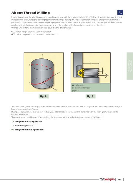
In order to perform a thread milling operation, a milling machine with three-axis control capable of helical interpolation is required. Helical<br />
interpolation is a CNC function producing tool movement along a helical path. This helical motion combines circular movement in one<br />
plane with a simultaneous linear motion in a plane perpendicular to the first. For example, the path from point A to point B (Fig. A) on the<br />
envelope of the cylinder combines a circular movement in the xy plane with a linear displacement in the z direction.<br />
On most CNC systems this function can be executed in two different ways:<br />
GO2: Helical interpolation in a clockwise direction<br />
GO3: Helical interpolation in a counter-clockwise direction<br />
<br />
Z<br />
B<br />
Y<br />
D<br />
p<br />
<br />
THread Milling<br />
Technical Data<br />
A<br />
O<br />
X<br />
: helix angle<br />
D: external diameter<br />
p: pitch<br />
Fig. A<br />
Fig. B<br />
The thread milling operation (Fig. B) consists of circular rotation of the tool around its own axis together with an orbiting motion along the<br />
bore or workpiece circumference.<br />
During one such orbit, the tool will shift vertically one pitch length. These movements combined with the insert geometry create the<br />
required thread form.<br />
There are three acceptable ways of approaching the workpiece with the tool to initiate production of the thread:<br />
u Tangential Arc Approach<br />
v Radial Approach<br />
w Tangential Line Approach<br />
245