General Delivery Specifications for Machinery and Equipment - Bosch
General Delivery Specifications for Machinery and Equipment - Bosch
General Delivery Specifications for Machinery and Equipment - Bosch

You also want an ePaper? Increase the reach of your titles
YUMPU automatically turns print PDFs into web optimized ePapers that Google loves.
<strong>General</strong> <strong>Delivery</strong><br />
<strong>Specifications</strong><br />
<strong>for</strong><br />
<strong>Machinery</strong> <strong>and</strong> <strong>Equipment</strong><br />
<strong>Machinery</strong> <strong>and</strong> <strong>Equipment</strong> (MAE) <strong>General</strong> <strong>Delivery</strong> <strong>Specifications</strong><br />
can also be found at<br />
www.boschnasuppliers.com<br />
Reference: - OP4.7.04.004<br />
Robert <strong>Bosch</strong> Corporation<br />
April, 2005
April<br />
2005 <strong>General</strong> <strong>Delivery</strong> <strong>Specifications</strong>
<strong>General</strong> <strong>Delivery</strong> <strong>Specifications</strong><br />
<strong>for</strong> <strong>Machinery</strong> <strong>and</strong> <strong>Equipment</strong><br />
Sections 1 - 9<br />
Revision 4 - April, 2005<br />
All prior editions are obsolete <strong>and</strong> should not be used.<br />
This document is controlled by:<br />
Robert <strong>Bosch</strong> Corporation<br />
ChW/BPS-LS (Industrial Engineering)<br />
8101 Dorchester Rd.<br />
Charleston, SC 29418<br />
(843) 760 - 7659<br />
wolfgang.hasper@us.bosch.com<br />
It is the user's responsibility to assure that only the latest revision of this st<strong>and</strong>ard is used.<br />
SUPANAGEMENT
BOSCH <strong>General</strong> <strong>Delivery</strong> <strong>Specifications</strong> <strong>for</strong> <strong>Machinery</strong> <strong>and</strong> <strong>Equipment</strong><br />
CHANGES MADE TO THE GENERAL DELIVERY SPECIFICATIONS SECTIONS 1-9<br />
Page Section Changes<br />
April 1, 2005<br />
2-3..5 2.2 Restructured section in order to match the Review<br />
Checklist.<br />
2-3 2.2.1 Moved Lean Manufacturing statement (BPS) to 2.2.2a.<br />
2-4 2.2.2 Added review of special attention points.<br />
4-3 4.1.2 Added awareness statement (AC has some different<br />
drawing st<strong>and</strong>ards).<br />
5-2 5.3.1 Additional in<strong>for</strong>mation on drawing <strong>for</strong>mats<br />
5-2 5.3.2 All software shall be licensed<br />
5-3 5.5.2 Additional b) trans<strong>for</strong>mer capacity (deleted in 5.5.5 a))<br />
5-4 5.5.5 c) Restated receptacle requirements<br />
5.5.5 Added f) Safety awareness statement.<br />
5-5 5.6.3 Entire paragraph rewritten.<br />
5-5 5.6.6 Added: str<strong>and</strong>ed copper, calibration fluids<br />
5-6 5.6.7 Plants can have different wire colors as per NFPA 79.<br />
5-6 5.8 Added Data Management <strong>and</strong> Networking.<br />
6-3 6.3.2 Entire paragraph rewritten.<br />
6-4 6.5.2 Changed changeover time according to BPS.<br />
6-5 6.7.1 Deleted modem, added Remote Access requirement.<br />
3 Sec. 7 Restructured Check Sheet: added numbering column <strong>and</strong><br />
reference column, separated “yes” column <strong>for</strong> Pre <strong>and</strong> Final<br />
Acceptance<br />
4 Sec. 7 Moved electrical cabinet clearance to Electrical Design.<br />
7 thru 10 Sec. 7 Section 5: Electrical Design completely revised.<br />
9 Sec. 7 Added Data Management <strong>and</strong> Networking.<br />
9 Sec. 7 Added to Gage Capability: alternatives a) <strong>and</strong> b).<br />
Sec. 9<br />
Sec. 9<br />
Sec. 9<br />
Sec. 9<br />
Sec. 9<br />
Sec. 9<br />
Appendix 2.1 - Deleted Modem, added Network<br />
requirements.<br />
Appendix 2.2 - Changed 1.1 to BPS Assessment.<br />
Appendix 2.3 - Replaced by BPS Investment Assessment.<br />
Appendix 4.1 - Added contact <strong>for</strong> <strong>Bosch</strong> Rexroth <strong>and</strong><br />
<strong>Bosch</strong> Power Tools.<br />
Appendix 5.2 - Added Special Attention Points <strong>for</strong><br />
<strong>Equipment</strong> Suppliers.<br />
Appendix 6.2 – Added in<strong>for</strong>mation regarding latest<br />
German/English issue.<br />
Changes<br />
Page 1 of 1
BOSCH <strong>General</strong> <strong>Delivery</strong> <strong>Specifications</strong> <strong>for</strong> <strong>Machinery</strong> <strong>and</strong> <strong>Equipment</strong> Apr. 1, 2005<br />
Other pages of the GDS available <strong>for</strong> viewing:<br />
- COVER PAGE<br />
- SECTIONS 1-9 OWNER’S PAGE<br />
- CHANGES MADE TO SECTIONS 1-9<br />
TABLE OF CONTENTS<br />
SECTION 1 - GENERAL PROCEDURES<br />
Page<br />
1.1 Preface........................................................................................................... 1-2<br />
1.2 Formal Quotation Requirements................................................................. 1-2<br />
1.3 Order <strong>and</strong> Alterations .................................................................................. 1-6<br />
1.4 Work on Buyer’s Facility ............................................................................. 1-6<br />
1.5 Payment Schedule......................................................................................... 1-7<br />
SECTION 2 - PROJECT MANAGEMENT<br />
2.1 Project Timing .............................................................................................. 2-2<br />
* 2.2 Design Review Requirements....................................................................... 2-3<br />
SECTION 3 - SAFETY AND HEALTH STANDARDS<br />
3.1 <strong>General</strong> ......................................................................................................... 3-2<br />
3.2 <strong>General</strong> St<strong>and</strong>ards........................................................................................ 3-2<br />
3.3 Noise St<strong>and</strong>ard.............................................................................................. 3-3<br />
3.4 Environmental Considerations .................................................................... 3-3<br />
Table of Contents - i
BOSCH <strong>General</strong> <strong>Delivery</strong> <strong>Specifications</strong> <strong>for</strong> <strong>Machinery</strong> <strong>and</strong> <strong>Equipment</strong> Apr. 1, 2005<br />
SECTION 4 - MECHANICAL DESIGN<br />
Page<br />
* 4.1 Mechanical Design Guidelines ..................................................................... 4-2<br />
4.2 Floor Plan Layout......................................................................................... 4-5<br />
4.3 Ergonomic Guidelines .................................................................................. 4-6<br />
4.4 Pneumatic Controls ...................................................................................... 4-7<br />
4.5 Lubrication ................................................................................................... 4-9<br />
4.6 Paint .............................................................................................................. 4-9<br />
SECTION 5 - ELECTRICAL DESIGN<br />
5.1 St<strong>and</strong>ards ...................................................................................................... 5-2<br />
5.2 Control Systems Overview ........................................................................... 5-2<br />
* 5.3 Documentation.............................................................................................. 5-2<br />
5.4 Functional ..................................................................................................... 5-2<br />
* 5.5 <strong>Equipment</strong>..................................................................................................... 5-3<br />
* 5.6 Wiring Methods............................................................................................ 5-5<br />
5.7 Programmable Logic Controllers <strong>and</strong> Computers ..................................... 5-6<br />
* 5.8 Data Management <strong>and</strong> Networking............................................................. 5-6<br />
SECTION 6 - QUALITY STANDARDS & RUN-OFF CONDITIONS<br />
6.1 <strong>General</strong>.......................................................................................................... 6-2<br />
6.2 Guidelines <strong>for</strong> Statistical Evaluation ........................................................... 6-2<br />
* 6.3 Gage, Process <strong>and</strong> Machine Capability....................................................... 6-3<br />
6.4 Gage Scale <strong>and</strong> Signal Output ..................................................................... 6-3<br />
* 6.5 <strong>Equipment</strong> Effectiveness <strong>and</strong> Durability Demonstrations ......................... 6-4<br />
6.6 Run-off Conditions ....................................................................................... 6-4<br />
* 6.7 Software Validation...................................................................................... 6-5<br />
SECTION 7 - PRE/FINAL ACCEPTANCE<br />
7.1 <strong>General</strong>.......................................................................................................... 7-2<br />
* 7.2 Pre/Final Acceptance Checklist ................................................................... 7-3<br />
Table of Contents - ii
BOSCH <strong>General</strong> <strong>Delivery</strong> <strong>Specifications</strong> <strong>for</strong> <strong>Machinery</strong> <strong>and</strong> <strong>Equipment</strong> Apr. 1, 2005<br />
SECTION 8 - DOCUMENTATION & SHIPPING INSTRUCTIONS<br />
Page<br />
8.1 Machine Documents ....................................................................................8-2<br />
8.2 Shipping Instructions ..................................................................................8-3<br />
8.3 Ocean Freight Shipping . ............................................................................8-3<br />
8.4 Package Identification .................................................................................8-4<br />
8.5 Shipping Documentation.............................................................................8-4<br />
8.6 Invoicing.......................................................................................................8-5<br />
SECTION 9 - APPENDICES<br />
*<br />
*<br />
*<br />
*<br />
*<br />
*<br />
• Appendix 1.1<br />
• Appendix 2.1<br />
• Appendix 2.2<br />
• Appendix 2.3<br />
• Appendix 4.1<br />
• Appendix 4.2<br />
• Appendix 5.1<br />
• Appendix 5.2<br />
• Appendix 6.1<br />
• Appendix 6.2<br />
• Appendix 8.1<br />
<strong>General</strong> Terms <strong>and</strong> Conditions <strong>for</strong> the Purchase of Capital<br />
<strong>Equipment</strong><br />
Machine Data Sheet<br />
Design Review Checklist<br />
Investment Assessment<br />
US Contacts <strong>for</strong> <strong>Bosch</strong> Products<br />
Workplace Measurements<br />
Control Systems Overview <strong>for</strong>m<br />
Special Attention Points <strong>for</strong> <strong>Equipment</strong> Suppliers<br />
Parts to Produce <strong>for</strong> Total Test, Sample Size<br />
Technical Availability<br />
Documentation<br />
SECTION 10 - ATTACHMENTS (PLANT SPECIFIC)<br />
(See Section <strong>for</strong> details)<br />
Table of Contents - iii
BOSCH <strong>General</strong> <strong>Delivery</strong> <strong>Specifications</strong> <strong>for</strong> <strong>Machinery</strong> <strong>and</strong> <strong>Equipment</strong> Apr. 1, 2005<br />
SECTION 1 - GENERAL PROCEDURES<br />
TABLE OF CONTENTS<br />
1.1 Preface. ...................................................................................................................1-2<br />
1.2 Formal Quotation Requirements ...........................................................................1-2<br />
1.2.1...... <strong>General</strong>.......................................................................................................1-2<br />
1.2.2...... Parameters of Quote <strong>for</strong> <strong>Machinery</strong> <strong>and</strong> <strong>Equipment</strong> ...................................1-3<br />
1.2.3...... Itemized Prices...........................................................................................1-4<br />
1.2.4...... Proposal Description ..................................................................................1-5<br />
1.2.5...... Project Completion.....................................................................................1-5<br />
1.3 Order <strong>and</strong> Alterations ............................................................................................1-6<br />
1.4 Work at Buyer’s Facility ........................................................................................1-6<br />
1.5 Payment Schedule...................................................................................................1-7<br />
Page<br />
<strong>General</strong> Procedures - 1 - 1
BOSCH <strong>General</strong> <strong>Delivery</strong> <strong>Specifications</strong> <strong>for</strong> <strong>Machinery</strong> <strong>and</strong> <strong>Equipment</strong> Apr. 1, 2005<br />
SECTION 1 - GENERAL PROCEDURES<br />
1.1 Preface<br />
This specification has been written to present Robert <strong>Bosch</strong> Corporation/Affiliate’s<br />
(hereinafter referred to as ‘<strong>Bosch</strong>’) requirements <strong>for</strong> industrial equipment in an orderly<br />
manner.<br />
Supplier <strong>and</strong> any subsequent suppliers shall comply with this specification <strong>and</strong> with "<strong>General</strong><br />
Terms <strong>and</strong> Conditions <strong>for</strong> the Purchase of Capital <strong>Equipment</strong>" (see Appendix 1.1).<br />
It is not intended to limit or inhibit development in industrial equipment design. Functional<br />
design of equipment shall be the equipment supplier’s responsibility. The application of<br />
"Lean <strong>Equipment</strong> Design" principles is required.<br />
If the supplier interprets the requirements of this document or any <strong>Bosch</strong> specification to be<br />
in conflict with Federal or State regulations, it is the supplier’s responsibility to get<br />
clarification from <strong>Bosch</strong>’s Project Engineer.<br />
Deviations to specifications provided herein may be allowed when necessary, <strong>and</strong> agreed<br />
upon in writing by Project Engineer. Copy to Purchasing.<br />
Individual locations may have plant specific requirements which can be found in<br />
Section 10.<br />
1.2 Formal Quotation Requirements<br />
1.2.1 <strong>General</strong><br />
Request <strong>for</strong> Quotations (RFQ) are originated by the Project Engineer <strong>and</strong> transmitted<br />
through the Purchasing Department to the equipment supplier. The Project Engineer<br />
shall provide process <strong>and</strong> equipment specifications adequate to define <strong>Bosch</strong>'s<br />
requirements <strong>for</strong> the particular equipment under consideration. Quotes must be<br />
returned to Purchasing Department <strong>and</strong> must have <strong>Bosch</strong> RFQ<br />
number. All paper quotations must be submitted in triplicate. Electronically<br />
submitted quotes need buyer's permission.<br />
<strong>General</strong> Procedures - 1 - 2
BOSCH <strong>General</strong> <strong>Delivery</strong> <strong>Specifications</strong> <strong>for</strong> <strong>Machinery</strong> <strong>and</strong> <strong>Equipment</strong> Apr. 1, 2005<br />
1.2.2 Parameters of Quote <strong>for</strong> <strong>Machinery</strong> & <strong>Equipment</strong><br />
a) All production machinery must comply with <strong>General</strong> <strong>Delivery</strong><br />
<strong>Specifications</strong>.<br />
The quotation must include this statement:<br />
“We agree to con<strong>for</strong>m to <strong>Bosch</strong>’s <strong>General</strong> <strong>Delivery</strong> <strong>Specifications</strong> - <strong>for</strong><br />
machinery <strong>and</strong> equipment”.<br />
If this is not possible, a request <strong>for</strong> specific deviations must be included in<br />
the quotation <strong>and</strong> written approval of the deviations requested must be<br />
obtained from the Project Engineer or his/her immediate supervisor be<strong>for</strong>e<br />
an order can be accepted.<br />
b) The following in<strong>for</strong>mation to be included:<br />
• <strong>Bosch</strong> RFQ Number<br />
• Part name(s), number(s), <strong>and</strong>/or identification number.<br />
• Name of Project Engineer requesting the quote.<br />
• Machine tool equipment supplier’s quotation number <strong>and</strong> date.<br />
c) The quotation shall include firm delivery dated from the date of purchase<br />
order.<br />
d) Document requirements:<br />
All drawings, documentation, etc., as per Section 8 shall be supplied in<br />
English.<br />
e) Must provide special foundation or other site requirements in quote.<br />
f) A basic timeline containing critical milestones is to be provided with the<br />
quote.<br />
<strong>General</strong> Procedures - 1 - 3
BOSCH <strong>General</strong> <strong>Delivery</strong> <strong>Specifications</strong> <strong>for</strong> <strong>Machinery</strong> <strong>and</strong> <strong>Equipment</strong> Apr. 1, 2005<br />
1.2.3 Itemized Prices<br />
The following shall be itemized <strong>and</strong> separately priced on the quote:<br />
a) Basic machine<br />
b) Special Machine Options<br />
c) Fixtures/Workholding<br />
d) Perishable Tools (if requested).<br />
e) Charges, if any, <strong>for</strong> engineering, source code, drawings, or service<br />
in<strong>for</strong>mation.<br />
f) Auxiliary equipment of a separable nature, such as: Hydraulics, Air<br />
H<strong>and</strong>ling, Coolant Filtration, Conveyors, etc.<br />
g) Environmental <strong>and</strong> health control devices. This would include but not be<br />
limited to chip removal, mist, <strong>and</strong> vacuum equipment.<br />
h) Electrical <strong>and</strong> electronic controls.<br />
i) Automatic gaging <strong>and</strong> size control (if requested).<br />
j) Spare parts package.<br />
k) Machine run-off costs.<br />
l) Service <strong>and</strong> installation charges (if required).<br />
m) Cost of training.<br />
n) Warranty In<strong>for</strong>mation.<br />
<strong>General</strong> Procedures - 1 - 4
BOSCH <strong>General</strong> <strong>Delivery</strong> <strong>Specifications</strong> <strong>for</strong> <strong>Machinery</strong> <strong>and</strong> <strong>Equipment</strong> Apr. 1, 2005<br />
1.2.4 Proposal Description<br />
1.2.4.1 The items quoted shall be accurately described by proposal drawings<br />
<strong>and</strong>/or text. Data on obtainable production rates, (in pcs./hr. @ 85%<br />
utilization), estimated power consumption, maximum change-over times,<br />
buffer capacity between stations, <strong>and</strong> process <strong>and</strong> gage capabilities shall be<br />
included where applicable. Complete cycle detail is required on each<br />
station. Estimated coolant, water, steam, compressed air, gas, etc.,<br />
consumption <strong>and</strong>/or flow rates required at machine must be included.<br />
1.2.4.2 Number of pieces that will be run-off <strong>for</strong> each part number is defined in<br />
Appendix 6.1. These are the quantity of parts that will be run at no charge<br />
as part of the quote package, <strong>and</strong> are expected to be good parts per <strong>Bosch</strong>’s<br />
requirements. Pieces required <strong>for</strong> set-up, tryout, or to qualify equipment<br />
shall be supplied by <strong>Bosch</strong>.<br />
1.2.4.3 In<strong>for</strong>mation required <strong>for</strong> Control System Overview (Appendix 5.1) should<br />
be included in proposal as much as possible. In<strong>for</strong>mation not available at<br />
time of proposal must be submitted along with concept approval drawings.<br />
1.2.4.4 The supplier shall in<strong>for</strong>m the Project Engineer of any known or suspected<br />
by-products of machine fluids used which may be hazardous to health.<br />
1.2.5 Project Completion<br />
At the completion of each project, parts, drawings <strong>and</strong> support documentation<br />
belonging to <strong>Bosch</strong> to be entirely returned.<br />
<strong>General</strong> Procedures - 1 - 5
BOSCH <strong>General</strong> <strong>Delivery</strong> <strong>Specifications</strong> <strong>for</strong> <strong>Machinery</strong> <strong>and</strong> <strong>Equipment</strong> Apr. 1, 2005<br />
1.3 Order <strong>and</strong> Alterations<br />
1.3.1 Purchase orders <strong>and</strong> amendments to purchase orders are issued by <strong>Bosch</strong> through the<br />
Purchasing Department only. No statement of intent to purchase or to amend an<br />
existing order is a commitment by <strong>Bosch</strong> until issued by the Purchasing Department.<br />
1.3.2 When the product design is changed, new prints will be submitted to the equipment<br />
supplier by the Project Engineer, with a written request to quote modification of the<br />
equipment under construction required to comply with the revised product design;<br />
including changes to price <strong>and</strong> delivery. After approval of the proposed modification<br />
by <strong>Bosch</strong>, an amendment will be issued by the Purchasing Department to cover the<br />
additional costs.<br />
1.3.3 Acknowledgment of the order acceptance <strong>and</strong> confirmation of delivery or price shall<br />
be received by the <strong>Bosch</strong> Purchasing Department <strong>and</strong> the Project Engineer<br />
responsible as soon as possible, but not later than three weeks after receipt of<br />
purchase order by the equipment manufacturer.<br />
1.4 Work at Buyer’s Facility (See also Section 9: <strong>General</strong> Terms <strong>and</strong> Conditions <strong>for</strong> the<br />
Purchase of Capital <strong>Equipment</strong> (Appendix 1.1))<br />
1.4.1 <strong>Equipment</strong> supplier to provide installation supervision or instruction to assure that<br />
equipment is installed properly <strong>and</strong> fulfills requirements of the warranty.<br />
1.4.2 All equipment suppliers must sign <strong>and</strong> adhere to each facilities’ Contractor Safety<br />
Declaration. This requires the supplier to follow plant-specific lock out, tag out<br />
requirement, confined space entry, etc.<br />
1.4.3 Welding, cutting, soldering jobs, heating <strong>and</strong> thawing with welding torches, gasoline<br />
or gas burners, etc., are <strong>for</strong>bidden unless specific permits are obtained from <strong>Bosch</strong>.<br />
1.4.4 <strong>Bosch</strong> draws particular attention to the fact that smoking may be restricted or<br />
<strong>for</strong>bidden in certain areas of our plants. Safety glasses <strong>and</strong> appropriate working attire<br />
<strong>and</strong> footwear are required within all <strong>Bosch</strong> facilities. Other safety equipment is as<br />
required by OSHA regulations.<br />
<strong>General</strong> Procedures - 1 - 6
BOSCH <strong>General</strong> <strong>Delivery</strong> <strong>Specifications</strong> <strong>for</strong> <strong>Machinery</strong> <strong>and</strong> <strong>Equipment</strong> Apr. 1, 2005<br />
1.5 Payment Schedule (See also Section 5 <strong>and</strong> 7.3 of <strong>General</strong> Terms <strong>and</strong> Conditions <strong>for</strong> the<br />
Purchase of Capital <strong>Equipment</strong> (Appendix 1.1)).<br />
1.5.1 Robert <strong>Bosch</strong> Corporation payment schedule <strong>for</strong> the Purchase of Capital <strong>Equipment</strong><br />
is as follows:<br />
80% Net 30 of complete purchase price upon <strong>Delivery</strong> of equipment to specified<br />
<strong>Bosch</strong> Facility.<br />
20% Net 30 of complete purchase price upon Final Acceptance at specified <strong>Bosch</strong><br />
Facility.<br />
(See Section 7 <strong>for</strong> Pre-Final Acceptance Checklist.)<br />
<strong>General</strong> Procedures - 1 - 7
BOSCH <strong>General</strong> <strong>Delivery</strong> <strong>Specifications</strong> <strong>for</strong> <strong>Machinery</strong> <strong>and</strong> <strong>Equipment</strong> Apr. 1, 2005<br />
SECTION 2 - PROJECT MANAGEMENT<br />
TABLE OF CONTENTS<br />
2.1 Project Timing ........................................................................................................2-2<br />
Page<br />
2.2 Design Review Requirements.................................................................................2-3<br />
* 2.2.1...... Design Reviews .........................................................................................2-3<br />
* 2.2.2...... First Design Review...................................................................................2-3<br />
* 2.2.3...... Final Design Review ..................................................................................2-4<br />
Project Management - 2 - 5
BOSCH <strong>General</strong> <strong>Delivery</strong> <strong>Specifications</strong> <strong>for</strong> <strong>Machinery</strong> <strong>and</strong> <strong>Equipment</strong> Apr. 1, 2005<br />
SECTION 2 - PROJECT MANAGEMENT<br />
2.1 Project Timing<br />
2.1.1 To ensure equipment delivery meets critical timing phases <strong>and</strong> final shipment dates,<br />
it is the responsibility of the supplier to provide <strong>and</strong> maintain a project time line <strong>and</strong><br />
tracking system.<br />
2.1.2 A draft of this time line is to be provided with the quotation.<br />
The final time line is to be provided to the project engineer within 2 weeks after<br />
receipt of a <strong>for</strong>mal purchase order.<br />
2.1.3 The project time line must be detailed enough to show all critical milestones <strong>and</strong> as a<br />
minimum include the following items:<br />
a) Kick-off meeting<br />
b) Process flow chart<br />
c) Process FMEA review<br />
d) Preliminary design (mechanical <strong>and</strong> electrical)<br />
e) Preliminary design review<br />
f) Purchase of critical long lead-time components<br />
g) Final design (mechanical <strong>and</strong> electrical)<br />
h) Final design review<br />
i) Purchase of remaining material<br />
j) <strong>Equipment</strong> control programming<br />
k) <strong>Equipment</strong> control program review<br />
l) Receipt of purchased/produced components<br />
m) Floor plan layout <strong>and</strong> foundation requirement<br />
n) <strong>Equipment</strong> build/assembly<br />
o) Tryout part availability<br />
p) System tryout <strong>and</strong> debug<br />
- manual mode<br />
- automatic mode<br />
q) Measurement system calibration<br />
r) Preliminary gage capability study<br />
s) Preliminary process capability study<br />
t) Documentation review<br />
Project Management - 2 - 2
BOSCH <strong>General</strong> <strong>Delivery</strong> <strong>Specifications</strong> <strong>for</strong> <strong>Machinery</strong> <strong>and</strong> <strong>Equipment</strong> Apr. 1, 2005<br />
u) Pre-acceptance at supplier<br />
v) Package & ship<br />
w) Installation at <strong>Bosch</strong><br />
x) Tryout <strong>and</strong> debug at <strong>Bosch</strong><br />
y) Final capability studies<br />
z) Final acceptance sign-off<br />
2.1.4 The project time line is to be updated <strong>and</strong> submitted to the project engineer every two<br />
weeks throughout the project life. It is the equipment supplier’s responsibility to<br />
provide any action plan to correct problems that are causing significant shifts in the<br />
time line.<br />
2.2 Design Review Requirements<br />
2.2.1 Design Reviews<br />
* A minimum of two design reviews will be held to insure that the project goals <strong>and</strong><br />
specifications are being met. The actual number of design reviews will be<br />
determined by the project engineer.<br />
* 2.2.2 First Design Review<br />
The first design review will be a comprehensive concept design review <strong>and</strong><br />
preliminary PFMEA (Process Failure Mode <strong>and</strong> Effect Analysis) review.<br />
The following points are to be discussed, whereby the supplier must make available<br />
necessary documents:<br />
* a) Review of relevant topics of the BPS (<strong>Bosch</strong> Production System) Assessment,<br />
Appendix 2.3.<br />
b) A concept drawing of the overall machines. This drawing must show the<br />
overall completed machine or assembly. It must have at least two views, a<br />
plan or top view, <strong>and</strong> one side or elevation view. Sufficient detail must be<br />
shown to convey the overall completed appearance of the equipment including<br />
control panels. It must be drawn to scale <strong>and</strong> show overall dimensions of<br />
height, width, length, location <strong>and</strong> dimensions of auxiliary control cabinets, the<br />
location of the work piece or part, <strong>and</strong> the direction of index travel.<br />
c) Additional concept drawing(s) of all equipment operations <strong>and</strong> processes.<br />
Sufficient detail must be shown to communicate the operation(s) of the<br />
machine. Main components must be shown <strong>and</strong> labeled.<br />
Project Management - 2 - 3
BOSCH <strong>General</strong> <strong>Delivery</strong> <strong>Specifications</strong> <strong>for</strong> <strong>Machinery</strong> <strong>and</strong> <strong>Equipment</strong> Apr. 1, 2005<br />
d) A control system overview which will contain a listing of major components.<br />
e) Material h<strong>and</strong>ling overview.<br />
f) Review of Ergonomics.<br />
g) Hazard assessment of robots <strong>and</strong> hazardous material (MSDS).<br />
* h) Review of Special Attention Points, Appendix 5.2.<br />
i) Machine guarding.<br />
j) A completed Machine Data Sheet, Appendix 2.1.<br />
k) Literature <strong>and</strong> specifications <strong>for</strong> any major machine components that were not<br />
elected from the recommended parts list(s).<br />
l) Approval Prints<br />
The supplier must provide two copies of all of the above documentation. At<br />
the design review, the project engineer <strong>and</strong> the supplier will sign <strong>and</strong> date each<br />
copy of the approval prints to indicate that the concepts have been approved.<br />
Any changes or modifications that are required will be noted on the prints.<br />
A follow-up review may be required to evaluate modifications.<br />
m) Completion of Design Review Checklist, Appendix 2.2.<br />
* 2.2.3 Final Design Review<br />
The final design review will be a review of all engineering documentation <strong>and</strong><br />
PFMEA. This review will be completed be<strong>for</strong>e construction of the equipment<br />
begins.<br />
The supplier must provide the following:<br />
a) Mechanical Assembly <strong>and</strong> Subassembly Drawings<br />
b) Detail Drawings <strong>and</strong> Parts Lists<br />
c) Pneumatic & Hydraulic Schematics <strong>and</strong> Parts Lists<br />
d) Control System Functional (Sequence) Plan<br />
e) Electrical Control System Diagrams, Drawings, & Parts Lists<br />
f) Critical <strong>and</strong> Proprietary Parts<br />
Project Management - 2 - 4
BOSCH <strong>General</strong> <strong>Delivery</strong> <strong>Specifications</strong> <strong>for</strong> <strong>Machinery</strong> <strong>and</strong> <strong>Equipment</strong> Apr. 1, 2005<br />
g) Updated Machine Data Sheet<br />
h) Hazardous Material List<br />
i) Foundation Drawing<br />
j) Approval Prints<br />
k) Anticipated PM Requirements (Labor, Material, & Frequency)<br />
2.2.4 The supplier must provide two copies of all of the above documentation. At the<br />
design review, the project engineer <strong>and</strong> the supplier will sign <strong>and</strong> date each copy<br />
of the approval prints to indicate that the concepts have been approved. Any<br />
changes or modifications that are required will be noted on the prints. A followup<br />
review may be required to evaluate modifications.<br />
Project Management - 2 - 5
BOSCH <strong>General</strong> <strong>Delivery</strong> <strong>Specifications</strong> <strong>for</strong> <strong>Machinery</strong> <strong>and</strong> <strong>Equipment</strong> Apr. 1, 2005<br />
SECTION 3 - SAFETY AND HEALTH STANDARDS<br />
TABLE OF CONTENTS<br />
Page<br />
3.1 <strong>General</strong> ...................................................................................................................3-2<br />
3.2 <strong>General</strong> St<strong>and</strong>ards..................................................................................................3-2<br />
3.3 Noise St<strong>and</strong>ard........................................................................................................3-3<br />
3.4 Environmental Considerations ..............................................................................3-3<br />
Safety <strong>and</strong> Health St<strong>and</strong>ards - 3 - 1
BOSCH <strong>General</strong> <strong>Delivery</strong> <strong>Specifications</strong> <strong>for</strong> <strong>Machinery</strong> <strong>and</strong> <strong>Equipment</strong> Apr. 1, 2005<br />
SECTION 3 - SAFETY AND HEALTH STANDARDS<br />
3.1 <strong>General</strong><br />
<strong>Equipment</strong> must meet the requirements of the Occupational Safety <strong>and</strong> Health Act (latest<br />
amended edition). The OSHA st<strong>and</strong>ards are to be interpreted as minimum requirements.<br />
3.2 <strong>General</strong> St<strong>and</strong>ards<br />
3.2.1 In view of constantly changing laws, regulations, codes, <strong>and</strong> st<strong>and</strong>ards, it is the<br />
responsibility of the supplier to comply with all regulations.<br />
The latest version <strong>and</strong> applicable sections of the following st<strong>and</strong>ards in effect at the<br />
time of the order’s acceptance:<br />
a) Occupational Safety <strong>and</strong> Health Administration, Department of Labor, <strong>General</strong><br />
Industry St<strong>and</strong>ards, Series 1910 (latest revision).<br />
b) American National St<strong>and</strong>ards Institute Codes.<br />
c) National Fire Protection Association (NFPA) Regulations.<br />
d) National Fluid Power Association “Systems St<strong>and</strong>ard <strong>for</strong> Industrial <strong>Machinery</strong>”.<br />
3.2.2 <strong>Equipment</strong> must be designed to accept lockout devices on all energy sources (i.e.<br />
pneumatic, hydraulic, electric) <strong>and</strong> must be labeled.<br />
3.2.3 Additional safety requirements are included in the specific sections <strong>for</strong> electrical,<br />
hydraulic, pneumatic, <strong>and</strong> machine design.<br />
3.2.4 A written risk assessment as per latest ANSI/RIA R15.06 is required <strong>for</strong> all robots<br />
prior to final acceptance.<br />
3.2.5 No asbestos containing materials (ACM) shall be used.<br />
3.2.6 <strong>Equipment</strong> with lasers shall be classified <strong>and</strong> certified to meet applicable St<strong>and</strong>ards<br />
(21 CFR 1010-1050), provide “Laser Product Report” <strong>and</strong> accession number from<br />
the Center <strong>for</strong> Devices <strong>and</strong> Radiological Health (CDRH).<br />
Safety <strong>and</strong> Health St<strong>and</strong>ards - 3 - 2
BOSCH <strong>General</strong> <strong>Delivery</strong> <strong>Specifications</strong> <strong>for</strong> <strong>Machinery</strong> <strong>and</strong> <strong>Equipment</strong> Apr. 1, 2005<br />
3.3 Noise St<strong>and</strong>ard<br />
All steady state or cyclical noise levels produced by machinery or equipment shall not exceed<br />
80dB(A), when running under all anticipated operating conditions while producing parts.<br />
The noise measurement shall be made along the perimeter of the machine at a 3 foot distance<br />
<strong>and</strong> also at the operator(s) position(s).<br />
3.4 Environmental Considerations<br />
(Gases, Fluids, Coolants, Cleaning Solutions, Paints, etc.)<br />
3.4.1 In response to increasingly stringent controls on the use <strong>and</strong> disposal of waste<br />
materials, the supplier shall con<strong>for</strong>m to the following provisions:<br />
a) ISO 14000 Environmental Management System.<br />
b) Material Safety Data Sheet in English must be submitted to the Project Engineer<br />
<strong>for</strong> approval of all material to be used in the machine prior to Preliminary Design<br />
Review. Usage rates of environmentally sensitive chemicals need to be indexed<br />
to some criteria such as production rates.<br />
c) Materials containing PCB (polychlorinated biphenyl) are not allowed<br />
(e.g. capacitors, oil in trans<strong>for</strong>mers, <strong>and</strong> certain hydraulic fluids).<br />
Mercury containing switches/devices are not permitted.<br />
Use of leaded paint is not permitted.<br />
d) The supplier shall notify the Project Engineer of any anticipated levels of<br />
emission from radiation, gases, vapors, fumes, dusts, <strong>and</strong> mists.<br />
e) All chemicals must be recertified to be on the EPA TSCA inventory.<br />
f) <strong>Equipment</strong> shall be designed to contain all process fluids (oil, coolant, etc.) with<br />
no leaks or splashing onto the operator or floor.<br />
3.4.2 An approved material list is available from the Project Engineer upon request.<br />
3.4.3 All equipment that requires ventilation <strong>for</strong> oil/coolant MUST use filtration<br />
equipment. The mist density must not exceed 0.2 mg/m3 at the equipment exhaust.<br />
<strong>Equipment</strong> manufacturers must utilize the filtration technology specified by <strong>Bosch</strong>.<br />
(See plant specific requirements, Section 10 - Attachments)<br />
(See Section 7 <strong>for</strong> Pre-Final Acceptance Checklist.)<br />
Safety <strong>and</strong> Health St<strong>and</strong>ards - 3 - 3
BOSCH <strong>General</strong> <strong>Delivery</strong> <strong>Specifications</strong> <strong>for</strong> <strong>Machinery</strong> <strong>and</strong> <strong>Equipment</strong> Apr. 1, 2005<br />
SECTION 4 - MECHANICAL DESIGN<br />
TABLE OF CONTENTS<br />
Page<br />
4.1 Mechanical Design Guidelines ...............................................................................4-2<br />
4.1.1...... Components ...............................................................................................4-2<br />
* 4.1.2...... Drawing St<strong>and</strong>ards.....................................................................................4-3<br />
4.2 Floor Plan Layout...................................................................................................4-5<br />
4.2.1...... <strong>General</strong> Requirements................................................................................4-5<br />
4.2.2...... Floor Layout Drawings...............................................................................4-5<br />
4.2.3...... Machine Leveling.......................................................................................4-5<br />
4.3 Ergonomic Guidelines ............................................................................................4-6<br />
4.3.1...... Workstations ..............................................................................................4-6<br />
4.3.2...... Workplace Measurement............................................................................4-6<br />
4.3.3...... Task Lighting .............................................................................................4-6<br />
4.3.4...... Controls <strong>and</strong> Indicators...............................................................................4-6<br />
* 4.3.5...... Lifting ........................................................................................................4-6<br />
4.3.6...... Access........................................................................................................4-6<br />
4.4 Pneumatic Controls ................................................................................................4-7<br />
4.4.1...... <strong>General</strong>.......................................................................................................4-7<br />
4.4.2...... <strong>Equipment</strong> Requirements ...........................................................................4-7<br />
4.4.3...... Safety.........................................................................................................4-7<br />
4.5 Lubrication..............................................................................................................4-9<br />
4.6 Paint .... ...................................................................................................................4-9<br />
Mechanical Design - 4 - 1
BOSCH <strong>General</strong> <strong>Delivery</strong> <strong>Specifications</strong> <strong>for</strong> <strong>Machinery</strong> <strong>and</strong> <strong>Equipment</strong> Apr. 1, 2005<br />
SECTION 4 - MECHANICAL DESIGN<br />
4.1 Mechanical Design Guidelines<br />
4.1.1 Components<br />
a) Use of BOSCH Products:<br />
The use of BOSCH products is required <strong>for</strong> special purpose machines. For<br />
In<strong>for</strong>mation <strong>and</strong> Service, contact responsible BOSCH group (see Appendix 4.1)<br />
<strong>for</strong> product overview <strong>and</strong> addresses. If the use of BOSCH products is not<br />
possible, exceptions must be noted at the time of quotation, in exceptional cases<br />
at latest during preliminary design review.<br />
b) Preferred Mechanical/Pneumatic Components:<br />
The use of components readily available within U.S. is required.<br />
(See plant specific requirements, Section 10 - Attachments)<br />
c) Measurement Instruments:<br />
Selection of measurement instruments <strong>and</strong> systems has to include consideration<br />
of calibration requirements. Prior to final selection, the equipment supplier must<br />
communicate to the Project Engineer the necessary procedures, equipment <strong>and</strong><br />
masters. For masters <strong>and</strong> gages, a certification of calibration <strong>and</strong> traceability to<br />
a st<strong>and</strong>ard has to be supplied by the equipment supplier. Masters must be<br />
delivered with the equipment.<br />
(See plant specific requirements, Section 10 - Attachments)<br />
d) Metric Hardware is required. Deviations require approval by the project<br />
engineer.<br />
Mechanical Design - 4 - 2
BOSCH <strong>General</strong> <strong>Delivery</strong> <strong>Specifications</strong> <strong>for</strong> <strong>Machinery</strong> <strong>and</strong> <strong>Equipment</strong> Apr. 1, 2005<br />
4.1.2 Drawing St<strong>and</strong>ards<br />
* See plant specific requirements, Section 10 – Attachments.<br />
a) Language:<br />
All documentation, including drawing remarks, schematic diagrams, parts lists,<br />
PLC programs, etc., must be in English.<br />
b) Dimensions:<br />
To insure uni<strong>for</strong>mity of machine <strong>and</strong> tool design, details should con<strong>for</strong>m to the<br />
International System of Units (SI). English equivalent may be shown in<br />
parenthesis adjacent to the metric dimension. Geometric Dimensioning <strong>and</strong><br />
Tolerancing is preferred.<br />
c) Sizes:<br />
• Mechanical Drawings:<br />
Assembly <strong>and</strong> detail drawings should be drawn on ANSI D or DIN A1.<br />
Multiple detail drawings should be placed on one sheet.<br />
• Parts List (Bill of Materials):<br />
Separate parts lists should be on A size.<br />
d) Drawings Numbers:<br />
Drawings shall contain a BOSCH assigned drawing number in the title block.<br />
Contact Project Engineer <strong>for</strong> numbers.<br />
e) CAD-Drawings:<br />
CAD-drawings are preferred over hardcopy originals. For <strong>for</strong>mat of CAD files<br />
see plant specific requirements, Section 10 - Attachments.<br />
f) Content:<br />
• Mechanical Drawings - consist of the following:<br />
- Main Assembly Drawing<br />
- Assembly Drawings<br />
- Subassembly Drawings<br />
- Detail Drawings<br />
- Parts Lists<br />
Mechanical Design - 4 - 3
BOSCH <strong>General</strong> <strong>Delivery</strong> <strong>Specifications</strong> <strong>for</strong> <strong>Machinery</strong> <strong>and</strong> <strong>Equipment</strong> Apr. 1, 2005<br />
• Pneumatic & Hydraulic Drawings - consist of the following:<br />
- Schematic Diagrams<br />
- Parts List<br />
• Main Assembly Drawing<br />
The main assembly drawing should show the overall completed machine or<br />
assembly. It should have at least two views: plan or top view, <strong>and</strong> one<br />
elevation or side view. Sufficient detail is required on these drawings to<br />
convey the overall completed appearance of the machine, including control<br />
panels. It is m<strong>and</strong>atory that these drawings be drawn to scale <strong>and</strong> show<br />
overall dimensions of height, width, <strong>and</strong> length, location <strong>and</strong> dimensions of<br />
auxiliary control cabinets, the location of the work piece/part, the direction of<br />
index travel, <strong>and</strong> operator location.<br />
• Assembly <strong>and</strong> Subassembly Drawings<br />
It is essential that equipment <strong>and</strong> machine drawings be broken down into<br />
logical assembly <strong>and</strong> subassembly drawings <strong>for</strong> clarity. Each detail shown on<br />
an assembly drawing should have a position number assigned <strong>and</strong> a leader<br />
line pointing to it. The position number corresponds to the same number in<br />
the bill of material/parts list.<br />
• Detail Drawings<br />
Detail drawings show all dimensions <strong>and</strong> tolerances necessary to manufacture<br />
the part. Materials must be designated as per st<strong>and</strong>ard designations such as<br />
AISI, SAE, etc. Heat treatment <strong>and</strong> surface finish requirements need to be<br />
shown in universally accepted designations.<br />
• Parts Lists (Bill of Materials)<br />
All assembly, subassembly, schematic, <strong>and</strong> panel layout drawings, have a<br />
corresponding bill of materials or parts list. The parts list is a list of all<br />
manufactured <strong>and</strong> purchased parts required to complete the “assembly”.<br />
The name <strong>and</strong> part number of the original manufacturer must be shown on<br />
the parts list.<br />
Mechanical Design - 4 - 4
BOSCH <strong>General</strong> <strong>Delivery</strong> <strong>Specifications</strong> <strong>for</strong> <strong>Machinery</strong> <strong>and</strong> <strong>Equipment</strong> Apr. 1, 2005<br />
4.2 Floor Plan Layout<br />
4.2.1 <strong>General</strong> Requirements<br />
The supplier shall be required to furnish preliminary <strong>and</strong> final layout drawings that<br />
define the overall equipment/machinery configuration which shall include but not<br />
limited to the following considerations:<br />
• Overall dimensional size of equipment/machinery (L x W x H)<br />
• Location, size, range of movement, <strong>and</strong> direction of movement of doors <strong>for</strong> all<br />
• Electrical panels<br />
• Access areas<br />
• Access to the required lubrication points (fluid tanks fill <strong>and</strong> drain points, etc.)<br />
• All necessary clearance dimensions shall be shown.<br />
• Location <strong>and</strong> size of support equipment (e.g. filters, pumps, chip carts, mist<br />
collectors, drip pan, etc.).<br />
• Location <strong>and</strong> size of part loading <strong>and</strong> unloading devices.<br />
4.2.2 Floor Layout Drawings<br />
Within thirty (30) days after final drawing approval, the equipment supplier shall<br />
transmit to the Project Engineer a print or a CAD file. For <strong>for</strong>mat of CAD files see<br />
plant specific requirements, Section 10 - Attachments.<br />
4.2.3 Machine Leveling<br />
Machine leveling devices must be supplied with equipment.<br />
Mechanical Design - 4 - 5
BOSCH <strong>General</strong> <strong>Delivery</strong> <strong>Specifications</strong> <strong>for</strong> <strong>Machinery</strong> <strong>and</strong> <strong>Equipment</strong> Apr. 1, 2005<br />
4.3 Ergonomic Guidelines<br />
4.3.1 Workstations<br />
a) If feasible both technically <strong>and</strong> based on the scope of work, operators should be<br />
given the option of either sitting or st<strong>and</strong>ing while per<strong>for</strong>ming their work.<br />
b) Workstations which accommodate a sitting operator should be equipped with an<br />
adjustable chair <strong>and</strong> adjustable footrest.<br />
c) If a conveyor is in front of a workstation where a person is seated, adequate<br />
clearance must be provided under the conveyor <strong>for</strong> the person’s legs.<br />
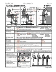
4.3.2 Workplace Measurement<br />
Recommended measurements <strong>for</strong> working height, distance to work area, leg room<br />
<strong>and</strong> area of free movement per workplace are provided in Appendix 4.2.<br />
4.3.3 Task Lighting<br />
a) The following light intensities are required:<br />
• 1,000 lux <strong>for</strong> testing <strong>and</strong> adjusting delicate components.<br />
• 1,500 lux <strong>for</strong> assembling delicate parts <strong>and</strong> electronics.<br />
b) Reflecting workstation surfaces should be avoided.<br />
4.3.4 Controls <strong>and</strong> Indicators<br />
Placement of Controls <strong>and</strong> Indicators should be within operator’s normal reach <strong>and</strong><br />
field of vision. See also Appendix 4.2.<br />
4.3.5 Lifting<br />
* In general, any manual lifting >30 lbs. should be avoided. All heavy or repetitive<br />
lifting (tools, fixture changes, loading, unloading) must be evaluated using the<br />
NIOSH lifting guide. If above the action limit (AL), mechanical lifts are required.<br />
The plant will specify the systems that may be used (supplier, make <strong>and</strong> model). It<br />
should be quoted separately.<br />
4.3.6 Access<br />
a) When a person has to reach a full arm’s length, clearance <strong>for</strong> the body shall be<br />
provided to allow both h<strong>and</strong>s to reach the tools without placing the operator in an<br />
uncom<strong>for</strong>table or hazardous position relative to the surrounding conditions. All<br />
tool changes must be accomplished with both feet of the operator on normal<br />
floor level.<br />
b) The layout of the workstation should provide easy access <strong>for</strong> maintenance,<br />
cleaning, housekeeping, material h<strong>and</strong>ling, etc.<br />
Mechanical Design - 4 - 6
BOSCH <strong>General</strong> <strong>Delivery</strong> <strong>Specifications</strong> <strong>for</strong> <strong>Machinery</strong> <strong>and</strong> <strong>Equipment</strong> Apr. 1, 2005<br />
4.4 Pneumatic Controls<br />
4.4.1 <strong>General</strong><br />
4.4.1.1 Non lubricated compressed air shall be used wherever possible.<br />
4.4.1.2 All types of pneumatic control logic are subject to approval by Project<br />
Engineer. Electrical logic controls are preferred.<br />
4.4.1.3 Pneumatic circuit should be designed to function at minimum 4.5 bar.<br />
6 bar (85 PSI) is st<strong>and</strong>ard plant pressure.<br />
Control voltage <strong>for</strong> solenoid air valves shall be 24V DC.<br />
4.4.2 <strong>Equipment</strong> Requirements<br />
4.4.3 Safety<br />
4.4.2.1 Components<br />
a) Filters, separators, pressure regulators, <strong>and</strong> dryers must be part<br />
of the pneumatic circuit. Automatic water dump traps shall be<br />
used to drain air line filters <strong>and</strong> lubricators.<br />
b) All air cylinders that bottom in rapid travel must be cushioned<br />
to prevent pounding. Deceleration valve shall be used when<br />
cylinder does not bottom in either direction.<br />
c) Lubricators shall be used only when approved by project<br />
engineer. If lubricators must be used, they shall be so mounted<br />
as to assure ample downstream lubrication to those parts being<br />
served by the lubricator.<br />
d) Air discharge to atmosphere shall be provided with mufflers of<br />
sufficient capacity to reduce noise readings to 80 dBA or less<br />
at point of discharge.<br />
4.4.3.1 The main air <strong>and</strong> hydraulic inlet valves should provide a quick means<br />
of shutting off the supply <strong>and</strong> exhausting the downstream system. It<br />
must be in easy reach of the operator <strong>and</strong> designed to be locked out in<br />
the closed position.<br />
Mechanical Design - 4 - 7
BOSCH <strong>General</strong> <strong>Delivery</strong> <strong>Specifications</strong> <strong>for</strong> <strong>Machinery</strong> <strong>and</strong> <strong>Equipment</strong> Apr. 1, 2005<br />
4.4.3.2 Independent of the energy (e.g. electric or pneumatic) used to control<br />
the pneumatic system, no danger shall result from switching on or off<br />
the energy supply, from energy breakdown as well as resumption of<br />
energy (unexpected or intended).<br />
4.4.3.3 To avoid rapid, uncontrolled movements when switching on systems<br />
that employ 3 position valves, a filling circuit/valve shall be used.<br />
4.4.3.4 Construction: Air receivers <strong>and</strong> surge tanks shall be designed:<br />
• To con<strong>for</strong>m to the ASME Unfired Pressure Vessel Code <strong>and</strong> to<br />
applicable governmental pressure vessel codes.<br />
• So that they cannot be dismantled while containing pressure.<br />
• With a separate port of adequate size <strong>for</strong> a safety relief valve.<br />
4.4.3.5 Receivers <strong>and</strong> Surge Tanks shall be permanently marked with<br />
outst<strong>and</strong>ing words reading “CAUTION PRESSURE VESSEL”.<br />
4.4.3.6 Safe Working Range of Adjustable Controls:<br />
Pressure <strong>and</strong> flow control components shall be constructed in a<br />
manner that prevents adjustment outside their safe working range. The<br />
manufacturer’s in<strong>for</strong>mation plate on pressure control components shall<br />
be marked to indicate their minimum <strong>and</strong> maximum pressure limits.<br />
4.4.3.7 Tamper-Resistant Protection:<br />
Where a hazard or damage may result if operating pressures are<br />
exceeded, tamper-resistant (e.g. internal positive stop, nonadjustable,<br />
etc.) overpressure protection must be provided.<br />
4.4.3.8 Cycle Restart:<br />
The equipment cycle may be manually restarted after an emergency<br />
operation, provided resumption does not create a hazard or cause<br />
damage to the equipment or to the work in process. Where continuing<br />
the cycle is not feasible, manual controls shall be provided <strong>for</strong><br />
returning the actuators affected by the emergency control to their cycle<br />
start or other preset position.<br />
4.4.3.9 Emergency Controls:<br />
Emergency controls shall be provided at each operator’s work station.<br />
Mechanical Design - 4 - 8
BOSCH <strong>General</strong> <strong>Delivery</strong> <strong>Specifications</strong> <strong>for</strong> <strong>Machinery</strong> <strong>and</strong> <strong>Equipment</strong> Apr. 1, 2005<br />
4.5 Lubrication<br />
4.6 Paint<br />
If technically possible, maintenance-free components shall be used. If not possible, lubrication<br />
points have to be easily accessible (without removing guards) <strong>and</strong> permanently tagged.<br />
Type of fluid <strong>and</strong> grease should be approved by <strong>Bosch</strong>. Attempts should be made to use<br />
lubricants stocked at <strong>Bosch</strong> sites.<br />
4.6.1 Paint being used must be resistant to oil <strong>and</strong> test fluid <strong>and</strong> also to synthetic coolants<br />
<strong>and</strong> any other consumable liquids with which the equipment may come in contact<br />
with during regular operation.<br />
4.6.2 Machine tool surfaces which come in contact with the workpiece, or surfaces which<br />
might be source of contamination shall not be painted. They might be constructed<br />
by using e.g. stainless steel, chromating, etc., in order to avoid rust or other<br />
degradation.<br />
4.6.3 All heat treat equipment surfaces exposed to high temperature shall be painted with<br />
heat resistant paint. Aluminum paint may be required.<br />
4.6.4 Colors:<br />
USE COLOR STANDARD<br />
<strong>Equipment</strong><br />
(See plant specific requirements, Section 10 - Attachments)<br />
Installations: Sprinkler Lines Red OSHA Red<br />
Gas Lines Yellow OSHA Yellow<br />
4.6.5 All paints shall be lead-free.<br />
(See Section 7 <strong>for</strong> Pre-Final Acceptance Checklist.)<br />
Mechanical Design - 4 - 9
BOSCH <strong>General</strong> <strong>Delivery</strong> <strong>Specifications</strong> <strong>for</strong> <strong>Machinery</strong> <strong>and</strong> <strong>Equipment</strong> Apr. 1, 2005<br />
SECTION 5 - ELECTRICAL DESIGN<br />
TABLE OF CONTENTS<br />
*<br />
*<br />
*<br />
*<br />
*<br />
*<br />
*<br />
Page<br />
5.1 St<strong>and</strong>ards ................................................................................................................5-2<br />
5.2 Control Systems Overview .....................................................................................5-2<br />
5.3 Documentation........................................................................................................5-2<br />
5.3.1...... Drawings....................................................................................................5-2<br />
5.3.2...... Software.....................................................................................................5-2<br />
5.4 Functional ...............................................................................................................5-2<br />
5.4.1...... Safety.........................................................................................................5-2<br />
5.4.2...... Manual Control ..........................................................................................5-2<br />
5.4.3...... Independent Control...................................................................................5-3<br />
5.4.4...... Diagnostics ................................................................................................5-3<br />
5.4.5...... Anti-Repeat................................................................................................5-3<br />
5.4.6...... Control Parameters/Values .........................................................................5-3<br />
5.4.7...... Bus Systems...............................................................................................5-3<br />
5.4.8...... Lamp Test..................................................................................................5-3<br />
5.4.9...... Cycle Counters...........................................................................................5-3<br />
5.5 <strong>Equipment</strong>...............................................................................................................5-3<br />
5.5.1...... Machine Voltage ........................................................................................5-3<br />
5.5.2...... Components ...............................................................................................5-3<br />
5.5.3...... Component Labeling ..................................................................................5-4<br />
5.5.4...... Controller Outputs......................................................................................5-4<br />
5.5.5...... Enclosures..................................................................................................5-4<br />
5.5.6...... Motors........................................................................................................5-5<br />
5.6 Wiring Methods ......................................................................................................5-5<br />
5.6.1...... Grounding..................................................................................................5-5<br />
5.6.2...... Test Points .................................................................................................5-5<br />
5.6.3...... Wire Termination, Labeling .......................................................................5-5<br />
5.6.4...... Splicing......................................................................................................5-6<br />
5.6.5...... Spare Wire .................................................................................................5-6<br />
5.6.6...... Wire Type ..................................................................................................5-6<br />
5.6.7...... Wire Colors................................................................................................5-6<br />
5.6.8...... Flexible Conduit.........................................................................................5-6<br />
5.7 Programmable Logic Controllers <strong>and</strong> Computers ...............................................5-6<br />
* 5.8 Data Management <strong>and</strong> Networking.......................................................................5-6<br />
5.8.1...... Infrastructure <strong>and</strong> Interfaces .......................................................................5-6<br />
5.8.2...... Virus Protection .........................................................................................5-7<br />
5.8.3...... Physical <strong>and</strong> Data Security.........................................................................5-7<br />
5.8.4...... Software.....................................................................................................5-7<br />
Electrical Design - 5 - 1
BOSCH <strong>General</strong> <strong>Delivery</strong> <strong>Specifications</strong> <strong>for</strong> <strong>Machinery</strong> <strong>and</strong> <strong>Equipment</strong> Apr. 1, 2005<br />
SECTION 5 - ELECTRICAL DESIGN<br />
5.1 St<strong>and</strong>ards<br />
All equipment shall con<strong>for</strong>m to the latest NFPA 70 (National Electric Code) <strong>and</strong> NFPA 79<br />
(Electrical St<strong>and</strong>ard <strong>for</strong> Industrial <strong>Machinery</strong>) unless otherwise stated in these specifications.<br />
5.2 Control Systems Overview<br />
A Control Systems Overview <strong>for</strong>m shall be completed when the job is quoted.<br />
(See Appendix 5.1)<br />
5.3 Documentation<br />
*<br />
5.3.1 Drawings<br />
All drawings shall be drawn with CAD <strong>and</strong> drawing files shall be provided in plant<br />
specific <strong>for</strong>mat (See plant specific requirements, Section 10 - Attachments). In<br />
addition, drawings shall also be provided in Adobe Acrobat pdf <strong>for</strong>mat.<br />
Electrical Drawings shall be “A” or “B” size (DIN Size A4 or A3).<br />
*<br />
5.3.2 Software<br />
5.4 Functional<br />
All software needed to use or modify any component of the machine shall be licensed<br />
<strong>and</strong> provided. All software shall be in English. Source code of all software developed<br />
under this purchase order shall be provided <strong>and</strong> becomes the property of <strong>Bosch</strong>.<br />
A functional plan describing sequential operation shall be provided <strong>for</strong> all machines.<br />
5.4.1 Safety<br />
Control of all devices shall be designed such that loss of power in any <strong>for</strong>m<br />
(electrical, pneumatic, hydraulic) shall not present a hazard to personnel or damage<br />
the equipment or work in process. No automatic restart shall occur when power is<br />
resumed.<br />
5.4.2 Manual Control<br />
Manual controls shall be provided <strong>for</strong> tool changing, setup <strong>and</strong> maintenance<br />
operation. The controls shall be interlocked to prevent machine or part damage.<br />
Electrical Design - 5 - 2
BOSCH <strong>General</strong> <strong>Delivery</strong> <strong>Specifications</strong> <strong>for</strong> <strong>Machinery</strong> <strong>and</strong> <strong>Equipment</strong> Apr. 1, 2005<br />
5.4.3 Independent Control<br />
Separate control systems shall be used <strong>for</strong> each individual machine.<br />
5.4.4 Diagnostics<br />
Diagnostic indication shall be provided <strong>for</strong> each possible state of the machine.<br />
5.4.5 Anti-Repeat<br />
On equipment where continuous consecutive cycling is not a normal condition, the<br />
controls shall be designed to prevent such operation.<br />
5.4.6 Control Parameters/Values<br />
Setup parameters which can affect the quality or the cycle time of the station shall be<br />
locked or password protected. Process values which can affect quality shall be<br />
monitored <strong>and</strong> should shut down the machine if not within tolerance.<br />
5.4.7 Field Bus Systems<br />
See plant specific requirements, Section 10 - Attachments.<br />
5.4.8 Lamp Test<br />
All lamps shall have a method of testing <strong>for</strong> defective bulbs.<br />
5.4.9 Cycle Counters<br />
5.5 <strong>Equipment</strong><br />
Both a non-resettable <strong>and</strong> a resettable cycle counter shall be included.<br />
5.5.1 Machine Voltage<br />
The primary voltage <strong>for</strong> machines shall be 480 VAC, 3φ, 60 Hz. Control voltage<br />
shall be regulated 24 VDC. Receptacles <strong>for</strong> 115 VAC shall be st<strong>and</strong>ard US<br />
grounded 3 prong (Some plants have specific requirements <strong>for</strong> machine voltage<br />
tolerances, see Section 10 - Attachments).<br />
5.5.2 Components<br />
*<br />
a) <strong>Equipment</strong> shall be constructed utilizing <strong>Bosch</strong> “Preferred Electrical<br />
Components” (See plant specific requirements, Section 10 - Attachments).<br />
b) Trans<strong>for</strong>mers <strong>and</strong> power supplies shall have 30% excess capacity.<br />
Electrical Design - 5 - 3
BOSCH <strong>General</strong> <strong>Delivery</strong> <strong>Specifications</strong> <strong>for</strong> <strong>Machinery</strong> <strong>and</strong> <strong>Equipment</strong> Apr. 1, 2005<br />
5.5.3 Component Labeling<br />
All functional <strong>and</strong> electrical components shall be permanently labeled with their<br />
corresponding schematic designation.<br />
5.5.4 Controller Outputs<br />
Controller outputs shall have individual over current protection <strong>for</strong> each circuit.<br />
5.5.5 Enclosures<br />
a) Expansion:<br />
Enclosures shall be designed with 20% expansion capability. This shall include<br />
but not be limited to space <strong>for</strong> terminal blocks, relays, breakers, starters,<br />
wireways, <strong>and</strong> controller I/O.<br />
b) Lighting:<br />
Lighting controlled by a door switch shall be provided on enclosures over 0.425<br />
m 3 (15 cu. ft.).<br />
*<br />
c) Programmable Devices:<br />
All enclosures containing a programmable device shall have a 115 VAC GFCI,<br />
receptacle labeled “For programming device only”.<br />
A programming interface shall be readily accessible.<br />
d) Connectors:<br />
Wiring to enclosures not mounted on the machine shall have connectors. Plugs<br />
<strong>and</strong> sockets must be permanently labeled (See plant specific requirements,<br />
Section 10 - Attachments).<br />
e) Location:<br />
* f) Safety:<br />
Bottom of enclosures shall be a minimum of 100 mm above the floor. The<br />
control enclosure should be positioned so that the machine can be observed<br />
while working in the enclosure.<br />
Minimum working space in front of electrical enclosures shall be maintained.<br />
See Section 9 - Appendix 5.2 <strong>for</strong> more detail.<br />
Electrical cabinet doors shall be removable or able to open at least 90 degrees.<br />
Electrical Design - 5 - 4
BOSCH <strong>General</strong> <strong>Delivery</strong> <strong>Specifications</strong> <strong>for</strong> <strong>Machinery</strong> <strong>and</strong> <strong>Equipment</strong> Apr. 1, 2005<br />
5.5.6 Motors<br />
5.6 Wiring Methods<br />
AC motors shall be High Energy Efficient TEFC, 480 VAC, 3φ, 60 Hz. All motors<br />
25hp <strong>and</strong> above shall have continuous conductors from the control enclosure to the<br />
motor. No intermediate terminations are permitted. Such motors shall also have<br />
power factor corrected to above 90%.<br />
5.6.1 Grounding<br />
Trans<strong>for</strong>mers <strong>and</strong> power supplies shall have their neutral or common conductors<br />
grounded at the source. If special earth grounds are necessary, this shall be specified<br />
by the supplier during initial design review <strong>and</strong> detailed in the installation<br />
specifications.<br />
5.6.2 Test Points<br />
All control <strong>and</strong> power wiring shall have readily accessible test points in the control<br />
enclosures.<br />
5.6.3 Wire Termination, Labeling<br />
* For screw or screw clamp terminations, all wire ends shall be fitted with ferrules or<br />
crimp connectors. All wires shall be labeled, terminated <strong>and</strong> identified in the<br />
electrical prints. Multiple-device control panels shall be equipped with terminal<br />
blocks or attachment plugs <strong>and</strong> receptacles <strong>for</strong> all outgoing control conductors.<br />
Wiring directly to the terminal connection points on input or output modules of<br />
programmable electronic systems shall be permitted.<br />
Wire labeling method shall be specified by the customer. The machine builder is<br />
responsible <strong>for</strong> determining customer preference. Wires shall be labeled at each end<br />
either with wire numbers or termination labels. Wire numbers or termination<br />
labels shall be used exclusively.<br />
When wire numbers are used, each individual wire shall have the same<br />
number at all termination points. Terminal block labels shall match the wire<br />
numbers. Wires connecting to controller I/O shall be labeled with an I <strong>for</strong><br />
Inputs <strong>and</strong> Q <strong>for</strong> Outputs followed by the I/O address, dropping any<br />
punctuation <strong>and</strong> adding leading zeros as appropriate. For example, the wire<br />
that connects to output Q2.4 should be labeled "Q024".<br />
When wire termination labels are used, the termination label shall identify the<br />
terminal name where the wire should terminate. Example: The wires connected<br />
to terminal A1 of –K911A shall be labeled –K911A:A1<br />
Electrical Design - 5 - 5
BOSCH <strong>General</strong> <strong>Delivery</strong> <strong>Specifications</strong> <strong>for</strong> <strong>Machinery</strong> <strong>and</strong> <strong>Equipment</strong> Apr. 1, 2005<br />
5.6.4 Splicing<br />
Splicing is prohibited. Wiring shall run uninterrupted from terminal to terminal.<br />
5.6.5 Spare Wire<br />
A minimum of 15% spare wire shall exist in each wireway that is external to an<br />
enclosure.<br />
*<br />
5.6.6 Wire Type<br />
Wire shall be str<strong>and</strong>ed copper. Wire jacketing shall be type MTW <strong>for</strong> wires not<br />
leaving electrical enclosures. Elsewhere, wire jacketing shall be compatible with the<br />
associated fluids <strong>and</strong> working environment:<br />
- Type PUR: <strong>for</strong> areas with coolant, oil <strong>and</strong> diesel/gasoline calibration type fluids<br />
(e.g. VISCOR)<br />
- Type PVC: <strong>for</strong> brake fluid areas<br />
* 5.6.7 Wire Colors<br />
See plant specific requirements, Section 10 - Attachments.<br />
5.6.8 Flexible Conduit<br />
Each section of flexible conduit shall be kept to a maximum of 1 meter.<br />
5.7 Programmable Logic Controllers <strong>and</strong> Computers<br />
See plant specific requirements, Section 10 - Attachments.<br />
*<br />
5.8 Data Management <strong>and</strong> Networking<br />
The <strong>Bosch</strong> Corporate Network (BCN) is a private, global data network which interconnects<br />
all Robert <strong>Bosch</strong> GmbH sites throughout the world. The network has been designed to<br />
provide fast, secure, <strong>and</strong> reliable data transmission to all sites. To this end, it is requested<br />
that all vendors adhere to the BCN st<strong>and</strong>ards wherever possible.<br />
5.8.1 Infrastructure <strong>and</strong> Interfaces<br />
The physical connection to the BCN is generally provided via RJ-45 jacks installed<br />
as required near the equipment. These network drops will be terminated external to<br />
the equipment such that cable infrastructure troubleshooting or rewiring can be done<br />
without requiring access into the machine enclosures.<br />
Managed Cisco routers <strong>and</strong> switches comprise the backbone of the corporate<br />
network. To ensure network integrity <strong>and</strong> monitoring down to each networked<br />
device, manageable Cisco switches should be used rather than simple network hubs.<br />
Your <strong>Bosch</strong> representative should be able to obtain recommended equipment model<br />
numbers.<br />
Electrical Design - 5 - 6
BOSCH <strong>General</strong> <strong>Delivery</strong> <strong>Specifications</strong> <strong>for</strong> <strong>Machinery</strong> <strong>and</strong> <strong>Equipment</strong> Apr. 1, 2005<br />
TCP/IP over Ethernet is the st<strong>and</strong>ard protocol. Some sites may require specific<br />
subnetting or support <strong>for</strong> other management protocols <strong>for</strong> manufacturing devices, so<br />
be sure to check with your <strong>Bosch</strong> representative. Site-specific static IP addresses can<br />
be assigned by the local in<strong>for</strong>mation technology group or equivalent responsible<br />
group.<br />
5.8.2 Virus Protection<br />
One of the greatest network security threats are viruses. The BCN has multi-layered<br />
anti-virus protection starting at company firewalls cascading down to each desktop<br />
computer. Anti-virus engines on desktop computers are updated daily with the latest<br />
virus definition files <strong>and</strong> anti-virus scans are scheduled to run automatically on these<br />
computers. <strong>Bosch</strong> requires that vendors evaluate the vulnerability of their equipment<br />
to computer viruses <strong>and</strong> worms. Reasonable safeguards <strong>and</strong>/or software updates<br />
should be part of the preventative maintenance recommendations <strong>for</strong> the equipment.<br />
Due to throughput <strong>and</strong> per<strong>for</strong>mance requirements of some manufacturing computing<br />
systems, real-time anti-virus scanning may not be possible. In this case,<br />
manufacturing computing systems may be isolated from the general-use BCN using<br />
Virtual Local Area Networks (VLANs). VLANs allow specific traffic flow from<br />
manufacturing lines’ data concentrators through to other systems located on the<br />
general-use BCN. In the event of a virus outbreak emanating from a manufacturing<br />
computer system, all traffic flow from that manufacturing system to the general-use<br />
BCN can be quickly stopped until the source of the virus is located <strong>and</strong> eradicated.<br />
5.8.3 Physical <strong>and</strong> Data Security<br />
Data confidentiality is extremely important to <strong>Bosch</strong>. Company policy states that<br />
unauthorized data transmission of any nature to external parties is strictly <strong>for</strong>bidden.<br />
To protect that policy, modems are not permitted on any computer connected to the<br />
BCN. If remote dial-up access is required, alternate techniques will be employed<br />
using existing <strong>Bosch</strong> st<strong>and</strong>ards <strong>and</strong> safeguards.<br />
Removable data storage devices (i.e., external hard drives, USB memory sticks, etc.)<br />
are not normally permitted on computers connected to the BCN because these<br />
devices can be used to transport sensitive data off the premises. Specific exceptions<br />
to the removable storage restrictions can be made when alternate procedures are<br />
instituted to ensure the security of <strong>Bosch</strong> corporate data.<br />
5.8.4 Software<br />
It is also the vendor’s responsibility to ensure that any third-party software, included<br />
as part of the finished equipment, is properly <strong>and</strong> legally licensed. <strong>Bosch</strong> may<br />
request physical proof of proper licensing or transferability.<br />
Any third-party software support agreements must be clearly documented so that all<br />
parties underst<strong>and</strong> the terms. Where applicable, all software components <strong>and</strong> their<br />
interactions should be documented thoroughly <strong>and</strong> included as part of the operating<br />
<strong>and</strong> maintenance instructions <strong>for</strong> the equipment.<br />
(See Section 7 <strong>for</strong> Pre-Final Acceptance Checklist.)<br />
Electrical Design - 5 - 7
BOSCH <strong>General</strong> <strong>Delivery</strong> <strong>Specifications</strong> <strong>for</strong> <strong>Machinery</strong> <strong>and</strong> <strong>Equipment</strong> Apr. 1, 2005<br />
SECTION 6 - QUALITY STANDARDS & RUN-OFF CONDITIONS<br />
TABLE OF CONTENTS<br />
6.1 <strong>General</strong> ...................................................................................................................6-2<br />
6.2 Guidelines <strong>for</strong> Statistical Evaluation.....................................................................6-2<br />
* 6.3 Gage, Process <strong>and</strong> Machine Capability ................................................................6-3<br />
6.4 Gage Scale <strong>and</strong> Signal Output...............................................................................6-3<br />
* 6.5 <strong>Equipment</strong> Effectiveness <strong>and</strong> Durability Demonstrations...................................6-4<br />
6.6 Run-off Conditions ................................................................................................6-4<br />
6.6.1 Process Data or Set-up Sheet .......................................................................6-4<br />
6.6.2 Adjustment Frequency Limitation................................................................6-4<br />
* 6.7 Software Validation ...............................................................................................6-5<br />
Page<br />
Quality St<strong>and</strong>ards & Run-Off Conditions - 6 - 1
BOSCH <strong>General</strong> <strong>Delivery</strong> <strong>Specifications</strong> <strong>for</strong> <strong>Machinery</strong> <strong>and</strong> <strong>Equipment</strong> Apr. 1, 2005<br />
6.1 <strong>General</strong><br />
SECTION 6 - QUALITY STANDARDS & RUN-OFF CONDITIONS<br />
6.1.1 It is the policy of the Robert <strong>Bosch</strong> Corporation to conduct a pre-acceptance<br />
evaluation of new machines <strong>and</strong> test st<strong>and</strong>s <strong>for</strong> proper quality of operation at the<br />
equipment supplier’s facility by a <strong>Bosch</strong> Project Engineer prior to authorizing<br />
shipment. The final acceptance evaluation will be conducted at the <strong>Bosch</strong> facility<br />
under plant operating conditions. The same or better quality level achieved during<br />
pre-acceptance trials must be achieved during final acceptance trials.<br />
6.1.2 All quality requirements outlined in the Purchase Order, its supplements <strong>and</strong><br />
supporting documents (specifications, st<strong>and</strong>ards, drawings, etc.) must meet the<br />
evaluation criteria stated below or as indicated in Appendices 6.<br />
6.1.3 A pre-acceptance evaluation will be conducted only after the equipment supplier has<br />
presented data or sample parts indicating that the equipment meets the requirements<br />
of the Purchase Order.<br />
6.1.4 All pre- <strong>and</strong> final acceptance trials shall be witnessed or conducted by <strong>Bosch</strong><br />
personnel using <strong>Bosch</strong>-supplied parts. Supporting equipment, gages, calculators, etc.,<br />
<strong>and</strong> labor shall be provided by the supplier unless otherwise agreed upon. Acceptance<br />
plan, method of measurement <strong>and</strong> data record <strong>for</strong>mat must be approved by <strong>Bosch</strong>.<br />
6.1.5 For pre-acceptance trials, gage calibration may be certified by manufacturers’ data<br />
sheets <strong>and</strong> calibration data records. For final acceptance, calibration certification<br />
must be current.<br />
6.2 Guidelines <strong>for</strong> Statistical Evaluation<br />
6.2.1 As a general rule, quality of operation will be evaluated by statistical methods.<br />
Specific characteristics to be examined during pre- <strong>and</strong> final acceptance trials shall<br />
be provided to the equipment supplier as part of the equipment specification.<br />
6.2.2 Parts to be provided by <strong>Bosch</strong> <strong>for</strong> pre- <strong>and</strong> final acceptance trials will be production<br />
parts, pre-qualified <strong>for</strong> characteristics that could influence capability studies.<br />
6.2.3 See Appendix 6.1 <strong>for</strong> a Sample Size table which provides guidelines <strong>for</strong> determining<br />
numbers of parts to be used or manufactured during acceptance trials. Non-st<strong>and</strong>ard<br />
sampling plans <strong>for</strong> acceptance are to be specified in the Purchase Order.<br />
6.2.4 Where more than one part is produced simultaneously or <strong>for</strong> multi-spindle/station<br />
machines, the total production is to be divided equally among the work piece<br />
locations. Parts are to be identified with the location from which they came.<br />
Quality St<strong>and</strong>ards & Run-Off Conditions - 6 - 2
BOSCH <strong>General</strong> <strong>Delivery</strong> <strong>Specifications</strong> <strong>for</strong> <strong>Machinery</strong> <strong>and</strong> <strong>Equipment</strong> Apr. 1, 2005<br />
6.3 Gage, Process <strong>and</strong> Machine Capability<br />
6.3.1 Gage, process <strong>and</strong> machine capability shall be demonstrated using appropriate<br />
procedures (See plant specific requirements, Section 10 - Attachments).<br />
* 6.3.2 The following capability requirements apply unless otherwise agreed upon in the<br />
Purchase Order:<br />
(a) Gage Capability:<br />
(i) If a st<strong>and</strong>ard gage Repeatability <strong>and</strong> Reproducibility (R&R) test is used,<br />
Study Variation / Tolerance shall be 12.5.<br />
(This calculation should be done using the Shainin Red X Tracker ()<br />
software, not by h<strong>and</strong>.)<br />
The ISOPlot(sm) is valid only <strong>for</strong> cases where the operator does not<br />
influence the measurement result. If the operator can affect the<br />
measurement, e.g., use of a h<strong>and</strong>-held depth gage, consult the AIAG<br />
Measurement Systems Analysis manual <strong>and</strong> plant-specific requirements<br />
<strong>for</strong> st<strong>and</strong>ard R&R procedures.<br />
(b) Machine capability: Cmk shall be >1.67; <strong>and</strong><br />
(c) Process capability: Cpk shall be > 1.33.<br />
Note:<br />
To be valid, Cmk <strong>and</strong> Cpk calculations must be based on measurements that<br />
are statistically stable <strong>and</strong> that are approximately normally distributed.<br />
Statistical stability must be verified be<strong>for</strong>e proceeding further. (See AIAG<br />
SPC Reference Manual.) If non-normality is confirmed, use an appropriate<br />
data trans<strong>for</strong>mation method to obtain an equivalent normal distribution from<br />
which reliable Cmk <strong>and</strong> Cpk values may be calculated.<br />
6.4 Gage Scale <strong>and</strong> Signal Output<br />
6.4.1 The least count of electrical gages or least division of mechanical gages shall be less<br />
than or equal to one-tenth OF THE SMALLEST PART TOLERANCE to be<br />
measured. Special consideration may be given to gaging used to measure<br />
characteristics with tolerances less than 0.010 mm.<br />
6.4.2 All gages shall display a variable data result unless otherwise specified. Electronic<br />
gages which measure pertinent product dimensions shall include an appropriate data<br />
output port (preferably RS232) with the capability <strong>for</strong> remote access <strong>for</strong> recording<br />
functional <strong>and</strong> quality data. Questions regarding what dimensions are pertinent shall<br />
Quality St<strong>and</strong>ards & Run-Off Conditions - 6 - 3
BOSCH <strong>General</strong> <strong>Delivery</strong> <strong>Specifications</strong> <strong>for</strong> <strong>Machinery</strong> <strong>and</strong> <strong>Equipment</strong> Apr. 1, 2005<br />
be resolved prior to design approval. In general, all parameters useful in analyzing<br />
machine per<strong>for</strong>mance <strong>and</strong> quality of operation should be monitored.<br />
6.5 <strong>Equipment</strong> Effectiveness <strong>and</strong> Durability Demonstrations<br />
6.5.1 The minimum acceptable Technical Availability during production shall be 95% (e.g.<br />
downtime related to issues <strong>for</strong> which the manufacturer is responsible not to exceed<br />
5%) unless otherwise agreed upon <strong>and</strong> specified in the Purchase Order. Calculations<br />
shall be based on Appendix 6.2 guidelines (VDI 3423).<br />
* 6.5.2 All part-type changeovers (last good part to first good part) shall be per<strong>for</strong>med in<br />
accordance with the <strong>Bosch</strong> Production System (BPS) guidelines (
BOSCH <strong>General</strong> <strong>Delivery</strong> <strong>Specifications</strong> <strong>for</strong> <strong>Machinery</strong> <strong>and</strong> <strong>Equipment</strong> Apr. 1, 2005<br />
b) The average number of unplanned machine cycle interruptions, including<br />
adjustments, shall not exceed once in 1.5 hours with the machine operating at<br />
100% capacity.<br />
c) If unplanned interruptions are required more often than allowed above, the<br />
cause(s) must be identified <strong>and</strong> resolved. Unless waived by the Project<br />
Engineer, the production run portion of a trial must be repeated after corrective<br />
action is completed.<br />
d) A minimum of one change per tool, following the established set up procedure,<br />
should occur during the run-off.<br />
6.7 Software Validation<br />
* 6.7.1 All modes <strong>and</strong> features of software operation, including output of printed reports,<br />
shall be demonstrated. Where applicable, operation on the plant network <strong>and</strong> remote<br />
access must be demonstrated during final acceptance trials. Arrangements <strong>for</strong><br />
remote access shall comply with the requirements of Section 5.8, Data Management<br />
<strong>and</strong> Networking. Project engineers should contact their local RBNA/CIT group to<br />
investigate the feasibility of using the <strong>Bosch</strong> Remote Access System (RAS) to meet<br />
the project needs.<br />
6.7.2 Software that processes measurement system data or sets machine operating<br />
conditions which cannot be observed visually must be validated by an independent<br />
means. For such cases, equipment suppliers shall include appropriate test plan steps<br />
that independently demonstrate the proper operation of the software. This includes<br />
verification of calculation implementation.<br />
(See Section 7 <strong>for</strong> Pre-Final Acceptance Checklist.)<br />
Quality St<strong>and</strong>ards & Run-Off Conditions - 6 - 5
Robert <strong>Bosch</strong> Corporation<br />
SECTION 7 – PRE / FINAL ACCEPTANCE CHECKLIST<br />
TABLE OF CONTENTS<br />
7.1 <strong>General</strong>....................................................................................................................7-2<br />
7.2 Checklist..................................................................................................................7-3<br />
Page<br />
CF06790006.doc Revision: 1, 4/1/05 Originator: ChW/BPS-LS W.Hasper Page 1 of 14
Robert <strong>Bosch</strong> Corporation<br />
<strong>Bosch</strong> <strong>General</strong> <strong>Delivery</strong> <strong>Specifications</strong> <strong>for</strong> <strong>Machinery</strong> <strong>and</strong> <strong>Equipment</strong><br />
7.1 <strong>General</strong><br />
7.1.1 All tests conducted at equipment supplier are preliminary acceptance tests.<br />
Final acceptance will always be conducted at <strong>Bosch</strong>.<br />
7.1.2 <strong>Bosch</strong> will provide qualified components <strong>for</strong> acceptance. Provision <strong>for</strong><br />
gauges/measurement equipment <strong>and</strong> personnel to be coordinated with the<br />
project engineer.<br />
7.1.3 Evaluation of quality will be done with statistical method, when applicable,<br />
described in Section 6.<br />
7.1.4 Acceptance shall be based on the production result. Per<strong>for</strong>mance data <strong>and</strong><br />
process time to be verified <strong>and</strong> documented.<br />
Instructions:<br />
<strong>Bosch</strong> Project Engineer/Leader is responsible <strong>for</strong> the completion of the <strong>Machinery</strong> & <strong>Equipment</strong><br />
pre-acceptance checklist.<br />
The first “Yes” column P/A is <strong>for</strong> Pre-Acceptance; the second “Yes” column F/A is <strong>for</strong> Final<br />
Acceptance.<br />
Items that are Not Applicable shall be recorded as N/A in the comments section. All items that<br />
have checks in the “No” column require corrective action unless deviations have been<br />
authorized.<br />
CF06790006 .doc Revision: 1, 4/1/05 Originator: ChW/BPS-LS W.Hasper Page 2 of 14
Robert <strong>Bosch</strong> Corporation<br />
Project:<br />
Project Leader:<br />
Date:<br />
GDS Section 1:<br />
<strong>General</strong> Procedure<br />
1.1 Has supplier agreed to<br />
con<strong>for</strong>m to “Robert <strong>Bosch</strong><br />
<strong>General</strong> <strong>Delivery</strong><br />
Specification” dated: ?<br />
1.2 Are all documentation,<br />
(drawings, service manuals,<br />
etc.) available <strong>and</strong> in<br />
English?<br />
1.3 Are the quoted conditions<br />
Ref.<br />
GDS/<br />
Other<br />
1.2.2.9<br />
1.2.2.d<br />
8.1.1<br />
1.2.1<br />
achieved<br />
1.3.1 ! Cycle Time? Quote<br />
1.3.2 ! Machine Utilization? 6.5.1<br />
1.3.3 ! Changeover Time Min.? 6.5.2<br />
1.3.4 ! Production Rate Quote<br />
Pieces/Hr.?<br />
1.3.5 ! Tool Life? Quote<br />
1.3.6 ! Gage Capability? 6.3.2<br />
1.3.7 ! Process Capability? 6.3.2<br />
1.3.8 ! Facility Utilities (i.e.<br />
power, steam, air, etc.)?<br />
2.2.3.e<br />
P/<br />
A<br />
Yes<br />
F/<br />
A<br />
Yes<br />
No<br />
Comments/Test Results<br />
or N/A<br />
Date<br />
Needed<br />
Section 2: N/A<br />
GDS Section 3:<br />
Safety & Health St<strong>and</strong>ards<br />
Emergency Stop<br />
3.1 Are Emergency Stop buttons<br />
<strong>for</strong> electrical, pneumatic <strong>and</strong><br />
hydraulic systems accessible<br />
<strong>and</strong> properly labeled?<br />
3.2 Does Emergency Stop<br />
function <strong>and</strong> prevent<br />
additional movement?<br />
3.3 Does Emergency Stop<br />
require Manual Release <strong>and</strong><br />
pushing the Start Button <strong>for</strong><br />
the machine to restart?<br />
Ref.<br />
GDS/<br />
Other<br />
OSHA<br />
1910.212<br />
OSHA<br />
1910.212<br />
OSHA<br />
1910.212<br />
P/<br />
A<br />
Yes<br />
F/<br />
A<br />
Yes<br />
No<br />
Comments/Test Results<br />
or N/A<br />
Date<br />
Needed<br />
CF06790006 .doc Revision: 1, 4/1/05 Originator: ChW/BPS-LS W.Hasper Page 3 of 14
Robert <strong>Bosch</strong> Corporation<br />
GDS Section 3<br />
Safety & Health St<strong>and</strong>ards<br />
3.4 Is Emergency Stop located<br />
within close reach of<br />
operator <strong>and</strong>/or technician<br />
near point of operation?<br />
Machine Guarding<br />
3.5 Are all hazard areas guarded<br />
(push, stroke, capture,<br />
retract, clip <strong>and</strong> squeeze<br />
areas, sharp edges, hot/cold<br />
surfaces):<br />
3.5.1 ! Rotating shafts are<br />
enclosed?<br />
3.5.2 ! Belts, chains, etc., are<br />
enclosed?<br />
3.5.3 ! All pinch points<br />
guarded?<br />
3.6 Are guards clear where<br />
viewing is required?<br />
3.7 Are guards not easily<br />
removable by operator?<br />
3.8 Are guards <strong>for</strong> setup<br />
interlocked <strong>and</strong> not easy to<br />
defeat?<br />
3.9 Are protective barriers<br />
installed to protect other<br />
associates from flying<br />
objects (e.g. milling,<br />
grinding)?<br />
Controls<br />
3.10 Two h<strong>and</strong> control: Is check<br />
function, anti tie-down, anti<br />
repeat, distance acceptable?<br />
3.11 Are manual controls<br />
inoperative in automatic<br />
cycle?<br />
3.12 Are all instructions/labels in<br />
English?<br />
3.13 Are light barriers, light<br />
curtains, safety mats, etc.,<br />
verified <strong>for</strong> proper<br />
operation?<br />
Ref.<br />
GDS/<br />
Other<br />
OSHA<br />
1910.212<br />
OSHA<br />
1910.212<br />
OSHA<br />
1910.212<br />
OSHA<br />
1910.212<br />
OSHA<br />
1910.212<br />
OSHA<br />
1910.212<br />
OSHA<br />
1910.212<br />
OSHA<br />
1910.212<br />
OSHA<br />
1910.212<br />
OSHA<br />
1910.217<br />
P/<br />
A<br />
Yes<br />
F/<br />
A<br />
Yes<br />
No<br />
Comments/Test Results<br />
or N/A<br />
Date<br />
Needed<br />
CF06790006 .doc Revision: 1, 4/1/05 Originator: ChW/BPS-LS W.Hasper Page 4 of 14
Robert <strong>Bosch</strong> Corporation<br />
GDS Section 3<br />
Safety & Health St<strong>and</strong>ards<br />
3.14 Do all safety switches/<br />
protective gates operate<br />
properly?<br />
3.15 Are all safety door interlocks<br />
verified to operate properly?<br />
3.16 Does the exhaust system<br />
operate properly (must stop/<br />
must not stop) if emergency<br />
stop is activated?<br />
3.17 Are machine controls<br />
accessible <strong>and</strong> away from<br />
revolving spindle, moving<br />
tools or other hazards?<br />
3.18 Is control panel access<br />
adequate with no blockage?<br />
3.19 Are general operating<br />
controls configured <strong>for</strong> safe<br />
operation?<br />
3.20 Are there interlocks <strong>for</strong> point<br />
of operation guarding?<br />
Labeling<br />
3.21 Are the following labels<br />
posted (in English):<br />
3.21.1 ! Danger Signs?<br />
3.21.2 ! Caution Signs?<br />
3.21.3 ! Confined Space?<br />
3.21.4 ! Notice Signs?<br />
3.21.5 ! Safety Instructions?<br />
3.21.6 ! Hazardous Materials?<br />
3.21.7 ! Utilities?<br />
3.21.8 ! Fluids <strong>and</strong> Lubricants?<br />
Lockout/Tagout (LO/TO)<br />
3.22 Are lock-out devices<br />
provided <strong>for</strong> all utility<br />
shutoffs (Pneumatic,<br />
hydraulic <strong>and</strong> electrical<br />
systems)?<br />
Ref.<br />
GDS/<br />
Other<br />
3.4.3<br />
OSHA<br />
1910.212<br />
OSHA<br />
1910.212<br />
OSHA<br />
1910.<br />
1200<br />
3.2.2<br />
P/<br />
A<br />
Yes<br />
F/<br />
A<br />
Yes<br />
No<br />
Comments/Test Results<br />
or N/A<br />
Date<br />
Needed<br />
CF06790006 .doc Revision: 1, 4/1/05 Originator: ChW/BPS-LS W.Hasper Page 5 of 14
Robert <strong>Bosch</strong> Corporation<br />
GDS Section 3<br />
Safety & Health St<strong>and</strong>ards<br />
HAZCOM<br />
3.23 Are MSDS’s available <strong>and</strong><br />
in English <strong>for</strong> all associated<br />
hazardous materials?<br />
3.24 Is safe storage provided <strong>for</strong><br />
all hazardous materials?<br />
3.25 Are flammable liquids in<br />
metal (OSHA approved)<br />
safety containers? Is<br />
grounding provided?<br />
<strong>General</strong><br />
3.26 Is potential oil & coolant<br />
leakage controlled?<br />
3.27 Have all operational hazards<br />
been identified (Job Safety<br />
Hazard Analysis)?<br />
3.28 Have special requirements<br />
<strong>for</strong> Division I Class I areas<br />
been addressed?<br />
3.29 Are sensors provided <strong>for</strong><br />
Division I Class I areas?<br />
Sound<br />
3.30 Does sound level not exceed<br />
80 dB(A) under normal<br />
operating conditions?<br />
Lasers<br />
3.31 Does laser comply with all<br />
requirements of ANSI<br />
Z136.1 Safe Use of Lasers?<br />
3.32 Is laser labeled, classified<br />
<strong>and</strong> certified?<br />
Robotic Operations:<br />
3.33 Do robotic operations<br />
comply with ANSI/RIA<br />
R15.06 dated ?<br />
3.34 Are all power disconnects<br />
<strong>and</strong> interlocks installed as<br />
required?<br />
3.35 Have all mechanical stops<br />
<strong>and</strong> range of motion stops<br />
been verified?<br />
3.36 Is there full envelope<br />
guarding?<br />
Ref.<br />
GDS/<br />
Other<br />
3.4.1<br />
OSHA<br />
1910.106<br />
3.4.1.f<br />
OSHA<br />
1910.119<br />
OSHA<br />
1910.307<br />
OSHA<br />
1910.307<br />
3.3<br />
3.2.6<br />
3.2.6<br />
3.2.4<br />
R15.06<br />
R15.06<br />
R15.06<br />
P/<br />
A<br />
Yes<br />
F/<br />
A<br />
Yes<br />
No<br />
Comments/Test Results<br />
or N/A<br />
Date<br />
Needed<br />
CF06790006 .doc Revision: 1, 4/1/05 Originator: ChW/BPS-LS W.Hasper Page 6 of 14
Robert <strong>Bosch</strong> Corporation<br />
GDS Section 4 –<br />
Mechanical Design Ergonomics<br />
4.1 Are workplace dimensions<br />
according to the <strong>Bosch</strong><br />
Workplace Measurement<br />
specifications?<br />
4.2 Is task lighting adequate, no<br />
glare?<br />
4.3 Are all secondary tasks at<br />
proper working heights<br />
(actuating or reading<br />
controls, h<strong>and</strong>ling parts bins,<br />
etc.)?<br />
4.4 Are all lifting tasks within<br />
NIOSH limits (changing of<br />
tools, fixtures, bins, etc.)?<br />
4.5 Are lifting aids provided <strong>for</strong><br />
heavy items?<br />
4.6 Is maximum lifting weight<br />
30 lbs.?<br />
4.7 Is the following assessed:<br />
4.7.1 ! Improper/unnecessary<br />
lifting?<br />
4.7.2 ! Repetitive motions?<br />
4.7.3 ! Operator posture?<br />
4.8 Is accessibility <strong>for</strong> material<br />
h<strong>and</strong>ling, adjusting,<br />
maintenance, <strong>and</strong> cleaning<br />
adequate?<br />
Ref.<br />
GDS/<br />
Other<br />
4.3.2<br />
4.3.3<br />
4.3.4<br />
4.3.5<br />
4.3.5<br />
4.3.5<br />
4.3.6.b<br />
P/<br />
A<br />
Yes<br />
F/<br />
A<br />
Yes<br />
No<br />
Comments/Test Results<br />
or N/A<br />
Date<br />
Needed<br />
GDS Section 5:<br />
Electrical Design<br />
5.1 Are electrical drawings<br />
created with CAD <strong>and</strong><br />
provided in plant specific<br />
<strong>for</strong>mat <strong>and</strong> also in Adobe<br />
Acrobat pdf <strong>for</strong>mat?<br />
5.2 Are electrical drawings<br />
provided on paper in “A”,<br />
“B”, “DIN A4” or “DIN A3”<br />
size?<br />
Ref.<br />
GDS/<br />
Other<br />
5.3.1<br />
5.3.1<br />
P/<br />
A<br />
Yes<br />
F/<br />
A<br />
Yes<br />
No<br />
Comments/Test Results<br />
or N/A<br />
Date<br />
Needed<br />
CF06790006 .doc Revision: 1, 4/1/05 Originator: ChW/BPS-LS W.Hasper Page 7 of 14
Robert <strong>Bosch</strong> Corporation<br />
Ref.<br />
GDS Section 5:<br />
GDS/<br />
Electrical Design<br />
Other<br />
5.3 Can <strong>Bosch</strong> make changes to 5.3.2<br />
all software?<br />
5.4 Is a functional plan<br />
5.4<br />
provided?<br />
5.5 Are controls designed so that 5.4.1<br />
loss of power (electrical,<br />
pneumatic, hydraulic) does<br />
not present a hazard to<br />
personnel or damage to<br />
equipment or damage to<br />
work in process?<br />
5.6 Are manual controls<br />
5.4.2<br />
provided <strong>and</strong> interlocked to<br />
prevent damage to machine<br />
or work in process?<br />
5.7 Are separate control systems 5.4.3<br />
used <strong>for</strong> each individual<br />
machine?<br />
5.8 Do machine controls include 5.4.4<br />
diagnostic indication <strong>for</strong> all<br />
machine states?<br />
5.9 Are abnormal continuous 5.4.5<br />
consecutive machine cycles<br />
prevented?<br />
5.10 Do passwords limit access to 5.4.6<br />
parameters?<br />
5.11 Do out of tolerance process 5.4.6<br />
values cause the machine to<br />
stop?<br />
5.12 Do field bus systems meet 5.4.7<br />
plant specific requirements?<br />
5.13 Can all lamps be tested? 5.4.8<br />
5.14 Are cycle counters present? 5.4.9<br />
5.15 Is input power 480 VAC, 3 5.5.1<br />
phase 60 Hz.?<br />
5.16 Is control voltage regulated 5.5.1<br />
24 VDC?<br />
5.17 Are receptacles <strong>for</strong> 115 VAC 5.5.1<br />
st<strong>and</strong>ard US grounded 3<br />
prong?<br />
P/<br />
A<br />
Yes<br />
F/<br />
A<br />
Yes<br />
No<br />
Comments/Test Results<br />
or N/A<br />
Date<br />
Needed<br />
CF06790006 .doc Revision: 1, 4/1/05 Originator: ChW/BPS-LS W.Hasper Page 8 of 14
Robert <strong>Bosch</strong> Corporation<br />
GDS Section 5:<br />
Electrical Design<br />
5.18 Do machine voltages comply<br />
with plant specific<br />
tolerances?<br />
5.19 Is equipment built with plant<br />
specific "Preferred Electrical<br />
Components"?<br />
5.20 Are control trans<strong>for</strong>mers <strong>and</strong><br />
power supplies sized 30%<br />
above maximum load?<br />
5.21 Are functional <strong>and</strong> electrical<br />
components permanently<br />
labeled with their<br />
corresponding schematic<br />
designation?<br />
5.22 Do controller output circuits<br />
have individual circuit<br />
protection?<br />
5.23 Do enclosures have room <strong>for</strong><br />
20% expansion?<br />
5.24 Do enclosures larger than<br />
0.425 cu. m (15 cu. ft.) have<br />
lighting controlled by a door<br />
switch?<br />
5.25 Do enclosures with<br />
programmable devices have<br />
a 115 VAC GFCI receptacle<br />
labeled "For programming<br />
device only"?<br />
5.26 Do programmable devices<br />
have a readily accessible<br />
programming interface?<br />
5.27 Does wiring to enclosures<br />
that are not mounted on the<br />
machine have connectors?<br />
5.28 Are plugs <strong>and</strong> sockets<br />
permanently labeled per<br />
plant specific requirement?<br />
5.29 Are enclosures at least 100<br />
mm (3.75") off floor?<br />
5.30 Are the control enclosures<br />
positioned so the machine<br />
can be observed while<br />
working in the enclosures?<br />
Ref.<br />
GDS/<br />
Other<br />
5.5.1<br />
5.5.2.a<br />
5.5.2.b<br />
5.5.3<br />
5.5.4<br />
5.5.5.a<br />
5.5.5.b<br />
5.5.5.c<br />
5.5.5.c<br />
5.5.5.d<br />
5.5.5.d<br />
5.5.5.e<br />
5.5.5.e<br />
P/<br />
A<br />
Yes<br />
F/<br />
A<br />
Yes<br />
No<br />
Comments/Test Results<br />
or N/A<br />
Date<br />
Needed<br />
CF06790006 .doc Revision: 1, 4/1/05 Originator: ChW/BPS-LS W.Hasper Page 9 of 14
Robert <strong>Bosch</strong> Corporation<br />
GDS Section 5:<br />
Electrical Design<br />
5.31 Are control cabinet working<br />
space clearances<br />
maintained? Note! Depth –<br />
1m, Width – the greater of<br />
either 750 mm or cabinet<br />
width.<br />
5.32 Are control cabinet doors<br />
removable or able to open at<br />
least 90 degrees?<br />
5.33 Are AC motors High Energy<br />
Efficient TEFC, 480 VAC,<br />
3Φ, 60 Hz?<br />
5.34 Do motors 25hp <strong>and</strong> above<br />
have continuous conductors<br />
between control enclosure<br />
<strong>and</strong> motor?<br />
5.35 Do motors 25hp <strong>and</strong> above<br />
have power factor corrected<br />
to above 90%?<br />
5.36 Are all trans<strong>for</strong>mer neutral<br />
conductors <strong>and</strong> power<br />
supply common conductors<br />
grounded at the source?<br />
5.37 Does all control <strong>and</strong> power<br />
wiring have readily<br />
accessible test points in<br />
electrical enclosures?<br />
5.38 Where screw or screw clamp<br />
termination systems are<br />
used, are all wires fitted with<br />
either ferrules or crimp<br />
connectors?<br />
5.39 Are all wires labeled,<br />
terminated <strong>and</strong> identified in<br />
the electrical prints?<br />
5.40 Are all enclosure outgoing<br />
control conductors except<br />
conductors from controller<br />
I/O terminated at terminal<br />
blocks or attachment plugs<br />
with receptacles?<br />
Ref.<br />
GDS/<br />
Other<br />
5.5.5.f,<br />
Sec 9<br />
Appen.<br />
5.2<br />
5.5.5.f<br />
5.5.6<br />
5.5.6<br />
5.5.6<br />
5.6.1<br />
5.6.2<br />
5.6.3<br />
5.6.3<br />
5.6.3<br />
P/<br />
A<br />
Yes<br />
F/<br />
A<br />
Yes<br />
No<br />
Comments/Test Results<br />
or N/A<br />
Date<br />
Needed<br />
CF4.02.619.doc Revision: 1, 4/1/05 Originator: ChW/BPS-LS W.Hasper Page 10 of 14
Robert <strong>Bosch</strong> Corporation<br />
GDS Section 5:<br />
Electrical Design<br />
5.41 Are all wires labeled at each<br />
end?<br />
5.42 Are 'wire numbers' or<br />
'termination labels' used<br />
exclusively?<br />
5.43 Where 'wire numbers' are<br />
used, does each wire have<br />
the same number at all<br />
termination points?<br />
5.44 Where 'wire numbers' are<br />
used, are wires connecting to<br />
controller I/O labeled Ixxx<br />
<strong>for</strong> inputs or Qxxx <strong>for</strong><br />
outputs?<br />
5.45 Where 'termination labels'<br />
are used, are wires labeled<br />
with the terminal name?<br />
5.46 Are all conductors installed<br />
without wire splices?<br />
5.47 Do wireways outside<br />
enclosures have 15% spare<br />
wire?<br />
5.48 Are only str<strong>and</strong>ed copper<br />
conductors used?<br />
5.49 Is MTW wire jacketing used<br />
on wires not leaving control<br />
enclosures?<br />
5.50 Is PUR cable used in oil,<br />
coolant or VISCOR<br />
splash/mist areas, <strong>and</strong> PVC<br />
cable used in brake fluid<br />
splash/mist areas?<br />
5.51 Do wire colors meet plant<br />
specific requirements?<br />
5.52 Is maximum flexible conduit<br />
length one meter?<br />
5.53 Does computer hardware<br />
<strong>and</strong> operating system meet<br />
plant specific requirement?<br />
5.54 Does computer software<br />
meet plant specific<br />
requirement?<br />
Ref.<br />
GDS/<br />
Other<br />
5.6.3<br />
5.6.3<br />
5.6.3<br />
5.6.3<br />
5.6.3<br />
5.6.4<br />
5.6.5<br />
5.6.6<br />
5.6.6<br />
5.6.6<br />
5.6.7<br />
5.6.8<br />
5.7<br />
5.7<br />
P/<br />
A<br />
Yes<br />
F/<br />
A<br />
Yes<br />
No<br />
Comments/Test Results<br />
or N/A<br />
Date<br />
Needed<br />
CF06790006 .doc Revision: 1, 4/1/05 Originator: ChW/BPS-LS W.Hasper Page 11 of 14
Robert <strong>Bosch</strong> Corporation<br />
Ref.<br />
GDS Section 5:<br />
GDS/<br />
Electrical Design<br />
Other<br />
5.55 Do program printouts <strong>and</strong> 5.7<br />
remarks meet plant specific<br />
requirement?<br />
5.56 Does use of software<br />
5.7<br />
modules meet plant specific<br />
requirement?<br />
Data Management <strong>and</strong> Networking<br />
5.57 Will the machinery be 5.8<br />
connected to the BCN? 5.8.1<br />
5.58 Is all 3 rd party software 5.8.4<br />
properly licensed? (Proof of<br />
ownership <strong>and</strong> original<br />
media are required.)<br />
5.59 Have virus protection 5.8.2<br />
measures be<br />
considered/implemented?<br />
(Please explain.)<br />
5.60 Is CAT5 UTP cabling used 5.8.1<br />
<strong>for</strong> all data network<br />
connections?<br />
5.61 Is TCP/IP protocol used? 5.8.1<br />
5.62 Have security measures been 5.8.3<br />
implemented to protect<br />
against loss or theft of data?<br />
(Please explain.)<br />
5.63 Will the machinery be<br />
integrated into an existing<br />
data collection system?<br />
5.64 Is there a contingency plan<br />
that will provide <strong>for</strong><br />
“continuous production” in<br />
the event of hardware/<br />
software failure or virus<br />
infection? (Please explain.)<br />
5.8.1<br />
5.8.3<br />
5.8.1<br />
5.8.2<br />
5.8.3<br />
5.8.4<br />
P/<br />
A<br />
Yes<br />
F/<br />
A<br />
Yes<br />
No<br />
Comments/Test Results<br />
or N/A<br />
Date<br />
Needed<br />
GDS Section 6:<br />
Quality St<strong>and</strong>ards <strong>and</strong> Run-off<br />
Conditions<br />
6.1 Are sample sizes selected<br />
per Appendix 6.1?<br />
6.2 Are production samples<br />
divided equally among work<br />
piece locations?<br />
Ref.<br />
GDS/<br />
Other<br />
6.2.3<br />
6.2.4<br />
P/<br />
A<br />
Yes<br />
F/<br />
A<br />
Yes<br />
No<br />
Comments/Test Results<br />
or N/A<br />
Date<br />
Needed<br />
CF06790006 .doc Revision: 1, 4/1/05 Originator: ChW/BPS-LS W.Hasper Page 12 of 14
Robert <strong>Bosch</strong> Corporation<br />
GDS Section 6:<br />
Quality St<strong>and</strong>ards <strong>and</strong> Run-off<br />
Conditions<br />
6.3 Are Gage, Machine <strong>and</strong><br />
Process capability studies<br />
conducted per paragraph 6.3<br />
<strong>and</strong> Plant Specific<br />
Requirements?<br />
6.4 Do results meet the<br />
following acceptance<br />
criteria:<br />
Ref.<br />
GDS/<br />
Other<br />
6.3<br />
6.3<br />
P/<br />
A<br />
Yes<br />
F/<br />
A<br />
Yes<br />
! Gage Capability: Test Results:<br />
a) 12.5?<br />
6.4.1 ! Machine Capability:<br />
(C mk > 1.67)?<br />
6.4.2 ! Process Capability:<br />
(C pk > 1.33)?<br />
6.5 Is gage scale least count or<br />
least division < 10% of<br />
smallest part tolerance?<br />
6.6 Do gages display variable<br />
data unless otherwise<br />
specified?<br />
6.7 Is technical availability ><br />
95% as per Appendix 6.2?<br />
6.8 Does changeover time meet<br />
BPS guidelines (
Robert <strong>Bosch</strong> Corporation<br />
GDS Section 6:<br />
Quality St<strong>and</strong>ards <strong>and</strong> Run-off<br />
Conditions<br />
6.12 Is at least one change per<br />
tool, using equipment<br />
supplier set up procedure,<br />
accomplished during run-off<br />
Ref.<br />
GDS/<br />
Other<br />
6.6.2<br />
trial?<br />
6.13 Are all modes <strong>and</strong> features<br />
of software operation <strong>and</strong><br />
data output demonstrated:<br />
6.13.1 ! Test plan available? 6.7<br />
6.13.2 ! Calculations verified? 6.7<br />
6.13.3 ! Remote access verified? 6.7<br />
6.13.4 ! Data transmission to<br />
<strong>Bosch</strong> network?<br />
6.7<br />
P/<br />
A<br />
Yes<br />
F/<br />
A<br />
Yes<br />
No<br />
Comments/Test Results<br />
or N/A<br />
Date<br />
Needed<br />
Section 7: N/A<br />
GDS Section 8:<br />
Documentation <strong>and</strong> Shipping<br />
Instructions<br />
8.1 Is machine documentation<br />
provided as per Section 8.1<br />
of the GDS?<br />
8.2 Does service manual <strong>for</strong>mat<br />
meet Appendix 8.1<br />
guidelines of the GDS?<br />
Ref.<br />
GDS/<br />
Other<br />
8.1.2<br />
8.1.2.b<br />
P/<br />
A<br />
Yes<br />
F/<br />
A<br />
Yes<br />
No<br />
Comments/Test Results<br />
or N/A<br />
Date<br />
Needed<br />
Section 9: N/A<br />
Section 10: Plant Specific Additional Requirements<br />
CF06790006 .doc Revision: 1, 4/1/05 Originator: ChW/BPS-LS W.Hasper Page 14 of 14
BOSCH <strong>General</strong> <strong>Delivery</strong> <strong>Specifications</strong> <strong>for</strong> <strong>Machinery</strong> <strong>and</strong> <strong>Equipment</strong> Apr. 1, 2005<br />
SECTION 8 - DOCUMENTATION & SHIPPING INSTRUCTIONS<br />
TABLE OF CONTENTS<br />
Page<br />
8.1 Machine Documents ...............................................................................................8-2<br />
8.2 Shipping Instructions .............................................................................................8-3<br />
8.3 Ocean Freight Shipping..........................................................................................8-3<br />
8.4 Package Identification ............................................................................................8-4<br />
8.5 Shipping Documentation........................................................................................8-4<br />
8.6 Invoicing..................................................................................................................8-5<br />
Documentation <strong>and</strong> Shipping Instructions - 8 - 1
BOSCH <strong>General</strong> <strong>Delivery</strong> <strong>Specifications</strong> <strong>for</strong> <strong>Machinery</strong> <strong>and</strong> <strong>Equipment</strong> Apr. 1, 2005<br />
SECTION 8 - DOCUMENTATION AND SHIPPING INSTRUCTIONS<br />
8.1 Machine Documents<br />
8.1.1 The use of the English language is m<strong>and</strong>atory on all papers, documents <strong>and</strong> machine<br />
labeling. This includes support equipment located on machine (i.e. measuring<br />
devices, dressing attachments).<br />
8.1.2 Three (3) sets of hardcopy documents <strong>and</strong>, if available, CAD drawings in electronic<br />
<strong>for</strong>mat should be submitted to the Project Engineer along with the machine:<br />
The following documents are to be included, if applicable:<br />
a) Operation, Set-up, <strong>and</strong> Maintenance Instruction (See Appendix 8.1 <strong>for</strong> <strong>for</strong>mat<br />
guidelines)<br />
b) Service Manual (See Appendix 8.1 <strong>for</strong> <strong>for</strong>mat guidelines)<br />
c) Hydraulic Diagram, with parts list<br />
d) Pneumatic Diagram, with parts list<br />
e) Layout - Including location of switches, motors, solenoid valves, etc.<br />
f) Electrical Diagram - Including internal circuit diagrams, KVA ratings, fuse<br />
amperages, parts lists, general diagram on installation Position <strong>and</strong> panel<br />
layout diagram.<br />
g) PLC Program - program printout, symbol table <strong>and</strong> cross reference table in that<br />
order.<br />
h) Software diskettes, including source codes<br />
i) Function Plans<br />
j) Computer Program Listings<br />
k) Computer Program Flowcharts<br />
l) Preventative Maintenance Schedule<br />
m) Assembly <strong>and</strong> Detail Drawings<br />
n) Spare Parts List with manufacturer’s name & stock number<br />
o) Tooling List<br />
p) Certificates of Compliance (pressure vessel, calibration, high freq. etc.)<br />
q) Robotic Risk Assessment<br />
r) Laser Product Report <strong>and</strong> accession number from CDRH<br />
s) Safety Instructions<br />
t) Component Manuals<br />
8.1.3 The above documents have to be updated within thirty (30) days after final<br />
acceptance <strong>and</strong> sent to the Project Engineer.<br />
Documentation <strong>and</strong> Shipping Instructions - 8 - 2
BOSCH <strong>General</strong> <strong>Delivery</strong> <strong>Specifications</strong> <strong>for</strong> <strong>Machinery</strong> <strong>and</strong> <strong>Equipment</strong> Apr. 1, 2005<br />
8.2 Shipping Instructions<br />
8.2.1 For direct shipment, all delicate equipment <strong>and</strong> parts are to be sufficiently secured or<br />
packed <strong>and</strong> labeled <strong>for</strong> the most extreme transportation conditions.<br />
8.2.2 During disassembly each joint must be labeled on both sides.<br />
8.2.3 <strong>Equipment</strong> supplier must comply with the following inbound routing instructions<br />
when delivery terms of our purchase order are “FOB Shipping Point”.<br />
8.2.4 <strong>Bosch</strong>/Affiliate will charge back to equipment supplier <strong>for</strong> all freight costs resulting<br />
from non-compliance with shipping instructions according to routing orders.<br />
8.2.5 If air freight is required due to late delivery it must be shipped prepaid at equipment<br />
supplier expense.<br />
8.2.6 <strong>Bosch</strong>/Affiliate is to be in<strong>for</strong>med by the supplier in sufficient time about shipping<br />
date <strong>and</strong> transport means to h<strong>and</strong>le insurance, etc. If this is neglected, supplier will be<br />
liable <strong>for</strong> transport damage exclusively. For damages not covered by insurance due<br />
to inappropriate lading <strong>and</strong>/or packing, the supplier is liable.<br />
8.2.7 Supplier will contact Project Engineer at least one (1) week prior to shipment with<br />
weight, dimensions, <strong>and</strong> an estimate of the number of trucks <strong>and</strong> types.<br />
8.2.8 All shipments <strong>and</strong> separate partials of tools, machines, <strong>and</strong> auxiliary equipment shall<br />
be stenciled (with black paint) in a conspicuous location with the <strong>Bosch</strong> /Affiliate’s<br />
Purchase Order number.<br />
8.2.9 Special transport instructions must be visible to h<strong>and</strong>lers, i.e. lift points, labels such<br />
as “This End Up”, “Protect From Rain”, etc.<br />
8.3 Ocean Freight Shipping<br />
8.3.1 The Purchase Order Number, BOSCH Part Number <strong>and</strong> Release Number must<br />
appear on:<br />
• Packing List<br />
• Certification<br />
• Outside Container<br />
• Bill of Lading<br />
If applicable, Freight Authorization Number must appear on:<br />
• Consignee's copy of the Air Bill/Bill of Lading<br />
• <strong>and</strong> Invoice<br />
Documentation <strong>and</strong> Shipping Instructions - 8 - 3
BOSCH <strong>General</strong> <strong>Delivery</strong> <strong>Specifications</strong> <strong>for</strong> <strong>Machinery</strong> <strong>and</strong> <strong>Equipment</strong> Apr. 1, 2005<br />
8.3.2 All freight should be shipped collect, unless it is:<br />
a) reshipment due to defective goods,<br />
b) shipment via Premium freight due to late delivery,<br />
c) shipment via non-designated carrier.<br />
THESE SHIPMENTS HAVE TO BE PREPAID AT EQUIPMENT SUPPLIER’S EXPENSE.<br />
8.4 Package Identification<br />
Mark each package or separate piece as below:<br />
Robert <strong>Bosch</strong> Corporation or Affiliate name<br />
City - U.S.A.<br />
Purchase Order No.:_____________<br />
Made in:______________________<br />
One copy of Packing List should be placed in each package or case.<br />
8.5 Shipping Documentation<br />
To be air mailed directly to Robert <strong>Bosch</strong> Corporation or it’s Affiliates.<br />
Five (5) copies of Commercial Invoice<br />
Three (3) copies of original Bill of Lading<br />
Three (3) copies of the Packing List stating contents of each package or case.<br />
8.5.1 Documentation <strong>for</strong> U.S. Customs Clearance<br />
To enable U.S. Customs to clear the shipment three (3) commercial invoices have to<br />
accompany the shipment:<br />
• 1 copy in package<br />
• 1 copy in envelope attached to the outside of the package<br />
• 1 copy attached to the Air Way Bill (AWB).<br />
Documentation <strong>and</strong> Shipping Instructions - 8 - 4
BOSCH <strong>General</strong> <strong>Delivery</strong> <strong>Specifications</strong> <strong>for</strong> <strong>Machinery</strong> <strong>and</strong> <strong>Equipment</strong> Apr. 1, 2005<br />
8.6 Invoicing<br />
8.6.1 <strong>Equipment</strong> supplier to supply invoice according to purchase order terms.<br />
8.6.2 All invoices must show purchase order number <strong>and</strong> be sent directly to the Accounts<br />
Payable Department of Robert <strong>Bosch</strong> Corporation or it’s Affiliates as specified on<br />
the Purchase Order.<br />
8.6.3 Invoice should contain the following in<strong>for</strong>mation in English, or in German with<br />
English translation:<br />
a) Individual price must be shown <strong>for</strong> each item, or set. If items are supplied in<br />
sets or groups this must be clearly stated on invoice <strong>and</strong> Packing List.<br />
b) Total gross, tare <strong>and</strong> net weight.<br />
c) Costs of packing.<br />
For International Orders only:<br />
d) Cost of freight from manufacturer to dock shipping agent.<br />
e) If shipment is made at “no charge”, such as a sample, the value must be stated<br />
on a Pro<strong>for</strong>ma invoice <strong>for</strong> Customs purposes. The shipment should be marked<br />
“SAMPLE”. The Pro<strong>for</strong>ma invoice should be marked “NO COMMERCIAL<br />
VALUE”.<br />
f) Kilowatt rating <strong>for</strong> electric motors (For Customs purpose only).<br />
g) Return shipment of repairs must show the value of the part <strong>and</strong> the cost of<br />
repair, including repair materials.<br />
h) Signature.<br />
8.6.4 Commercial invoice quantities <strong>and</strong> values must match exactly to shipping<br />
documents. Reference to specific page <strong>and</strong> line item from Purchase Order required.<br />
Documentation <strong>and</strong> Shipping Instructions - 8 - 5
BOSCH <strong>General</strong> <strong>Delivery</strong> <strong>Specifications</strong> <strong>for</strong> <strong>Machinery</strong> <strong>and</strong> <strong>Equipment</strong> Apr. 1, 2005<br />
SECTION 9 - APPENDICES<br />
TABLE OF CONTENTS<br />
SECTION 9 - APPENDICES<br />
• Appendix 1.1 <strong>General</strong> Terms <strong>and</strong> Conditions <strong>for</strong> the Purchase of<br />
Capital <strong>Equipment</strong><br />
*<br />
*<br />
*<br />
*<br />
• Appendix 2.1 Machine Data Sheet<br />
• Appendix 2.2 Design Review Checklist<br />
• Appendix 2.3 Investment Assessment<br />
• Appendix 4.1 US Contacts <strong>for</strong> <strong>Bosch</strong> Products<br />
• Appendix 4.2 Workplace Measurements<br />
• Appendix 5.1 Control Systems Overview <strong>for</strong>m<br />
*<br />
• Appendix 5.2 Special Attention Points <strong>for</strong> <strong>Equipment</strong> Suppliers<br />
• Appendix 6.1 Parts to Produce <strong>for</strong> Total Test, Sample Size<br />
*<br />
• Appendix 6.2 Technical Availability<br />
• Appendix 8.1 Documentation<br />
Appendices - Section 9, Page 1
APPENDIX 1.1<br />
GENERAL TERMS AND CONDITIONS FOR THE<br />
PURCHASE OF CAPITAL EQUIPMENT<br />
1. Complete Agreement. These Terms <strong>and</strong> Conditions <strong>for</strong> the Purchase of Capital <strong>Equipment</strong> ("Terms<br />
<strong>and</strong> Conditions"), including the general delivery specifications (GDS), design <strong>and</strong> per<strong>for</strong>mance<br />
specifications, st<strong>and</strong>ards, <strong>and</strong> any other documents attached or referenced on Buyer's purchase order<br />
(collectively "the Contract Documents") issued hereunder constitute the Complete <strong>and</strong> Final<br />
Agreement (the "Agreement") of the Robert <strong>Bosch</strong> Corporation ("Buyer") <strong>and</strong> the Seller ("Seller"), <strong>and</strong><br />
all prior negotiations, proposal <strong>and</strong> writings pertaining to the "Agreement" or the subject matter<br />
thereof, are superseded hereby. Any reference to Seller's quotation, bid or proposal contained on<br />
Buyer's purchase order does not imply acceptance of any terms, condition or instruction contained in<br />
such document unless expressly stated otherwise on Buyer's purchase order. In the event of any<br />
ambiguities, express conflicts or discrepancies in the documents referenced in Buyer's purchase order<br />
<strong>and</strong> these terms <strong>and</strong> conditions, Seller shall immediately submit the matter to Buyer <strong>for</strong> its<br />
determinations <strong>and</strong> shall comply with the determination of Buyer in such matter. All headings <strong>and</strong><br />
numberings contained in these terms <strong>and</strong> conditions are <strong>for</strong> convenience of reference only.<br />
2. Scope of Work. Except as expressly stated otherwise in the Agreement, Seller is responsible <strong>for</strong> (i) all<br />
labor, materials, equipment, tools <strong>and</strong> supervision necessary to per<strong>for</strong>m the Agreement; (ii) designing,<br />
assembling, constructing, <strong>and</strong> building the <strong>Equipment</strong> listed in the Agreement, <strong>and</strong> (iii) conducting<br />
testing <strong>and</strong> training procedures related to the operation <strong>and</strong> maintenance of the <strong>Equipment</strong> listed in the<br />
Agreement (hereinafter collectively "Scope of Work"). If the Agreement does not require Seller to<br />
install the <strong>Equipment</strong> at Buyer's facility, Seller agrees to provide Buyer installation supervision services<br />
at Buyer's facility.<br />
3. Taxes. Any tax imposed on Seller by any federal, state, local or other legal government taxing authority<br />
which arises out of or is based upon the sale of the <strong>Equipment</strong> (<strong>for</strong> greater certainty, excluding <strong>and</strong><br />
excepting any taxes based on Seller’s income), whether characterized as present or future sales, use,<br />
excise, value added, or other similar tax applicable to the price, sale, or delivery of any products or<br />
services furnished hereunder or to their use by Seller or Buyer will be <strong>for</strong> Buyer’s account <strong>and</strong> will be<br />
quoted as separate itemized charges. In addition to the Contract Price specified herein, Buyer shall pay<br />
the gross amount of any such present or future sales, use, excise, value added, or other similar tax; or<br />
Buyer shall furnish Seller with evidence of an acceptable exemption to the taxing authorities.<br />
4. Contract Price. Buyer shall pay Seller the Contract Price identified on Buyer's purchase order as full<br />
consideration <strong>for</strong> <strong>Equipment</strong> <strong>and</strong> the Scope of Work covered thereby by this Agreement subject to<br />
changes only as provided in paragraph 22 of this Agreement. Unless expressly stated otherwise on<br />
Buyer's purchase order, the Contract Price shall be based upon FOB destination, <strong>and</strong> includes all costs<br />
related to testing at Buyer's <strong>and</strong>/or Seller's facility, installation (if any), start up, training, applicable<br />
taxes, excises, duties, quotations fees or any other governmental impositions on or related to the<br />
<strong>Equipment</strong>. The Contract Price referred to in Buyer's purchase order is stated in U.S. dollars unless<br />
expressly provided otherwise.<br />
5. Payment Terms. Buyer will make payments to Seller in accordance with the Payment Schedule set<br />
<strong>for</strong>th on Buyer's purchase order issued by Buyer, provided Buyer receives an invoice from Seller in<br />
accordance therewith. Payments shall be made net thirty (30) days of Buyer's receipt of a correct<br />
invoice. The Acceptance of any payments by the Seller shall constitute a release of Buyer from any other<br />
liability, except retainage, due to any reasons arising or incurred prior to the date of the invoice to<br />
Section 9, Appendix 1.1 - <strong>General</strong> Terms & Conditions <strong>for</strong> the Purchase of Capital <strong>Equipment</strong><br />
Issued April 1, 2005, Page 1 of 10
APPENDIX 1.1<br />
which the payment relates. Acceptance of final payment by Seller constitutes a general release of Buyer.<br />
If Seller chooses not to release Buyer from any liabilities by not accepting payment, Seller agrees to<br />
return payment in entirety with a written affidavit of an officer of Seller listing every issue Seller is<br />
contesting. Buyer will not be obligated to make any payment to Seller if any one or more of the<br />
following conditions exist: (a) Seller is in material default of any of its obligations under this<br />
Agreement, (b) any part of such payment is attributable to work which is defective or not per<strong>for</strong>med in<br />
accordance with this Agreement; provided however, such payment will be made as to the part<br />
attributable to work per<strong>for</strong>med in accordance with this Agreement <strong>and</strong> which is not defective, (c) Seller<br />
has failed to make payments promptly to Seller’s subcontractors or <strong>for</strong> material or services related to the<br />
<strong>Equipment</strong> <strong>for</strong> which Buyer has made payment to Seller, (d) if Buyer reasonably determines that the<br />
portion of the amount remaining unpaid under this Agreement will not be sufficient to complete the<br />
work in accordance with this Agreement, no additional payments will be due Seller unless <strong>and</strong> until<br />
Seller, at its sole cost, per<strong>for</strong>ms a sufficient portion of the work so that such portion of the amount<br />
remaining unpaid is determined by Buyer to be sufficient to complete the work, or (e) Seller has failed<br />
to complete the work within the time period stated in this Agreement. In addition, Buyer may set off<br />
from payments otherwise due under this Agreement claims arising under other contracts or purchase<br />
orders with Seller. Upon receipt of payment from Buyer, Seller will promptly pay each subcontractor the<br />
amount to which said subcontractor is entitled, reflecting the percentage actually retained, if any, from<br />
payments to Seller on account of subcontractor's work. Seller will, by agreement, require each<br />
subcontractor to make payments to his sub-contractors in similar manner. Buyer has no obligation to<br />
pay or to see to the payment of any moneys to any subcontractor except as otherwise may be required by<br />
law.<br />
6. <strong>Delivery</strong>, Per<strong>for</strong>mance <strong>and</strong> <strong>Delivery</strong> Dates: TIME IS OF THE ESSENCE FOR THIS ORDER.<br />
Except as otherwise stated on the purchase order, delivery shall be F.O.B Buyer's facility or the<br />
destination designated by Buyer. Seller agrees to deliver the <strong>Equipment</strong> in compliance with this<br />
Agreement, including all scheduled per<strong>for</strong>mance <strong>and</strong> delivery dates set <strong>for</strong>th on Buyer's purchase order.<br />
Seller will ensure that the <strong>Equipment</strong> is packed <strong>and</strong> shipped in an appropriate <strong>and</strong> suitable manner.<br />
Buyer's count of the <strong>Equipment</strong> <strong>and</strong> components thereof, will be final <strong>for</strong> all shipments shipped<br />
without an accompanying packing list. Seller will notify Buyer immediately of any circumstance<br />
which may delay the delivery of the <strong>Equipment</strong>, along with any corrective action Seller has taken to<br />
minimize the effect. In the event delivery is not in compliance with this Agreement, including delivery<br />
of the <strong>Equipment</strong> in accordance with the scheduled delivery dates (unless caused by an excusable<br />
delays as defined in paragraph 15), at Buyer's sole discretion, Buyer shall have the right to (i) require<br />
Seller shall ship the <strong>Equipment</strong>, either completed or not completed at Buyer's option, at the earliest<br />
possible moment <strong>and</strong> by the fastest manner (air freight) at Seller's sole cost <strong>and</strong> expense; (ii) terminate<br />
this Agreement, by written notice to Seller, <strong>and</strong> shall, in addition to all other remedies available at law<br />
or in equity, be entitled to a refund of all monies paid by Buyer to Seller under this Agreement; or (iii)<br />
terminate part of the work to be per<strong>for</strong>med under this Agreement or the applicable purchase order, <strong>and</strong><br />
Seller shall, in addition to all other remedies available at law or in equity, be responsible <strong>for</strong> all costs<br />
incurred by Seller to complete the work in accordance with this Agreement. Any additional costs<br />
incurred by Buyer as a result of noncon<strong>for</strong>mance with this Agreement will be paid by Seller, including<br />
additional production charges, labor charges, <strong>and</strong> transportation costs.<br />
Section 9, Appendix 1.1 - <strong>General</strong> Terms & Conditions <strong>for</strong> the Purchase of Capital <strong>Equipment</strong><br />
Issued April 1, 2005, Page 2 of 10
APPENDIX 1.1<br />
7. Pre-acceptance <strong>and</strong> Acceptance.<br />
7.1 <strong>General</strong>. Seller will submit to Buyer all production, function <strong>and</strong> quality control test reports <strong>and</strong><br />
other data as Buyer may request from time to time concerning the Goods. Seller grants to Buyer the<br />
right to enter Seller’s premises at any reasonable time to make an inspection <strong>and</strong> examination of the<br />
Goods, their component parts <strong>and</strong> the fabrications/assembly techniques proposed or used by Seller as<br />
Buyer may deem appropriate. Seller agrees to fully cooperate with Buyer in such inspections.<br />
7.2 Pre-acceptance. Upon completion of fabrication of the <strong>Equipment</strong> at Seller' facility, Seller shall<br />
provide Buyer notice that the <strong>Equipment</strong> is ready <strong>for</strong> shipment/pre-acceptance testing. Buyer shall have<br />
the right to inspect the <strong>Equipment</strong> prior to shipment at Seller's facility within thirty (30) days of the date<br />
Buyer receives such notice ("Pre-acceptance Inspection Period"). During the Pre-acceptance Inspection<br />
Period, Buyer shall confirm that the <strong>Equipment</strong> complies with all applicable specifications <strong>and</strong><br />
requirements. Any defects or deficiencies discovered by Buyer shall be promptly repaired or replaced<br />
by Seller's at Seller's sole cost <strong>and</strong> expense, <strong>and</strong> the <strong>Equipment</strong> shall be subject to another preacceptance<br />
inspection or test by Buyer.<br />
7.3 Final Acceptance. All <strong>Equipment</strong> ordered under this Agreement shall be subject to final<br />
acceptance by Buyer ("Final Acceptance"). Buyer shall notify Seller at least ten (10) days prior to the<br />
date of the final acceptance testing, which shall be designed by Buyer to evaluate whether the<br />
<strong>Equipment</strong> is in compliance with all applicable specifications <strong>and</strong> operates as contemplated in the<br />
Agreement. In the event the <strong>Equipment</strong> fails to operate in compliance with this Agreement <strong>and</strong>/or does<br />
not meet all specifications <strong>and</strong> requirements contained in this Agreement (including the applicable<br />
purchase order), Seller shall at Seller's own expense, immediately make such repairs or adjustments so<br />
as to render the <strong>Equipment</strong> in compliance therewith <strong>and</strong> the Acceptance Test shall be repeated.<br />
Notwithst<strong>and</strong>ing payment or any prior inspection, Final Acceptance will not occur until (i) Seller has<br />
corrected all deficiencies related to the <strong>Equipment</strong> identified by Buyer, (ii) Seller has provided all<br />
documentation pursuant to paragraph 12, (iii) Seller provides evidence to Buyer that all of Seller’s<br />
subcontractors have been paid, including lien waivers if appropriate, <strong>and</strong> (iv) Seller has satisfied all<br />
other requirements as are specified in the Agreement. In the event Final Acceptance by Buyer is not<br />
achieved within thirty (30) days of the date Buyer first began final acceptance testing, Seller shall be<br />
deemed in material breach of this Agreement, <strong>and</strong> Buyer may revoke the Agreement, terminate this<br />
Agreement <strong>for</strong> default, <strong>and</strong>/or reject the <strong>Equipment</strong>, in whole or part, in addition to any other remedies<br />
Buyer may have at law or in equity.<br />
7.4 Remedies. In the event that the <strong>Equipment</strong> or any portion of the <strong>Equipment</strong> is not in<br />
compliance with any laws, the specifications contained in the Agreement, or are otherwise defective,<br />
Buyer may return the defective <strong>Equipment</strong> or part thereof to Seller, who shall refund to Buyer its cost<br />
plus freight to Buyer’s facility <strong>and</strong> freight <strong>for</strong> return to Seller. If Buyer prefers to accept the defective or<br />
non-con<strong>for</strong>ming <strong>Equipment</strong> instead of requiring correction or replacement, the Agreement will be<br />
adjusted to reflect a reduction in the total Contract Price as appropriate <strong>and</strong> equitable. Such adjustment<br />
will be effected whether or not final payment has been made.<br />
7.5 Testing Materials. For only the first pre-acceptance test <strong>and</strong> the first final acceptance test<br />
per<strong>for</strong>med, Buyer shall be responsible <strong>for</strong> its own travel costs <strong>and</strong> the costs of providing any materials<br />
or supplies that Buyer deems necessary in order to verify the proper operation <strong>and</strong> per<strong>for</strong>mance of the<br />
<strong>Equipment</strong>. For all pre-acceptance <strong>and</strong> final acceptance tests per<strong>for</strong>med after the first one, Seller shall<br />
be responsible, at its sole costs <strong>and</strong> expense, <strong>for</strong> any materials or supplies that Buyer supplies or that<br />
Seller requests Buyer to supply in order to verify the proper operation <strong>and</strong> per<strong>for</strong>mance of the<br />
<strong>Equipment</strong>. In addition, Seller shall be responsible <strong>for</strong> any <strong>and</strong> all travel expenses <strong>and</strong> other related<br />
Section 9, Appendix 1.1 - <strong>General</strong> Terms & Conditions <strong>for</strong> the Purchase of Capital <strong>Equipment</strong><br />
Issued April 1, 2005, Page 3 of 10
APPENDIX 1.1<br />
costs incurred by Buyer as a result of the non-compliance of the initial pre-acceptance test or final<br />
acceptance tests per<strong>for</strong>med or due to any subsequent pre-acceptance <strong>and</strong>/or final acceptance testing that<br />
are per<strong>for</strong>med. The pre-acceptance testing <strong>and</strong> final acceptance testing parameters shall be established<br />
by Buyer <strong>and</strong> shall be based upon the specifications <strong>and</strong> requirements set <strong>for</strong>th in this Agreement.<br />
8. Seller’s Warranties.<br />
8.1 <strong>General</strong>. Seller warrants that the <strong>Equipment</strong>, including all material <strong>and</strong> work furnished<br />
pursuant to this Agreement, (i) will be of the highest grade <strong>and</strong> quality unless otherwise specified by<br />
Buyer in writing; (ii) will be free <strong>and</strong> clear of all liens, claims or encumbrances arising or resulting from<br />
the acts or omissions of Seller or anyone claiming by or through Seller; (iii) will not be less than<br />
merchantable <strong>and</strong> fit <strong>for</strong> the particular purpose(s) known by or disclosed to Seller as applicable thereto;<br />
<strong>and</strong> (iv) shall meet <strong>and</strong> con<strong>for</strong>m to this Agreement, including but not limited to all design, manufacture<br />
<strong>and</strong> per<strong>for</strong>mance the specifications <strong>and</strong> requirements specified in the Agreement. If requested by<br />
Buyer, Seller will furnish satisfactory evidence as to the kind <strong>and</strong> quality of material <strong>and</strong> work furnished<br />
under this Agreement <strong>and</strong>/or incorporated in the <strong>Equipment</strong>. Seller further warrants that the <strong>Equipment</strong><br />
will comply with all applicable federal, state, <strong>and</strong> local laws <strong>and</strong> regulations. Unless otherwise stated<br />
herein, Seller warrants that it is a seller in the ordinary course of goods of this kind. Seller warrants that<br />
the Software (as defined in paragraph 17) will con<strong>for</strong>m to the Documentation in all material respects,<br />
<strong>and</strong> that if the Software is used in accordance with the Documentation, the <strong>Equipment</strong> will operate in<br />
accordance with the <strong>Specifications</strong>. These warranties are in addition to any “shrink-wrap”, “click-on”<br />
or other warranty regarding the Software that may be included with the <strong>Equipment</strong>.<br />
8.2 For a period of twelve (12) months after the date of Final Acceptance of the <strong>Equipment</strong> or<br />
eighteen (18) months following the date the <strong>Equipment</strong> is delivered to Buyer's facility, whichever<br />
occurs later, Seller agrees to promptly (not more than 24 hours from the date of Buyer's notice to Seller)<br />
per<strong>for</strong>m any corrective work in connection with the <strong>Equipment</strong> which may be required without cost to<br />
Buyer. Seller shall also be responsible, at its sole cost <strong>and</strong> expense, <strong>for</strong> all labor <strong>and</strong> travel expenses<br />
incurred by Seller to per<strong>for</strong>m any warranty service hereunder or to send its personnel to Buyer's facility).<br />
Seller further agrees that all materials, components, parts, <strong>and</strong> equipment incorporated into the<br />
<strong>Equipment</strong> will carry manufacture <strong>and</strong>/or vendor warranties involving terms <strong>and</strong> duration which are, at<br />
a minimum, not less favorable to Buyer than those typically offered <strong>and</strong> meeting industry st<strong>and</strong>ards of<br />
such materials <strong>and</strong> equipment.<br />
8.3 No Limitation. Nothing contained in paragraphs 8.1 or 8.2 of this Agreement will be construed<br />
to establish a period of limitation with respect to any other obligation which the Seller might have under<br />
this Agreement. The establishment of a time period of twelve (12) months after final acceptance of the<br />
<strong>Equipment</strong> or eighteen (18) months after the date the <strong>Equipment</strong> is delivered to Buyer, or a longer<br />
period of time as may be prescribed by law or by the terms of any warranty required by this Agreement<br />
relates only to specific obligation of Seller to correct the <strong>Equipment</strong>.<br />
8.4 In the event Seller fails to respond to any of its obligations under this warranty within the time<br />
frame established herein or to complete any warranty work within a timely manner as deemed by Buyer<br />
given the facts <strong>and</strong> circumstances, Buyer shall have the right to per<strong>for</strong>m the necessary corrective action<br />
or repairs necessary by itself or by retaining a third party. In such cases, Seller will be charged any <strong>and</strong><br />
all direct costs incurred by Buyer to per<strong>for</strong>m the work covered under this warranty. Notwithst<strong>and</strong>ing<br />
the <strong>for</strong>egoing, where the failure or any delay to correct such failure may result or threatens to create<br />
significant liability or damages or unreasonable costs to Buyer if not immediately<br />
Section 9, Appendix 1.1 - <strong>General</strong> Terms & Conditions <strong>for</strong> the Purchase of Capital <strong>Equipment</strong><br />
Issued April 1, 2005, Page 4 of 10
APPENDIX 1.1<br />
repaired, Buyer shall have the right, without notice to Seller, to immediately per<strong>for</strong>m the necessary<br />
repairs or corrective action by itself or through a third party, <strong>and</strong> Seller agrees to reimburse Buyer <strong>for</strong><br />
any <strong>and</strong> all direct costs incurred by Buyer relating to the per<strong>for</strong>mance of such work.<br />
9. Insurance. Seller <strong>and</strong> its subcontractors shall maintain (i) Commercial <strong>General</strong> Liability Insurance,<br />
including coverage <strong>for</strong> products liability <strong>and</strong> completed operations arising out of or related to the<br />
<strong>Equipment</strong> or Seller’s per<strong>for</strong>mance under this Agreement, with a per occurrence limit of not less than<br />
$2,000,000, <strong>and</strong> a general aggregate of not less than $5,000,000; (ii) Automobile Liability Insurance<br />
with a combined single limit of $1,000,000 per occurrence <strong>for</strong> bodily injury <strong>and</strong> property damage<br />
covering use <strong>and</strong> operation of owned, non-owned <strong>and</strong> hired vehicles. Seller’s insurance shall be<br />
primary <strong>and</strong> non-contributing to any other insurance which may apply. Seller will furnish certificates of<br />
insurance to Buyer at the time the Agreement is issued by Buyer. The insurance policies will provide <strong>for</strong><br />
cancellation only after thirty (30) days’ prior written notice to Buyer. Buyer’s failure to require or<br />
dem<strong>and</strong> any evidence of insurance does not constitute a waiver of any requirement <strong>for</strong> Seller to obtain<br />
insurance, nor does it limit Seller’s other obligations. Seller agrees to insure all shipments of<br />
<strong>Equipment</strong> <strong>for</strong> full value unless expressly specified otherwise on Buyer's purchase order. Seller shall<br />
provide workers’ compensation insurance <strong>and</strong> unemployment compensation insurance as required by<br />
applicable law. In the event Seller is required to per<strong>for</strong>m work to complete the Agreement on Buyer’s<br />
property, Seller will provide such additional insurance coverage as Buyer requests. Under no<br />
circumstance will employees of Seller be deemed to be the employees of, or under the direction or<br />
control of, Buyer <strong>for</strong> any reason.<br />
10. Work at Buyer's Facility. In the event this Agreement requires the per<strong>for</strong>mance of service work,<br />
removal, moving or installation of the <strong>Equipment</strong> by Seller upon any property, premise or project of<br />
Buyer, Seller shall examine the same to determine whether they are safe <strong>for</strong> such services <strong>and</strong> shall<br />
advise Buyer promptly of any situation Seller considers to be unsafe. Seller (its agents, employees, <strong>and</strong><br />
sub-contractors) shall comply with the requirements of all applicable safety <strong>and</strong> health laws,<br />
regulations, rules, ordinances <strong>and</strong> orders. These include, but are not limited to the Occupational Safety<br />
<strong>and</strong> Health Act of 1970 ("OSHA"), the Toxic Substance Control Act ("TSCA"), the Construction Safety<br />
Act of 1969 ("CSA"), <strong>and</strong> all st<strong>and</strong>ards promulgated thereunder, <strong>and</strong> with Buyer's local/plant safety<br />
program. Seller shall comply with <strong>and</strong> is directly responsible <strong>for</strong> compliance therewith on the part of its<br />
respective agents, employees, material persons <strong>and</strong> subcontractors. Seller shall keep those portions of<br />
the Buyer's premises where Seller is per<strong>for</strong>ming work or services clean of debris, <strong>and</strong> upon completion<br />
of the work shall leave the premises clean an ready <strong>for</strong> use. If Seller fails to clean up to Buyer's<br />
satisfaction, Buyer may do so <strong>and</strong> the cost will be charged to Seller or deducted from the Contract Price.<br />
Seller shall directly receive <strong>and</strong> be responsible <strong>for</strong> all citations, assessments, fines or penalties which<br />
may be incurred by reason of its failure or failure on the part of their agents, employees, material<br />
persons or subcontractors, to so comply. Notwithst<strong>and</strong>ing the provisions of any Workers Compensation<br />
statute, Seller agrees to <strong>and</strong> shall indemnify, protect, defend <strong>and</strong> save harmless Buyer from <strong>and</strong> against<br />
all costs (including reasonable attorney's fees), damages, <strong>and</strong> liability arising out of or allegedly arising<br />
out of any violations by Seller, its employees, agents, <strong>and</strong> subcontractors of any applicable safety <strong>and</strong><br />
health laws, regulations, rules, ordinances, <strong>and</strong> orders, including but not limited to OSHA, TSCA, <strong>and</strong><br />
CSA. Seller warrants that all certificates <strong>and</strong> licenses that may be required <strong>for</strong> the per<strong>for</strong>mance of any<br />
services or work under this Agreement will be obtained by Seller. Seller will coordinate all work <strong>and</strong><br />
services to be per<strong>for</strong>med at Buyer's premises with the Buyer in advance to ensure that suitable power,<br />
materials h<strong>and</strong>ling equipment <strong>and</strong> other items are available.<br />
Section 9, Appendix 1.1 - <strong>General</strong> Terms & Conditions <strong>for</strong> the Purchase of Capital <strong>Equipment</strong><br />
Issued April 1, 2005, Page 5 of 10
APPENDIX 1.1<br />
11. Documentation. Seller will provide Buyer at no additional cost to Buyer, with (i) a complete listing of<br />
recommended spare parts <strong>for</strong> the <strong>Equipment</strong>, (ii) operation, maintenance, <strong>and</strong> training manuals, <strong>and</strong> (iii)<br />
copies of the technical <strong>and</strong> mechanical specifications relating to the <strong>Equipment</strong>, including layouts,<br />
drawings, diagrams, software <strong>and</strong> models of the <strong>Equipment</strong> (collectively hereinafter "Documentation").<br />
In addition, no more than thirty (30) days after receipt of Buyer's purchase order, Seller will provide<br />
Buyer with any site/facility specifications relating to the requirements necessary <strong>for</strong> the proper set up of<br />
the <strong>Equipment</strong>, including necessary floor loads to hold the <strong>Equipment</strong>, height, depth <strong>and</strong> width<br />
requirements, electrical, power, water, <strong>and</strong> heating requirements, <strong>and</strong> all other requirements necessary<br />
to properly <strong>and</strong> safely install, set up, maintain <strong>and</strong> operate the <strong>Equipment</strong>. Any <strong>and</strong> all Documentation<br />
provided to Buyer shall be written in English. Seller further agrees, at its own cost <strong>and</strong> expense, to<br />
ensure that any Documentation provided to Buyer accurately reflects the description, design,<br />
specifications, etc. of the <strong>Equipment</strong> as of the date of Final Acceptance by Buyer.<br />
12. Subcontractors. Seller will furnish to Buyer in writing all names <strong>and</strong> addresses of the persons or<br />
entities (including those who are to furnish materials or equipment fabricated to a special design)<br />
proposed <strong>for</strong> the principal portion of the <strong>Equipment</strong>. Buyer will promptly reply to Seller in writing<br />
stating whether or not Buyer has objection to any such proposed person or entity. Neither party will<br />
make a substitution <strong>for</strong> any subcontractor, person or entity previously selected if the other party objects<br />
to such substitution.<br />
13. Confidentiality <strong>and</strong> Trade Secrets, <strong>and</strong> Know-How. Seller will at no time directly or indirectly<br />
reproduce, disclose, advertise, publish or otherwise make known (a) the fact that Seller <strong>and</strong> Buyer have<br />
entered into this Agreement, or that Seller has contracted to or has furnished <strong>Equipment</strong> to Buyer, or (b)<br />
any in<strong>for</strong>mation, design, specification, idea, concept, plan, copy, <strong>for</strong>mula, drawing, process, procedure,<br />
per<strong>for</strong>mance characteristics or other confidential in<strong>for</strong>mation which has been or will be disclosed to<br />
Seller in connection with the <strong>Equipment</strong> or their evaluation, study, design, production, testing,<br />
installation or per<strong>for</strong>mance, or received in per<strong>for</strong>ming this Agreement (collectively, the “In<strong>for</strong>mation”).<br />
Seller will not use any of Buyer’s In<strong>for</strong>mation which is disclosed to or in possession or control of Seller<br />
except in per<strong>for</strong>ming this Agreement, unless in compliance with written instructions of Buyer. Upon<br />
Buyer's request, Seller shall execute a separate confidentiality/non-disclosure or development<br />
agreement, which shall be incorporated into this Agreement by this reference.<br />
14. Ownership of Improvements. Seller agrees to, <strong>and</strong> hereby does, assign its entire right, title <strong>and</strong><br />
interest in all intellectual property, including, but not limited to, all writings, designs, mask works,<br />
software, inventions, improvements <strong>and</strong> discoveries, conceived or made by all employees <strong>and</strong> agents of<br />
Seller in connection with their provision of services or the <strong>Equipment</strong> to Buyer under this Agreement<br />
(collectively hereinafter "Improvements"), with the underst<strong>and</strong>ing that patent rights retained by Seller in<br />
the <strong>Equipment</strong> shall remain the intellectual property of Seller. Seller further agrees to do all lawful acts<br />
<strong>and</strong> sign all assignments <strong>and</strong> other papers Buyer deems necessary, appropriate or advisable relating to<br />
applications <strong>for</strong> patents, mask works, registrations, trademarks, <strong>and</strong> copyrights related to the<br />
Improvements, both United States <strong>and</strong> <strong>for</strong>eign, or relating to the conduct of any interference, litigation<br />
or other controversy in connection therewith, provided that all expenses incident to the filing of such<br />
applications, the prosecution thereof <strong>and</strong> the conduct of any interference, litigation or other controversy,<br />
including Seller’s employees’ time <strong>and</strong> travel expenses incurred in connection with such applications,<br />
shall be borne by the Buyer. Seller further agrees not to assert any intellectual property right against<br />
Buyer in relation to Buyer’s use of any Improvements in connection with Seller’s per<strong>for</strong>mance under<br />
this Agreement, <strong>and</strong> grants a royalty free, irrevocable, non-exclusive, worldwide license to any patent<br />
rights in the <strong>Equipment</strong> provided that Buyer use is limited to Buyer <strong>and</strong> its affiliates to use, operate <strong>and</strong><br />
maintain the <strong>Equipment</strong> supplied under this Agreement.<br />
Section 9, Appendix 1.1 - <strong>General</strong> Terms & Conditions <strong>for</strong> the Purchase of Capital <strong>Equipment</strong><br />
Issued April 1, 2005, Page 6 of 10
APPENDIX 1.1<br />
15. Excusable Delays. Either party may suspend per<strong>for</strong>mance during the occurrence of an excusable<br />
delay. An excusable delay may include any delay not the result of fault or negligence of the party whose<br />
per<strong>for</strong>mance is prevented by the delay <strong>and</strong> which results from the acts of God or public enemy,<br />
restrictions, prohibitions, priorities or allocations imposed by governmental authority, embargoes,<br />
floods, fires, earthquakes, epidemics, unusually severe weather, delays of similar nature or<br />
governmental causes, <strong>and</strong> strikes or labor disputes (of or involving the delayed party’s employees only).<br />
Notwithst<strong>and</strong>ing the <strong>for</strong>egoing, Seller shall not be excused from per<strong>for</strong>mance hereunder where the<br />
reason <strong>for</strong> the delay was reasonably <strong>for</strong>eseeable <strong>and</strong>/or avoidable, or where alternate sources of<br />
materials, goods or services are reasonably available even if at a higher cost to Seller. If the Seller<br />
anticipates any event that could constitute a delay in delivery or in its ability to comply with any of its<br />
per<strong>for</strong>mance obligations under this Agreement, Seller shall promptly notify Buyer in writing of the<br />
same. In the event of excusable delay, per<strong>for</strong>mance of this Agreement will be extended <strong>for</strong> a reasonable<br />
period of time to be determined by Buyer <strong>and</strong> not to exceed a period equal to the length of the delay<br />
itself. Buyer reserves the right to visit Seller’s facility during normal business hours <strong>and</strong>, after due<br />
notice, to inspect Seller’s operations to evaluate the progress of the Work <strong>and</strong> determine adherence to<br />
the Contract Schedule. Seller shall promptly take all commercially reasonable steps to avoid or end<br />
delay without additional cost to Buyer. Notwithst<strong>and</strong>ing anything to the contrary set <strong>for</strong>th in this<br />
Agreement, in the event an excusable delay affecting Seller's per<strong>for</strong>mance exceeds thirty (30) days,<br />
Buyer may terminate this Agreement without liability notwithst<strong>and</strong>ing anything to the contrary stated in<br />
this Agreement.<br />
16. Spare Parts. Unless otherwise specified by Buyer on Buyer's purchase order, Seller agrees, <strong>for</strong> a period<br />
of ten (10) years after the delivery of the <strong>Equipment</strong>, to maintain an adequate inventory of all unique or<br />
specially manufactured parts to properly support <strong>and</strong> maintain the <strong>Equipment</strong> purchased under this<br />
Agreement. For parts that are commercially available at a comparable price, Seller will identify <strong>for</strong><br />
Buyer the manufacturers, vendors, or other sources of Seller’s supply of such parts, as well as parts<br />
numbers <strong>and</strong> prices, <strong>and</strong> agrees to maintain <strong>for</strong> a period of seven (7) years after delivery of the<br />
<strong>Equipment</strong> an adequate inventory of such purchased parts to properly support <strong>and</strong> maintain the<br />
<strong>Equipment</strong> purchased. The prices of all parts shall be adjusted in accordance with Seller’s price list.<br />
17. Software. In the event that software is required <strong>for</strong> the installation, testing, calibration, operation or<br />
maintenance of the <strong>Equipment</strong> (“Software”), Seller hereby grants to Buyer an irrevocable, perpetual,<br />
paid-up, worldwide, nonexclusive license to use the Software <strong>for</strong> such purposes. Any Software that is<br />
custom developed by Seller <strong>for</strong> Buyer under this Agreement ("Custom Software") shall be delivered to<br />
Buyer with the applicable source code. All rights, title, ownership <strong>and</strong> interest in such Custom<br />
Software shall best in Buyer upon payment by Buyer to Seller <strong>for</strong> the work per<strong>for</strong>med. At the time of<br />
delivery of the <strong>Equipment</strong>, Seller shall deliver written documentation to Buyer that adequately describes<br />
the functionality <strong>and</strong> operation of the Software (“Documentation”).<br />
18. Federal Contractor. Seller acknowledges that the Buyer serves from time to time as a subcontractor<br />
<strong>for</strong> the United States government. In those cases Seller shall comply with the federal laws regulations<br />
<strong>and</strong> rules applicable to subcontractors of government contractors including but not limited to those<br />
relating to equal employment opportunity <strong>and</strong> affirmative action in the employment of minorities<br />
(Executive Agreement 11246), women (Executive Agreement 11375) the h<strong>and</strong>icapped (29 USC 793),<br />
<strong>and</strong> certain veterans (36 USC 2012), <strong>and</strong> contracting with women-owned or small <strong>and</strong> disadvantaged<br />
business concerns. Where applicable, Seller certifies that it maintains no segregated employee facilities<br />
as provided in 41 CFR 60-I8 <strong>and</strong> that it is not debarred from being awarded federal or federally assisted<br />
contracts.<br />
Section 9, Appendix 1.1 - <strong>General</strong> Terms & Conditions <strong>for</strong> the Purchase of Capital <strong>Equipment</strong><br />
Issued April 1, 2005, Page 7 of 10
APPENDIX 1.1<br />
19. Termination <strong>for</strong> Default. In the event Seller shall be adjudged bankrupt, make a general assignment<br />
<strong>for</strong> the benefit of its creditors, or if a receiver shall be appointed on account of Seller's insolvency, or in<br />
the event Seller is in default of any material provision or requirement of this Agreement that breach is<br />
not remedied within ten (10) days of notice given by Buyer to Seller, Buyer may terminate this<br />
Agreement in whole or part, in addition to any other rights or remedies which Buyer may have, cancel<br />
further per<strong>for</strong>mance by Seller under this Agreement. In the event of such termination, Buyer may<br />
complete the per<strong>for</strong>mance of this Agreement by such means as Buyer selects, <strong>and</strong> Seller shall be<br />
responsible <strong>for</strong> any additional costs incurred by Buyer in so doing. Seller shall deliver or assign to<br />
Buyer any completed work or work in progress as Buyer may request. Any amounts due Seller <strong>for</strong> goods<br />
<strong>and</strong> services completed by Seller in full compliance with the terms of this Agreement prior to such<br />
termination shall be subject to offset Buyer's additional costs of completing the Agreement <strong>and</strong> other<br />
damages actually incurred by Buyer as a result of Seller's default. Waiver by Buyer of any default of<br />
Seller shall not be considered to be a waiver of Buyer of any provision of this Agreement, or the waiver<br />
of any other defaults. Any failure of Buyer to insist on the per<strong>for</strong>mance of any term or condition of this<br />
Agreement shall not be deemed a waiver of Buyer's rights thereunder.<br />
20. Termination <strong>for</strong> Convenience. Buyer shall have the right to cancel <strong>for</strong> its convenience further<br />
per<strong>for</strong>mance of all or any separable part of this Agreement at any time by written notice to Seller. On<br />
the date of such cancellation stated in the notice, Seller shall discontinue all work pertaining to this<br />
Agreement, shall place no additional orders, <strong>and</strong> shall preserve <strong>and</strong> protect materials on h<strong>and</strong> purchased<br />
<strong>for</strong> or committed to this Agreement, work in progress <strong>and</strong> completed work both in Seller's <strong>and</strong> in its<br />
suppliers’ plants pending Buyer's instruction, <strong>and</strong> shall dispose of same in accordance with Buyer's<br />
instructions. Buyer shall give such instruction within 5 days of its written notice to cancel, failing which<br />
Seller may make reasonable disposition which shall be deemed to have been done in accordance with<br />
Buyer’s instructions. In the event of cancellation by Buyer <strong>for</strong> convenience, Buyer shall compensate<br />
Seller, upon dem<strong>and</strong> <strong>for</strong> all costs <strong>and</strong> expenses already incurred or commitments made by Seller in<br />
connection with the processing, h<strong>and</strong>ling <strong>and</strong> fabrication of said equipment including reasonable <strong>and</strong><br />
necessary expenses resulting from the cancellation, as substantiated by documentation reasonably<br />
satisfactory to Buyer, plus reasonable amounts <strong>for</strong> overhead <strong>and</strong> profit on such costs <strong>and</strong> expenses,<br />
though not <strong>for</strong> anticipated profit or anticipated overhead charges. Cancellation payment to Seller or<br />
refund to Buyer, if any, shall be made promptly. Seller shall not be entitled to any loss of profits,<br />
contribution to overhead or incidental, consequential or other damages because of such cancellation.<br />
Seller shall deliver or assign all goods with all-applicable warranties or dispose of goods as instructed<br />
by, or as deemed to have been instructed by, Buyer prior to final payment.<br />
21. Right to Offset. Buyer, without waiver or limitation of any rights or remedies of Buyer, shall be entitled<br />
from time to time, to deduct from any amounts due or owing by Buyer to Seller in connection with this<br />
Agreement, or any other agreement with Seller, any <strong>and</strong> all amounts owed by Seller to Buyer. Buyer,<br />
without waiver or limitation of any rights or remedies of Buyer, shall be entitled from time to time, to<br />
deduct from any amounts due or owing by Buyer to Seller in connection with this Agreement, or any<br />
other agreement with Seller, any <strong>and</strong> all amounts owed by Seller to Buyer.<br />
Section 9, Appendix 1.1 - <strong>General</strong> Terms & Conditions <strong>for</strong> the Purchase of Capital <strong>Equipment</strong><br />
Issued April 1, 2005, Page 8 of 10
APPENDIX 1.1<br />
22. Arbitration. The parties agree to submit all disputes between them arising out of or related to this<br />
Agreement or the breach, alleged breach or interpretation thereof to binding arbitration. Within thirty<br />
(30) days after either party has notified the other in writing that it is submitting a dispute to arbitration,<br />
one arbitrator shall be selected under the then current rules of the American Arbitration Association<br />
(“AAA”) pertaining to commercial disputes. The arbitration shall be held in Chicago, Illinois (unless<br />
the parties otherwise agree in writing) <strong>and</strong> shall be conducted in accordance with the Commercial<br />
Arbitration rules of the AAA except the AAA shall not have authority to make any award <strong>for</strong> damages<br />
excluded herein. The arbitration award shall be by a written decision <strong>and</strong> shall be final <strong>and</strong> binding, <strong>and</strong><br />
en<strong>for</strong>ceable by any court of competent jurisdiction.<br />
23. Changes. Buyer shall have the right to make changes in the specifications <strong>and</strong> drawings <strong>for</strong> goods or<br />
services covered by this Agreement. Buyer shall initiate such change by written direction to Seller. If<br />
Seller believes that any such change affects the price or delivery date <strong>for</strong> the goods or services, Seller<br />
shall so notify Buyer in writing, with adequate supporting documentation, within five (5) business days<br />
after acknowledged receipt of said written direction, or a maximum of ten (10) business days total.<br />
Seller shall suspend per<strong>for</strong>mance of the change unless thereafter released, in writing, by Buyer to<br />
per<strong>for</strong>m said change, <strong>and</strong> Buyer <strong>and</strong> Seller shall mutually agree in writing upon an equitable adjustment<br />
in the Contract Price <strong>and</strong>/or applicable per<strong>for</strong>mance or delivery schedule(s) to reflect the effect of such<br />
change. Seller's request <strong>for</strong> any adjustments shall be deemed waived unless submitted in writing within<br />
ten (10) business days after Seller receives initial written direction to make such changes. To the extent<br />
possible, Seller shall not suspend per<strong>for</strong>mance of the unaffected portion of the Work while Buyer <strong>and</strong><br />
Seller are in the process of making such changes <strong>and</strong> any related adjustments, or at any time thereafter<br />
unless so instructed in writing by Buyer. If released in writing by Buyer, Seller shall comply with <strong>and</strong><br />
per<strong>for</strong>m such change in accordance with the terms of this Agreement during the time Seller <strong>and</strong> Buyer<br />
require to mutually agree upon an equitable adjustment. No substitutions shall be made in this<br />
Agreement without the prior written authority of Buyer.<br />
24. Patent Indemnity. Seller shall, at its sole expense, indemnify, hold harmless <strong>and</strong> defend Buyer, its<br />
officers, employees, successors <strong>and</strong> customers from <strong>and</strong> against any suit or proceeding brought against<br />
Buyer based on a claim that the manufacture, use or sale of the <strong>Equipment</strong> or services or any part<br />
thereof, supplied under this Agreement, constitutes infringement of any patent, copyright, trademark or<br />
proprietary in<strong>for</strong>mation right of others, <strong>and</strong> Seller shall pay all damages <strong>and</strong> costs awarded therein<br />
against Buyer. Seller shall be promptly notified, in writing, of the suit or proceeding <strong>and</strong> shall be given<br />
adequate authority, in<strong>for</strong>mation <strong>and</strong> assistance, at Seller's expense, <strong>for</strong> the defense of same, subject to<br />
the right of Buyer to participate at its expense <strong>and</strong> to be fully advised by Seller in advance of all actions<br />
taken. In case said goods or any part thereof are, in such suit, held to constitute infringement or the sale<br />
or use of said goods or parts thereof are enjoined, regardless of whether such determination constitutes<br />
a final judgment, Seller shall, at its expense, either procure <strong>for</strong> Buyer the right to sell <strong>and</strong> use said<br />
<strong>Equipment</strong> or part thereof; replace the same with substantially equal but non-infringing <strong>Equipment</strong> or<br />
parts thereof; or, if approved by Buyer, remove said <strong>Equipment</strong> or parts thereof, <strong>and</strong> refund the<br />
purchase price <strong>and</strong> the transportation <strong>and</strong> installation costs thereof. The preceding shall not apply to<br />
any claim to the extent it arises from designs furnished <strong>and</strong> required by Buyer, nor shall it apply to<br />
claims that arise from the use of the <strong>Equipment</strong> in combination of with equipment or parts not supplied<br />
by Seller hereunder with other goods infringes any patents, if such process or other goods were not<br />
supplied by Seller <strong>and</strong> Seller's supplying the <strong>Equipment</strong> hereunder does not constitute contributory<br />
patent infringement.<br />
Section 9, Appendix 1.1 - <strong>General</strong> Terms & Conditions <strong>for</strong> the Purchase of Capital <strong>Equipment</strong><br />
Issued April 1, 2005, Page 9 of 10
APPENDIX 1.1<br />
25. <strong>General</strong> Indemnity. For <strong>and</strong> in consideration of the covenants of Buyer under this Agreement,<br />
including the agreement of Buyer to pay to Seller the amounts which may become due <strong>and</strong> payable<br />
under the terms of this Agreement, Seller hereby agrees to assume the risk of <strong>and</strong> to release, defend,<br />
indemnify <strong>and</strong> save harmless Buyers <strong>and</strong> the related entities, directors, officers, employees, agents <strong>and</strong><br />
assigns of Buyer ("Indemnitees") from <strong>and</strong> against all loss, damage, liability, cost <strong>and</strong> expense<br />
(including reasonable attorney's fees) arising out of any injury or death to any person or damage to any<br />
property, including damage to or failure of the goods furnished hereunder or damage to other<br />
components caused by such failure, resulting from or in any way connected with the per<strong>for</strong>mance of this<br />
Agreement or Seller's breach of this Agreement or the <strong>Equipment</strong> furnished hereunder, regardless of<br />
whether or not such loss, damage, liability, cost or expense is caused in part by an Indemnitee. Neither<br />
this Article nor any other provision of this Agreement shall be construed in any circumstances to<br />
constitute an indemnification against any loss, damage, liability, cost or expense caused solely by the<br />
negligence of such Indemnitee. The indemnity obligations in this Agreement shall be deemed to be<br />
modified as required to exclude indemnification which is expressly prohibited by applicable law. Seller<br />
acknowledges receipt of specific payment of Ten Dollars ($10.00), incorporated into the purchase price,<br />
as legal consideration of Seller's indemnity under this Article <strong>and</strong> all other indemnities as may be<br />
provided in this Purchase Order.<br />
26. Miscellaneous. All agreements contained in this Agreement shall bind <strong>and</strong> inure to the benefit of the<br />
respective successors <strong>and</strong> assigns whether so expressed or not, except that Seller shall have no right to<br />
assign its rights or any interest herein without the prior written consent of Buyer. No amendment,<br />
modifications, termination or waiver of any provision of this Agreement will be effective unless in<br />
writing <strong>and</strong> signed by both parties, <strong>and</strong> then such waiver or consent will be effective only in the specific<br />
instance <strong>and</strong> <strong>for</strong> the specific purpose <strong>for</strong> which given. In per<strong>for</strong>ming its obligations, Seller is <strong>and</strong> will be<br />
deemed to be an independent contractor <strong>and</strong> not an agent or employee of Buyer. This Agreement shall<br />
be governed under the laws of the State of Illinois. If any provision provided in this Agreement is or<br />
becomes invalid or unen<strong>for</strong>ceable under any law of m<strong>and</strong>atory application, the Parties agree that such<br />
provision will be deemed severed <strong>and</strong> omitted from the Agreement <strong>and</strong> the remainder of this Agreement<br />
will remain in full <strong>for</strong>ce <strong>and</strong> effect.<br />
RBUS/LEG\Legal Library\Drafting...Appen11.DOC<br />
Final Version LEG05012000<br />
Section 9, Appendix 1.1 - <strong>General</strong> Terms & Conditions <strong>for</strong> the Purchase of Capital <strong>Equipment</strong><br />
Issued April 1, 2005, Page 10 of 10
APPENDIX 2.1<br />
MACHINE DATA SHEET<br />
BOSCH DATA<br />
SC No: Investment No: PO No:<br />
Description:<br />
For Component: Production Rate: Qty./Day<br />
Requested by:<br />
Name Dept. Date<br />
SUPPLIER DATA<br />
Supplier: Model No: Serial No:<br />
Supplier Proj. Engr: Dim. : L W H Weight:<br />
Utility Usage<br />
Elect. Main Breaker: Amps Volts<br />
Elect. Full Load Current<br />
Elect. Panel attached Yes No<br />
Chilled Water GPM BTU/H<br />
DI Water<br />
GPM<br />
Potable Water<br />
GPM<br />
Gas SCFM<br />
Pressure<br />
Steam lb/hr.<br />
Pressure<br />
Air SCFM<br />
Pressure<br />
Coolant System<br />
Motors<br />
Function Qty KW RPM Volt Amp<br />
Environmental<br />
PH<br />
System Capacity: gals. Pump Cap.: Exhaust SCFM Vol. Temp.<br />
Sys. Type: Solid Waste Type Vol.<br />
External Tank Cap: Size: Contaminants: Smoke Dust<br />
Type of Filter Media: Mist VOC Drip Pan Req.: Yes No<br />
Treatment<br />
Chip System<br />
Waste Water Discharge GPM: Chip Material: Volume:<br />
Waste Oil Discharge GPD: System Type:<br />
Other Systems<br />
Special Foundation Requirements<br />
Cranes:<br />
Special Hazards:<br />
OSHA Req.<br />
Max. Weight:<br />
Communication Requirements<br />
Number of Network Jacks Required:<br />
CF06790005 .xls Originator: ChW/BPS-LS W.Hasper<br />
Revision: 1, 4/1/05<br />
Section 9, Appendix 2.1 - Machine Data Sheet<br />
Issued April 1, 2005, Page 1 of 1
APPENDIX 2.2<br />
DESIGN REVIEW CHECKLIST<br />
Project:<br />
Project Engineer:<br />
Date:<br />
Vendor Representative:<br />
1.0 First Design Review<br />
1.1 Review of BPS Assessment<br />
1.2 Concept Drawings<br />
1.2.1 Main/Final Assembly Drawing<br />
1.2.2 Machine Operation <strong>and</strong> Process Drawings<br />
1.2.3 Control System Overview<br />
1.3 PFMEA Review<br />
1.4 Material H<strong>and</strong>ling, Ergonomics<br />
1.5 Hazard Assessment<br />
1.6 Special Attention Points, Machine Guarding<br />
1.7 Machine Data Sheet<br />
1.8 Component <strong>Specifications</strong> & Literature<br />
1.9 Approval Prints<br />
1.10 Other special design concerns:<br />
Reviewed?<br />
Yes No N/A<br />
2.0 Final Design Review<br />
2.1 Mechanical Assembly <strong>and</strong> Subassembly Drawings<br />
2.2 Detail Drawings <strong>and</strong> Parts Lists<br />
2.3 Pneumatic & Hydraulic Schematics <strong>and</strong> Parts Lists<br />
2.4 Control System Functional (Sequence) Plan<br />
2.5 Electrical Control System Diagrams, Drawings, & Parts Lists<br />
2.6 Critical <strong>and</strong> Proprietary Parts<br />
2.7 PFMEA Review<br />
2.8 Updated Machine Data Sheet<br />
2.9 Hazardous Material List<br />
2.10 Foundation Drawing<br />
2.11 Approval Prints<br />
2.12 Anticipated PM Requirements (Labor, Material, & Frequency)<br />
2.13 Other:<br />
Acceptable?<br />
Yes No N/A<br />
CF06790004 .xls Originator: ChW/BPS-LS W.Hasper Rev. 1, 4/1/05<br />
Section 9, Appendix 2.2 - Design Review Checklist<br />
Issued April 1, 2005, Page 1 of 1
APPENDIX 2.3<br />
Investment Assessment<br />
Attachment 2 to the supplementary manual <strong>for</strong> the ZI Central Directive Investment Assessments<br />
BPS-Assessment with qualitative criteria<br />
BPS-Principle Criteria Value<br />
Comment<br />
0 1 2 3 4<br />
Process Orientation<br />
The equipment layout is according to the sequence of operations (routing). There are no<br />
1<br />
batch processes.<br />
The move batch size between processes is defined, small <strong>and</strong> constant throughout the<br />
2<br />
value stream (SNP- St<strong>and</strong>ard Number of Parts)<br />
The transportation distances in the value stream are reduced to a minimum with a material<br />
3<br />
flow oriented layout<br />
Pull System<br />
1 Workpiece carriers are limited to 3 per station in the production lines when a fault occurs<br />
The finished goods of a process are stored at the supplying process (in Supermarkets if<br />
2<br />
needed), the transportation to the following process is based on consumption<br />
3 The replenishment lead time <strong>for</strong> the internal transportation is defined <strong>and</strong> minimal ( 25% of the area evaluated<br />
1 Characteristic is present in isolated cases<br />
0 Characteristic is not present<br />
For update <strong>and</strong> further in<strong>for</strong>mation see http://www.intranet.bosch.com/ZI11/Investment_assessments/<br />
Section 9, Appendix 2.3 - Investment Assessment<br />
Issued April 1, 2005, Page 1 of 1
APPENDIX 4.1<br />
US Contacts <strong>for</strong> <strong>Bosch</strong> Products<br />
<strong>Bosch</strong> Rexroth Corporation<br />
Contact:<br />
Kim Huff<br />
<strong>Bosch</strong> Rexroth Corporation<br />
2810 Premiere Parkway – Suite 500<br />
Duluth, GA 30097<br />
Industrial Hydraulics\<br />
▪ Valves <strong>and</strong> controls\<br />
▪ Compact hydraulics\<br />
▪ Pumps\<br />
▪ Power units / accessories<br />
▪ Hydraulic cylinders<br />
Electric Drives <strong>and</strong> Controls<br />
▪ Motion controllers <strong>and</strong> PLCs<br />
▪ Servo drives <strong>and</strong> motors<br />
▪ Frequency converters<br />
▪ Fastening <strong>and</strong> press-fit technology<br />
▪ Resistance welding<br />
Pneumatics<br />
▪ Valves <strong>and</strong> actuators<br />
▪ Cylinders<br />
▪ Fieldbus valve manifolds<br />
▪ Electro-pneumatic valves <strong>and</strong> positioners<br />
Phone: (678) 957-4055<br />
Mobile: (770) 310-1398<br />
Fax: (678) 417-6637<br />
E-mail: kim.huff@boschrexroth-us.com<br />
Web site: www.boschrexroth-us.com<br />
Linear Motion <strong>and</strong> Assembly<br />
▪ Linear Motion Technology<br />
• Linear Motion Guides (st<strong>and</strong>ard <strong>and</strong><br />
miniature series, roller <strong>and</strong> ball elements)<br />
• Ball Screws<br />
• Linear Ball Bushings <strong>and</strong> precision<br />
ground round shafting<br />
• Linear Actuators (belt, ball screw, lead<br />
screw, pneumatic drives)<br />
• Ball Transfers<br />
▪ Assembly <strong>and</strong> Material Flow Technology<br />
• FMS Aluminum extrusion – full line of<br />
sizes, shapes <strong>and</strong> accessories.<br />
• Workstations (adjustable, powered, air<br />
supply, lighting)<br />
• Lean Manufacturing technology<br />
• Transfer Systems <strong>and</strong> non-synchronous<br />
conveyors (TS palletized systems)<br />
• Single str<strong>and</strong> material h<strong>and</strong>ling <strong>and</strong><br />
product flow conveyors, (VarioFlow)<br />
Robert <strong>Bosch</strong> Tool Corporation (EW)<br />
Power Tools Contact: John A. Onik<br />
Robert <strong>Bosch</strong> Tool Corporation<br />
1800 West Central Road<br />
Mount Prospect, Illinois 60056<br />
Phone: (224) 232-2000<br />
Section 9, Appendix 4.1 - US Contacts <strong>for</strong> <strong>Bosch</strong> Products<br />
Issued April 1, 2005, Page 1 of 1
Issued April 1, 2005<br />
Workplace Measurements<br />
<strong>for</strong> Manual <strong>and</strong> Machine Work Stations (Dimensions in mm)<br />
Section 9, APPENDIX 4.2 Page 1 of 2<br />
BOSCH<br />
s<br />
Controls <strong>and</strong> Displays<br />
Operating Mounting<br />
frequency Height<br />
per Shift<br />
100 max. 1500<br />
Max. Positioning<br />
Height d: 1500<br />
e<br />
s<br />
c<br />
Max. 1400<br />
“Unobstructed”<br />
View<br />
s<br />
e<br />
c<br />
d<br />
s<br />
s<br />
k<br />
b<br />
i<br />
max.<br />
300<br />
BOSCH FMS-Worktable<br />
α<br />
H 1<br />
A<br />
k<br />
b<br />
i<br />
max.<br />
300<br />
BOSCH FMS-Worktable<br />
α<br />
A<br />
H 2<br />
H 2<br />
A<br />
600<br />
i<br />
e<br />
Fig. 1<br />
t 1<br />
t 2<br />
Fig. 2<br />
t 1<br />
2 t 2<br />
Fig. 3<br />
t 1<br />
t 2<br />
Description Seating Workplace (Fig. 1) Seating/St<strong>and</strong>ing Workplace (Fig. 2) St<strong>and</strong>ing Workplace (Fig. 3)<br />
Distance to work area<br />
Working height<br />
Working Surface Height<br />
From tabletop to work<br />
area<br />
Leg room depth<br />
Foot room depth<br />
t 2<br />
Leg room width<br />
t 3<br />
Footrest:<br />
Free room <strong>for</strong> knees k<br />
Inclination<br />
α<br />
Room <strong>for</strong> foot movement:<br />
Clearance height i<br />
Seating Height<br />
b<br />
Visual distance 1) s<br />
e<br />
H 1<br />
H 2<br />
A<br />
c<br />
t 1<br />
0 to 325<br />
Aim a minimum distance from the front edge<br />
Pay attention to dimension c<br />
min. 900<br />
Above a = 90, k = 520 to 750<br />
is possible<br />
of the fingers is decisive)<br />
900 - 1080<br />
Dependent on: Body height<br />
Fixture height<br />
Work piece height<br />
Make as small as possible, large distances cause unfavorable arm positions<br />
(holding posture). Compromise between visual distance <strong>and</strong> arm position.<br />
(Compare Fig. 5 <strong>and</strong> Table 1.)<br />
min. 350<br />
min. 550 (<strong>for</strong> free movement)<br />
min. 800, Getting up from chair must be possible by swiveling the chair<br />
Installed at workplace (plat<strong>for</strong>m continues to rear)<br />
520-750 (adjustable height), at A = 900 only k = 520 to 700 possible<br />
5º - 10º<br />
Also <strong>for</strong> chair legs<br />
min. 120<br />
Adjustment range min. 250, preferably 300, adapted to height of work area<br />
s is almost independent from body height when<br />
seated <strong>and</strong> can be adjusted via seating height<br />
Influence on:<br />
Influence on:<br />
min. 80<br />
min. 150<br />
min. 600<br />
Arm position<br />
Visual distance s<br />
Head inclination<br />
Reference values <strong>for</strong> working height see Fig. 5 & Table I. (the work area<br />
Arm position<br />
Visual distance s<br />
Head inclination<br />
s is heavily dependent on body height when st<strong>and</strong>ing<br />
<strong>and</strong> can be influenced via working height (see Fig. 5)<br />
1) Visual distance is dependent on<br />
several parameters.<br />
Reference values can be<br />
determined by comparing similar<br />
workplaces or by experimenting.<br />
The following parameters must be<br />
comparable:<br />
Size <strong>and</strong> shape of recognizable<br />
details<br />
Type of activity<br />
Contrasts (object/surroundings)<br />
Illumination intensity<br />
Individual power of vision<br />
min.<br />
1000<br />
Area of free movement per workplace<br />
min. 1.5 m<br />
2<br />
recommended.<br />
Fig. 4<br />
Top view of knee room, clearance in the<br />
back, distance of persons <strong>and</strong> area of free<br />
movement.<br />
Deviations from the given values must be tested in individual cases (e.g. with the aid of a “Template<br />
<strong>for</strong> the Human Figure”, software ERGOMAS).<br />
t 3<br />
min. 1000<br />
min.1000<br />
1870<br />
720<br />
530<br />
1760<br />
640<br />
440<br />
1660<br />
370<br />
1540<br />
240<br />
1200<br />
1100<br />
1000<br />
950<br />
900<br />
Fig. 5<br />
Visual distances <strong>and</strong> underarm positions illustrated depending on body height <strong>and</strong> work height<br />
570<br />
460<br />
© 1999 Robert <strong>Bosch</strong> GmbH<br />
Responsible FV/PLP1
Issued April 1, 2005<br />
Section 9, APPENDIX 4.2 Page 2 of 2<br />
Table 1<br />
Reference values <strong>for</strong> working heights H 1 <strong>and</strong> H 2 depend on work requirements<br />
<strong>and</strong> body height (5th <strong>and</strong> 95th percentile) <strong>for</strong> Female (F) <strong>and</strong> Male (M).<br />
Work Requirements Examples Working Height<br />
H 1 (Sitting)<br />
H 2 (St<strong>and</strong>ing)<br />
5th<br />
Percentile<br />
95th 5th<br />
Percentile<br />
95th<br />
F M F M F M F M<br />
High requirements <strong>for</strong><br />
Visual control<br />
Fine biomechanical<br />
coordination<br />
Adjustments<br />
Visual Inspections<br />
Assembly of very small parts<br />
400 450 500 550 1100 1200 1250 1350<br />
Medium requirements <strong>for</strong><br />
Visual control<br />
Fine biomechanical<br />
coordination<br />
Minor requirements <strong>for</strong><br />
Visual control<br />
High requirements <strong>for</strong><br />
Movement of arms<br />
Wiring work,<br />
Assembly of small parts with<br />
minimal use of muscular <strong>for</strong>ce<br />
Sorting<br />
Packaging<br />
Assembly of heavier work<br />
pieces with increased use<br />
of muscular <strong>for</strong>ce<br />
300 350 400 450 1000 1100 1150 1250<br />
250 350 900 1000 1050 1150
APPENDIX 5.1<br />
Control Systems Overview<br />
Controller Type<br />
Manufacturer<br />
Model<br />
Programming<br />
Language<br />
Programming<br />
Device<br />
Comments<br />
CF06790003 .xls Page 1 of 2<br />
Originator:<br />
ChW/BPS-LS W. Hasper<br />
(German translation, next page)<br />
Revision: Original, 03/11/05<br />
Section 9, Appendix 5.1 - Control Systems Overview<br />
Issued April 1, 2005, Page 1 of 2
Control Systems Overview Form<br />
Instructions<br />
Each programmable device <strong>for</strong> a project shall have an entry in the Control Systems Overview <strong>for</strong>m. Programmable in the previous<br />
sentence includes any device which requires the purchaser of the equipment to configure the equipment prior to its use in the<br />
intended application. This however shall not include any equipment that is configured entirely by jumpers, dip switches or potentiometers.<br />
This shall include but not be limited to computers, PLC's, CNC's message displays, robots, motor controllers, networks, data collection<br />
equipment, intelligent modules or interfaces, etc.<br />
Controller Type<br />
This field should contain the type of equipment used, such as PLC, motor controller, etc.<br />
Manufacturer<br />
The manufacturer of the equipment.<br />
Model<br />
The model number of the equipment including enough in<strong>for</strong>mation to completely order the item, such as<br />
revision level, ROM version, etc.<br />
Programming Language<br />
The programming language or languages used to configure or program the described equipment including<br />
version or revision level.<br />
Comments<br />
Provide more descriptive in<strong>for</strong>mation, clarifications, or comments regarding the described equipment.<br />
CF06790003 .xls Page 2 of 2 Originator:<br />
ChW/BPS-LS W. Hasper<br />
Revision: Original, 03/11/05<br />
Section 9, Appendix 5.1 - Control Systems Overview<br />
Issued April 1, 2005, Page 2 of 2
APPENDIX 5.2<br />
Special Attention Points <strong>for</strong> <strong>Equipment</strong> Suppliers<br />
Spaces around Control Cabinets <strong>and</strong> Compartments:<br />
1. Working Space Depth <strong>and</strong> Width<br />
Electrical<br />
Cabinet<br />
As per:<br />
NFPA 79<br />
12.5.1<br />
12.5.1.1 (Minimum depth requirement<br />
<strong>for</strong> <strong>Bosch</strong> to be 1 meter.)<br />
Depth<br />
of working space<br />
min. 1 meter<br />
12.5.1.2 The width of the working space in<br />
front of control cabinets <strong>and</strong><br />
compartments shall be the width of<br />
the control cabinet or compartment,<br />
or 750 mm (2-1/2 ft.), whichever is<br />
greater.<br />
Width<br />
of working space<br />
per 12.5.1.2<br />
Fig. 1<br />
2. Recessed Control Cabinets <strong>and</strong> Compartments<br />
As per:<br />
NFPA 79<br />
12.5.1.3<br />
Recess cannot be<br />
more than 6 inches<br />
Electrical<br />
Cabinet<br />
Fig. 2<br />
Fig.1 <strong>and</strong> Fig.2 are examples of many possibilities. For more details, see the entire NFPA 79 12.5.<br />
Section 9, Appendix 5.2 - Special Attention Points <strong>for</strong> <strong>Equipment</strong> Suppliers<br />
Issued April 1, 2005, Page 1 of 1
APPENDIX 6.1<br />
Parts to Produce <strong>for</strong> Total Test<br />
Acceptance tests <strong>for</strong> production machines shall be designed to produce parts <strong>for</strong> at least 8 hours running<br />
at maximum rate. The run duration shall be extended, as necessary, to complete a minimum of 300<br />
parts. For test st<strong>and</strong> acceptance, the component type <strong>and</strong> nature of the test(s) will determine the<br />
number of parts required.<br />
Sample Size<br />
For those characteristics that can be studied using X-bar <strong>and</strong> R-charts, a short-term study should be<br />
conducted using measurements from at least 125 parts*, sample size 5, to produce at least 25<br />
subgroups. To the extent feasible, tests should be designed to capture machine per<strong>for</strong>mance over time,<br />
including effects of tool change, temperature <strong>and</strong> humidity variation <strong>and</strong> start-up/shut-down that would<br />
be associated with a shift change. Circumstances may warrant a reduction in the number of<br />
measurements required. Any departure from these requirements must be approved by the Project<br />
Engineer.<br />
*Where more than one part is produced simultaneously at a single station, a total of at least 125<br />
measurements is required. For multi-spindle/multi station machines, the requirement is <strong>for</strong> at<br />
least 125 measurements per spindle/station.<br />
Calculation example:<br />
Cycle time:<br />
To be evaluated:<br />
15 seconds (one part produced at a time)<br />
Dimensions<br />
A) Number of parts to be produced = 8 x rated hourly output<br />
= 8 x 3600/15 = 1,920 Pcs.<br />
(Excludes any preliminary production <strong>for</strong> system tuning or warmup)<br />
B) Number of sample batches to be taken = Total sample size/n<br />
= 125/5 = 25<br />
C) Frequency of sampling (piece-based) = A/(B-1)** = 1,920/(25-1)<br />
= approx. every 80 Pcs.<br />
** First sample should be taken just after start of test.<br />
References:<br />
AQC/AIAG Production Part Approval (PPAP) manual<br />
AQC/AIAG Statistical Process Control Reference Manual<br />
Section 9, Appendix 6.1 - Parts to Produce <strong>for</strong> Total Test, Sample Size<br />
Issued April 1, 2005, Page 1 of 1
APPENDIX 6.2<br />
Technical Availability<br />
VDI 3423 Draft Aug.1998 (excerpts, translated by Robert <strong>Bosch</strong> Corp. Charleston SC, USA. Jan. 2000)<br />
For updated <strong>and</strong> complete in<strong>for</strong>mation see latest German/English issue. It can be purchased via<br />
http://www.beuth.de/index_en.php<br />
Technical availability V T<br />
The technical availability provides the percentage of operating time <strong>for</strong> machines / systems available to<br />
production without technical defects.<br />
V T<br />
= N T<br />
= 100% - T<br />
T<br />
100% = 1 T<br />
T<br />
T<br />
B<br />
T<br />
B<br />
100%<br />
Technical downtime T T<br />
Technical downtime is the total of all downtimes, caused by design or construction defects of a machine /<br />
system. These are the manufacturer's responsibility.<br />
Defects, <strong>for</strong> example are:<br />
• material defects<br />
• design or construction defects<br />
• defects in documentation<br />
which consequently results in downtimes <strong>for</strong><br />
• repair ( troubleshooting)<br />
• waiting on spare parts<br />
• waiting on service technicians<br />
• trial run to find defect<br />
• trial run after troubleshooting<br />
These downtimes are basis <strong>for</strong> negotiation between user <strong>and</strong> manufacturer about technical degree of<br />
utilization <strong>and</strong>/or the availability of machines.<br />
Observation period<br />
(e.g. all year, month, shift, warranty period)<br />
Loading time T B<br />
(planned loading time of machine, e.g. according to production plan<br />
Utilization time T N<br />
Scheduled<br />
downtime T O<br />
Technical<br />
downtime T T<br />
Non-loaded time (e.g.<br />
insufficient orders)<br />
Maintenance<br />
time T W<br />
(can possibly run into<br />
idle time)<br />
unplanned time<br />
(e.g. Sundays <strong>and</strong><br />
Holidays)<br />
Testing time T C<br />
Loading time T B<br />
Loading time is the portion of time within the observation period, in which the machine / system is planned<br />
to be used (see graph above).<br />
Section 9, Appendix 6.2 - Technical Availability<br />
Issued April 1, 2005, Page 1 of 1
APPENDIX 8.1<br />
DOCUMENTATION<br />
1. Preferred <strong>for</strong>mat <strong>for</strong> Operation Instructions <strong>and</strong> Service Manual<br />
When a vendor does not have a manual <strong>for</strong>mat which is agreed upon with the Project Engineer, the<br />
following guidelines should be followed <strong>for</strong> manual organization <strong>and</strong> layout.<br />
1.1 Order of contents:<br />
1. Title Page<br />
2. Table of Contents<br />
3. List of Tables<br />
4. List of Illustrations<br />
5. Safety Considerations<br />
6. 1.0 Introduction<br />
7. 2.0 <strong>General</strong> Description<br />
8. 3.0 Detailed Description<br />
9. 4.0 Theory of Operation<br />
10. 5.0 Operations<br />
11. 6.0 Calibration Procedures<br />
12. 7.0 Troubleshooting<br />
13. 8.0 Service <strong>and</strong> Maintenance<br />
14. 9.0 Recommended Spare Parts List<br />
15. Appendices (optional, as required)<br />
1.2 Paragraph numbering system. Each topic <strong>and</strong> sub-topic should be numbered in a<br />
coordinated fashion. Example:<br />
5.0 OPERATIONS<br />
5.1 CONTROLS AND INDICATORS<br />
5.1.1 Normal Indicators<br />
5.1.2 Abnormal Indicators<br />
5.2 STARTUP PROCEDURE<br />
5.2.1 Ventilation<br />
5.2.2 Air Supply<br />
5.2.3 Fuel Supply<br />
5.3 SHUTDOWN PROCEDURE<br />
5.3.1 Normal Shutdown<br />
5.3.2 Abnormal Shutdown<br />
Section 9, Appendix 8.1 - Documentation<br />
Issued April 1, 2005, Page 1 of 3
APPENDIX 8.1<br />
1.3 Pages numbering shall include section identification. Example:<br />
• SECTION 2 pages would be numbered 2-1, 2-2...2-12, etc.<br />
• The Table of Contents, List of Tables, List of Illustrations <strong>and</strong> Safety Considerations<br />
shall be numbered using lower case Roman numerals (i.e. i, ii, iii, iv...xii).<br />
1.4 Section Content.<br />
1. Section 1.0 Introduction - Provides background or special in<strong>for</strong>mation that may help<br />
familiarize the readers with the equipment. References other manuals that may be<br />
included with the machine. Identifies manufacturer <strong>and</strong> provides point of contact<br />
in<strong>for</strong>mation (i.e. address, telephone numbers).<br />
2. Section 2.0 <strong>General</strong> Description - Prepares the reader <strong>for</strong> the detailed description by<br />
providing in<strong>for</strong>mation regarding the components <strong>and</strong> nomenclature <strong>and</strong> define<br />
terms.<br />
3. Section 3.0 Detailed Description - States the function <strong>and</strong> location of major components<br />
in order <strong>for</strong> the reader to follow the Operations section of the manual. Includes a<br />
functional block diagram. (Note: <strong>for</strong> small, non-complex machines, sections 2.0 <strong>and</strong><br />
3.0 may be combined, but the intent of section 2.0 should be preserved.)<br />
4. Section 4.0 Theory of Operation - Explains why the machine <strong>and</strong> components operates<br />
as it does. Defines principles that play an important role in the components<br />
operations. Describes sequence of machine operations. This theory becomes<br />
important when the maintenance person cannot solve the problem using the<br />
Troubleshooting section.<br />
5. Section 5.0 Operation - Consists of directions that comm<strong>and</strong> the readers to per<strong>for</strong>m<br />
specific operations. The directions are written in the imperative mood (i.e. Place the<br />
Purge Bypass switch to the “ON” position). Contains Startup <strong>and</strong> Shutdown<br />
Procedures.<br />
6. Section 6.0 Calibration Procedures - Provides clear direction <strong>for</strong> the calibration of<br />
components. Reference other manuals that contain the calibration procedures <strong>for</strong><br />
third-party components.<br />
7. Section 7.0 Troubleshooting - Provides fault isolation steps that correspond to the steps<br />
outlined in the Operation section.<br />
Section 9, Appendix 8.1 - Documentation<br />
Issued April 1, 2005, Page 2 of 3
APPENDIX 8.1<br />
8. Section 8.0 Service <strong>and</strong> Maintenance - Provides recommended preventive maintenance<br />
checks, procedures <strong>and</strong> schedule. Refers to third-party manuals as required.<br />
9. Section 9.0 Recommend Spare Parts list (see paragraph 1.4)<br />
1.5 Modifications to this <strong>for</strong>mat shall be agreed upon in writing by the Project Engineer <strong>and</strong> the<br />
vendor.<br />
1.6 The language of the manual must fit the intended user. Sections 1.0 through 3.0 <strong>and</strong> 5.0<br />
should be written <strong>for</strong> the machine operator <strong>and</strong> setup person; section 4.0, 7.0 <strong>and</strong> 8.0 should<br />
be written <strong>for</strong> the maintenance technician <strong>and</strong> section 6.0 should be written <strong>for</strong> the<br />
calibration technician.<br />
Section 9, Appendix 8.1 - Documentation<br />
Issued April 1, 2005, Page 3 of 3