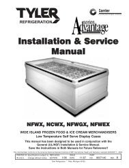
INSTALLATION & SERVICE MANUAL (ISM) A5FGN(T ... - Hillphoenix
INSTALLATION & SERVICE MANUAL (ISM) A5FGN(T ... - Hillphoenix
INSTALLATION & SERVICE MANUAL (ISM) A5FGN(T ... - Hillphoenix

You also want an ePaper? Increase the reach of your titles
YUMPU automatically turns print PDFs into web optimized ePapers that Google loves.
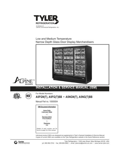
Low and Medium Temperature<br />
Narrow Depth Glass Door Display Merchandisers<br />
<strong>INSTALLATION</strong> & <strong>SERVICE</strong> <strong>MANUAL</strong> (<strong>ISM</strong>)<br />
For Model Numbers:<br />
<strong>A5FGN</strong>(T), A5FG(T)BB • A5NGN(T), A5NG(T)BB<br />
Manual Part no. 10000004<br />
<strong>ISM</strong> Document Information<br />
Issue Date<br />
February 2009<br />
~<br />
Revision Mark<br />
First Edition<br />
~<br />
Replaces<br />
n/a<br />
Details of each revision can be<br />
found on page 32 of this manual.<br />
Individual product <strong>ISM</strong>’s are designed as supplements to Tyler’s General Installation & Service Manual.<br />
Copies of current <strong>ISM</strong>’s are available on the Tyler Refrigeration website in the Quick Reference section.<br />
Tyler Refrigeration • 1329 Lake Street, Niles Michigan 49120 USA<br />
ph: 800.992.3744 • fax: 269-684-9802 • email: tylercorp@carrier.utc.com • www.carrier-tyler.com
<strong>A5FGN</strong>(T), A5FG(T)BB, A5NGN(T), A5NG(T)BB<br />
TABLE OF CONTENTS<br />
INTRODUCTION . . . . . . . . . . . . . . . . . . . . . . . . . . . . .3<br />
Delivery Inspection . . . . . . . . . . . . . . . . . . . . . . . . . .3<br />
Packaging . . . . . . . . . . . . . . . . . . . . . . . . . . . . . . . . .3<br />
Location . . . . . . . . . . . . . . . . . . . . . . . . . . . . . . . . . . .4<br />
<strong>INSTALLATION</strong><br />
Leveling . . . . . . . . . . . . . . . . . . . . . . . . . . . . . . . . . . .5<br />
Case Movement . . . . . . . . . . . . . . . . . . . . . . . . . . . . .8<br />
Drain Line . . . . . . . . . . . . . . . . . . . . . . . . . . . . . . . . .9<br />
Lineup Assembly . . . . . . . . . . . . . . . . . . . . . . . . . . .10<br />
Kickplate and Bumper . . . . . . . . . . . . . . . . . . . . . . .12<br />
Under-Case Return Airflow . . . . . . . . . . . . . . . . . . .13<br />
REFRIGERATION<br />
Refrigerant Piping . . . . . . . . . . . . . . . . . . . . . . . . . .14<br />
Temperature Control Adjustment . . . . . . . . . . . . . . .14<br />
Leak Check > Evacuation > Charging . . . . . . . . . . .15<br />
Line Sizing Tables . . . . . . . . . . . . . . . . . . . . . . . . . .16<br />
ELECTRICAL . . . . . . . . . . . . . . . . . . . . . . . . . . . . . . .19<br />
Optional Electrical Wiring . . . . . . . . . . . . . . . . . . . . .19<br />
Wiring Diagrams . . . . . . . . . . . . . . . . . . . . . . . . . . .20<br />
DEFROSTING<br />
Defrost Setting and Controls . . . . . . . . . . . . . . . . . .25<br />
Electric Defrost Operation . . . . . . . . . . . . . . . . . . . .26<br />
Gas Defrost Operation . . . . . . . . . . . . . . . . . . . . . . .26<br />
Limit Thermostat . . . . . . . . . . . . . . . . . . . . . . . . . . .26<br />
Coil Parts Breakdown . . . . . . . . . . . . . . . . . . . . . . .27<br />
USER INFORMATION AND <strong>SERVICE</strong><br />
User Information . . . . . . . . . . . . . . . . . . . . . . . . . .28<br />
Cleaning<br />
Shelf Location<br />
Shelves<br />
Loading the Case<br />
Light Switch<br />
Case Thermometer<br />
Case Lineup Combinations and Length Chart . . .29<br />
Service . . . . . . . . . . . . . . . . . . . . . . . . . . . . . . . . . .28<br />
Evaporator<br />
Expansion Valve<br />
Defrost Heater Element . . . . . . . . . . . . . . . . . . . .30<br />
Heater Element Removal<br />
Evaporator Fans<br />
Air-Curtain Velocity<br />
Fan Removal<br />
Ballasts<br />
Fluorescent Lighting<br />
Optional Lighting . . . . . . . . . . . . . . . . . . . . . . . . .31<br />
Front Edge Trim Replacement . . . . . . . . . . . . . . .31<br />
REVISION LOG . . . . . . . . . . . . . . . . . . . . . . . . . . . . .32<br />
EQUIPMENT WARRANTY . . . . . . . . . . . . . . . . . . . .33<br />
Tyler Refrigeration • Niles Michigan USA<br />
2<br />
February 2009
Manual Part #: 10000004<br />
INTRODUCTION<br />
Information contained in this manual pertains to both<br />
low-temperature and medium-temperature display<br />
merchandisers, including models:<br />
<strong>A5FGN</strong> <strong>A5FGN</strong>T A5FGBB A5FGTBB<br />
<strong>A5FGN</strong>E <strong>A5FGN</strong>TE A5NGNE A5NGNTE<br />
A5NGN A5NGNT A5NGBB A5NGTBB<br />
The use of the name “merchandiser” and “case” are<br />
used interchangeably and have the same meaning. Also,<br />
the term “freezer” refers to the A5F series of frozen glass<br />
door merchandisers, while the term “cooler” represents<br />
the A5N medium temperature versions.<br />
Tyler has made every effort to provide refrigeration<br />
equipment of the highest quality using state-of-the-art<br />
components. Merchandisers are built with the thickest<br />
insulation in the industry with a high-efficiency evaporator<br />
coil.<br />
Potential case features include:<br />
• Brushless D.C. electronic motors or PSC or<br />
shaded pole fan motors<br />
• T8 fluorescent lamps<br />
• LED lighting<br />
• Standard-energy, low-energy or no-energy doors<br />
These display cases were designed and tested using the<br />
following industry standards:<br />
• ASHRAE Standard 72-2005 – Method of Testing<br />
Commercial Refrigerators and Freezers (ANSI<br />
Approved)<br />
• ARI 1200- Performance Rating of Commercial<br />
Refrigerated Display Merchandisers and Storage<br />
Cabinets (ANSI Approved)<br />
• UL 471- Commercial Refrigerators and Freezers<br />
(ANSI Approved) (equipment certified by ETL)<br />
• NSF 7- Commercial Refrigerators and Freezers<br />
(ANSI Approved) (equipment certified by NSF)<br />
ASHRAE 72-2005 specifies the test conditions for the<br />
equipment. It includes the ambient conditions of 75° F<br />
dry bulb and 55% RH. It also specifies the door opening<br />
requirements for the performance test. Doors are<br />
opened six times in one hour for 6 seconds. The door<br />
opening test period is for 8 hours during one 24-hour<br />
performance test. As an example a 5-door case will<br />
have 240 door openings during one 24-hour test.<br />
Consult the factory if your store exceeds these test<br />
conditions.<br />
Delivery Inspection<br />
These display cases were carefully tested in the factory,<br />
inspected and properly packed to ensure delivery in the<br />
best possible condition. The equipment should be<br />
uncrated and checked for damage immediately upon<br />
delivery. DAMAGE MUST BE NOTED AT TIME OF<br />
DELIVERY AND ALL CLAIMS FOR DAMAGES MUST<br />
BE FILED WITH THE TRANSPORTATION COMPANY -<br />
NOT WITH TYLER. The carrier will supply necessary<br />
report and claim forms.<br />
Packaging<br />
Each case within a lineup is labeled to identify the lineup<br />
and joint. Labels use a number and letter designation<br />
(Figure 1). The number indicates the lineup. The letter<br />
indicates the case joint. Case joints begin with the letter<br />
A at the left most joint in the lineup, when looking at the<br />
front of the lineup. The joint for two cases has the same<br />
number-letter designation. Back-to-back cases have a<br />
unique designation. The leftmost joint in the lineup when<br />
looking at the front of the case is labeled 1-A. The joint<br />
on the back of the case is 1-A1.<br />
Insulated dividers are factory installed to separate low<br />
and medium temperature cases. They are also used to<br />
join different case models. Factory installed “Plexi” glass<br />
dividers separate refrigeration circuits.<br />
The first case in the lineup (with it’s right side labeled A)<br />
has a packet attached to the door handle that contains<br />
the manual, special instructions for installing ordered<br />
options, and touch up paint if the cases are custom<br />
painted. Every other case in the lineup has a packet<br />
attached to the door that contains the specific information<br />
for that case. The packing slip is taped to each<br />
case’s right hand door.<br />
Bumpers and kickplates are shipped on top of the case.<br />
Shelves for the case are tie wrapped and blocked into<br />
the individual cases. Other accessories like, drain traps,<br />
drain pans, condensate evaporating pans, and hat<br />
channels are shipped in the case that require the parts.<br />
Materials for joining cases include caulk, joining bolts,<br />
splices and T or J strips. These parts are supplied in<br />
cases that have a left-side insulated divider or no left<br />
end. The parts are bagged and taped to the coil covers.<br />
The T and J strips are tied to the shelves.<br />
February 2009<br />
3<br />
www.carrier-tyler.com
Introduction<br />
<strong>A5FGN</strong>(T), A5FG(T)BB, A5NGN(T), A5NG(T)BB<br />
Location<br />
These cases must not be installed in the direct rays of<br />
the sun or near a source of radiant heat.<br />
Be certain that the floor under the installation is of sufficient<br />
strength to prevent sagging. Out of level conditions<br />
will result in reduced performance.<br />
Wall merchandisers (those set with their backs to a wall)<br />
and merchandisers set back-to-back should be<br />
positioned to allow a minimum of 2" - 4" of space behind<br />
the back of the unit(s). This will allow necessary air to<br />
circulate behind the display case(s). Higher humidity<br />
stores with minimal air circulation require a 4" gap.<br />
Figure 1: Case label information<br />
Tyler Refrigeration • Niles Michigan USA<br />
4<br />
February 2009
Manual Part #: 10000004<br />
<strong>INSTALLATION</strong><br />
Leveling<br />
Merchandisers must be installed perfectly level to allow<br />
efficient operation of the refrigeration coils and complete<br />
drainage of defrost water. Since a level area is seldom<br />
available, the following steps are recommended to<br />
insure a level installation.<br />
1. Measure off and mark on floor the exact dimensions<br />
of the case lineup. (Check blueprints).<br />
2. Snap a chalk line at the locations for the front and<br />
back positions of the base rails (Figure 2-A).<br />
3. Mark locations of all joints (front and back).<br />
4. Using a laser or transit, find the highest point along<br />
both base rail position lines. Using the high point as<br />
a reference, mark the difference directly on the floor<br />
to each joint (front and back)(Figure 2-B).<br />
5. If you plan on using optional hat channels to raise<br />
the case height, place them under each pair of<br />
bases (Figure 3). Three and four door hat channels<br />
will be angled slightly to support the front and rear<br />
bases.<br />
6. Place the required number of shims under each<br />
base or optional hat channel at each joint (front and<br />
back) to equal the highest point.<br />
The <strong>A5FGN</strong>(T) and A5NGN(T) 2 through 5 door<br />
merchandisers have segmented bases mounted at<br />
the ends and under the center section of the case.<br />
Back-to-Back versions have full bases that run from<br />
front to back and are located at the ends and under<br />
the center sections of the case. The <strong>A5FGN</strong>(T)E<br />
and A5NGN(T)E crown-ends have segmented<br />
bases that run front-to-back.<br />
7. Tape all shims in place (Figure 2-C).<br />
8. Correctly orient the shims under the base or channel.<br />
Both corners of the base must be supported by shims<br />
to prevent the base from buckling (Figure 4).<br />
9. Place additional support shims under all other bases<br />
or hat channels (Figures 5A, 5B & 5C).<br />
10.If you’ve purchased seismic restraints, specific<br />
instructions for attaching those restraints are included<br />
in your document package. These instructions<br />
should be read and followed before the line up is<br />
assembled.<br />
Case Front<br />
Shim Placement<br />
Case Front<br />
Figure 2: Leveling cases prior to joining<br />
A<br />
B<br />
C<br />
Base<br />
Shim<br />
Base<br />
Shim<br />
February 2009<br />
5<br />
Hat section<br />
Figure 3: Typical hat channel locations<br />
www.carrier-tyler.com
Installation<br />
Figure 4: Shims under bases and case<br />
Figure 5A: Base Locations<br />
Tyler Refrigeration • Niles Michigan USA<br />
6<br />
February 2009
Manual Part #: 10000004<br />
Figure 5B: Base Locations for 2-5 door back-to-backs<br />
Figure 5C: Base Locations for end case<br />
February 2009<br />
7<br />
www.carrier-tyler.com
Installation<br />
<strong>A5FGN</strong>(T), A5FG(T)BB, A5NGN(T), A5NG(T)BB<br />
Case Movement<br />
The back-to-back (BB) cases are shipped with wood<br />
planks that allow the use of pipe rollers. These wood<br />
planks should be removed after the case is moved to its<br />
final location (Figure 6).<br />
All cases have steel protective support plates under the<br />
ends (not under insulated dividers). They are designed<br />
to protect the end from Johnson bar damage.<br />
Use the following methods to move the cases.<br />
Model<br />
* Fork-lift from the rear<br />
Fork lift Johnson Furniture<br />
from ends bar Dolly<br />
Pipe<br />
Rollers<br />
Safe (case)<br />
jacks<br />
A5F(N)GN(T) ̌ ̌ ̌ ̌<br />
A5F(N)G(T)BB ̌ ̌ ̌ ̌ ̌<br />
A5F(N)GN(T)E ̌* ̌ ̌<br />
Care should be taken when moving the cases. The<br />
doors should be secured so they cannot open while the<br />
case is moved.<br />
Only experienced certified fork truck drivers should use<br />
fork trucks to move the cases. The case should only be<br />
lifted off the floor as high as necessary for transport. The<br />
fork truck should be driven slowly avoiding any abrupt<br />
motions or bumps.<br />
The following fork-lift dimensions must be maintained to<br />
avoid damaging the case when it is lifted:<br />
2-Door Merchandisers<br />
Forks must extend from 26" to no more than 30"<br />
under the case.<br />
3-Door Merchandisers<br />
Use 48" long forks. Forks must extend from 39" to no<br />
more than 43" under the case.<br />
4 and 5 Door Merchandisers<br />
Use 48" long forks. Forks must extend from 44" to<br />
47" under the case.<br />
Fork blades wider than 4" will not fit into the bases.<br />
For low shipping height applications such as the use of<br />
the optional Remote Condenser Unit (RCU), Tyler has<br />
optional expandable bases. As shipped, the base is<br />
1-3/4" tall. It is attached with spacers that allow the base<br />
to slide away from the bottom of the case creating a gap<br />
that allows the use of a 1-1/2" thick fork-truck blade.<br />
Figure 6: Removing wood planks<br />
Tyler Refrigeration • Niles Michigan USA<br />
8<br />
February 2009
Manual Part #: 10000004<br />
Drain Line<br />
The drain is located at the center of the case in the floor<br />
pan. The drain can be reached by removing the center<br />
coil covers and then removing a fan motor. The 1" PVC<br />
drain outlet is located at the center-front of the case<br />
behind the kickplate.<br />
Install the tee to the outlet pipe and a drain trap to the<br />
tee. Plug the open end of the tee using the clean-out<br />
plug supplied with the drain trap kit. The drain line must<br />
be pitched away from the case. The tee, drain trap and<br />
plug are supplied with the case, and the factory installs a<br />
drain support at the front of the case. A trap support is<br />
supplied and is field mounted to the case (Figure 7).<br />
The drain trap must be level and should be primed with<br />
water after installation.<br />
Figure 7: Trap Support<br />
February 2009<br />
9<br />
www.carrier-tyler.com
Installation<br />
<strong>A5FGN</strong>(T), A5FG(T)BB, A5NGN(T), A5NG(T)BB<br />
Lineup Assembly<br />
1. Set the first case into the desired position and<br />
level it. Run a 1/4" to 3/8" diameter bead of Butyl<br />
caulk 1/2" in from both the inner and outer<br />
surfaces of the case end. (Figure 8).<br />
2. Push the second case against the end of the first.<br />
Level the second case. Remove the left and right<br />
end-coil covers and the rectangular pocket hole<br />
covers, accessing the holes in the end frames of<br />
each case as shown. The bolt kit supplied with<br />
the cases includes diagrams of these locations.<br />
Install tee-strips between the door frames at case<br />
joints (See Figure 9). Use the special screws<br />
and nuts provided.<br />
3. Start the joining bolts, but do not tighten them.<br />
Begin tightening the bolts at the top rear, working<br />
down the back of the case and up the front<br />
making sure that the front seams are flush.<br />
4. For NSF case installation, the interior case<br />
seams need to be sealed using NSF approved<br />
caulk (not supplied) (Figure 10).<br />
5. The end-panel protector support plates should<br />
be removed after the cases are set in their final<br />
position.<br />
Figure 9: T-Strips<br />
DO NOT APPLY EXCESS AMOUNTS OF BUTYL SEALANT THAT WOULD CAUSE IT TO SQUEEZE ONTO END<br />
FRAME METAL AREAS. Caulk-sealant used to join cases and complete the sealing requirements for NSF compliance<br />
should not come in contact with butyl sealant. Apply to clean, dry surfaces free of contaminants that adversely affect<br />
adhesion and could change color of sealant joint areas over time.<br />
B<br />
Procedure for Joining Cases<br />
A<br />
DETAIL A<br />
SCALE 1 : 5<br />
DETAIL B<br />
SCALE 1 : 5<br />
1/4" - 3/8" TYPICAL<br />
BUTYL SEALANT<br />
BEADS<br />
1/4" - 3/8" TYPICAL<br />
BUTYL SEALANT<br />
BEADS<br />
These procedures are critical! Failure to follow these<br />
guidelines will result in a poorly functioning case. This<br />
is especially true of freezers.<br />
1. Apply two 1/4" to 3/8" wide beads of Butyl sealant, 1/2" in<br />
from the inside and outside edges of the foamed insulated<br />
ceiling, rear wall, base, and door frame to be joined. Apply to<br />
only one case joint to avoid excessive amounts of Butyl<br />
sealant that would squeeze out of the joint. Sealant is not<br />
applied to the structural steel end frames. After cases are<br />
joined, caulk the top and back exterior seams (if possible) at<br />
this time.<br />
2. When joining ends of cases, caulk sealant should be<br />
applied in the same like manner for joints.<br />
If 4 shipping blocks are installed to inside of base<br />
ends, remove them to comply with NSF.<br />
Figure 8: Caulking cases to be joined<br />
Tyler Refrigeration • Niles Michigan USA<br />
10<br />
February 2009
Manual Part #: 10000004<br />
Figure 10: Required sealing for NSF approved installations<br />
February 2009<br />
11<br />
www.carrier-tyler.com
Installation<br />
<strong>A5FGN</strong>(T), A5FG(T)BB, A5NGN(T), A5NG(T)BB<br />
Kickplate and Bumper<br />
A custom Tyler cart bumper is standard on all case<br />
models and is installed at the bottom front of the case.<br />
The assembly is adjustable to compensate for uneven<br />
floors.<br />
Installing the End Kickplate (Figure 11A)<br />
The end kickplate attaches to small brackets that are<br />
affixed to each side of the case. The kickplate can be<br />
adjusted vertically to match the height of the floor below<br />
it.<br />
1. Attach a Tinnerman clip to the side kickplate support.<br />
2. Place the end kickplate against the Tinnerman clip on<br />
the end kickplate support.<br />
3. Install a black 3/4" screw through the end kickplate<br />
into the Tinnerman clip. A scratch-awl or similar tool<br />
can be used to line up the holes.<br />
4. The front lip of the end kickplate lies behind the front<br />
kickplate and is attached with screws to the front<br />
kickplate and front-end kickplate supports.<br />
Installing the Front Kickplate &Bumper<br />
(Figures 11A & B)<br />
The front kickplate and bumper attaches using 1½"<br />
screws attached to support brackets located on the front<br />
of the case. The kickplate can be adjusted up and down<br />
to fit the height of the floor below it.<br />
1. Starting from the left end of the lineup, attach a<br />
Tinnerman clip to each kickplate support. Locate<br />
them over the slot in the kickplate support.<br />
2. Attach a kickplate splice to the right side of the front<br />
kickplate using the ¾" screw in the lower hole.<br />
3. Lean the kickplate against the kickplate support.<br />
4. Place the bumper assembly on the case by hanging<br />
the bumper support onto the bumper hanger. The<br />
kickplate should be located behind the bumper<br />
support.<br />
5. Install the black 1½" screw through the bumper, front<br />
kickplate, kickplate splice, and into the Tinnerman<br />
clip. A scratch-awl or similar tool can be used to line<br />
up the holes.<br />
6. Follow these steps to install the next bumper in the<br />
Figure 11A: Installing the bumper and kickplate<br />
Tyler Refrigeration • Niles Michigan USA<br />
12<br />
February 2009
Manual Part #: 10000004<br />
lineup. A bumper support splice (provided) should be<br />
installed between the two cases. Center the splice<br />
over the gap using self-tapping screws (provided).<br />
Attach the upper portion of the splice using the<br />
predrilled holes in the splice. Then with two more<br />
screws, attach the lower half.<br />
Figure 11B: Bumper and Kickplate Configuration<br />
Under-Case Return Airflow<br />
To assemble the bumper for under case return airflow, a<br />
spacer (provided) must be inserted between the bumper<br />
support and kickplate (Figure 12). The spacer is held in<br />
place with the standard black assembly screw used to<br />
attach the bumper. One 3/8" spacer is required at each<br />
screw location (2 spacers on a 2-door, 3 spacers on a 3-<br />
door, etc.).<br />
1. To ease installation, hook the bumper to the case and<br />
position the kickplate. Then pull the bottom edge of<br />
the bumper forward, hold the spacer in place, and<br />
then insert the assembly screw through the bumper,<br />
spacer, kickplate, bumper bracket and into the<br />
Tinnerman clip.<br />
2. With the spacers in place, air will be allowed to flow<br />
between the bumper and kickplate and then underneath<br />
the case. The target airflow rate under the case<br />
should be 50 cfm/door.<br />
February 2009<br />
13<br />
Figure 12: Bumper / Under-case air flow<br />
www.carrier-tyler.com
<strong>A5FGN</strong>(T), A5FG(T)BB, A5NGN(T), A5NG(T)BB<br />
REFRIGERATION<br />
General<br />
Unless otherwise specified, the liquid and suction<br />
connections are made inside the case under the evaporator<br />
fan/coil cover. Refrigerant piping may enter the<br />
case through the front left bottom, the left rear bottom of<br />
case or the left rear top of case. The copper pipe should<br />
not touch or rub on the edges of the sheet metal. After<br />
connections have been made, the refrigeration access<br />
hole in the case must be sealed completely with<br />
aerosol¬ dispensed Urethane insulation or equivalent<br />
(i.e.: Great Stuff). Penetrations made in sheet metal<br />
baffles should also be sealed (Figure 13).<br />
Refrigerant Piping<br />
Correct refrigeration line sizing and installation is essential<br />
for proper system operation (see wiring diagrams on<br />
pages 16-18). A P-trap must be installed at the bottom<br />
of all vertical suction risers (Figure 14). Various risers<br />
are available as a factory installed option.<br />
When two or more case sections are connected to one<br />
compressor, the main liquid and suction line for the<br />
group should be run through the cases and be brought<br />
out through the refrigeration outlet of one case only. The<br />
factory recommends one riser per circuit/system for hot<br />
gas defrost when using top back refrigeration exit. Circuit<br />
risers are available as a factory installed option. Insulate<br />
the tubing for at least 20 feet from the case outlet. On<br />
30" wide door cases with suction lines over 1-3/8"<br />
diameter, a P-trap made with 45° elbows is required<br />
(Figure 14). A piping chase in front of the fan shroud<br />
allows the refrigerant lines to be run through the right or<br />
left end frame.<br />
Piping should not be placed near the electric defrost<br />
heaters. The defrost heaters on the 30" door cases will<br />
grow one inch to the left of the coil when they reach<br />
operating temperature.<br />
The compressor should be installed as close as possible<br />
to the cases to reduce pressure drop. Install a shallow<br />
trap at the bottom of the riser.<br />
The suction and liquid lines may be taped together to<br />
form an external heat exchanger.<br />
The best location for the liquid line drier is inside the<br />
freezing compartment. However, it may be installed near<br />
the compressor for easy maintenance. Install moisture<br />
indicating sight glass at the outlet end of the drier.<br />
A low pressure or temperature control can be used to<br />
control case temperature. The control should be<br />
Figure 13: Penetration sealing<br />
selected with adequate contact capacity for the switching<br />
load. In rack systems, an evaporator pressure-regulating<br />
valve may be used to control the evaporating temperature.<br />
The settings (See Figure 16) are approximate due to<br />
variations in gauge accuracy, differences in compressor<br />
efficiency, line pressure drop, and super heat settings.<br />
Before making adjustments for store or stocking conditions,<br />
make sure the super heat is set between 6°F and<br />
10°F. Close coupled systems typically run at the higher<br />
end of this range to avoid flood back.<br />
Temperature Control Adjustment<br />
When factory installed, the temperature control is<br />
located toward the right end of the case behind the black<br />
kick plate. The sensing bulb is located under the coil<br />
cover on the back side of the fan shroud. It can be wired<br />
in series with the low pressure (L.P.) control. It can also<br />
be used in a pump-down system by wiring it in series<br />
with the liquid solenoid valve. A thermostat is shown in<br />
Figure 15.<br />
Discharge-air temperature probes for electronic case<br />
controllers may be installed in many different customer<br />
specified locations including, but not limited to, honeycomb,<br />
ceiling pocket cover, rear wall, and return air.<br />
Tyler Refrigeration • Niles Michigan USA<br />
14<br />
February 2009
Manual Part #: 10000004<br />
Leak Check > Evacuation > Charging<br />
After all of the refrigeration piping and system components have been assembled, the entire system must be pressurized<br />
and checked for leaks.<br />
When the system is leak free, evacuate with a deep vacuum pump. Triple evacuation to a minimum of 500 microns<br />
and nitrogen sweep is recommended. After the system has been thoroughly evacuated of all moisture and noncondensable<br />
gas, charge the system with the proper refrigerant, using “hi-side/low-side” charging techniques.<br />
Figure 14: 45 degree elbow suction line<br />
Figure 15: Temperature control<br />
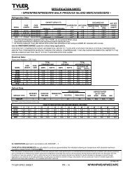
Figure 16: Temperature Settings for R404a Refrigerant<br />
Application<br />
Evaporator<br />
Temp (°F)<br />
Condensing Unit Discharge Air Temperature Return Air Temperature<br />
Cut-in Cut-out Cut-in Cut-out Cut-in Cut-out<br />
(psig) (psig) (°F) (°F) (°F) (°F)<br />
Frozen Food -7 35 24 +3 -3 +6 0<br />
Ice Cream -16 27 16 -3 -12 -3 -9<br />
Medium Temp. +28<br />
Note: These set points may require optimization for your applications to prevent short-cycling or delayed cycling.<br />
February 2009<br />
15<br />
www.carrier-tyler.com
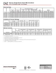
Refrigeration<br />
<strong>A5FGN</strong>(T), A5FG(T)BB, A5NGN(T), A5NG(T)BB<br />
R-404a Line Sizing Tables for Tyler A5 Frozen Foods Merchandisers (-7° Evap. Temp.)<br />
Tyler Refrigeration • Niles Michigan USA<br />
16<br />
February 2009
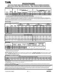
R-404a Line Sizing Tables for Tyler A5 Ice Cream Merchandisers (-16° Evap. Temp.)<br />
Manual Part #: 10000004<br />
February 2009<br />
17<br />
www.carrier-tyler.com
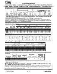
Refrigeration<br />
<strong>A5FGN</strong>(T), A5FG(T)BB, A5NGN(T), A5NG(T)BB<br />
R-404a Line Sizing Tables for Tyler A5 Medium Temp. Merchandisers (+28° Evap. Temp.)<br />
Tyler Refrigeration • Niles Michigan USA<br />
18<br />
February 2009
Manual Part #: 10000004<br />
ELECTRICAL<br />
CAUTION !<br />
DISCONNECT POWER TO THE CASE<br />
BEFORE SERVICING ELECTRICAL COMPONENTS<br />
TO AVOID PERSONAL INJURY AND DAMAGE TO<br />
THE UNIT.<br />
Figure 17 shows the typical wiring diagram for a freezer<br />
equipped with electric defrost, Figure 18 shows the<br />
typical wiring diagram for a freezer equipped with hot<br />
gas defrost, and Figure 19 shows a medium-temperature<br />
cooler with time-off defrosting. Each case ships with a<br />
wiring diagram located in the electric box that shows the<br />
exact wiring of the case.<br />
There are many control options available for multiple<br />
case defrost systems. Wiring diagrams and instructions<br />
can be obtained by contacting the Tyler Refrigeration<br />
Service Department.<br />
External wiring should be sized according to the<br />
amperage rating stamped on the serial plate. The serial<br />
plate is located on the ceiling inside the left-hand door.<br />
Typical electrical values are shown on specification<br />
sheets for each of these cases in the bag attached to the<br />
case or are available at the Tyler Refrigeration website<br />
(www.carrier-tyler.com). All internal wiring has been<br />
completed at the factory. Cases with standard wiring<br />
have their control wires terminated in the electrical<br />
compartment located behind the kickplate at the right<br />
end of the case. A terminal block has been used to<br />
simplify field connections. An electrical box is mounted<br />
on the top of the unit for cases equipped with the<br />
optional top mount electrical connections.<br />
All wiring must comply with the National Electrical Code<br />
and all local codes. After installation of the equipment,<br />
correct operation of the electrical circuits and controls<br />
and defrost operation and termination should be verified.<br />
All operating voltages and amperages should be<br />
measured and recorded.<br />
Optional Electrical Wiring<br />
Master-Satellite Connection<br />
The “master-satellite” connection system allows one<br />
condensing unit to be connected to multiple cases.<br />
Figures 20 and 21 shows typical diagrams for this<br />
system.<br />
All of the display case controls including the disconnect<br />
switch, time clock, temperature control, and defrost<br />
temperature control are installed behind the kick plate<br />
and pre-wired. The liquid line solenoid is pre-wired but<br />
is not installed in the liquid line.<br />
The power to operate each display case is connected at<br />
each cases’ disconnect switch. The power to operate<br />
the condensing unit is connected at the condensing unit.<br />
There are no interconnecting wires between the<br />
condensing unit and display case. There are interconnecting<br />
wires that need to be connected between the<br />
cases. The liquid line solenoid valve needs to be<br />
installed in the common liquid line before the liquid is<br />
distributed to the cases.<br />
The controls operate the system as a pump down<br />
defrost. When the display case begins defrost, the liquid<br />
line solenoid valve, fans and anti-sweat heaters are deenergized.<br />
The defrost heaters are energized. The<br />
compressor continues to run and pumps down the coil.<br />
The master case contains the time clock. Interconnecting<br />
case wiring allows the master case to control the<br />
satellite cases. When defrost is initiated in the master<br />
case, it sends an electrical signal to each satellite case<br />
to energize the defrost relay and initiate a defrost in all of<br />
the cases. A second set of interconnecting wires are<br />
connected in series between each of the cases. Each<br />
case defrost heater is de-energized when the coil<br />
reaches the defrost termination temperature. An<br />
additional signal is relayed to the next case indicating<br />
that the termination temperature has been reached.<br />
When all of the cases have reached termination temperature,<br />
the defrost termination circuit is complete and the<br />
defrost is terminated.<br />
The liquid line solenoid is energized at the end of the<br />
defrost cycle and the defrost heaters are de-energized.<br />
The suction line pressure rises and the compressor<br />
starts. When the evaporator reaches operating temperature,<br />
the delay thermostat (klixons) will close, energizing<br />
the fans and anti-sweat door heaters.<br />
February 2009<br />
19<br />
www.carrier-tyler.com
Wiring Diagram<br />
Figure 17: Electric Defrost <strong>A5FGN</strong>(T), A5FG(T)BB<br />
Tyler Refrigeration • Niles Michigan USA<br />
20<br />
February 2009
Wiring Diagram<br />
Figure 18: Hot Gas Defrost <strong>A5FGN</strong>(T), A5FG(T)BB<br />
Manual Part #: 10000004<br />
February 2009<br />
21<br />
www.carrier-tyler.com
Wiring Diagram<br />
Figure 19: Time-off Defrost A5NGN(T), A5NG(T)BB<br />
This wiring diagram for A5NGN(T)<br />
cooler merchandisers is applicable to<br />
both master and satellite cases. The<br />
diagram shows a Defrost Time Clock,<br />
Temperature Control, and Solenoid<br />
Valve. These are required only on the<br />
master case. The satellite case would<br />
only require terminal blocks for lights,<br />
fans, and anti-sweats. Field-install<br />
from the master to the satellite wires<br />
to the respective terminal blocks.<br />
Tyler Refrigeration • Niles Michigan USA<br />
22<br />
February 2009
Master / Satellite Wiring Diagrams (low-temp)<br />
Figure 20: Master (Controller)<br />
<strong>A5FGN</strong>(T), A5FG(T)BB<br />
February 2009<br />
23<br />
www.carrier-tyler.com
Master / Satellite Wiring Diagrams (low-temp)<br />
Figure 21: Satellite (Controlled)<br />
Tyler Refrigeration • Niles Michigan USA<br />
24<br />
February 2009
Manual Part #: 10000004<br />
DEFROSTING<br />
General<br />
Periodic defrosting to keep the coil free of frost is accomplished<br />
automatically by a time clock only in mediumtemperature<br />
coolers, or used in conjunction with an<br />
electric or hot gas defrost in low-temperature freezers.<br />
Defrost Settings and Controls<br />
Off-Cycle Defrost<br />
Medium temperature coolers are typically defrosted by<br />
using an “off-cycle defrost”. During an off-cycle defrost,<br />
refrigeration to the cases is halted, but the evaporator<br />
fans continue to run. Frost is melted by the warmth of<br />
the display case’s internal air. Typically, anti-sweat<br />
heaters and display lights operate during defrost. Defrost<br />
may be terminated by time (30 minutes) or upon<br />
reaching a coil temperature of 43°F.<br />
Electric Defrost<br />
Frequency: One electric defrost per day is recommended.<br />
Time of day: Nighttime defrosting is preferred to avoid<br />
periods of shopping or stocking.<br />
Duration: Electric defrost does not require any drip time<br />
because Tyler provides a built-in fan delay thermostat.<br />
Electric defrost for low-temp and off-cycle for mediumtemp<br />
Fail-safe Times:<br />
Ice Cream Frozen Food Med. Temp<br />
<strong>A5FGN</strong>(BB) 1/day at 45 mins 1/day at 45 mins<br />
<strong>A5FGN</strong>T(BB) 1/day at 55 mins 1/day at 55 mins<br />
A5NGNT(BB)<br />
3/day at 30 mins<br />
At ASHRAE test conditions and 208 volt defrost heater<br />
operation, the typical observed <strong>A5FGN</strong> 30" door defrost<br />
durations are 28 minutes for ice cream and 19 minutes<br />
for frozen food. At the same conditions, the typical<br />
observed <strong>A5FGN</strong>T 30" door defrost durations are 39<br />
minutes for ice cream and 26 minutes for frozen food.<br />
<strong>A5FGN</strong>(T)E Crown End defrost durations are 43<br />
minutes.<br />
Preferred Termination: For optimal performance,<br />
Tyler recommends a temperature-terminated defrost,<br />
using a defrost termination thermostat or probe<br />
sensing the coil temperature.<br />
<strong>A5FGN</strong> and <strong>A5FGN</strong>T door case has the probe located at<br />
the right hand side of the coil in the center of the bottom<br />
row of tubes.<br />
The <strong>A5FGN</strong>E and <strong>A5FGN</strong>TE case has the probe located<br />
at the right hand side of the coil in the top row of tubes.<br />
Tyler provides a defrost termination thermostat as<br />
standard unless a control system defrost probe is<br />
requested. The defrost termination temperature is 50°F.<br />
Temperature termination based on coil temperature<br />
allows the length of defrost to vary depending on how<br />
much frost is on the coil and the defrost heater voltage.<br />
Coil frost is a function of shopping patterns, stocking<br />
habits, general door maintenance and ambient temperature<br />
and humidity. More frost requires a longer defrost. A<br />
lower defrost heater voltage extends the defrost period.<br />
Alternate Termination: If it is not possible to terminate the<br />
defrost cycle based on a defrost termination thermostat<br />
or probe sensing the temperature at the coil, and the<br />
only available temperature probe is sensing the<br />
discharge air temperature, then the termination temperature<br />
should be set to 65°F, zero minutes drip time.<br />
Tyler electric defrost freezers are delivered with the<br />
defrost thermostat open-on-rise contacts wired-in series<br />
with the defrost heaters. Unless the installer rewires the<br />
defrost thermostat, the defrost heater is de-energized<br />
when defrosting is complete.<br />
Tyler electric defrost freezers are also equipped with a<br />
high-limit, snap-disc thermostat that de-energizes the<br />
defrost heater if the coil temperature exceeds 80°F to<br />
provide a secondary safety termination.<br />
Hot Gas Defrost<br />
Frequency: One hot gas defrost per day is recommended.<br />
Time of day: Nighttime defrosting is preferred to avoid<br />
periods of shopping or stocking.<br />
Duration: Hot gas defrost requires a 5 minute drip time.<br />
February 2009<br />
25<br />
www.carrier-tyler.com
Defrosting<br />
<strong>A5FGN</strong>(T), A5FG(T)BB, A5NGN(T), A5NG(T)BB<br />
Hot Gas Defrost Fail-safe Times:<br />
Hot Gas<br />
Reduced<br />
Temperature<br />
Gas<br />
Preferred Termination: For optimal performance,<br />
Tyler recommends a temperature-terminated defrost,<br />
using a defrost termination thermostat or probe<br />
attached to the dump line.<br />
At ASHRAE test conditions, termination ranges from 12-<br />
22 minutes.<br />
Defrost termination thermostats are optional on hot gas<br />
or reduced-temperature gas applications. If the cases<br />
are so equipped, the defrost termination is 65°F.<br />
Electric Defrost Operation<br />
The compressor stops when the defrost is initiated in a<br />
non-pump-down system. On pump-down systems, the<br />
liquid line solenoid will be de-energized when the defrost<br />
is initiated. The clock will energize the 208/230 volt<br />
defrost heater, and energize the normally closed<br />
208/230 volt contactor or relay. This de-energizes the<br />
115-volt fans, lights and anti-sweat heaters. If you don’t<br />
have a light circuit limit thermostat, the lights will not deenergize.<br />
After the defrost period, the compressor will operate.<br />
When the coil temperature reaches +5°F, the fan, light<br />
and anti-sweat heater limit thermostats (Klixons) will<br />
close, starting the fans, lights and anti-sweat heaters<br />
(Figure 22).<br />
Gas Defrost Operation<br />
Ice Cream<br />
1/day at 30 mins<br />
5 min. drip<br />
1/day at 40 mins<br />
5 min. drip<br />
Frozen Food<br />
1/day at 30 mins<br />
5 min. drip<br />
1/day at 40 mins<br />
5 min. drip<br />
Several types of gas defrost methods in conjunction with<br />
time actuated, time or temperature terminated defrost<br />
timers can be used to defrost the evaporator.<br />
The refrigeration system designer and installer are<br />
responsible for correct line sizing for effective gas<br />
defrost and liquid return from the freezers. Sizing and<br />
component selection depend on the type of defrost, size,<br />
and location of high side refrigeration system.<br />
Tyler freezers equipped for gas defrost consist of a side<br />
port distributor and a TXV check valve for coil defrost,<br />
and a suction line check valve to bypass hot gas to the<br />
serpentine coil. The serpentine coil is attached to the<br />
bottom of the pan to ensure pan and drain defrost.<br />
The timer starts the gas defrost cycle by energizing a<br />
solenoid, reversing valve, or directional valve. The gas is<br />
injected from the source into the suction line of the<br />
evaporator to be defrosted. The gas flows into the<br />
serpentine coil attached to the floor of the case and then<br />
into the evaporator. Condensed liquid leaves the evaporator<br />
through the side port distributor, through a check<br />
valve into the liquid line. (Figure 23).<br />
General Notes<br />
• The refrigeration technician should recheck coil<br />
condition after one week of retail operations to be<br />
certain that the frequency and duration of defrost<br />
is adequate for the particular store and locality.<br />
For example, if defrost voltage is below 200 volts,<br />
additional fail-safe time may be required.<br />
• When using time terminated defrost, defrost termination<br />
thermostat should be wired in series with<br />
the defrost heater.<br />
• Defrost termination thermostats may be wired in<br />
series for multiple evaporator installations.<br />
• Defrost termination thermostats may be used as a<br />
digital input for electronic controllers.<br />
Limit Thermostat<br />
Each freezer has factory set limit thermostats (Klixons)<br />
attached to the return bends of the coil on the right end<br />
of the freezer to regulate the operation of the evaporator<br />
fans and anti-sweat door heaters. A limit thermostat is<br />
optional for the light circuit. When a limit thermostat is<br />
provided in the lighting circuit, the lights will be off during<br />
defrost.<br />
IMPORTANT! OPERATION OF THE LIMIT THERMO-<br />
STATS CAUSES THE EVAPORATOR FANS, FREEZER<br />
LIGHTS, AND ANTI-SWEAT DOOR HEATERS TO<br />
REMAIN OFF UNTIL THE COMPRESSOR IS<br />
OPERATING AND THE COIL TEMPERATURE IS<br />
BROUGHT BELOW THE THERMOSTAT CUT-IN<br />
SETTING (+5°F ). SUPERHEAT MUST BE SET<br />
CORRECTLY BY THE INSTALLING CONTRACTOR<br />
FOR PROPER THERMOSTAT OPERATION.<br />
When the freezer first operates, the fans and lights may<br />
cycle off and on a few times until coil temperature is<br />
below +5°F. The superheat must be set for proper<br />
operation.<br />
The 30" door models have a high limit thermostat<br />
installed on the coil return bend, wired in series with the<br />
defrost heaters. This thermostat opens when the temperature<br />
reaches 80°F.<br />
Tyler Refrigeration • Niles Michigan USA<br />
26<br />
February 2009
Manual Part #: 10000004<br />
ITEM NO.<br />
PART NAME<br />
1 COIL COVER<br />
2 FAN<br />
3 LIQUID LINE<br />
4 SUCTION LINE<br />
5 FAN HOUSING<br />
6 HEAT EXCHANGER<br />
7 EXPANSION VALVE<br />
8 FRONT HEATING ELEMENT<br />
9 REAR HEATING ELEMENT<br />
10 HEATER CLIP<br />
11<br />
DEFROST TERMINATION<br />
PROBE LOCATION<br />
Figure 22: Coil Parts Breakdown, Electric Defrost<br />
ITEM NO. PART NAME<br />
1 COIL COVER<br />
2 FAN<br />
3 FAN HOUSING<br />
4 COIL<br />
5 CHECK VALVE<br />
6 SERPENTINE<br />
7 SLHX HEAT EXCHANGER<br />
8 TXV VALVE<br />
9 HAND VALVE (OPTIONAL)<br />
10 DRIER (OPTIONAL)<br />
11 CHECK VALVE<br />
12 SIGHT GLASS (OPTIONAL)<br />
13<br />
DEFROST TERMINATION<br />
PROBE LOCATION<br />
Figure 23: Coil Parts Breakdown, Hot Gas Defrost<br />
February 2009<br />
27<br />
www.carrier-tyler.com
<strong>A5FGN</strong>(T), A5FG(T)BB, A5NGN(T), A5NG(T)BB<br />
USER INFORMATION & <strong>SERVICE</strong><br />
User Information<br />
Cleaning<br />
Cases should be thoroughly cleaned before start-up and<br />
routinely thereafter to maintain a clean appearance. Use<br />
mild detergent and warm water (never an abrasive<br />
cleaner) to wipe out the inside of the case. Wash down<br />
all glass doors with glass cleaner. Do not use any<br />
products containing silicon on anti-fog glass coatings.<br />
Clean interior glass reduces fogging and increases<br />
visibility. The case will remain bright and sparkling with<br />
just a few minutes of cleaning each week. Internal<br />
components can be cleaned after removal of access<br />
panels. The case drain should be regularly cleared of<br />
debris and price tags.<br />
Do not use high-pressure water or steam to clean the<br />
interior.<br />
Shelf Location<br />
The shelves are adjustable in 1" increments and may be<br />
located in any position for the best display advantage.<br />
Be sure shelf clips or brackets are completely seated<br />
before installing the shelf. The shelf brackets (for wire<br />
shelves only) are stamped with “R” for Right and “L” for<br />
left for proper orientation when installing shelves.<br />
Shelves<br />
Tyler manufactures many different styles of shelves,<br />
baskets and product stops. The shelves and baskets are<br />
placed on the shelf brackets. Some of the baskets may<br />
be reversed and used as a typical shelf.<br />
Loading the Case<br />
The case may be loaded with merchandise after it has<br />
been operated for at least 24 hours with correct case<br />
temperature and proper control operation. While loading<br />
the shelves, leave an air space between the top of the<br />
merchandise and the shelf above it so the customer can<br />
remove the merchandise. The air space allows an air<br />
curtain on top of the product. Product should not extend<br />
beyond the front of the shelves or block the return air<br />
grill.<br />
The typical Cantilever shelf load is 170 lbs. with a<br />
maximum load of 235 lbs. Note some deflection may<br />
occur under higher loads.<br />
Light Switch<br />
A light switch is located inside the right-hand door. Turn<br />
the light switch off during the initial case temperature pull<br />
down to prevent the case lights from cycling off and on.<br />
Always turn the light switch off when replacing lamps.<br />
Case Thermometer<br />
Cases are typically shipped with 2 thermometers. One<br />
thermometer is factory mounted in the discharge air<br />
stream. The second thermometer is shipped loose and<br />
should be installed in the warmest product location.<br />
Specific instructions are packaged with the shipped<br />
loose thermometer.<br />
Service<br />
Cart bumpers must be removed to gain access to drain<br />
clean-outs and electrical connections. Disassemble the<br />
bumper and kickplate by removing the 2 or 3 metal<br />
screws located in the kickplate. The bumper assembly<br />
can be lifted up and removed from the case. The<br />
kickplate can be removed, exposing the electric tray<br />
cover and drain (Figure 11A).<br />
Evaporator<br />
The evaporator coil, located at the bottom-rear of the<br />
case is factory assembled with the distributor, expansion<br />
valve, and other refrigeration components. To inspect the<br />
coil, remove the center or left-of-center coil cover. A<br />
small inspection port is located at the rear of the case.<br />
To inspect the entire coil, remove the remaining coil<br />
covers and raise the evaporator cover.<br />
Expansion Valve<br />
A superheat-adjustable externally equalized thermostatic<br />
expansion valve, with a removable strainer and pressure<br />
limiting charge, is mounted to the evaporator coil -<br />
unless otherwise specified. The valve is not preset.<br />
Adjust the superheat setting for maximum coil effectiveness.<br />
Typical superheat settings are between 6°F and<br />
10°F. Close coupled systems should use the higher<br />
superheat setting to minimize the chance of liquid flood<br />
back.<br />
To adjust the expansion valve, remove the right end coil<br />
cover. Remove the cap from the bottom of the valve.<br />
When looking at the valve stem end, turn the valve stem<br />
counterclockwise to decrease superheat. Turn the valve<br />
stem clockwise to increase superheat. Measure the<br />
suction line temperature at the expansion valve-sensing<br />
bulb and compare it to the suction temperature corresponding<br />
to the saturated pressure. Make sure that line<br />
pressure drop is taken into account. (con’t on p.30)<br />
Tyler Refrigeration • Niles Michigan USA<br />
28<br />
February 2009
Manual Part #: 10000004<br />
Case Lineup Combinations and Length Chart<br />
Doors in<br />
Lineup<br />
2 Door<br />
Case<br />
3 Door<br />
Case<br />
4 Door<br />
Case<br />
5 Door<br />
Case<br />
Total length<br />
w/o ends (in.)<br />
Total length<br />
w/o ends (ft. & in.)<br />
2 1 62.13 5 ft 2-1/8 in<br />
3 1 92.50 7 ft 8-1/2 in<br />
4 1 123.00 10 ft 3 in<br />
5 1 153.38 12 ft 9-3/8 in<br />
6 2 185.00 15 ft 5 in<br />
7 1 1 215.50 17 ft 11-1/2 in<br />
8 2 246.00 20 ft 6 in<br />
9 1 1 276.38 23 ft 3/8 in<br />
10 2 306.75 25 ft 6-3/4 in<br />
11 1 2 338.50 28 ft 2-1/2 in<br />
12 3 369.00 30 ft 9 in<br />
13 2 1 399.38 33 ft 3-3/8 in<br />
14 1 2 429.75 35 ft 9-3/4 in<br />
15 3 460.13 38 ft 4-1/8 in<br />
16 4 492.00 41 ft<br />
17 3 1 522.38 43 ft 6-3/8 in<br />
18 2 2 552.75 46 ft 3/4 in<br />
19 1 3 583.13 48 ft 7-1/8 in<br />
20 4 613.50 51 ft 1-1/2 in<br />
21 4 1 645.38 23 ft 9-3/8 in<br />
22 3 2 675.75 56 ft 3-3/4 in<br />
23 2 3 706.13 58 ft 10-1/8 in<br />
24 1 4 736.50 61 ft 4-1/2 in<br />
25 5 766.88 63 ft 10-7/8 in<br />
26 4 2 798.75 66 ft 6-3/4 in<br />
27 3 3 829.13 69 ft 1-1/8 in<br />
28 2 4 859.50 71 ft 7-1/2 in<br />
29 1 5 889.88 74 ft 1-7/8 in<br />
30 6 920.25 76 ft 8-1/4 in<br />
31 4 3 952.13 79 ft 4-1/8 in<br />
32 3 4 982.50 81 ft 10-1/2 in<br />
33 2 5 1,012.88 84 ft 4-7/8 in<br />
34 1 6 1,043.25 86 ft 11-1/4 in<br />
35 7 1,073.63 89 ft 5-5/8 in<br />
36 4 4 1,105.50 92 ft 1-1/2 in<br />
37 3 5 1,135.88 94 ft 7-7/8 in<br />
38 2 6 1,166.25 97 ft 2-1/4 in<br />
39 1 7 1,196.63 99 ft 8-5/8 in<br />
40 8 1,227.00 102 ft 3 in<br />
February 2009<br />
29<br />
www.carrier-tyler.com
User Information & Service<br />
<strong>A5FGN</strong>(T), A5FG(T)BB, A5NGN(T), A5NG(T)BB<br />
Turn the valve stem only 1/4 turn at a time and allow<br />
sufficient time (20 to 30 minutes) for the valve to settle<br />
before making any further adjustments. Replace the<br />
valve stem cap after the valve super-heat has been<br />
adjusted. BE CERTAIN THE VALVE STEM CAP IS<br />
WIPED DRY FIRST.<br />
! CAUTION !<br />
DISCONNECT POWER TO THE CASE BEFORE<br />
SERVICING ELECTRICAL COMPONENTS TO AVOID<br />
PERSONAL INJURY AND DAMAGE TO THE UNIT.<br />
Defrost Heater Element<br />
On 30" door cases one heater is located on the front of<br />
the coil and one on the rear of the coil. On wraparound<br />
cases, the heater element is located under the coil. The<br />
electric wire leads are connected in the junction box<br />
behind the front kick rail.<br />
Heater Element Removal<br />
Defrost heaters for the electric defrost cases are located<br />
on the front and rear face of the coil. The front heater is<br />
located approximately 1” off the floor and the rear heater<br />
is approximately 2” off the floor. The heater is secured to<br />
the coil by a number of stainless steel heater retaining<br />
clips. Heaters are fastened to the floor on the right hand<br />
side of the coil. Remove fasteners holding the heater to<br />
the floor.<br />
The front heater can be removed by pulling the retaining<br />
clip away from the coil and sliding the heater out from<br />
under the clip.<br />
The rear heater can be removed by raising the heater<br />
retaining clip. Raise each clip about 2 inches above the<br />
coil working from right to left on the coil. Repeat this<br />
process until the retaining clips are free of the coil. The<br />
heater will slide up with the retaining clip.<br />
To remove the defrost element for the <strong>A5FGN</strong>(T)E<br />
Crown End, remove the coil covers. Lift the inner coil<br />
cover upward and tip the fan housing forward. This will<br />
expose the coil. Remove both fan housing end brackets<br />
and center coil supports, then slide out the complete<br />
heater pan assembly from under the coil. Slowly lift the<br />
heater pan assembly between the coil and fan housing,<br />
turning it on edge while lifting. Heaters are installed in<br />
the reverse order of how they were removed.<br />
Evaporator Fans<br />
Air is circulated throughout the case with 115-volt low<br />
temperature fan motors. These motors must be<br />
operating at all times except during defrosting (lowtemperature<br />
only). Fan motors should be replaced with<br />
motors having the same characteristics including type,<br />
physical size, wattage and RPM.<br />
Air-Curtain Velocities<br />
Air-curtain velocity for freezers and coolers are affected<br />
by stocking levels, coil frost loads, temperature and fan<br />
condition. The measurement method also affects the<br />
reading. Tyler recommends using an Alnor Velometer<br />
Jr., set to the 0-to-800 fpm range. Air velocity should be<br />
measured at the back edge of the discharge air honeycomb,<br />
at the center of the middle door in the case (other<br />
doors have slightly lower velocity). A typical velocity<br />
reading is 425 feet per minute (FPM) in a fully-packed<br />
freezer (395 FPM for medium-temperature coolers), after<br />
the freezer/cooler has defrosted and is pulled down to<br />
operating temperature. A typical velocity reading for tall<br />
cases is 400 FPM for freezers, and 370 FPM for coolers<br />
under the same conditions. Air-curtain velocity in a<br />
partially packed freezer is significantly lower because<br />
more air exits the back wall duct holes.<br />
Fan Removal<br />
1. Turn off power to fans. Remove coil cover.<br />
2. Unplug fan from fan power supply plug located on the<br />
front face of the fan housing.<br />
3. Remove the fan blade nut and fan blade.<br />
4. Remove the two mounting bolts and remove the fan<br />
assembly from the fan housing.<br />
5. Remove the three fan motor mounting screws from<br />
the back of the fan motor.<br />
6. Reverse steps 1 - 5 to install.<br />
Ballasts for A5F(N)GN(T)E Crown Ends<br />
Most Tyler case ballasts are located in the door mullion.<br />
Ballasts for the Crown Ends are located behind the<br />
kickplate.<br />
Fluorescent Lighting<br />
T8 lighting systems use a lens to direct light output<br />
evenly across the shelves. Turn off power before<br />
servicing the lamps. The lens must be removed to<br />
access the lamp. The lens must be replaced after<br />
servicing for proper operation. Detailed information is<br />
contained in the door instruction booklet.<br />
Tyler Refrigeration • Niles Michigan USA<br />
30<br />
February 2009
Manual Part #: 10000004<br />
Front Edge Trim Replacement<br />
The metal front edge trim is designed as a removeable<br />
protective piece that can help protect the end panel from<br />
receiving direct damage. In the event of damage, the<br />
edge trim can be removed and a replacement piece<br />
reinstalled. The following procedure demonstrates how<br />
to replace the edge trim:<br />
B<br />
A<br />
A. Back-out and retain the<br />
frame screws that secure the<br />
“J”-strip that covers the inside<br />
edge of the trim piece. If the<br />
door hinges on the side of the<br />
edge trim that needs replaced,<br />
it will be in the way of the frame<br />
screws, and will need to be<br />
removed first in order to access<br />
the screws.<br />
B. Use a razor blade to score<br />
and remove the clear silicone<br />
bead and then remove the J-<br />
strip. Remove excess silicone<br />
from the J-strip as needed.<br />
NOTE: Take proper precautions<br />
when using a sharp razor<br />
blade.<br />
C<br />
D. Seat the new replacement edge trim piece by laying<br />
the top fold of the edge trim into place first, keeping the<br />
trim at an angle away from the panel. Then work the<br />
piece into place by pressing both downward and inward,<br />
applying even pressure to the trim as you work your way<br />
down to ensure a proper seal with the tape.<br />
D<br />
E<br />
C. The edge trim piece is secured to the front with a<br />
commercial grade double-sided tape (not supplied by<br />
Tyler). To remove the damaged trim, start at the top with<br />
a blade or screwdriver and tap out to separate the trim<br />
from the end panel. Continue downward by gently prying<br />
the piece from the panel until removed. Remove any<br />
loose debris or tape and then apply strips of doublesided<br />
tape to the front of the end panel and remove the<br />
backing from the tape. Make sure the entire surface is<br />
covered.<br />
February 2009<br />
31<br />
E. Reinstall the J-strip with the screws and apply a new<br />
bead of clear silicone to seal the J-strip to the edge trim.<br />
www.carrier-tyler.com
<strong>A5FGN</strong>(T), A5FG(T)BB, A5NGN(T), A5NG(T)BB<br />
REVISION LOG<br />
This log sheet is intended to track both major and minor revisions to this manual, and to describe what the<br />
nature of the revision is. Revision identification is located in the lower right corner of the cover page.<br />
Major revisions are lettered alphabetically, dated accordingly, and require reprinting for inclusion with the<br />
product at shipment. Minor revisions are denoted after the major revision with a “period” followed by a sequential<br />
number, and do not require a printed update. All manuals with any revision changes will be available in<br />
electronic PDF format on the Tyler Refrigeration website.<br />
Content changes that determine the type of revisions are decided on a case-by-case basis by Tyler internal<br />
management.<br />
REVISION TYPE<br />
DATE<br />
MAJOR<br />
MINOR<br />
DESCRIPTION<br />
RESULTS<br />
Feb 2009 n/a n/a First Edition Printing<br />
Tyler Refrigeration • Niles Michigan USA<br />
32<br />
February 2009
February 2009<br />
33<br />
www.carrier-tyler.com