SPC-1 Valve with Positioner Manual
SPC-1 Valve with Positioner Manual
SPC-1 Valve with Positioner Manual

Create successful ePaper yourself
Turn your PDF publications into a flip-book with our unique Google optimized e-Paper software.
G&H<br />
INSTRUCTION<br />
MANUAL<br />
<strong>SPC</strong>-1<br />
SANITARY PROPORTIONAL-CONTROLLED<br />
VALVE WITH POSITIONER<br />
19<br />
IM 70794-US1 S<br />
0812<br />
ALFA LAVAL RESERVES THE RIGHT<br />
TO MINOR CHANGES IN<br />
DESIGN AND FUNCTION
Introduction<br />
Thank you for purchasing an Alfa Laval product.<br />
20<br />
This manual has been provided to instruct you how to operate and service this product correctly and<br />
safely. Be sure to follow all directions and instructions; failure to do so could result in personal injury or<br />
equipment damage.<br />
This manual should be considered part of this product and should remain <strong>with</strong> it at all times for reference.<br />
(If you sell it, please be sure to include this manual <strong>with</strong> it).<br />
Warranty is provided as part of Alfa Laval´s commitment to our customers who operate and<br />
maintain their equipment as this manual dictates. Failure to do so may result in loss of warranty.<br />
Where defects appear on the product during the warranty period, Alfa Laval will back the<br />
product and correct the problem. Should the equipment be modified or not kept in the manner prescribed<br />
<strong>with</strong>in this manual, the warranty will become null and void.<br />
Copyright © 2008<br />
Alfa Laval Inc.<br />
All Rights Reserved
Table of Contents<br />
This manual is divided into main sections. - See below.<br />
Please note that the drawings on page 17 support the<br />
reading of the manual.<br />
Safety<br />
1. Important Information .................................. 2<br />
2. Warning Signs ............................................. 2<br />
3. Safety Precautions ...................................... 3<br />
Installation<br />
1. Unpacking/ Delivery ..................................... 4<br />
2. Installation ................................................... 5<br />
1<br />
Operation<br />
1. Operation / Adjustment ................................ 6<br />
2. Troubleshooting ........................................... 7<br />
3. Recommended Cleaning ............................. 8<br />
Maintenance<br />
Technical Data<br />
1. General Maintenance .................................. 9<br />
2. Disassembly of <strong>Valve</strong> ................................ 10<br />
3. Assembly of <strong>Valve</strong> ..................................... 11<br />
4. Disassembly of Actuator ............................ 12<br />
5. Assembly of Actuator ................................ 13<br />
1. Technical Data .......................................... 14<br />
2. Pressure Drop/Capacity Diagram .............. 15<br />
Drawings/Parts List<br />
1. Exploded Drawing ..................................... 16<br />
2. Drawing/Parts List ..................................... 17<br />
Information<br />
1. Notes ......................................................... 18<br />
2. User Feedback .......................................... 18
Safety<br />
Throughout each of G&H Product Corp´s instruction<br />
manuals, certain safety signal words and symbols will<br />
appear. These are in the form of, warning, caution or<br />
note.<br />
2<br />
WARNING! :<br />
CAUTION! :<br />
NOTE! :<br />
Indicates that special procedures must be followed<br />
to avoid severe personal injury.<br />
Indicates that special procedures must be followed<br />
to avoid damage to the equipment.<br />
Denotes actions or procedures to follow for optimum,<br />
safe use of equipment.<br />
Follow Safety Directions<br />
Read this manual thoroughly before working on<br />
equipment.<br />
Leave all safety stickers on equipment and keep<br />
them maintained in legible condition. In the event<br />
that stickers damaged or are missing, contact<br />
G&H Products Corp. for replacements.<br />
Maintain equipment in good working condition.<br />
Do Not Make Machine Modifications<br />
G&H Products Corp. offers a full range of products<br />
to suit all of your needs. Therefore, product modification<br />
is never necessary.<br />
Keep Maintenance Safe<br />
Read this manual thoroughly before working on<br />
equipment.<br />
Replace damaged or worn parts immediately.<br />
Never allow old product, debris, or any lubricants<br />
to build up on equipment. Never operate unless<br />
equipment is in proper working order.<br />
Before attempting to service the machine, disconnect<br />
all power and compressed air. Allow machine<br />
to come to a complete stop. Never service a<br />
machine while it is operating. Keep all limbs away<br />
from moving equipment. Be sure that product<br />
pressure has been relieved before beginning<br />
maintenance.<br />
2. Warning signs<br />
:<br />
General warning.<br />
:<br />
Caustic agents.
Safety<br />
All warnings in the manual are summarized on this<br />
page.<br />
Pay attention to the instructions below so that severe<br />
personal injury and/or damage to the valve are avoided.<br />
3. Safety Precautions<br />
Installation:<br />
:<br />
- Always read the technical data carefully (see<br />
page 14).<br />
- Always release compressed air after use.<br />
3<br />
Operation:<br />
:<br />
- Always read the technical data carefully (see<br />
page 14).<br />
- Always release compressed air after use.<br />
:<br />
Never touch the valve or the pipelines when processing<br />
hot liquids or when sterilizing.<br />
:<br />
Always handle caustic and acid <strong>with</strong> great care.<br />
Maintenance:<br />
:<br />
- Always read the technical data carefully (see<br />
page 14).<br />
- Always release compressed air after use.<br />
:<br />
- Never service the valve when it is hot.<br />
- Never pressurize the valve and the pipelines<br />
during service.
Installation<br />
The instruction manual is part of the delivery.<br />
Study the instructions carefully.<br />
NC: Normally closed.<br />
NO: Normally open.<br />
1. Unpacking/Delivery<br />
4<br />
1<br />
CAUTION!<br />
We cannot be held responsible for incorrect<br />
unpacking.<br />
2<br />
Check the delivery for:<br />
1. Complete valve, NC or NO version.<br />
2. Delivery note.<br />
3. <strong>Positioner</strong> instructions.<br />
4. Instruction manual.<br />
NC<br />
NO<br />
3<br />
4<br />
Inspection!<br />
Remove<br />
packing<br />
materials!<br />
Remove possible packing materials from the<br />
valve ports.<br />
Inspect the valve for visible transport damage.<br />
5<br />
Caution!<br />
Avoid damaging the air connection and the valve<br />
ports.
<strong>SPC</strong>-1<br />
Installation<br />
Study the instructions carefully and pay attention to the<br />
warnings!<br />
The valve body has ends for welding as standard but<br />
can also be supplied <strong>with</strong> fittings.<br />
NC: Normally closed.<br />
NO: Normally open.<br />
2. Installation<br />
1<br />
- Always read the technical data carefully<br />
(see page 14).<br />
- Always release compressed air after<br />
use.<br />
2<br />
Risk of damage!<br />
5<br />
CAUTION!<br />
We cannot be held responsible for incorrect<br />
installation.<br />
Avoid stressing the valve.<br />
Pay special attention to:<br />
- Vibrations.<br />
- Thermal expansion of the tubes.<br />
- Excessive welding.<br />
- Overloading of the pipelines.<br />
3<br />
Remember seal rings!<br />
4<br />
Weld carefully!<br />
Fittings:<br />
Check that the connections are tight.<br />
CAUTION!<br />
Ensure that the flow direction is correct.<br />
5<br />
Inlet<br />
Outlet<br />
Outlet<br />
Inlet<br />
Welding:<br />
1. Remove the internal valve parts in accordance<br />
<strong>with</strong> instruction 1 on page 10.<br />
2. Weld the valve into the pipelines (see 5).<br />
3. Assemble the valve in accordance <strong>with</strong> instruction<br />
4-5 on page 11.<br />
CAUTION!<br />
Ensure that the flow direction is correct.<br />
6<br />
Dimension<br />
A (Inches)<br />
1.5"/38mm 24.5<br />
2"/51mm 24.4<br />
2.5"/63.5mm 25.0<br />
3"/76mm 27.6<br />
4"/101.6mm 28.6<br />
Welding:<br />
Maintain the minimum clearance (A) so that the<br />
actuator/positioner can be removed.<br />
A<br />
NC<br />
NO<br />
Air connection:<br />
1. Use clean 1/4" air tube.<br />
2. Connect the supply air tube (max. 95.7 psi) and the<br />
signal air tube (3-15 psi) to the correct ports on the<br />
positioner.<br />
3. Seal the air tubes carefully.<br />
4. Use clean, dry and oil-free compressed air.<br />
5. Read the technical data carefully (see page 14).<br />
(See the positioner instructions).
Operation<br />
The valve is adjusted and tested before delivery.<br />
The adjustment instructions are only to be used if<br />
further adjustment is required!<br />
Study the instructions carefully and pay attention to the<br />
warnings!<br />
1. Operation / Adjustment<br />
1<br />
2<br />
6<br />
- Always read the technical data carefully<br />
(see page 14).<br />
- Always release compressed air after<br />
use.<br />
CAUTION!<br />
We cannot be held responsible for incorrect<br />
operation.<br />
Scalding<br />
danger!<br />
Never touch the valve or the pipelines when<br />
processing hot liquids or when sterilizing.<br />
3 Lubricate if<br />
necessary!<br />
(see page 9)<br />
4<br />
Lubricate if<br />
necessary!<br />
(see page 9)<br />
Lubrication of valve:<br />
1. Ensure smooth movement between lip seal (17)<br />
and plug stem (18).<br />
2. Lubricate <strong>with</strong> silicone oil/grease if necessary.<br />
Lubrication of actuator:<br />
1. Ensure smooth movement of the actuator<br />
(the actuator is lubricated before delivery).<br />
2. Lubricate <strong>with</strong> oil/grease if necessary.<br />
5 6<br />
Zero adjustment of positioner:<br />
1. Remove the top cover of the positioner.<br />
2. Set supply air pressure of 72-87 psi (max. 100 psi).<br />
3. Set min. instrument air pressure (0.2 bar (3 psi)).<br />
4. Turn the zero adjustment screw so that the<br />
valve plug is closed against the seat.<br />
5. A slight increase of the instrument air pressure<br />
should now move the valve plug.<br />
(See the positioner instructions).<br />
Split range operation:<br />
1. Change from full range to split range operation<br />
by changing the positioner spring.<br />
2. Zero adjust the positioner (see 5).<br />
(See the positioner instructions).
<strong>SPC</strong>-1<br />
Operation<br />
Pay attention to possible faults.<br />
Study the instructions carefully.<br />
The items refer to the drawings and the parts list on<br />
page 17.<br />
2. Troubleshooting<br />
NOTE!<br />
Study the maintenance instructions carefully<br />
before replacing worn parts. - See page 9!<br />
7<br />
Problem Cause/Result Repair<br />
The valve plug jerks The sealings seize Lubricate:<br />
- O-ring (6) and the inside of<br />
cylinder (7)<br />
- Lip seal (17)<br />
Product leakage Worn/product-affected - Replace the seals<br />
at stem and/or clamp lip seal (17) and/or seal - Replace by seals of a dif-<br />
(18b)<br />
ferent rubber grade<br />
Product leakage - Worn/product-affected - Replace the seal ring<br />
(closed valve) seal ring - Replace by a seal of a<br />
different rubber grade<br />
- Loose plug parts - Tighten the loose parts<br />
(vibrations)<br />
- Product deposits on - Frequent cleaning<br />
the seat and/or plug<br />
Product leakage - Worn actuator O-rings - Replace the O-rings<br />
(too high pressure or too - Too small actuator or - Replace by a larger actuator<br />
small actuator) actuator spring (for valve sizes 38 - 63.5 mm<br />
(1½” - 2½”))<br />
- Fit a stronger spring<br />
Water hammer The flow direction is - The flow direction should be<br />
the same as the<br />
against the closing direction<br />
closing direction<br />
The valve does not - Faulty clip complete - Replace the clip assembly<br />
open/close (11)<br />
- The pressure on the plug - Reduce the pressure<br />
is too high<br />
- Fit stronger spring/larger<br />
actuator<br />
Deviation in the flow regulation Mechanical parts have come Tighten and adjust<br />
loose (vibrations)<br />
Actuator does not regulate Actuator errors Return the actuator to the supplier
Operation<br />
The valve is designed for cleaning in place (CIP).<br />
Study the instructions carefully and pay attention to the<br />
warnings!<br />
NaOH = Caustic Soda.<br />
HNO 3<br />
= Nitric acid.<br />
3. Recommended Cleaning<br />
8<br />
1<br />
Caustic danger!<br />
2<br />
Scalding<br />
danger!<br />
Always use<br />
rubber gloves!<br />
Always use<br />
protective goggles!<br />
Always handle lye and acid <strong>with</strong> great care.<br />
Never touch the valve or the pipelines when<br />
sterilizing.<br />
3 4<br />
Examples of cleaning agents:<br />
Use clean water, free from chlorides.<br />
1. 1% by weight NaOH at 158 0 F.<br />
1 kg + 100 l = Cleaning agent.<br />
NaOH water<br />
2.2 l + 100 l = Cleaning agent.<br />
33% NaOH water<br />
1. Avoid excessive concentration of the cleaning<br />
agent<br />
⇒ Dose gradually!<br />
2. Adjust the cleaning flow to the process<br />
⇒ Milk sterilization/viscous liquids<br />
2. 0.5% by weight HNO 3<br />
at 158 0 F.<br />
0.7 l + 100 l = Cleaning agent.<br />
53% HNO 3<br />
water<br />
5<br />
Always rinse!<br />
6<br />
⇒ Increase the cleaning flow!<br />
NOTE!<br />
The cleaning agents should be stored/disposed of<br />
in accordance <strong>with</strong> current regulatory guidelines.<br />
Clean water<br />
Cleaning<br />
agents<br />
Always rinse well <strong>with</strong> clean water after the cleaning.
<strong>SPC</strong>-1<br />
Maintenance<br />
Maintain the valve regularly.<br />
Study the instructions carefully and pay attention to the<br />
warnings!<br />
Always keep spare lip seals and rubber seals in stock.<br />
Check the valve for smooth operation after service.<br />
1. General Maintenance<br />
1<br />
- Always read the technical data carefully<br />
(see page 14).<br />
- Always release compressed air after<br />
use.<br />
2<br />
Atmospheric<br />
pressure<br />
required!<br />
Scalding<br />
danger!<br />
9<br />
NOTE!<br />
All scrap must be stored/disposed of in<br />
accordance <strong>with</strong> current rules/directives.<br />
Ordering spare parts<br />
- Contact the Sales Department.<br />
- Order from the Spare Parts List.<br />
Recommended spare parts: Service kits (see Spare Parts List).<br />
- Never service the valve when it is hot.<br />
- Never pressurise the valve and the<br />
pipelines during service.<br />
<strong>Valve</strong> lip seal Actuator rubber seals Actuator air release<br />
filter<br />
Preventive Replace after 12 Replace after 5 years<br />
maintenance<br />
months<br />
Maintenance after Replace by the end Replace when possible<br />
leakage (leakage nor- of the day<br />
mally starts slowly)<br />
Planned maintenance - Regular inspection - Regular inspection Yearly inspection is<br />
for leakage and for leakage and recommanded<br />
smooth operation smooth operation<br />
- Clean the filters<br />
- Keep a record of the - Keep a record of the<br />
valve valve - Replace if worn<br />
- Use the statistics for - Use the statistics for (2 filters)<br />
planning of inspec- planning of inspections<br />
tions<br />
Replace after leakage<br />
Replace after air leakage<br />
Lubrication Before fitting Before fitting<br />
Silicone grease or Grease<br />
silicone oil
Maintenance<br />
Study the instructions carefully.<br />
The items refer to the drawings and the parts list on the<br />
pages 16-17.<br />
Handle scrap correctly.<br />
NO = Normally open.<br />
NC = Normally closed.<br />
2. Disassembly of <strong>Valve</strong><br />
10<br />
1<br />
(NC)<br />
2<br />
Air<br />
1. Supply compressed air to the actuator (NC version).<br />
2. Remove clamp (19).<br />
3. Lift up the actuator .<br />
4. Release compressed air (NC version).<br />
Pay attention to the warnings!<br />
1. Pull out clip complete (11).<br />
2. Remove plug assembly (18).<br />
Pay attention to the warnings!<br />
3 4<br />
Counterhold!<br />
Pull off lip seal (17) from plug assembly (18).<br />
1. Remove screw (18e).<br />
2. Dismantle complete valve plug.<br />
5<br />
Replace the lip seal and the rubber seals.
<strong>SPC</strong>-1<br />
Maintenance<br />
Study the instructions carefully.<br />
The items refer to the drawings and the parts list on the<br />
pages 16-17.<br />
Lubricate the lip seal before fitting it.<br />
NO = Normally open.<br />
NC = Normally closed.<br />
3. Assembly of <strong>Valve</strong><br />
1<br />
2<br />
11<br />
1. Assemble the complete valve plug.<br />
2. Fix screw (18e) by using Loctite 243 or similar. Press lip seal (17) onto plug assembly (18).<br />
3<br />
4<br />
(NC)<br />
Air<br />
1. Insert the plastic ring of clip complete (11) in<br />
the actuator piston rod.<br />
2. Connect valve plug assembly (18) to piston (9)<br />
using clip complete (11).<br />
Pay attention to the warnings!<br />
1. Supply compressed air to the actuator (NC version).<br />
2. Position the actuator in valve body (20).<br />
3. Fit and tighten clamp (19).<br />
4. Release compressed air (NC version).<br />
Pay attention to the warnings!<br />
5<br />
Operate!<br />
1. Connect supply air and signal air to the positioner.<br />
2. Operate the valve by means of signal air.<br />
3. Adjust the positioner (see 5, page 6).<br />
4. Operate the valve several times to ensure that it<br />
runs smoothly.<br />
Pay attention to the warnings!
Maintenance<br />
Study the instructions carefully.<br />
The items refer to the drawings and the parts list on the<br />
pages 16-17.<br />
Handle scrap correctly.<br />
NO = Normally open.<br />
NC = Normally closed.<br />
4. Disassembly of Actuator<br />
12<br />
1<br />
Remove<br />
carefully!<br />
2<br />
1. Remove the air hose connection between the<br />
positioner and bonnet (14) carefully (NC-version).<br />
2. Loosen the screws and lift off the positioner<br />
from cylinder (7).<br />
1. Remove the positioner spring and extract spring<br />
support (4) from cylinder top (7).<br />
2. Pull off O-ring (5) from the spring support.<br />
3 Turn by hand or <strong>with</strong> a strap wrench! 4<br />
1. Turn cylinder (7) counter clockwise.<br />
2. Pull out lock wire (10).<br />
NO<br />
NC<br />
1. Lift off cylinder (7) from bonnet (14). (NO-version:<br />
remove spring assembly (12) from the bonnet).<br />
2. Pull off O-rings (6, 13) from the bonnet.<br />
5 6<br />
NO<br />
NC<br />
1. Pull out piston (9) from cylinder (7). (NC-version:<br />
remove spring assembly (12) from the piston).<br />
2. Pull off O-ring (8) from the piston.<br />
3. Pull out O-ring (6) from the cylinder. Replace the rubber seals.
<strong>SPC</strong>-1<br />
Maintenance<br />
Study the instructions carefully.<br />
The items refer to the drawings and the parts list on<br />
the pages 16-17.<br />
Lubricate the rubber seals before fitting them.<br />
NO = Normally open.<br />
NC = Normally closed.<br />
5. Assembly of Actuator<br />
1<br />
2<br />
13<br />
NO<br />
NC<br />
1. Place O-ring (6) in cylinder (7).<br />
2. Slide O-ring (8) onto piston (9). (NC-version: fit<br />
spring assembly (12) on the piston).<br />
2. Push piston into cylinder (7).<br />
NO<br />
NC<br />
1. Place O-rings (6, 13) in bonnet (14). (NO-version:<br />
fit spring assembly (12) in the bonnet).<br />
2. Position cylinder (7) on the bonnet.<br />
3 Turn by hand or <strong>with</strong> a strap wrench! 4<br />
1. Insert lock wire (10) through the slot in cylinder (7)<br />
into the hole in bonnet (14).<br />
2. Turn the cylinder 360 o clockwise.<br />
5<br />
1. Slide O-ring (5) onto spring support (4).<br />
2. Push the spring support carefully in piston top (9).<br />
Make sure it fits properly.<br />
3. Fit positioner spring on the spring support in the<br />
cylinder.<br />
6<br />
Top air<br />
connection<br />
NC<br />
1. Fit upper spring support and gasket.<br />
2. Fit the positioner and the screws on cylinder (7) and<br />
tighten.<br />
3. Position the air hose connection on the top and bottom<br />
air fittings and press gently (see 6) (NC-version).<br />
Bottom air<br />
connection<br />
NOTE!<br />
If necessary, turn cylinder (7) <strong>with</strong> positioner further<br />
in relation to bonnet (14) so that the top and bottom<br />
air connections are fixed on the same side.
Technical Data<br />
It is important to read the technical data carefully<br />
before installation, operation and maintenance.<br />
Inform the personnel about the technical data.<br />
See the positioner instructions.<br />
1. Technical Data<br />
14 Data - valve/actuator<br />
Max. product pressure ................................................. 145 psi (10 bar)<br />
Min. product pressure .................................................. Full vacuum<br />
Temperature range ...................................................... 14 o F to 284 o F (EPDM)<br />
Air pressure, actuator .................................................. 72.5-95.7 psi (5 to 6.6 bar)<br />
Materials - valve/actuator<br />
Product wetted steel parts ........................................... AISI 316L<br />
Other steel parts .......................................................... AISI 304<br />
Plug stem .................................................................... AISI 316 <strong>with</strong> hard chrome plated stem surface<br />
Product wetted seals ................................................... EPDM (standard)<br />
Other seals .................................................................. Nitrile (NBR)<br />
Alternative product wetted seals .................................. Nitrile (NBR) and Flouropolymer (FPM)<br />
Finish ........................................................................... Polished<br />
Data - positioner<br />
Instrument input<br />
Pressure range .......................................................... 0.2-1 bar (3-15 psi)<br />
Instrument input<br />
Pressure .................................................................... Maximum 1 bar (15 psi)<br />
Supply pressure ........................................................... 5.0-6.6 bar (75-100 psi)<br />
Air consumption .......................................................... 0.6 SCFM (in balance condition <strong>with</strong> 1.3 bar<br />
(20 psi) supply and 0.6 bar (9 psi) dead ended output)<br />
Spring travel ................................................................ 1" (25 mm)<br />
Response level ............................................................ 0.25% of scale<br />
(output sensitivity to input pressure changes)<br />
Ambient temperature ................................................... -40 o C to +82 o C<br />
(-40 o F to +180 o F)<br />
Data - air<br />
Max. particle size ......................................................... 3 microns<br />
Max. oil contant ........................................................... 1ppm<br />
Dew point .................................................................... 18 o F below ambient temp. or lower, min. 36 o F.
<strong>SPC</strong>-1<br />
Technical Data<br />
It is important to read the technical data carefully<br />
before installation, operation and maintenance.<br />
Inform possible personnel about the technical data.<br />
NO = Normally open.<br />
NC = Normally closed.<br />
2. Pressure Drop / Capacity Diagram<br />
For Δ p = 14.5 psi (1 bar).<br />
15<br />
Recommended working range<br />
Stroke [in]<br />
Pressure Drop Calculation<br />
The Cv designation is the flow rate in GPM at a<br />
pressure drop of 1 psi when the valve is fully<br />
open (water at 68 o F or similar liquids).<br />
The Cv value at other pressure drops is calculated<br />
according to the following formular:<br />
Note! For the diagram the following applies:<br />
Medium: Water (68 o F).<br />
Measurement: In accordance <strong>with</strong> VDI 2173.<br />
Cv =<br />
Q<br />
√ Δ p<br />
Where:<br />
Cv = Flow coefficient (GPM at Δ p = 1 psi).<br />
Q = Flow rate (GPM).<br />
Δ p = Pressure drop over valve (psi).
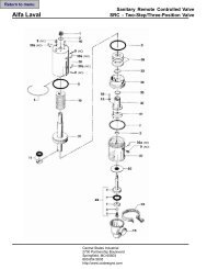
Exploded Drawing<br />
This page shows an exploded view of <strong>SPC</strong>-1.<br />
The drawing includes all items of the valve.<br />
They are identical <strong>with</strong> the items in the Spare Parts List.<br />
<strong>SPC</strong>-1<br />
16
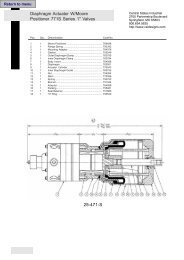
<strong>SPC</strong>-1<br />
Drawing/Parts List<br />
The drawing and the parts list include all items.<br />
NO = Normally open. NC = Normally closed.<br />
The items are identical <strong>with</strong> the items in the Spare Parts List.<br />
Please use this list when ordering.<br />
The drawing below shows <strong>SPC</strong>-1, NO and NC version.<br />
The items refer to the parts list on the opposite part of<br />
the page.<br />
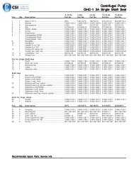
Parts List<br />
Item Qty. Description<br />
Actuator complete<br />
1 1 <strong>Valve</strong> positioner<br />
2 1 Air fitting<br />
3 2 Air fitting<br />
4 1 Spring support<br />
5 Δ 1 O-ring<br />
6 Δ 2 O-ring<br />
7 1 Cylinder<br />
8 Δ 1 O-ring<br />
9 1 Piston<br />
10 Δ 1 Lock wire<br />
11 Δ 1 Clip complete<br />
12 1 Spring assembly<br />
Item Qty. Denomination<br />
13 Δ 1 O-ring<br />
14 1 Bonnet<br />
15 1 Plug<br />
16 1 Air fitting<br />
17 1 Lip seal<br />
18 1 Plug complete<br />
18a 1 Plug<br />
18b 1 Seal<br />
18c 1 Plug head<br />
18d 1 O-ring<br />
18e 1 Bolt<br />
19 1 Clamp complete<br />
20 1 <strong>Valve</strong> body<br />
Δ : Service kit for actuator<br />
: Service kit - EPDM, NBR, FPM<br />
17<br />
NO<br />
NC
Information<br />
This page may be used for notes concerning the normal<br />
handling of the valve.<br />
The best way to produce user-friendly manuals is<br />
through feedback from the user.<br />
- Please see below.<br />
1. Notes<br />
...................................................................................................................................................................<br />
18<br />
...................................................................................................................................................................<br />
...................................................................................................................................................................<br />
...................................................................................................................................................................<br />
...................................................................................................................................................................<br />
...................................................................................................................................................................<br />
...................................................................................................................................................................<br />
...................................................................................................................................................................<br />
...................................................................................................................................................................<br />
...................................................................................................................................................................<br />
...................................................................................................................................................................<br />
...................................................................................................................................................................<br />
...................................................................................................................................................................<br />
...................................................................................................................................................................<br />
...................................................................................................................................................................<br />
...................................................................................................................................................................<br />
...................................................................................................................................................................<br />
...................................................................................................................................................................<br />
...................................................................................................................................................................<br />
...................................................................................................................................................................<br />
...................................................................................................................................................................<br />
...................................................................................................................................................................<br />
...................................................................................................................................................................<br />
...................................................................................................................................................................<br />
...................................................................................................................................................................<br />
2. User feedback<br />
Our goal is to produce instruction manuals that<br />
meet your needs.<br />
If you have any comments which may help us in<br />
our efforts to improve this manual, please do not<br />
hesitate to send them to us.<br />
Alfa Laval Inc.<br />
Tel. (800) 558-4060<br />
Fax. (800) 781-2777<br />
Questions? Please contact:<br />
Alfa Laval, Inc.<br />
9560 - 58th Place, Suite 300<br />
Kenosha, WI 53144<br />
www.alfalaval.us<br />
Thank you!