Travelling Wave Tube Amplifiers (TWTAs) for Space Applications
Travelling Wave Tube Amplifiers (TWTAs) for Space Applications
Travelling Wave Tube Amplifiers (TWTAs) for Space Applications

You also want an ePaper? Increase the reach of your titles
YUMPU automatically turns print PDFs into web optimized ePapers that Google loves.
<strong>Travelling</strong><br />
<strong>Wave</strong> <strong>Tube</strong><br />
<strong>Amplifiers</strong><br />
(<strong>TWTAs</strong>) <strong>for</strong><br />
<strong>Space</strong><br />
<strong>Applications</strong><br />
<strong>Travelling</strong> <strong>Wave</strong> <strong>Tube</strong> <strong>Amplifiers</strong><br />
from Bosch –<br />
<strong>for</strong> more than 4 million operating hours<br />
in space without failure<br />
The right connection.
30 years of experience<br />
enable Bosch to provide<br />
successful <strong>Travelling</strong> <strong>Wave</strong><br />
<strong>Tube</strong> <strong>Amplifiers</strong> (TWTA) <strong>for</strong><br />
space applications.<br />
The rapid growth of the<br />
space communications<br />
market during the last few<br />
years demanded <strong>for</strong> TWTA<br />
of high efficieny, ultimate<br />
bandwidth of about 2 GHz<br />
including flat responses,<br />
small dimensions and low<br />
masses.<br />
In a lot of communications<br />
satellites Bosch <strong>TWTAs</strong> have<br />
now accumulated more than<br />
4 million operating hours in<br />
space without failure. TWTA<br />
lifetimes of up to 15 years<br />
are usual.<br />
<strong>Travelling</strong> <strong>Wave</strong> <strong>Tube</strong> <strong>Amplifiers</strong><br />
(<strong>TWTAs</strong>) <strong>for</strong> <strong>Space</strong> <strong>Applications</strong><br />
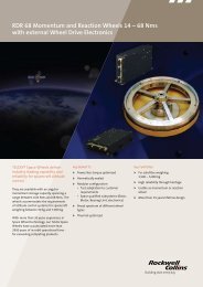
Bosch has provided <strong>TWTAs</strong><br />
which satisfied requirements of<br />
NASA, ESA, Intelsat, Inmarsat,<br />
European, Asian and US commercial<br />
programs. A wide variety<br />
of applications were covered<br />
by these <strong>TWTAs</strong>. Starting from<br />
frequencies at 1.5 GHz up to the<br />
Ka-band at 30 GHz <strong>TWTAs</strong> are<br />
on hand with RF output power<br />
ranges from 10 W up to 450 W.<br />
The flexible designs of the Bosch<br />
<strong>TWTAs</strong> give reply to utmost demands<br />
in satellite bus variation,<br />
power supply requirements,<br />
automatic restart, input current<br />
limiter, helix current and other<br />
protection functions.<br />
The Electronic Power Conditioner<br />
(EPC) of the TWTA is<br />
designed to be integrated with<br />
any <strong>Travelling</strong> <strong>Wave</strong> <strong>Tube</strong><br />
(TWT) existing <strong>for</strong> space communications<br />
applications by<br />
converting the spacecraft bus<br />
voltages into the high voltages<br />
required <strong>for</strong> TWT operation.<br />
A sophisticated design, qualified<br />
in various versions, flexible <strong>for</strong><br />
any satellite bus interface such<br />
as TM/TC, main bus voltage,<br />
thermal and mechanical, enable<br />
Bosch to manufacture <strong>TWTAs</strong><br />
<strong>for</strong> all purposes.<br />
Even the demand <strong>for</strong> high linearized<br />
transmission requirements<br />
can be realized with Linearized<br />
<strong>Travelling</strong> <strong>Wave</strong> <strong>Tube</strong> <strong>Amplifiers</strong><br />
(L<strong>TWTAs</strong>) using tunable<br />
linearizers and channel amplifiers<br />
developed by Bosch.<br />
Eurasiasat Ku-Band TWTA<br />
2
Description of the <strong>Travelling</strong><br />
<strong>Wave</strong> <strong>Tube</strong> Amplifier<br />
The TWTA is a very complex<br />
equipment and a key element<br />
of a satellite transponder. High<br />
efficiency is required in order to<br />
optimize RF output power and<br />
heat dissipation.<br />
The RF per<strong>for</strong>mance characteristics<br />
such as high gain, gain<br />
flatness, low phase distortion<br />
and high linearity shall be combined<br />
with straight <strong>for</strong>ward mechanical<br />
design which results in<br />
low mass and small dimensions.<br />
The <strong>TWTAs</strong> consist of the<br />
<strong>Travelling</strong> <strong>Wave</strong> <strong>Tube</strong> (TWT)<br />
mainly determining the RF<br />
per<strong>for</strong>mance and the integrated<br />
Electronic Power Conditioner<br />
(EPC), designed and manufactured<br />
by Bosch, <strong>for</strong> power<br />
matching of the DC and bus<br />
interfaces.<br />
The Bosch EPC is designed to<br />
be integrated with any TWT of<br />
the different TWT manufacturers<br />
by optimizing the high<br />
voltages <strong>for</strong> the individual<br />
approaches.<br />
The integration of the TWT<br />
and EPC and the testing of the<br />
TWTA are per<strong>for</strong>med by Bosch.<br />
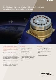
Based on the technology of the<br />
current TWTA programs Bosch<br />
developed a new line of EPCs<br />
<strong>for</strong> <strong>TWTAs</strong>. The family now<br />
covers the RF output power<br />
range from 10 W up to 150 W.<br />
The equipment are comprehensively<br />
qualification tested <strong>for</strong><br />
quite a number of applications.<br />
ATC-EPC with TWT<br />
3
Interfaces and specific features<br />
TM/TC interface<br />
TC TWTA-ON<br />
switches on the power supply<br />
and the TWTA is in its preheating<br />
phase. After the preheating<br />
time the high voltages <strong>for</strong> the<br />
TWT are automatically switched<br />
on and the TWTA is operational.<br />
TC TWTA-OFF<br />
– Status TWTA ON/OFF<br />
– Status restart enable/disable<br />
The following telemetries are<br />
provided:<br />
Analogue<br />
– Helix current<br />
– Anode voltage<br />
– Heater step (optional)<br />
– Input current (optional)<br />
Digital<br />
– Status TWTA ON/OFF<br />
– Status restart enable/disable<br />
Protections<br />
Helix overcurrent protections<br />
If the helix current exceeds the<br />
maximum value, the TWTA will<br />
be switched off. This protection<br />
can be disabled.<br />
LV Section<br />
V MB<br />
Input filter<br />
Startup regulator<br />
V MB<br />
Pre-regulator<br />
IF monitor<br />
V B<br />
Filament converter<br />
Linearizer/CAMP<br />
V Aux<br />
Supply voltage<br />
converter<br />
TM<br />
TC<br />
Telecommandtelemetryprotectionmodule<br />
V B<br />
monitor<br />
ON/OFF<br />
ON/OFF<br />
Power converter<br />
V A<br />
monitor<br />
I H<br />
monitor<br />
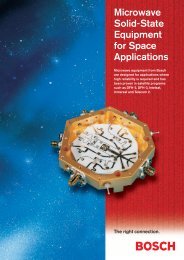
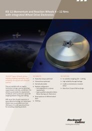
EPC Block diagram<br />
4
Pre-regulator undervoltage/<br />
overvoltage protection<br />
If the pre-regulator voltage<br />
drops below or exceeds its<br />
nominal value, the EPC is<br />
switched off.<br />
Main bus undervoltage<br />
protection<br />
If the main bus voltage drops<br />
below its specified range, the<br />
TWTA is switched off.<br />
Short circuit protection<br />
All high voltage outputs are<br />
short circuit protected.<br />
Specific features<br />
Cathode current control loop<br />
To eliminate any aging effect of<br />
the TWT the cathode current is<br />
kept constant. No degradation<br />
of output power will occur<br />
during lifetime. The regulation<br />
range of the anode voltage is<br />
about 10 %.<br />
Linearizer (Lin)/ Channel<br />
Amplifier (CAMP) supply V Aux<br />
(optional)<br />
To supply a linearizer or CAMP<br />
the EPC generates up to four<br />
short circuit protected outputs.<br />
HV Section<br />
Filament voltage<br />
generation<br />
F<br />
F K<br />
C 1<br />
C 2<br />
C 3<br />
C 4<br />
High voltage<br />
generation<br />
Cathode current<br />
regulator<br />
Output filter<br />
K<br />
A<br />
Helix regulator<br />
H<br />
5
The EPC is divided into<br />
functional blocks:<br />
Electronic Power Conditioner<br />
● TM/TC interface and<br />
protection circuits<br />
● Pre-regulator<br />
● Input filter and start-up<br />
regulator<br />
● Power converter<br />
● Filament converter<br />
● Filament voltage<br />
generation<br />
● High voltage generation<br />
● Helix regulator<br />
● Cathode current regulator<br />
● Output filter<br />
Description of<br />
Functional Modules<br />
The basic design concept is<br />
shown on the previous page.<br />
The unregulated main bus voltage<br />
(V MB ) is fed via a power<br />
switch to a pre-regulator which<br />
converts the variable input voltage<br />
into a constant output voltage<br />
(V B ). The main features of<br />
the regulator are high efficiency,<br />
good conducted susceptibility<br />
behaviour, high regulator loop<br />
stability and pulse load behaviour.<br />
An input filter suppresses voltage<br />
ripples from the main bus<br />
and switching noise from the<br />
EPC.<br />
LV section of EPC<br />
The constant output voltage<br />
(V B ) is directly applied to the<br />
filament converter, producing<br />
an AC voltage with square wave<br />
<strong>for</strong>m <strong>for</strong> the TWT heater.<br />
The power converter is also<br />
supplied by the constant voltage<br />
(V B ). The main features are high<br />
efficiency, suppression of high<br />
voltage trans<strong>for</strong>mer ringing,<br />
prevention of short circuit currents<br />
in the switching transistors<br />
and soft recovery <strong>for</strong> the high<br />
voltage diodes. This was achieved<br />
using a push-pull converter<br />
design patented by Bosch.<br />
An important part of the power<br />
chain is the high voltage generation<br />
which is achieved by a<br />
serial high voltage concept.<br />
The output voltage of the power<br />
converter is trans<strong>for</strong>med by one<br />
high voltage trans<strong>for</strong>mer and<br />
rectified by stacked doubler<br />
stages <strong>for</strong> collector helix and<br />
anode voltage.<br />
The helix voltage regulator and<br />
the cathode current regulator<br />
ensure a stable RF output power<br />
behaviour of the TWTA.<br />
The TWTA is equipped with an<br />
automatic restart. In the case of<br />
a protection circuit is triggered,<br />
the high voltages are switched<br />
off and only the heater voltage<br />
remains applied. After a period<br />
of 200 ms the supply voltages<br />
are reapplied to the tube and the<br />
amplifier is again operational.<br />
6
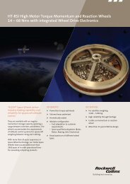
Dual TWTA – a cost and weight-effective solution<br />
The dual EPC is capable to<br />
operate two 140 W TWTs simultaneously.<br />
The two TWTs can be<br />
operated as single 140 W TWTA<br />
independently or RF combined<br />
in order to provide 270 W of<br />
RF output power from radiation<br />
cooled or conducted cooled<br />
TWTs.<br />
Key Per<strong>for</strong>mance Parameters<br />
Parameter<br />
Value<br />
Frequency<br />
10.70 – 12.75 GHz<br />
Output power<br />
120 W single<br />
240 W dual<br />
Efficiency<br />
59.5 % single<br />
60.6 % dual<br />
EPC<br />
94 % single<br />
EPC<br />
95 % dual<br />
Input power<br />
202 W single<br />
396 W dual<br />
Mass TWT 1100 gr<br />
EPC<br />
2200 gr<br />
Size TWT 375 x 72 (mm)<br />
Ø 110 mm collector<br />
EPC<br />
296 x 97 x 125 (mm)<br />
Dual TWTA<br />
7
The Microwave Power<br />
Module (MPM) is a compact<br />
amplifier consisting of<br />
Electronic Power Conditioner<br />
(EPC) with integrated<br />
Channel Amplifier (CAMP)<br />
and Linearizer (LIN).<br />
It provides many advantages<br />
as savings in mass, mounting<br />
area and harness simplification<br />
in payload integration,<br />
as well as better EMC<br />
characteristics and limitation<br />
to a unique connection to<br />
the EPC <strong>for</strong> DC and all<br />
TC/TM functions of the MPM.<br />
Microwave Power Module (MPM)<br />
Advantages of the MPM in comparison<br />
to separate equipment<br />
● Management reduction<br />
– one overall specification<br />
– one supplier has to be<br />
managed<br />
● Risk reduction<br />
– no interface problems on<br />
repeater level (complete<br />
measurement on EQ-level)<br />
– no EMC problems between<br />
CAMP/LIN and EPC or<br />
TC/TM box<br />
– no additional margin<br />
allocation<br />
● Mass reduction<br />
– no TC/TM and DC harness<br />
between CAMP/LIN and<br />
EPC or TC/TM box<br />
● Schedule reduction<br />
– simplified mounting on<br />
repeater panel<br />
– no TC/TM and DC harness<br />
between CAMP/LIN and<br />
EPC or TC/TM box<br />
Also available as Dual Linearized<br />
Channel TWTA (DLCT).<br />
DLCT – Key Per<strong>for</strong>mance Parameters<br />
P out RF<br />
2 x 113 W<br />
P in DC<br />
< 400 W<br />
P in RF<br />
– 58 dBm (2x)<br />
Dynamic range 30 dB with 1 dB/step (60 dB OPA optional)<br />
Operation<br />
ALC, FGM (OPA optional)<br />
V MB<br />
100 V<br />
Mass<br />
2940 g (without TWT)<br />
Dimensions 296 x 115 x 125 (mm 3 ) (without TWT)<br />
Dual MPM<br />
(DLCT)<br />
8
Our EPC Heritage<br />
TV-Sat, TDF, TELE-X, FEP, DFS, TDRSS<br />
serial HV generation / new helix regulator / fully milled housing<br />
MPA 100 ESTEC Con. 7174 / 87<br />
TELECOM<br />
INTELSAT<br />
new pre-regulator / new cathode curent regulator / new HV trans<strong>for</strong>mer<br />
MPA 130 ESTEC Con. 7174 / 87<br />
HISPASAT<br />
COLUMBUS<br />
IRS<br />
SMD (passive)<br />
DRS ESTEC Con. 8526 / 89<br />
new power design / ASIC<br />
CCN 130 ESTEC Con. 7173 / 87<br />
modified ASIC SMD<br />
(active), new mechanical<br />
concept, critical pressure<br />
capability, flexible HV<br />
design<br />
AMOS COLUMBUS INSAT<br />
ASIASAT TEMPO NAHUEL APSTAR<br />
AT-EPC<br />
Bosch Internal Program<br />
THAICOM<br />
HOTBIRD<br />
WORLD-<br />
STAR<br />
EUTELSAT<br />
W24<br />
SIRIUS<br />
SESAT<br />
CHINA-<br />
STAR<br />
ARTEMIS EOS ARABSAT<br />
TELECOM<br />
II / F4<br />
AT-EPC<br />
Dual TWTA<br />
Bosch<br />
Internal Program<br />
TEMPO PANAMSAT PIONEER<br />
DBSC 1/2 WHITETAIL TELSTAR<br />
MABUHAY<br />
ATC-EPC Bosch<br />
Internal Program<br />
INTELSAT<br />
FOS II<br />
DLCT<br />
Bosch<br />
Internal Program<br />
L-STAR<br />
9
Our TWTA Experience<br />
Project Supply Output Frequency Mass (g) Contract Remarks*<br />
Voltage Power Range scope/<br />
(Volt) (Watt) (GHz) TWTA EPC /h (%) launch date<br />
SYMPHONIE 27 ± 1 % 13 3.7 to 4.2 1670 1000 FM /1974<br />
ANIK B 22.5 to 33.5 10 3.7 to 4.2 2100 1400 FM /1978<br />
ANIK B 22.5 to 33.5 20 11.7 to 12.5 2190 1500 FM /1978<br />
Comsat Dev. 60 ± 1 % 6/12 3.7 to 12.5 2400 1800 BB /- Dual-mode TWTA<br />
Nat. Programme 50 ± 2 % 20 10.95 to 11.7 2240 1600 BB /- RC<br />
COMSAT 50 + 2 % / –3 % 230 11.7 to 12.5 12000 8500 EM /- Eclipse test of TWT, RC<br />
Nat. Programme 50 + 2 % / –3 % 450 11.7 to 12.5 15000 10000 EM /-<br />
UNISAT 42 ± 2 % 230 11.7 to 12.5 12000 7500 / 89 % EM /- CCR, RC<br />
TDRSS 1-6 22 to 43 30 11.7 to 14.05 3350 2650 / 78 % FM /1983<br />
FEP 20 to 60 22 20.2 to 21.2 3600 2400 / 79 % FM /1986 CCR and HS<br />
INMARSAT 50 +2 % / –3 % 358 1.5375 20500 8500 EM /- Linear. TWTA, CCR, RC<br />
TV-SAT 1 50 +2 % / –3 % 230 11.7 to 12.5 12000 8500 / 89 % FM /1988 CCR and ARU, RC<br />
TDF-1 50 +2 % / –3 % 260 11.7 to 12.5 12000 8500 / 89 % FM /1988 CCR and ARU, RC<br />
TELE-X 50 +2 % / –3 % 230 11.7 to 12.5 12000 8500 / 89 % FM /1989 CCR and ARU, RC<br />
TV-SAT2 50 ± 2 % 230 11.7 to 12.5 12000 7500 / 89 % FM /1989 CCR and ARU, RC<br />
TDF-2 50 ± 2 % 260 11.7 to 12.5 12000 7500 / 89 % FM /1989 CCR and ARU, RC<br />
DFS 26 to 43 20 11.45 to 11.7 2750 1850 / 81 % FM /1989 CCR<br />
DFS 26 to 43 20 12.5 to 12.75 2750 1850 / 81 % FM /1989 CCR<br />
DFS 26 to 43 20 19.7 to 20.1 3000 1950 / 82 % FM /1989 CCR<br />
ECS 50 ± 2 % 20 10.95 to 11.7 2750 1850 FM /1988 CCR<br />
Nat. Programme 27 to 43 37 10.95 to 12.75 3000 2100 / 85 % EM /- CCR<br />
Nat. Programme 27 to 43 60 10.95 to 12.75 3200 2300 / 86 % EM /- CCR<br />
EUTELSAT II 27 to 43 50 10.95 to 12.75 3500 2450 / 86 % FM /1990 CCR and HS<br />
110 W TWTA 42 +1 % / –2 % 110 11.7 to 12.75 3800 2450 / 90 % EMQ/- CCR and HS, prequalif.<br />
130 W TWTA 26.5 to 42.5 130 11.7 to 12.75 5000 2700 / 91 % EMQ/- CCR, ARU and HS, RC<br />
TDRS 7 22 to 43 32 13.40 to 14.05 3300 2200 / 86 % FM /1990 CCR<br />
Telecom II 26 to 43 55 12.5 to 12.75 – 2400 / 87 % FM /1991 CCR, ARU, SPS<br />
Intelsat VII 26 to 43 35/50 10.9 to 12.75 3270 2400 / 88 % FM /1992 CCR, ARU, HS, SPS<br />
Hispasat 26 to 43 55 11.45 to 12.75 3500 2400 / 87 % FM /1992 CCR, ARU, SPS<br />
Hispasat 26 to 43 40 7 3500 2400 / 86 % FM /1992 CCR, ARU,<br />
Hispasat 26 to 43 110 11.45 to 12.75 4000 2650 / 90 % FM /1992 CCR, ARU, SPS<br />
IRS 28 to 42 40 8 – 2650 / 87 % FM /1993 CPO<br />
COMETS 35 to 50 30 23 – 2200 / 86 % FM /1995<br />
COLUMBUS PPF 21.5 to 35.5 53 27 3000 1650 / 88 % FM /1997 CCR, ARU<br />
COLUMBUS PPF 22 to 35.5 27 8 3300 2300 / 86 % FM /1997 CCR<br />
EUTELSAT II/F6 27 to 43 75 12 3300 2550 / 90 % FM /1995 CCR, ARU<br />
AMOS 25 to 41.5 35 12 2600 1600 / 89 % FM /1995 CCR, ARU, SPS, CPO<br />
ASIASAT 100 ± 3 115 12 2550 1600 / 93 % FM /1995 CCR, ARU, HS, SPS<br />
ARTEMIS 42 ± 1 35 23 2440 1600 / 91 % FM /1997 CCR, ARU<br />
ARTEMIS 42 ± 1 30 20 2500 1600 / 91 % FM /1997 CCR, ARU<br />
INSAT 26.5 to 42.5 55 6 – 1600 / 90 % FM /1995 CCR, ARU<br />
EOS 24 to 32 20 14 2500 1600 / 88 % FM /1998 CCR, ARU<br />
TEMPO 100 ± 3 2 x 113 12 4800 2400 / 93 % FM /1995 CCR, ARU, SPS, RC, DT<br />
ARABSAT 42 ± 1 93 12 – 1600 / 93 % FM /1996 CCR, ARU, SPS<br />
Telecom II/F4 26 to 42 55 12 – 1600 /90 % FM /1996 CCR, ARU, SPS<br />
Telecom II/F4 26 to 42 40 6 – 1600 /89 % FM /1996 CCR, ARU, SPS<br />
MGS 24 to 32 25 8 – 1600 /88 % FM /1996 CCR, ARU<br />
Turksat F3 26 to 42 55 12 2400 1600 /90 % FM /1996 CCR, ARU, SPS<br />
10
Project Supply Output Frequency Mass (g) Contract Remarks*<br />
Voltage Power Range scope/<br />
(Volt) (Watt) (GHz) TWTA EPC /h (%) launch date<br />
Hotbird Plus 26 to 42 110 12 2650 1800 /93 % FM /1996 CCR, ARU, SPS<br />
Hotbird 3 26 to 42 110 12 2650 1800 /93 % FM /1997 CCR, ARU, SPS<br />
PanAmSat 6 100 ± 3 2 x (80–100) 12 4800 2400 /93 % FM /1997 CCR, ARU, SPS, RC, DT<br />
PanAmSat 6 100 ± 3 35 12 2400 1600 /89 % FM /1997 CCR, ARU<br />
Nahuel 26 to 42 55 12 2400 1600 /90 % FM /1997 CCR, ARU, SPS<br />
Mabuhay 1/2 100 ± 3 2 x 115 12 4400 2300 /93 % FM /1997 CCR, ARU, SPS, RC, DT<br />
Telstar 100 ± 3 2 x 100 12 4700 2300 /93 % FM /1997 CCR, ARU, SPS, RC, DT<br />
APSTAR 100 ± 3 2 x 113 12 4400 2300 /93 % FM /1996 CCR, ARU, SPS, RC, DT<br />
APSTAR 100 ± 3 60 4 2450 1600 /92 % FM /1996 CCR, ARU, SPS<br />
Thaicom 42 ± 1 97 12 2450 1600 /93 % FM /1997 CCR, ARU, SPS<br />
DBSC1 70 2 x 120 12 4400 2300 /93 % FM /1998 CCR, ARU, SPS, RC, DT<br />
CHINASTAR 70 135 R 12 2750 1800 /93 % FM /1998 CCR, ARU, SPS, RC<br />
Hotbird 4/5 26 to 42 135 12 2650 1800 /93 % FM /1998 CCR, ARU, SPS<br />
SIRIUS 1/2 50 ± 2 88 / 52 12 2450 1600 /93 % FM /1998 CCR, ARU, SPS<br />
PIONEER 1 100 2 x 110 12 4400 2300 /93 % FM /1998 CCR, ARU, SPS, RC, DT<br />
PIONEER 2 100 2 x 125 12 4400 2300 /93 % FM /1998 CCR, ARU, SPS, RC, DT<br />
Eutelsat III 50 90 /100 12 2400 1600 /93 % FM /1998 CCR, ARU, SPS<br />
PanAmSat 7 100 2 x 10⁷ 12 4400 2300 /93 % FM /1997 CCR, ARU, SPS, RC, DT<br />
PanAmSat 8 100 2 x 10⁷ 12 4400 2300 /93 % FM /1998 CCR, ARU, SPS, RC, DT<br />
Whitetail 1 70 2 x 120 12 4400 2300 /93 % FM /1998 CCR, ARU, SPS, RC, DT<br />
Whitetail 2 70 135 R 12 2750 1800 /93 % FM /1998 CCR, ARU, SPS, RC<br />
Sesat 35 to 42 95 12 2450 1600 /93 % FM /1998 CCR, ARU, SPS<br />
Worldstar 26 to 42 150 1.6 3800 1800 /93 % FM /1998 CCR, ARU, SPS<br />
L-STAR 100 2 x 113 12 5000 2200 /93 % FM /1998 MPM<br />
USSB 70 2 x 100 12 4400 2300 /93 % FM /1999 CCR, ARU, SPS, DT<br />
TELSTAR 7 100 2 x 120 12 4400 2300 /93 % FM /1999 CCR, ARU, SPS, RC, DT<br />
Echostar 4 70 2 x 120 R 12 4400 2300 /93 % FM /1999 CCR, ARU, SPS, RC, DT<br />
Intelsat K-TV 26 to 42 110 12 2650 1800 /93 % FM /1999 CCR, ARU, SPS, RC, DT<br />
ARABSAT 2 BSS 50 140 12 2450 1600 /93 % FM /1999 CCR, ARU, SPS<br />
ASTRA 2B 26 to 42 110 12 2650 1800 /93 % FM /1999 CCR, ARU, SPS<br />
Intelsat 9 100 100 R 12 2350 1400 /93 % FM /1999 CCR, ARU, SPS<br />
Intelsat 9 100 45–65 4 2150 1350 /93 % FM /1999 CCR, ARU, SPS<br />
Koreasat 3 70 85 20.5 2400 1600 /93 % FM /1999 CCR, ARU, SPS<br />
Hispasat 1C 26 to 42 110 12 2650 1800 /93 % FM /1999<br />
Chinasat 100 2 x120 12 4400 2300 /94% FM /1999 CCR, ARU, SPS, DT, RC<br />
EOS2 22 to 40 25 8 2400 1600 /90 % FM /1999 CCR, ARU<br />
Astra 1K Ka-band 50 63 20 2200 1350 /93 % FM/2000 CCR, ARU, SPS<br />
Astra 1K Ku-band 50 105 12 2200 1350 /93 % FM/2000 CCR, ARU, SPS, RC<br />
Eurasiasat Ku-band 50 106 12 2200 1350 / 93 % FM/2000 CCR, ARU, SPS, RC<br />
Eurasiasat X-band 50 114 7.5 3000 1600 / 93 % FM/2000 CCR, ARU, SPS, RC<br />
AMRC 100 216 2.3 3450 1630 /94% FM/2000 CCR, ARU, SPS<br />
EuropeStar 100 140 12 2700 1630 /94% FM/2000 CCR, ARU, SPS, RC<br />
GE-2A 70 2 x120 12 4400 2300 /94% FM/2001 CCR, ARU, SPS, RC, DT<br />
INSAT 3 C-band 26 to 43 63 4 2400 1600 /91% FM/2000 CCR, ARU, SPS, CPO<br />
INSAT 3 S-band 26 to 43 70 2.5 2400 1600 /91% FM/2000 CCR, ARU, SPS, CPO<br />
INSAT 3 Ku-band 26 to 43 70 12 – 1600 /91% FM/2000 CCR, ARU, SPS, CPO<br />
* Remarks: CCR = Cathode Current Regulation, SPS = Secondary Power Supply, ARU = Automatic Restart Units, CPO = Critical Pressure<br />
Operation, HS = Heater Step, DT = Dual <strong>Tube</strong> Supply, RC = Radiation Cooled TWT, MPM = Microwave Power Module<br />
11
Our Representative in the USA<br />
and Canada:<br />
Peter Lüst<br />
Electronic Note <strong>Space</strong> Systems<br />
300 Esplanade Drive,<br />
9th floor, Suite 900,<br />
Oxnard, Cali<strong>for</strong>nia 93030,<br />
USA<br />
Telephone 805-981-9178<br />
Telefax 805-981-91 47<br />
Bosch Telecom GmbH<br />
<strong>Space</strong> Communication Systems<br />
D-71520 Backnang<br />
Federal Republic of Germany<br />
Telephone +49 71 91 13-21 84<br />
Telefax +49 71 91 13-34 22<br />
www.bosch-telecom.com<br />
© Bosch Telecom GmbH . 776841 . Specifications subject to change . Printed in the Federal Republic of Germany . 06.99