CANOpen Network CAN Bus Cabling Guide - Advanced Motion ...
CANOpen Network CAN Bus Cabling Guide - Advanced Motion ...
CANOpen Network CAN Bus Cabling Guide - Advanced Motion ...

Create successful ePaper yourself
Turn your PDF publications into a flip-book with our unique Google optimized e-Paper software.
AN-005<br />
<strong>CAN</strong>open <strong>Network</strong> <strong>Bus</strong> <strong>Cabling</strong> <strong>Guide</strong><br />
Introduction<br />
<strong>CAN</strong> (Controller Area <strong>Network</strong>) is a two-wire<br />
differential serial communication protocol for realtime<br />
control. ADVANCED <strong>Motion</strong> Controls ® ’<br />
<strong>CAN</strong>open drives use the <strong>CAN</strong> Physical Layer as<br />
defined by the <strong>CAN</strong> in Automation (CiA)<br />
standards DS-102 V2.0.<br />
<strong>CAN</strong> <strong>Bus</strong> <strong>Cabling</strong><br />
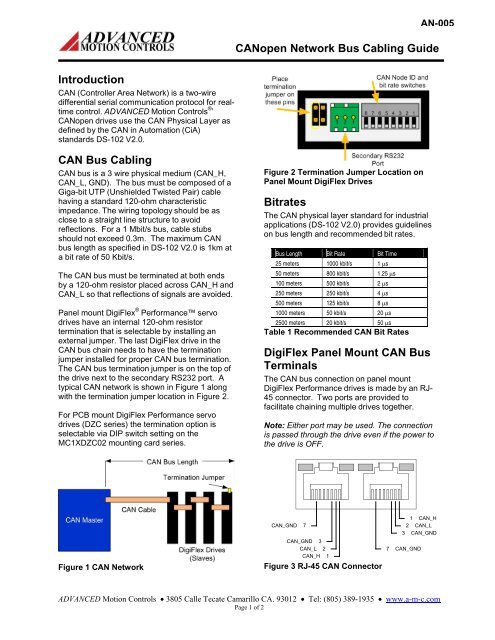
<strong>CAN</strong> bus is a 3 wire physical medium (<strong>CAN</strong>_H,<br />
<strong>CAN</strong>_L, GND). The bus must be composed of a<br />
Giga-bit UTP (Unshielded Twisted Pair) cable<br />
having a standard 120-ohm characteristic<br />
impedance. The wiring topology should be as<br />
close to a straight line structure to avoid<br />
reflections. For a 1 Mbit/s bus, cable stubs<br />
should not exceed 0.3m. The maximum <strong>CAN</strong><br />
bus length as specified in DS-102 V2.0 is 1km at<br />
a bit rate of 50 Kbit/s.<br />
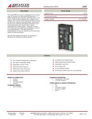
The <strong>CAN</strong> bus must be terminated at both ends<br />
by a 120-ohm resistor placed across <strong>CAN</strong>_H and<br />
<strong>CAN</strong>_L so that reflections of signals are avoided.<br />
Panel mount DigiFlex ® Performance servo<br />
drives have an internal 120-ohm resistor<br />
termination that is selectable by installing an<br />
external jumper. The last DigiFlex drive in the<br />
<strong>CAN</strong> bus chain needs to have the termination<br />
jumper installed for proper <strong>CAN</strong> bus termination.<br />
The <strong>CAN</strong> bus termination jumper is on the top of<br />
the drive next to the secondary RS232 port. A<br />
typical <strong>CAN</strong> network is shown in Figure 1 along<br />
with the termination jumper location in Figure 2.<br />
For PCB mount DigiFlex Performance servo<br />
drives (DZC series) the termination option is<br />
selectable via DIP switch setting on the<br />
MC1XDZC02 mounting card series.<br />
Figure 2 Termination Jumper Location on<br />
Panel Mount DigiFlex Drives<br />
Bitrates<br />
The <strong>CAN</strong> physical layer standard for industrial<br />
applications (DS-102 V2.0) provides guidelines<br />
on bus length and recommended bit rates.<br />
<strong>Bus</strong> Length Bit Rate Bit Time<br />
25 meters 1000 kbit/s 1 µs<br />
50 meters 800 kbit/s 1.25 µs<br />
100 meters 500 kbit/s 2 µs<br />
250 meters 250 kbit/s 4 µs<br />
500 meters 125 kbit/s 8 µs<br />
1000 meters 50 kbit/s 20 µs<br />
2500 meters 20 kbit/s 50 µs<br />
Table 1 Recommended <strong>CAN</strong> Bit Rates<br />
DigiFlex Panel Mount <strong>CAN</strong> <strong>Bus</strong><br />
Terminals<br />
The <strong>CAN</strong> bus connection on panel mount<br />
DigiFlex Performance drives is made by an RJ-<br />
45 connector. Two ports are provided to<br />
facilitate chaining multiple drives together.<br />
Note: Either port may be used. The connection<br />
is passed through the drive even if the power to<br />
the drive is OFF.<br />
Figure 1 <strong>CAN</strong> <strong>Network</strong><br />
<strong>CAN</strong>_GND 7<br />
<strong>CAN</strong>_GND 3<br />
<strong>CAN</strong>_L 2<br />
<strong>CAN</strong>_H 1<br />
Figure 3 RJ-45 <strong>CAN</strong> Connector<br />
7<br />
1 <strong>CAN</strong>_H<br />
2 <strong>CAN</strong>_L<br />
3 <strong>CAN</strong>_GND<br />
<strong>CAN</strong>_GND<br />
ADVANCED <strong>Motion</strong> Controls • 3805 Calle Tecate Camarillo CA. 93012 • Tel: (805) 389-1935 • www.a-m-c.com<br />
Page 1 of 2
AN-005<br />
<strong>CAN</strong>open <strong>Network</strong> <strong>Bus</strong> <strong>Cabling</strong> <strong>Guide</strong><br />
Pin Signal Description<br />
1 <strong>CAN</strong>_H <strong>CAN</strong>_H bus line (dominant high)<br />
2 <strong>CAN</strong>_L <strong>CAN</strong>_L bus line (dominant low)<br />
3 <strong>CAN</strong>_GND <strong>CAN</strong> Ground<br />
4 RESERVED Reserved<br />
5 RESERVED<br />
6 <strong>CAN</strong>_SHIELD No Connection (Pass Through)<br />
7 <strong>CAN</strong>_GND <strong>CAN</strong> Ground<br />
8 <strong>CAN</strong>_V+ No Connection (Pass Through)<br />
Table 2 RJ-45 Pinout<br />
MC1XDZC02 <strong>CAN</strong> <strong>Bus</strong> Terminal<br />
The MC1XDZC02 mounting card series for DZC<br />
drives uses a 10-port plug terminal for the <strong>CAN</strong><br />
bus.<br />
GND 5<br />
RS232 RX 3<br />
7 <strong>CAN</strong>_L IN<br />
RESERVED 1<br />
9 <strong>CAN</strong>_H IN<br />
Note: All drives must be configured to use the<br />
same bit rate, but each drive must have a unique<br />
Node ID.<br />
Troubleshooting<br />
Most problems are caused by improper<br />
connection, poor termination, wrong bit rate<br />
selection, or Node ID configuration.<br />
<strong>CAN</strong> card manufacturers provide <strong>CAN</strong> <strong>Bus</strong><br />
software to send and receive messages. This<br />
software is valuable for debugging a <strong>CAN</strong> bus.<br />
DigiFlex drives at power up send out a reset<br />
message. Upon initial setup, look for this<br />
message. If the bus is healthy, the message<br />
displayed has the form:<br />
0x700 + node ID Length 00<br />
For Node #1: 0x701 1 00<br />
RESERVED 2<br />
RS232 TX 4<br />
GND 6<br />
10 <strong>CAN</strong>_H OUT<br />
8 <strong>CAN</strong>_L OUT<br />
Figure 4 10-port Terminal Connector<br />
Pin Signal Description<br />
1 RESERVED Reserved<br />
2 RESERVED<br />
3 RS232 RX Receive Line (RS-232)<br />
4 RS232 TX Transmit Line (RS-232)<br />
5 GND Ground<br />
6 GND<br />
7 <strong>CAN</strong>_L IN <strong>CAN</strong>_L bus line (dominant low)<br />
8 <strong>CAN</strong>_L OUT<br />
9 <strong>CAN</strong>_H IN <strong>CAN</strong>_H bus line (dominant high)<br />
10 <strong>CAN</strong>_H OUT<br />
Table 3 10-port Terminal Pinout<br />
Note: This message is sent only at power up.<br />
Isolate the problem, then cycle drive power to<br />
send the message again.<br />
Use an ohm meter to check wiring. With the<br />
power off, verify 60 Ω across <strong>CAN</strong>_H and<br />
<strong>CAN</strong>_L. With the <strong>CAN</strong> bus on, use an<br />
oscilloscope to differentially measure the signal<br />
levels on the <strong>CAN</strong> bus. A two channel scope<br />
must be used. Set the scope to show both<br />
channels and set the math function to ADD. Also<br />
set the channel INVERT to ON. Send messages<br />
from the host to each node and verify the levels<br />
using Figure 5 below. Make sure signals are out<br />
of the invalid range and that rise times are < 15%<br />
of bit time.<br />
The MC1XDZC02 Node ID, <strong>CAN</strong>open Bit Rate,<br />
and Termination resistor are all set using DIP<br />
Switches on the mounting card PCB.<br />
<strong>CAN</strong> <strong>Bus</strong> Drive Setup<br />
ADVANCED <strong>Motion</strong> Controls’ <strong><strong>CAN</strong>Open</strong> drives<br />
have hardware or software configurable bit rate<br />
and node id settings. All drives ship with their<br />
DIP Switches all ‘OFF’ or ‘UP’ for software<br />
addressing. It is recommended during initial<br />
setup to configure all drives’ bit rate with the<br />
hardware switches and set each drive with a<br />
unique node ID via the hardware switches.<br />
Figure 5 <strong>CAN</strong> Voltage Levels<br />
ADVANCED <strong>Motion</strong> Controls • 3805 Calle Tecate Camarillo CA. 93012 • Tel: (805) 389-1935 • www.a-m-c.com<br />
Page 2 of 2