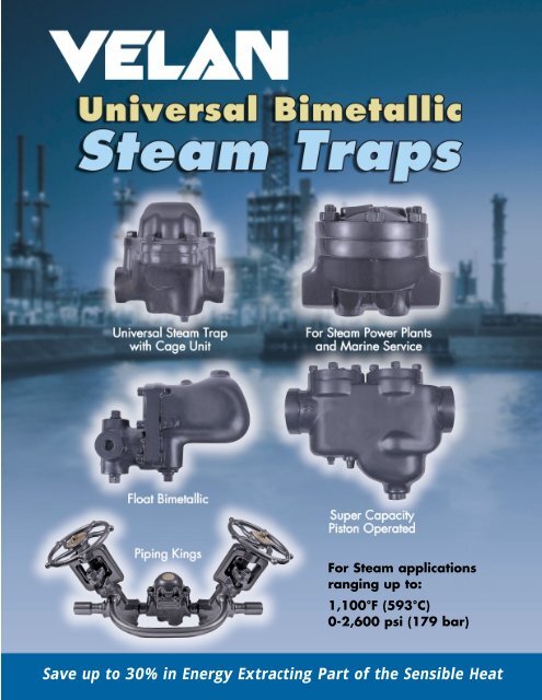
Velan Universal Bimetallic Steam Traps
Velan Universal Bimetallic Steam Traps
Velan Universal Bimetallic Steam Traps

Create successful ePaper yourself
Turn your PDF publications into a flip-book with our unique Google optimized e-Paper software.
For <strong>Steam</strong> applications<br />
ranging up to:<br />
1,100°F (593°C)<br />
0-2,600 psi (179 bar)<br />
Save up to 30% in Energy Extracting Part of the Sensible Heat
VELAN COMPANY PROFILE<br />
<strong>Velan</strong> is one of the world's leading manufacturers of industrial valves,<br />
supplying forged and cast steel gate, globe, check, ball, butterfly, knife gate<br />
and engineered severe service valves for critical applications in power,<br />
chemical and petrochemical, oil and gas, pulp and paper, mining, marine,<br />
cryogenic and general construction industries.<br />
Founded in 1950, <strong>Velan</strong> earned a reputation for excellence as a major supplier<br />
of forged valves to nuclear power plants and the U.S. Navy. <strong>Velan</strong> has<br />
pioneered many innovative valve designs, emphasizing quality, safety, ease<br />
of operation, low emissions, simple in-line maintenance and long cycle life.<br />
<strong>Velan</strong>’s 21 product lines are manufactured in 12 specialized manufacturing<br />
plants, including six in Canada and U.S.A., three in Europe, and three in Asia.<br />
We have 1,500 employees, 75% of whom are located in our North American<br />
operations.<br />
THE ORIGINAL VELAN STEAM TRAP<br />
<strong>Velan</strong> is pleased to announce that we have<br />
reacquired the <strong>Velan</strong> universal steam trap<br />
line produced for 15 years by Plenty <strong>Steam</strong><br />
Products. This comprehensive range of steam<br />
traps is based on a unique design that was<br />
developed and patented by A.K. <strong>Velan</strong>,<br />
President and CEO of <strong>Velan</strong> Inc., and is now<br />
copied by major steam trap manufacturers.<br />
Once again, you can trust <strong>Velan</strong> to supply<br />
high quality steam traps for virtually all of<br />
your condensate drainage applications.<br />
CONTENTS<br />
Manufacturing Plants ..........................................1<br />
Principles of Operation.................................... 2, 3<br />
How it Works......................................................4, 5<br />
Forged <strong>Universal</strong> <strong>Bimetallic</strong> <strong>Steam</strong> <strong>Traps</strong><br />
Types TS, TSF & SF .......................................... 6, 7<br />
<strong>Universal</strong> <strong>Bimetallic</strong> <strong>Steam</strong> <strong>Traps</strong><br />
Type SSF ............................................................ 8, 9<br />
Forged HP/HT <strong>Steam</strong> <strong>Traps</strong><br />
Type N ............................................................ 10, 11<br />
Hermetically Sealed <strong>Steam</strong> <strong>Traps</strong><br />
Type Q250 ...................................................... 12, 13<br />
High Capacity Piston Operated<br />
<strong>Steam</strong> <strong>Traps</strong> Type SPF & SP....................... 14, 15<br />
Piping King Package Units .......................... 16-19<br />
Monovalve Float <strong>Bimetallic</strong> <strong>Steam</strong> <strong>Traps</strong><br />
Type MFT & MFTS ....................................... 20-22<br />
Space Heating <strong>Steam</strong> <strong>Traps</strong> Type ACF ........... 23<br />
Thermodynamic <strong>Steam</strong> <strong>Traps</strong><br />
Type HPTD, PTD & VTS ............................... 24, 25<br />
Compressed Air Drain <strong>Traps</strong><br />
Type MFA & MFAS ...................................... 26, 27<br />
Strainers............................................................... 28<br />
Accessories..........................................................29<br />
Comparison of Principles of Operation ...........31<br />
Selection - Sizing ................................................32<br />
How to Order ....................................................... 33<br />
HEAD OFFICE & PLANT 5<br />
MONTREAL, CANADA 115,000 sq. ft. (10,683 m 2 )<br />
3 – 24” (80 –600 mm) butterfly, 3 ⁄8 – 4” (10 –100 mm) metal & resilient seated ball valves<br />
MANUFACTURING LOCATIONS<br />
CANADA<br />
VELAN INC.<br />
HEAD OFFICE & PLANT 5<br />
7007 Côte de Liesse<br />
Montreal, QC H4T 1G2<br />
Tel: (514) 748-7743<br />
Fax: (514) 748-8635<br />
PLANT 1<br />
2125 Ward Avenue<br />
Montreal, QC H4M 1T6<br />
Tel: (514) 748-7743<br />
Fax: (514) 748-8635<br />
PLANT 2 / 7<br />
550 McArthur Ave.<br />
Montreal, QC H4T 1X8<br />
Tel: (514) 748-7743<br />
Fax: (514) 341-3032<br />
PLANT 4 / 6<br />
1010 Cowie Street<br />
Granby, QC J2J 1E7<br />
Tel: (450) 378-2305<br />
Fax: (450) 378-6865<br />
PROQUIP<br />
835 Fourth Line<br />
Oakville, ON L6L 5B8<br />
Tel: (905) 842-1721<br />
Fax: (905) 849-0923<br />
U.S.A.<br />
VELAN VALVE<br />
CORPORATION<br />
PLANT 3<br />
94 Avenue C<br />
Williston, VT 05495-9732<br />
Tel: (802) 863-2562<br />
Fax: (802) 862-4014<br />
ENGLAND<br />
VELAN VALVES LTD.<br />
Unit 1, Pinfold Road<br />
Lakeside Business Park<br />
Thurmaston<br />
Leicester LE4 8AS<br />
Tel: 44-116 269-5172<br />
Fax: 44-116 269-3695<br />
FRANCE<br />
VELAN S.A.S<br />
90, rue Challemel Lacour<br />
F 69 367 Lyon Cedex 7<br />
Tel: (33) 4 78 61 67 00<br />
Fax: (33) 4 78 72 12 18<br />
PORTUGAL<br />
VELAN VÁLVULAS<br />
INDUSTRIAIS, LDA.<br />
Av. Ary dos Santos<br />
1679-018 Famoes<br />
Tel: (351-21) 934-7800<br />
Fax: (351-21) 934-7809<br />
TAIWAN<br />
VELAN-VALVAC<br />
P.O. Box 2020<br />
Taichung, Taiwan<br />
R.O.C.<br />
Tel: (04) 2792649<br />
Fax: (886) 42750855<br />
KOREA<br />
VELAN LTD.<br />
1060-4 Shingil-Dong<br />
Ansan City,<br />
Kyunggi-do 425-833<br />
Tel: (82) 31-491-2811<br />
Fax: (82) 31-491-2813<br />
DISTRIBUTION CENTERS<br />
U.S.A.<br />
VELCAL<br />
537 Stone Road, Unit "A"<br />
Benicia, CA 94510<br />
Tel: (707) 745-4507<br />
Fax: (707) 745-4708<br />
VELEAST<br />
605 Commerce<br />
Park Drive SE<br />
Marietta, GA 30060<br />
Tel: (770) 420-2010<br />
Fax: (707) 420-7063<br />
GERMANY<br />
VELAN GmbH<br />
Daimlerstrasse 8<br />
D-47877 Willich<br />
Tel: (49) 2154/4938-00<br />
Fax: (49) 2154/4938-99<br />
Visit the <strong>Velan</strong> website at www.velan.com for an updated contact list.<br />
<strong>Velan</strong> has sales offices and distributors located worldwide.<br />
GENERAL<br />
INFORMATION<br />
Tel: 44-116 269-5172<br />
Fax: 44-116 269-3695<br />
steamtraps@velan.com<br />
NOTE: The material in this catalog is for general information. For specific performance data and proper material selection, consult your<br />
<strong>Velan</strong> representative. Although every attempt has been made to ensure that the information contained in this catalog is correct,<br />
<strong>Velan</strong> reserves the right to change designs, materials or specifications without notice.
MANUFACTURING PLANTS AROUND THE WORLD<br />
PLANT 1<br />
PLANT 3<br />
MONTREAL, CANADA 109,000 sq. ft. (10,126 m 2 ) 1 ⁄4 –4” (8 –100 mm)<br />
forged gate, globe & check valves, ASME ‘N’ stamp, ISO 9001<br />
PLANT 2 & 7<br />
WILLISTON, VERMONT, U.S.A. 155,000 sq. ft. (14,400 m 2 )<br />
2 –24” (50–600 mm) forged and cast steel gate, globe and check<br />
valves, ASME ‘N’ stamp, ISO 9001<br />
MONTREAL, CANADA 170,000 sq. ft. (15,800 m 2 ) 2 – 60” (50–1500 mm)<br />
forged and cast steel gate, globe, check, ball, knife and butterfly<br />
valves 26–36” (650–700 mm) ASME ‘N’ stamp, ISO 9001<br />
PLANT 4 & 6<br />
LYON, FRANCE 160,000 sq. ft. (14,900 m 2 ) 1<br />
⁄4 –40” (8–1,000 mm)<br />
forged and cast steel gate, globe and butterfly valves, ISO 9001<br />
GRANBY, CANADA 186,500 sq. ft. (17,325 m 2 )<br />
2–12” (50 –300 mm) cast steel gate and check valves,<br />
1<br />
⁄4–12” (8–300 mm) ball valves, ISO 9001<br />
LISBON, PORTUGAL 60,000 sq. ft. (5,600 m 2 ) ISO 9002<br />
2–12” (50–300 mm) cast steel gate, globe and check valves<br />
TORONTO, CANADA <strong>Velan</strong>-Proquip 41,000 sq. ft. (3,800 m 2 )<br />
2– 48” (50 – 1200 mm) wafer check valves<br />
1<br />
⁄2– 24” (15 – 600 mm) clamp joint connectors, ISO 9001<br />
ANSAN CITY, SOUTH KOREA Plant 1 30,000 sq. ft. (2,800 m 2 )<br />
components and 2–4” (50–100 mm) cast steel valves, ISO 9002<br />
ANSAN CITY, SOUTH KOREA Plant 2 65,000 sq. ft. (5,800 m 2 )<br />
6–12” (150 –300 mm) cast steel gate, globe, check, ball<br />
and knife gate valves, ISO 9002<br />
WILLICH, GERMANY 12,000 sq. ft. (1,115 m 2 ) ISO 9002<br />
LEICESTER, ENGLAND 14,000 sq. ft. (1,300 m 2 ) ISO 9002, steam traps,<br />
3<br />
⁄8–2” (10–50 mm) bonnetless globe valves 1 ⁄2– 2” (15 – 50 mm)<br />
TAICHUNG, TAIWAN <strong>Velan</strong>-Valvac 20,000 sq. ft. (1,840 m 2 )<br />
1<br />
⁄4–2” (8–50 mm) ball valves, ISO 9002<br />
1
PRINCIPLES OF OPERATION<br />
The Original “<strong>Universal</strong>” Bimetal Principle<br />
Actuates <strong>Velan</strong> <strong>Steam</strong> <strong>Traps</strong><br />
WHAT IS BIMETAL?<br />
● Bimetal is a composite<br />
metal comprising two<br />
or more metallic<br />
layers with different<br />
coefficients of<br />
expansion, which<br />
changes curvature<br />
when subjected<br />
to heat.<br />
<strong>Velan</strong> <strong>Steam</strong> <strong>Traps</strong><br />
use a bimetal of<br />
high tensile<br />
strength, stable at<br />
high temperature<br />
with deflection<br />
limited to 600°F<br />
(315°C) to prevent<br />
over-stressing on<br />
super-heated<br />
steam service.<br />
THE CLOSING FORCE OF THE BIMETALLIC ELEMENTS<br />
FOLLOWS THE SATURATED STEAM CURVE<br />
The force of line pressure acting on the valve<br />
ball holds it open when condensate or air is in<br />
the trap. Line pressure, valve and orifice<br />
diameter determine this force. For a 1 /2”<br />
(12.7 mm) orifice at 150 psi (10.3 bar) line<br />
pressure develops a force of 30 lb (134 N).<br />
To close the valve on steam the bimetallic<br />
element must develop a pull of at least 35 lb<br />
(156 N) with three segments. The patented<br />
<strong>Velan</strong> multi-segment design was developed so<br />
that the thermal pull of the bimetal element<br />
would closely follow the saturated steam curve<br />
and use only the portion of the element<br />
required to overcome the opening force at<br />
saturated steam temperature.<br />
Chart 1 Operating Principle of <strong>Velan</strong> <strong>Steam</strong> <strong>Traps</strong><br />
300<br />
250<br />
200<br />
156<br />
134<br />
70<br />
60<br />
50<br />
40<br />
35<br />
30<br />
A 1<br />
A<br />
C 1 C<br />
B<br />
350<br />
300<br />
250<br />
200<br />
150<br />
25<br />
20<br />
15<br />
10<br />
A non-segmented bimetallic element would<br />
have a straight-line characteristic and the trap<br />
would only react to large temperature<br />
differentials, whereas the <strong>Velan</strong> segmented<br />
element automatically compensates for any<br />
pressure condition within its range, and<br />
maintains the sensitivity to release condensate<br />
at below steam temperature without loss of<br />
steam.<br />
Chart 1 illustrates the truly universal operating<br />
principle behind the <strong>Velan</strong> steam trap. Each<br />
segment acts consecutively, covering the<br />
complete operating pressure range without<br />
adjustment or orifice change. With a single<br />
element the temperature differential to open<br />
the steam trap would be BC 1 (66°F/37°C)<br />
instead of BC (8°F/4.4°C) and the required<br />
closing force would be BA 1 (20 lb/90 N) instead<br />
of BA (5 lb/22 N).<br />
100<br />
50<br />
0<br />
N<br />
Pull of Bimetal<br />
20<br />
10<br />
0<br />
lb<br />
Single element<br />
Multielement<br />
200 212 250 287 300 350 400 440<br />
100 142 150 200 225<br />
<strong>Steam</strong> Temperature<br />
1 2 3 4<br />
1. Free deflection up to 212°F (100°C)<br />
2. One segment pulling 0-40 psi (0-2.8 bar) up to 287°F (142°C)<br />
3. Two segments pulling 40-120 psi (2.28-8.3 bar) up to 350°F (177°C)<br />
4. Three segments pulling 120-350 psi (8.3-24 bar) up to 440°F (227°C)<br />
100<br />
50<br />
0<br />
psi<br />
<strong>Steam</strong> Pressure<br />
bar<br />
5<br />
0<br />
2
PRINCIPLES OF OPERATION<br />
The <strong>Velan</strong> Patented Bimetal Principle<br />
as Applied to Meet Various Requirements<br />
UNIVERSAL STEAM TRAP<br />
PRINCIPLE<br />
● Chart 2 illustrates the bimetal<br />
closing force developed at<br />
saturated temperature in relation<br />
to the line pressure tending to<br />
open the valve. The gradual<br />
increase in force, following the<br />
steam curve, is a function of the<br />
patented segmentation principle of<br />
the element. The delicate balance<br />
of opening and closing forces<br />
exists in all pressure ranges such<br />
as 0-200, 0-350, 0-600, 0-1500,<br />
500-2500 psi (0-14, 0-21, 0-41,<br />
0-103, 35-172 bar), and produces<br />
complete universal operation<br />
throughout the pressure range<br />
without adjustment or orifice<br />
change. See page 4 for<br />
more details.<br />
20<br />
15<br />
10<br />
5<br />
0<br />
300<br />
250<br />
200<br />
150<br />
100<br />
50<br />
0<br />
bar<br />
psi<br />
<strong>Steam</strong><br />
Pressure<br />
65<br />
100<br />
Element 1, 2 & 3<br />
Element 1 & 2<br />
Element 1<br />
150<br />
– 3<br />
– 2<br />
– 1<br />
200 250 300 350 400<br />
18 50 100 150 200<br />
<strong>Steam</strong> Temperature<br />
Chart 2 The patented Multi-element Principle.<br />
Saturated<br />
<strong>Steam</strong> Curve<br />
60<br />
50<br />
40<br />
30<br />
20<br />
10<br />
0<br />
lb<br />
250<br />
200<br />
150<br />
100<br />
50<br />
0N<br />
Element<br />
Closing<br />
Forces<br />
FLOAT BIMETALLIC<br />
PRINCIPLE<br />
● Chart 3 illustrates the operation of<br />
the combination of a bimetal and<br />
float element utilized in the<br />
float/bimetallic series. In this<br />
principle, the bimetal is used to<br />
close the valve at saturated<br />
temperature or release cool air<br />
in the system. However a small<br />
accumulation of condensate<br />
in the trap body lifts the float<br />
and opens the discharge valve.<br />
No temperature depression is<br />
required for this process and,<br />
as a result, the characteristic is<br />
identical to the saturated steam<br />
curve. The steam trap shuts off<br />
in the presence of steam and<br />
opens at once in the presence<br />
of condensate even at saturated<br />
steam temperature. See page 5<br />
for more details.<br />
15<br />
10<br />
5<br />
0<br />
200<br />
100<br />
0<br />
bar<br />
psi<br />
<strong>Steam</strong><br />
Pressure<br />
65<br />
100<br />
Saturated<br />
<strong>Steam</strong> Curve<br />
200 300 400<br />
18 50 100 150 200<br />
<strong>Steam</strong> Temperature<br />
Chart 3 The patented Multi-element Principle combined with a float.<br />
40<br />
30<br />
20<br />
10<br />
0<br />
lb<br />
200<br />
150<br />
100<br />
50<br />
0<br />
N<br />
Element<br />
Closing<br />
Forces<br />
3
HOW IT WORKS<br />
THE 4 PURPOSE VALVE AND ITS FUNCTION<br />
IN THE VELAN UNIVERSAL BIMETALLIC STEAM TRAP<br />
FAST WARM UP<br />
The discharge valve is open, allowing air and cold water<br />
to be discharged rapidly. The period of waiting to start<br />
a process is reduced to minutes – there is no air binding,<br />
water-logging or steam<br />
locking to delay equipment<br />
warm up.<br />
Actual tests show that up to<br />
2 1/ 2 hours may be saved on<br />
each “warm-up” because<br />
<strong>Velan</strong> <strong>Steam</strong> <strong>Traps</strong> have a<br />
much greater venting<br />
capacity than other traps,<br />
due to large orifice.<br />
POSITIVE TRAPPING<br />
Incoming steam causes the bimetal to deflect.<br />
This thermal pull of the bimetal element acts on the valve<br />
stem overcoming the steam pressure closing the valve.<br />
The ball valve is pulled tightly on to<br />
its seat preventing weeping<br />
and loss of live steam.<br />
The thermal pull increases<br />
or decreases as a function<br />
of temperature, in the<br />
same relation as the<br />
temperature and pressure<br />
of the saturated steam.<br />
The same element can be<br />
used for varying steam<br />
pressures within wide<br />
pressure ranges.<br />
TRAPPING<br />
I STEP<br />
DRAINING<br />
II STEP<br />
Acting Valve<br />
Area<br />
Thermal<br />
Pull<br />
Closing Force<br />
Unbalanced Pressure<br />
Opening Force<br />
Pressure<br />
Action<br />
On Orifice<br />
Pressure<br />
Action<br />
On Full<br />
Valve Area<br />
Differential<br />
Pressure<br />
Pressure<br />
Balanced<br />
Valve Closed<br />
Pressure Cracks<br />
Valve and<br />
Releases Flow<br />
Pressure Opens<br />
Valve Completely<br />
Acting On Full<br />
Valve Area<br />
TWO STEP DRAINAGE<br />
When steam condenses into water, the thermal pull of the<br />
bimetal is gradually reduced until the line pressure on the<br />
valve releases it from the valve seat and allows condensate<br />
to be discharged.<br />
This is the first step in the<br />
smooth and quick opening<br />
of the valve, without noise<br />
or violent action. When<br />
the flow is released, the<br />
unbalanced pressure acts<br />
on the full valve area.<br />
The force to overcome the<br />
thermal pull increases and<br />
opens the orifice to full<br />
capacity.<br />
CHECK VALVE ACTION<br />
Back pressure in the discharge pipe, a sudden drop in<br />
steam pressure a rapid fluctuation or discharging to<br />
overhead lines causes back flow of condensate.<br />
To prevent this possible<br />
back flow or condensate<br />
entering the equipment not<br />
in service, separate check<br />
valves have to be installed<br />
as near to the trap as<br />
possible. In <strong>Velan</strong> <strong>Steam</strong><br />
<strong>Traps</strong> the discharge valve<br />
in the trap acts as a check<br />
valve providing full back<br />
flow control.<br />
4
HOW IT WORKS<br />
THE 4 PURPOSE VALVE AND ITS FUNCTION IN THE VELAN<br />
PISTON OPERATED & THE MONOVALVE FLOAT BIMETALLIC<br />
STEAM TRAP<br />
PISTON OPERATED<br />
Cool air and condensate<br />
from the system is<br />
discharged through the<br />
large main valve orifice<br />
actuated by the piston,<br />
which is held open by<br />
it’s own weight when<br />
cold. As line pressure<br />
builds up pressure above the<br />
piston keeps the valve open<br />
at maximum discharge until<br />
the system is completely<br />
purged of air and condensate.<br />
Pilot Valve<br />
Piston Main Valve<br />
MONOVALVE FLOAT BIMETALLIC<br />
FAST WARM UP<br />
Clearing air and moisture from a cold<br />
system rapidly reduces warm-up<br />
time and increases production.<br />
Other float traps must have<br />
a separate air venting<br />
facility while the<br />
<strong>Velan</strong> MFT utilizes<br />
the large main<br />
orifice for the fastest<br />
warm-up time of any<br />
comparable sized<br />
float trap.<br />
Incoming steam<br />
contacting the bimetal<br />
element closes the pilot<br />
valve, thereby reducing<br />
the pressure acting on<br />
the piston. Line pressure<br />
below the main valve<br />
closes it tightly but<br />
smoothly, due to the<br />
partial pressure<br />
remaining in the piston<br />
chamber.<br />
When condensate and<br />
air collect in the trap<br />
body, the bimetal force<br />
is reduced, line pressure<br />
opens the pilot valve,<br />
pressurizing the piston<br />
chamber and forcing the<br />
main valve open against<br />
line pressure by virtue<br />
of the greater piston<br />
area.<br />
Excess back pressure, a<br />
drop in line pressure, or<br />
discharging to overhead<br />
return lines, can cause a<br />
reverse flow of<br />
condensate through the<br />
trap. Normally separate<br />
check valves are required<br />
to prevent this occurrence.<br />
The <strong>Velan</strong> type SP main discharge<br />
valve also works as a temporary<br />
piston check valve and prevents<br />
back flow.<br />
POSITIVE TRAPPING<br />
CONDENSATE DISCHARGE<br />
CHECK VALVE ACTION<br />
When condensate is discharged, the float<br />
mechanism rests on the trap body.<br />
The bimetal element alone,<br />
closes the valve with thermal<br />
power developed by incoming<br />
steam. The bimetal element<br />
is a function of the<br />
saturated steam<br />
curve, therefore<br />
operates efficiently<br />
at any pressure<br />
within it’s range.<br />
If condensate builds up in the trap body, the float becomes<br />
buoyant, and opens the valve to unrestricted<br />
flow. Condensate even at steam<br />
temperature is discharged at<br />
the same rate as it reaches<br />
the trap. No air binding<br />
or water logging<br />
irrespective of<br />
adverse conditions.<br />
The trap drains by<br />
gravity and will<br />
not freeze.<br />
When pressure is off, equipment discharging to a<br />
common return, or where condensate<br />
is returned to overhead lines,<br />
a check valve is required to<br />
prevent reverse flow through<br />
the trap. The free-floating<br />
MFT mechanism<br />
shuts immediately<br />
the reverse flow<br />
and no additional<br />
device is required.<br />
5
VELAN FORGED UNIVERSAL BIMETALLIC STEAM TRAPS<br />
Type TS, TSF & SF with Cage Unit, Air Vent, Check Valve, Strainer & Optional<br />
Temperature Controller<br />
E C<br />
B<br />
I<br />
Type TS<br />
J<br />
K<br />
D<br />
H<br />
TYPE TS, TSF & SF DESIGN FEATURES<br />
● Forged valve body and cover (A, B)<br />
offer the advantages of high strength,<br />
structural integrity and reliability that make<br />
it an ideal choice for steam service.<br />
● Stainless Steel Trim<br />
● Cage Unit (K, C, J, G, I)<br />
The advanced cage unit design<br />
in <strong>Velan</strong> <strong>Steam</strong> <strong>Traps</strong> combines<br />
a bimetal element, hardened<br />
Rc 58 min. ball valve and a Stellited<br />
seat area all in one factory-tested<br />
assembly. Replacement of all wearing<br />
parts can be achieved in less than two<br />
minutes, with the trap remaining in-line.<br />
● Stellited Seats<br />
All <strong>Velan</strong> valve seats are<br />
Stellite faced to increase their<br />
resistance to the high degree<br />
of wear through velocity<br />
of flow, dirt and scale.<br />
● Integral strainer (F)<br />
Stainless steel screens are integral in all three<br />
models to protect the trap operating mechanism<br />
from damage by dirt or scale. No extra fittings or<br />
installation costs are required. Free strainer area<br />
minimum 5 to 1. Perforation is 0.031" (0.8 mm).<br />
● <strong>Universal</strong> operation<br />
The individual segments of the bimetallic element<br />
act consecutively, developing forces in close<br />
relation to the saturated steam curve. This<br />
permits sensitive, efficient trap operation at all<br />
A<br />
F<br />
L<br />
pressures from 1 psi to maximum, without orifice<br />
change or adjustment.<br />
● Silent operation – no violent line shocks.<br />
● Positive closing<br />
Every <strong>Velan</strong> steam trap closes tightly on saturated<br />
steam temperature. Positive closing for long<br />
periods on dry superheated steam has enormous<br />
advantages in power plant and marine service.<br />
● All-position operation simplifies piping layout.<br />
● Freezeproof<br />
<strong>Velan</strong> traps do not require a reservoir of priming<br />
water in the body to operate. When installed<br />
vertically with inlet on top, they drain completely<br />
when cold, and are freezeproof without insulation.<br />
● Positive condensate drainage for process work.<br />
● Optional Temperature controller on SF<br />
An ingenious device that allows<br />
adjustment of factory setting under<br />
full steam pressure. Condensate<br />
discharge temperature can be<br />
increased or decreased to meet<br />
the specific requirements of any<br />
process application. Up to 30% of<br />
energy can be saved by extracting<br />
the sensible heat of steam.<br />
● Other options include:<br />
NPT blow down plug, Piping King<br />
Units complete with valving.<br />
G<br />
6
VELAN FORGED UNIVERSAL BIMETALLIC STEAM TRAPS<br />
STANDARD MATERIALS<br />
PART<br />
MATERIALS<br />
Forged carbon steel A105<br />
A Body[C. Max. 0.25]<br />
Forged stainless steel F316 (1)<br />
B Cover Same as body material<br />
C Bimetal element Truflex GB-14<br />
D Cover gasket<br />
Stainless steel with<br />
graphite filler<br />
E Cover bolt (2) Chrome moly. alloy<br />
F Strainer Stainless steel<br />
G Stem & ball SS, ball valve 58 Rc min.<br />
H<br />
Cage unit<br />
gasket<br />
Stainless steel spiral wound<br />
with graphite filler<br />
I<br />
Self-lock<br />
adjusting nut<br />
Stainless steel<br />
J Fixing screw Stainless steel<br />
K Bimetal holder Stainless steel<br />
L Plug: 3 /8 - NPT Carbon steel<br />
(1) Type TS only. (2) B7 (A105), B8M2 (F316)<br />
CONNECTIONS:<br />
● Screwed ● Socketweld<br />
● Buttweld ● Flanged<br />
SERVICE:<br />
2 MINUTES<br />
TO REPLACE<br />
CAGE UNIT<br />
B<br />
A<br />
The performance graph<br />
indicates the continuous<br />
discharge capacities<br />
of condensate per hour<br />
at various pressure<br />
differentials across the trap.<br />
APPLICATIONS<br />
● TS & TSF<br />
<strong>Steam</strong> tracing<br />
or instrument<br />
cabinet service<br />
etc.<br />
● TSF & SF<br />
Storage tank<br />
heating,<br />
sterilizers,<br />
cookers, dry kilns,<br />
water heaters,<br />
greenhouse coils,<br />
fuel oil heaters,<br />
drip legs, drum<br />
dryers, platen<br />
presses, tire<br />
moulds etc.<br />
Capacity lb/h<br />
● SF<br />
High or low pressure<br />
drips, plating tank,<br />
vacuum pans,<br />
evaporators,<br />
pipe coils,<br />
bleach tanks etc.<br />
Clearance for Strainer Removal:<br />
TS 4 1 /8 in (105 mm) min.<br />
TSF 4 1 /2 in (114 mm) min.<br />
SF 6 in (152 mm) min.<br />
DIMENSIONS & WEIGHTS<br />
C<br />
A<br />
5000<br />
2000<br />
1000<br />
500<br />
200<br />
100<br />
60<br />
0.1<br />
0.5<br />
1<br />
CAPACITY<br />
bar<br />
0.035 0.069 0.69 3.5 6 10 21 42<br />
SF50<br />
SF150/300<br />
SF600<br />
TSF200<br />
5<br />
10<br />
SF400<br />
TS120<br />
TS250/300<br />
TSF485<br />
Differential Pressure psi<br />
50 100 600<br />
TYPE<br />
A B C Weight<br />
SIZE<br />
Face to Face Center to Center to lb/kg<br />
in/mm<br />
SCR/SW BW FLG<br />
BottomTop<br />
SCR/SW BW FLG<br />
TS 3 /8<br />
1 /2<br />
3 /4 4 10 6 7/8 2 7 /8 4 6 8<br />
10 15 20 102 254 152 22 73 2 2.7 3.6<br />
1 4 10 6 1 3 1 /8 4.25 6.5 11<br />
25 102 254 152 25 79 2 3 5<br />
TSF 1 /2<br />
3 /4 4 3 /8 10 3 /8 7 3 /8 1 3 1 /2 8 9 14<br />
15 20 111 264 187 25 89 3.6 4 6.4<br />
SF 1 /2<br />
3 /4 1 6 1 /8 12 1 /8 8 1 /8 (1) 2 1 /8 4 3 /4 13 16 21 (2)<br />
15 20 25 156 308 206 54 121 6 7 9.5<br />
7<br />
ENGINEERING DATA<br />
2000<br />
1500<br />
1000<br />
500<br />
400<br />
300<br />
200<br />
100<br />
45<br />
27<br />
kg/h<br />
PRESSURE MAX. MAX.<br />
TYPE RANGE MATERIAL TEMP. ORIFICE CAPACITY<br />
psi/bar °F/°C lb/h kg/h<br />
0-120 3 /8 1,650<br />
0-8 9.5 750<br />
TS 0-250 A105 (1) 850 (2) 5/16 1,500<br />
0-17 454 8 682<br />
0-300 5 /16 1,700<br />
0-21 8 773<br />
0-200 3 /8 2,000<br />
TSF 0-14<br />
850 (2) 9.5 909<br />
0-485<br />
A105 454 1 /4 1,400<br />
0-33.5 6.4 636<br />
0-50 3 /4 3,250<br />
0-3.5 19 1,477<br />
0-150 1 /2 3,250<br />
0-10.4 12.7 1,477<br />
SF 0-300 A105 850 (2) 1/2 4,500<br />
0-21 454 12.7 2,045<br />
0-400 3/8 3,100<br />
0-28 9.5 1,409<br />
0-600 5/16 2,600<br />
0-42 8 1,182<br />
(1) Also available in: F316, Max. temp. 1,000°F (537°C).<br />
(2) Permissible, but not recommended for prolonged<br />
use above 800°F (426°C).<br />
(1) SF 300/600 FLG: 9 1 /8 in (232 mm). (2) SF 300/600 FLG: 23 lb (10.4 kg).
VELAN UNIVERSAL BIMETALLIC STEAM TRAPS<br />
Type SSF with Air Vent, Check Valve, Strainer & Optional Temperature Controller<br />
To Service Large Volume Process Applications<br />
E<br />
B<br />
F<br />
D<br />
Type SSF<br />
J<br />
L<br />
G<br />
K C N A I H<br />
TYPE SSF DESIGN FEATURES<br />
● <strong>Universal</strong> operation<br />
The individual segments of the bimetallic element<br />
act consecutively, developing forces in close<br />
relation to the saturated steam curve. This permits<br />
sensitive, efficient trap operation at all pressures<br />
from 1 psi to maximum, without orifice change or<br />
adjustment. An ideal feature for "complete trap<br />
standardization".<br />
● Easy internal maintenance<br />
The removal of the body cover provides easy<br />
access to the bimetallic element and seat.<br />
The removal of the strainer cover permits quick<br />
and easy removal of the strainer.<br />
● Automatic air venting - good discharge capacity<br />
Air and cold condensate is discharged through<br />
a full orifice efficiently ensuring fast warm-up<br />
of equipment.<br />
● Valve seats Stellited<br />
All <strong>Velan</strong> valve seats are<br />
Stellite faced to increase their<br />
resistance to the high degree<br />
of wear through velocity of<br />
flow, dirt and scale.<br />
● Integral strainer<br />
An integral stainless steel strainer protects the<br />
trap operating mechanism from damage by dirt or<br />
scale. No extra fittings or installation costs are<br />
required. Free strainer area minimum 5 to 1.<br />
Perforation is 0.031” (0.8 mm).<br />
● Positive closing<br />
Every <strong>Velan</strong> trap closes tightly on saturated steam<br />
temperature. Positive closing for long periods on<br />
dry superheated steam has enormous advantages<br />
in power plant and marine service.<br />
● All-position installation simplifies piping layout.<br />
● Silent operation – no violent line shocks.<br />
● Freezeproof<br />
<strong>Velan</strong> traps do not require a reservoir of priming<br />
water in the body to operate. When installed<br />
vertically with inlet on top, they drain completely<br />
when cold, and are freezeproof without insulation.<br />
● Positive condensate drainage for process work.<br />
● Silent operation – no violent line shocks.<br />
● Optional Temperature controller<br />
An ingenious device that can be<br />
adapted to most <strong>Velan</strong> models<br />
permitted adjustment of factory<br />
setting under full steam pressure.<br />
Condensate discharge<br />
temperature can be increased or<br />
decreased to meet the specific<br />
requirements of any process<br />
application. Up to 30% of energy<br />
can be saved by extracting the<br />
sensible heat of steam.<br />
● Optional Extras include:<br />
Thermometer, strainer blowdown<br />
valve and Piping King Units<br />
complete with valving.<br />
8
VELAN UNIVERSAL BIMETALLIC STEAM TRAPS<br />
STANDARD MATERIALS<br />
PART<br />
A<br />
Body<br />
MATERIALS<br />
Cast carbon steel WCB<br />
[C. Max. 0.25 ]<br />
B Cover Carbon steel<br />
C Bimetal element Truflex GB-14<br />
D<br />
Cover gasket<br />
E Cover stud Alloy steel<br />
F Cover nut Carbon steel<br />
Stainless steel spiral wound<br />
with graphite filler<br />
G Strainer Stainless steel<br />
H Stem & ball SS, ball valve 58 Rc<br />
I Seat SS hardfaced Stellite 6<br />
J<br />
Strainer cover<br />
gasket<br />
Stainless steel spiral wound<br />
with graphite filler<br />
K Adjusting Stainless steel<br />
nut & locknut<br />
L<br />
Strainer blowdown<br />
plug<br />
Carbon steel<br />
N Fixing screw Stainless steel<br />
& washer<br />
Capacity lb/h<br />
7000<br />
6000<br />
5000<br />
4000<br />
3000<br />
2000<br />
1 2 3 4 7 14 21 42<br />
SSF125<br />
SSF200<br />
CAPACITY<br />
The performance graph indicates the continuous discharge capacities of condensate per<br />
hour at various pressure differentials across the trap.<br />
SSF400<br />
SSF600<br />
bar<br />
3000<br />
2000<br />
1500<br />
1000<br />
kg/h<br />
SSF APPLICATIONS<br />
● For draining: oil storage tank coils,<br />
acid stills, purifiers, feed water<br />
heaters, flush tanks, separators,<br />
vacuum pans, heat exchangers,<br />
high pressure process equipment,<br />
high pressure main lines and<br />
general industrial service in<br />
medium to high pressure/<br />
temperature applications with<br />
high condensate discharge rates.<br />
Widely used in Power, Petroleum<br />
and Chemical Plants, Marine<br />
service and Steel Industries to<br />
meet safety requirements.<br />
CONNECTIONS:<br />
● Screwed ● Socketweld<br />
● Buttweld ● Flanged<br />
Type<br />
SSF<br />
1000<br />
50 500<br />
10 100 1000<br />
Differential Pressure psi<br />
ENGINEERING DATA<br />
455<br />
PRESSURE MAX. MAX.<br />
TYPE RANGE MATERIAL TEMP. ORIFICE CAPACITY<br />
psi/bar °F/°C in/mm lb/h kg/h<br />
SSF-125 0-125 1 5,750<br />
0-8.5 25 2,608<br />
SSF-200 0-200 7 /8 6,400<br />
0-14<br />
WCB<br />
850 (1) 22 2,903<br />
SSF-400 0-400 454 9 /16 5,300<br />
0-28 14 2,409<br />
SSF-600 0-600 1 /2 5,200<br />
0-42 12.7 2,360<br />
(1) Permissible, but not recommended for<br />
prolonged use above 800°F (426°C).<br />
C<br />
B<br />
Clearance for Strainer Removal:<br />
9 in (229 mm) min.<br />
A<br />
DIMENSIONS & WEIGHTS<br />
TYPE<br />
A B C Weight<br />
SIZE<br />
Face to Face Center to Center to lb/kg<br />
in/mm<br />
BottomTop<br />
SCR/SW BW FLG<br />
SCR/SW BW FLG<br />
SSF-125 2<br />
50<br />
1 1 /2 11 17 14 1 /4 5 3 /8 3 1 /2 30 33 40<br />
SSF-200 40 279 432 362 137 89 14 15 18<br />
SSF-400 2<br />
SSF-600 50<br />
9
VELAN FORGED HP/HT STEAM TRAPS<br />
Type N for High Pressure/High Temperature Service<br />
Complete with Air Vent, Check Valve and Strainer<br />
E<br />
F<br />
N<br />
C<br />
B<br />
E<br />
N<br />
C<br />
B<br />
K<br />
D<br />
K<br />
G<br />
H<br />
G<br />
D<br />
H<br />
A<br />
A<br />
L<br />
TYPE N DESIGN FEATURES<br />
J<br />
Type N675<br />
● The only positive closing steam trap on<br />
superheated steam<br />
The bimetallic element is a function of the saturated<br />
steam curve (pages 2 & 3) and it’s sensitivity to<br />
the temperature change assures an immediate<br />
reaction to both steam and condensate for the<br />
entire pressure range. At saturated temperature<br />
the valve is closed. Superheated steam increases<br />
the thermal pull of the bimetallic element, closing<br />
the valve even tighter. See page 2 for details.<br />
● Easy Access to all the internal operating parts<br />
when the body cover is removed.<br />
● Forged valve body and cover (A, B)<br />
offer the advantages of high strength, structural<br />
integrity and reliability that make it an ideal choice<br />
for steam service.<br />
● Gaskets (D, J)<br />
are spiral wound, stainless steel with graphite.<br />
● Trim is stainless steel with ball 58 Rc min.<br />
● Welded-in seats are Stellited (I)<br />
to increase their resistance to high<br />
pressure/temperature applications<br />
and wear through velocity<br />
of flow, dirt and scale.<br />
N150/300 has screwed seat.<br />
● Freezeproof in vertical position - inlet on top<br />
without insulation – complete drainage when cold.<br />
M<br />
I<br />
L<br />
Type N2500<br />
● Positive condensate drainage.<br />
● Integral strainer (G)<br />
Stainless steel screens are integral to protect the<br />
trap operating mechanism from damage by dirt<br />
or scale. No extra fittings or installation costs are<br />
required. Free strainer area minimum 5 to 1.<br />
Perforation is 0.031” (0.8 mm).<br />
● <strong>Universal</strong> operation (C)<br />
The individual segments of the bimetallic element<br />
act consecutively, developing forces in close<br />
relation to the saturated steam curve. This permits<br />
sensitive, efficient trap operation at all pressures<br />
from 1 psi to maximum, without orifice change or<br />
adjustment. An ideal feature for "complete trap<br />
standardization".<br />
● All-position installation simplifies piping layout.<br />
Can be installed vertically or horizontally.<br />
Both plugs can be replaced with valves.<br />
Can be adjusted to suit plant requirements.<br />
● Other options include:<br />
NPT blow down plug, strainer blowdown valve<br />
and Piping King Unit with all valving.<br />
APPLICATIONS<br />
Type N steam traps resolve all problems with high<br />
pressure steam trapping on superheated steam lines<br />
in thermal power plants or aboard ships. Over 1,100<br />
U.S. Navy ships have used <strong>Velan</strong> <strong>Steam</strong> <strong>Traps</strong>.<br />
● <strong>Steam</strong> main drainage, ● Turbine drains,<br />
● Desuperheater, ● High pressure processing,<br />
● General high pressure/ temperature service.<br />
M<br />
I<br />
10
VELAN FORGED HP/HT STEAM TRAPS<br />
Type N <strong>Steam</strong> <strong>Traps</strong> also available as one unit Piping Kings with <strong>Velan</strong> Bonnetless Globe Valves<br />
or Power Ball Valves<br />
STANDARD MATERIALS<br />
ENGINEERING DATA<br />
PART<br />
MATERIALS<br />
A Body<br />
Forged carbon steel A105<br />
[C. Max. 0.25]<br />
Forged alloy steel F22, F91<br />
Forged stainless steel F316<br />
B Cover Same as body material<br />
C Bimetal element Truflex GB-14<br />
D Cover gasket<br />
Stainless steel spiral wound<br />
with graphite filler<br />
E Cover stud (1) Chrome moly. alloy<br />
F Cover nut (1) Carbon steel, Stainless steel<br />
G Strainer Stainless steel<br />
H Stem & ball Stainless steel, ball 58 Rc<br />
I Seat SS hardfaced with Stellite 6<br />
J Plug gasket<br />
Stainless steel spiral wound<br />
with graphite filler<br />
K Adjusting nut & locknut<br />
Stainless steel<br />
L<br />
Strainer<br />
blowdown plug<br />
Carbon steel or<br />
chrome moly. steel<br />
M Test Plug Carbon steel or chrome moly. steel<br />
N Fixing screw<br />
& washer<br />
Stainless steel<br />
(1) B7/2H (A105), B8M/8M (F316),<br />
B16/Gr.4 (F22), Nimonic 80A (F91).<br />
B<br />
Clearance for Strainer Removal: N150/300; 5 1 /2 in<br />
(140 mm) min., N2500/2600; 15 in (381 mm) min.<br />
C<br />
Type<br />
N675<br />
Type<br />
N2500<br />
CONNECTIONS:<br />
DIMENSIONS & WEIGHTS<br />
PRESSURE MAX. MAX.<br />
TYPE RANGE MATERIAL TEMP. ORIFICE CAPACITY<br />
psi/bar °F/°C in/mm lb/h kg/h<br />
N150 0-150<br />
0-10.5 1 /2<br />
2,800<br />
1,272<br />
N300 0-300<br />
0-21<br />
12.7 3,500<br />
1,590<br />
N675 0-675<br />
0-46.5<br />
A105 (1) 850 (1)(2) 454 5 /16<br />
8<br />
2,900<br />
1,315<br />
N900 0-900<br />
0-62 1 /4<br />
1,850<br />
841<br />
N1500 0-1500<br />
0-103<br />
6.4 2,100<br />
955<br />
N2500 500-2500<br />
34.5-172<br />
F22<br />
1050<br />
565 5/16<br />
4,800<br />
2,182<br />
N2600 500-2600<br />
34.5-179 F91<br />
1100<br />
593<br />
8 4,900<br />
2,227<br />
(1) Also available in: F22, max. temp. 1,050F° (565°C)<br />
F316, max. temp. 1,000F° (537°C).<br />
(2) Permissible, but not recommended for<br />
prolonged use above 800°F (426°C).<br />
N150–1500: ● Screwed ● Socketweld ● Buttweld ● Flanged<br />
N2500–N2600: ● Socketweld ● Buttweld ● Flanged<br />
TYPE<br />
A B C Weight<br />
SIZE Face to Face Center to Center to lb/kg<br />
in/mm<br />
SCR/SW (1) BW FLG BottomTop SCR/SW* BW FLG<br />
N150<br />
N300 1 /2<br />
/4 1 7 1 /4 13 1 /4 11 1 /4 2 4 1 /2 24 26 37<br />
N675<br />
N900<br />
15 20 25 184 337 286 51 115 11 12 17<br />
N1500<br />
N2500 1 /2<br />
3 /4 1 10 16 15 1 /2 2 5 /8 8 1 /8 80 83 105<br />
N2600 15 20 25 254 406 394 67 206 36 38 48<br />
Capacity lb/h<br />
5000<br />
2000<br />
1000<br />
500<br />
A<br />
bar<br />
0.035 0.069 0.69 3.5 6 10 21 42 64 105 170<br />
N150/300<br />
N675<br />
A<br />
N900/1500<br />
(1) Screwed connection not available for N2500/N2600.<br />
CAPACITY<br />
The performance graphs indicate the continuous discharge capacities of condensate per hour at various pressure differentials across the trap.<br />
2000<br />
1500<br />
1000<br />
500<br />
400<br />
300<br />
200<br />
kg/h<br />
Capacity lb/h<br />
5000<br />
4000<br />
3000<br />
bar<br />
34.5 42<br />
64 105<br />
170<br />
N2500/2600<br />
2000<br />
kg/h<br />
200<br />
100<br />
100<br />
45<br />
1000<br />
60<br />
0.1<br />
0.5 5<br />
50<br />
1 10<br />
100<br />
Differential Pressure psi<br />
27<br />
500 1000 3000<br />
2000<br />
500 1000 2000<br />
3000<br />
Differential Pressure psi<br />
11
VELAN HERMETICALLY SEALED STEAM TRAP<br />
Type Q250 Stainless Steel <strong>Steam</strong> <strong>Traps</strong> for All Position Installation<br />
with Air Vent, Check Valve & Self-Aligning Precision Ball Valve<br />
G<br />
C<br />
H<br />
A<br />
F<br />
D<br />
B<br />
I<br />
E<br />
Type Q250<br />
DESIGN FEATURES<br />
● Hermetically sealed body<br />
Seal welded body contains all operating parts.<br />
● Positive closing<br />
The bimetallic element is a function of the<br />
saturated steam curve (pages 2 & 3) and it’s<br />
sensitivity to the temperature change assures an<br />
immediate reaction to both steam and condensate<br />
for the entire pressure range. At saturated<br />
temperature the valve is closed.<br />
● All-position installation<br />
Simplifies piping layout for easy plant<br />
standardization.<br />
● Self-aligning precision ball valve<br />
Single free-floating stainless steel<br />
hardened Rc 58 min. ball valve.<br />
● Valve seats Stellited<br />
All <strong>Velan</strong> valve seats are<br />
Stellite faced to increase their<br />
resistance to the high degree<br />
of wear through velocity<br />
of flow, dirt and scale.<br />
● Air venting - good discharge capacity<br />
Air and cold condensate is discharged through<br />
a full orifice efficiently ensuring fast warm-up<br />
of equipment.<br />
● Check valve operation<br />
The main valve acts as a check valve preventing<br />
back flow.<br />
● Positive condensate drainage for process work.<br />
● Guaranteed against water hammer<br />
The downstream valve acts as a release valve on<br />
the excess water pressure without damage to<br />
internal parts.<br />
● Freezeproof installation<br />
<strong>Velan</strong> traps do not require a reservoir of priming<br />
water in the body to operate. When installed<br />
vertically with inlet on top, they drain completely<br />
when cold, and are freezeproof without insulation.<br />
APPLICATIONS<br />
● <strong>Steam</strong> tracing, line drainage and most general<br />
process applications.<br />
12
VELAN HERMETICALLY SEALED STEAM TRAP<br />
STANDARD MATERIALS<br />
PART<br />
MATERIALS<br />
A Inlet shell Stainless steel 304L<br />
B Outlet shell Same as inlet shell material<br />
C Bimetal element Truflex GB-14<br />
D Stem & ball SS, ball valve 58 Rc min.<br />
E Seat Stellite 6<br />
F<br />
Self locking<br />
adjustable nut<br />
Stainless steel<br />
G Fixing screw Stainless steel<br />
H Inlet nipple Stainless steel 304L<br />
I Outlet nipple Stainless steel 304L<br />
CAPACITY<br />
The performance graph indicates the continuous discharge capacities of condensate per<br />
hour at various pressure differentials across the trap.<br />
5000<br />
2000<br />
bar<br />
0.035 0.069 0.69 3.5 6 10 21 42<br />
2000<br />
1500<br />
1000<br />
You need 19 types of<br />
hermetically sealed stainless<br />
steel inverted bucket steam<br />
traps to cover the range of<br />
this 1 <strong>Velan</strong> <strong>Steam</strong> Trap<br />
for 0-250 psi (0-17 bar) and<br />
2000 lb/h (907 kg/h) capacity.<br />
Capacity lb/h<br />
1000<br />
500<br />
200<br />
100<br />
Q250<br />
500<br />
400<br />
300<br />
200<br />
100<br />
45<br />
kg/h<br />
SIMPLE PRINCIPLE<br />
OF OPERATION<br />
A single free-floating ball valve:<br />
● Vents air.<br />
● Discharges condensate.<br />
● <strong>Traps</strong> steam.<br />
● Acts as a check valve.<br />
(see page 2-4 for details)<br />
Type<br />
Q250<br />
60<br />
0.1<br />
0.5<br />
1<br />
5<br />
10<br />
Differential Pressure psi<br />
ENGINEERING DATA<br />
50 100 600<br />
PRESSURE MAX. MAX.<br />
TYPE RANGE MATERIAL TEMP. ORIFICE CAPACITY<br />
psi/bar °F/°C in/mm lb/h kg/h<br />
27<br />
CONNECTIONS:<br />
● Screwed<br />
Q250<br />
0-250 SS 304L 500 3 /8 2,700<br />
0-17 260 9.5 1,227<br />
● Socketweld<br />
D<br />
C<br />
DIMENSIONS & WEIGHTS<br />
B<br />
A<br />
A B C D<br />
TYPE SIZE Face to Overall Center to Center to Weight<br />
in/mm Face Diameter Bottom Top lb/kg<br />
Q250<br />
1 /2 4 3 1 /2<br />
7 /8 2 5 /8 2<br />
15 102 89 22 67 1<br />
3 /4 4 1 /2 3 1 /2<br />
7 /8 2 5 /8 2<br />
20 114 89 22 67 1<br />
13
VELAN HIGH CAPACITY PISTON OPERATED STEAM TRAP<br />
M<br />
Type SPF & SP for High Pressure Service<br />
Smallest High Capacity Trap Ever Developed<br />
F<br />
E<br />
H<br />
C<br />
J<br />
B F E<br />
C<br />
B<br />
D<br />
D<br />
I<br />
D<br />
I<br />
D<br />
J<br />
C<br />
D<br />
B<br />
A<br />
K<br />
F<br />
L<br />
A<br />
G<br />
D<br />
Type SPF (Forged)<br />
TYPE SPF & SP DESIGN FEATURES<br />
● Piston Cage Unit<br />
The advanced piston cage unit<br />
design combines a liner, piston,<br />
main seat and main valve into<br />
one factory-tested assembly to<br />
ensure precise alignment and<br />
simple maintenance. In the SPF<br />
Type there is also a bimetallic<br />
cage unit.<br />
● Valve seats Stellited<br />
The main and pilot valve seats<br />
are Stellite faced to increase<br />
their resistance to the high degree of wear<br />
through velocity of flow, dirt and scale.<br />
● Small and lightweight design<br />
for piping convenience,<br />
no mounting brackets required.<br />
PISTON CAGE UNIT<br />
● All in one construction unit<br />
Air vent, main valve, check valve, strainer and<br />
temperature controller are a single unit, ensuring<br />
perfect alignment and ease of maintenance.<br />
● Positive closing<br />
As steam contacts the bimetal element, the pull<br />
closes the pilot valve, reducing the pressure on<br />
the piston. Line pressure below the main valve<br />
closes the valve tightly on the seat (see pg. 5).<br />
● Positive condensate drainage for process work.<br />
Type SP (Cast)<br />
● Check valve operation<br />
The main valve acts as a check valve<br />
preventing back flow.<br />
● Temperature Controller<br />
controls and adjusts the discharge temperature<br />
of condensate which can be calibrated using a<br />
special thermometer (see page 29).<br />
● Other options include: Piping King Units,<br />
thermometer.<br />
SP only: Strainer blowdown valve.<br />
SPF 0-3 only: can include<br />
a “Y” Type strainer<br />
in line to protect trap.<br />
APPLICATIONS<br />
● SP & SPF: Reboilers, Purifiers, Vacuum pans,<br />
Heat Exchangers, Evaporators, Feed Water<br />
Heaters, Digesters, Desuperheaters, <strong>Steam</strong><br />
Separators, Flash Tanks, Large Autoclaves,<br />
<strong>Steam</strong> catapult service on U.S. Navy aircraft<br />
carriers and other large capacity applications.<br />
14
VELAN HIGH CAPACITY PISTON OPERATED STEAM TRAP<br />
STANDARD MATERIALS<br />
PART<br />
MATERIALS<br />
SPF<br />
SP<br />
Forged carbon steel A105 Cast steel<br />
A BodyForged alloysteel F22 WCB<br />
B Cover Same as body material<br />
C Bimetal element Truflex GB-14<br />
D Gasket Stainless steel spiral wound<br />
with graphite filler<br />
E Cover stud (1) Chrome moly. alloy B7<br />
F Cover nut (1) Carbon or stainless steel Carbon steel 2H<br />
G Cap screw (2) Chrome moly. alloy –<br />
H Strainer – Stainless steel<br />
I Piston cage unit Stainless steel<br />
J Pilot valve Stainless steel, ball 58 Rc min.<br />
K Blowdown plug – Carbon steel<br />
L Bottom plug – Stainless steel<br />
M Temp controller Stainless steel<br />
(1) B7/2H (A105), B16/Gr.4 (F22), B8M/8M (F316).<br />
(2) F316 applies to SPF0-3 design only.<br />
TYPE<br />
PRESSURE MAX. TEMP. ORIFICE MAX.<br />
RANGE °F/°C<br />
CAPACITY<br />
in/mm<br />
psi/bar A105/WCB F316 F22<br />
lb/h kg/h<br />
SPF0<br />
10-200<br />
0.69-14<br />
17,000<br />
7,727<br />
SPF1<br />
10-350 19,000<br />
0.69-24 850 (1) 1000 1050 7 /8 8,636<br />
SPF2<br />
10-600<br />
0.69-42<br />
454 537 565 22 22,000<br />
10,000<br />
SPF3<br />
10-1500<br />
0.69-103<br />
27,000<br />
12,273<br />
SPF4<br />
10-200<br />
0.69-14<br />
38,000<br />
17,272<br />
SPF5<br />
10-350 43,000<br />
0.69-24 850 (1) N/A 1050 1 3 /8 19,545<br />
SPF6 10-600<br />
0.69-42<br />
454 N/A 565 35 49,000<br />
22,272<br />
SPF7<br />
10-1500<br />
0.69-103<br />
63,000<br />
28,636<br />
SP6<br />
10-200<br />
0.69-14<br />
90,000<br />
40,909<br />
SP7<br />
10-600<br />
0.69-42<br />
850 (1)<br />
454<br />
N/A 2<br />
51<br />
130,000<br />
59,090<br />
SP8<br />
10-1500<br />
0.69-103<br />
160,000<br />
72,727<br />
(1) Permissible, but not recommended for prolonged use<br />
above 800°F (426°C).<br />
Clearance<br />
for Strainer<br />
Removal:<br />
SP 12 in<br />
(305 mm)<br />
min.<br />
C<br />
B<br />
C<br />
B<br />
A<br />
A<br />
DIMENSIONS & WEIGHTS<br />
The performance graph indicates the continuous discharge capacities of<br />
condensate per hour at various pressure differentials across the trap.<br />
bar<br />
Capacity lb/h<br />
Type<br />
SPF<br />
200,000<br />
100,000<br />
90,000<br />
80,000<br />
70,000<br />
60,000<br />
50,000<br />
40,000<br />
30,000<br />
20,000<br />
10,000<br />
0.69 3.5 6 10 21 42 64 105 170<br />
7000<br />
10<br />
50<br />
100<br />
500<br />
1000<br />
CONNECTIONS:<br />
Differential Pressure psi<br />
● Screwed ● Socketweld<br />
● Buttweld ● Flanged<br />
CAPACITY<br />
* Fraction represents orifice size.<br />
Type<br />
SP<br />
SPF-1 3 /8*<br />
SPF- 7 /8*<br />
80,000<br />
70,000<br />
60,000<br />
50,000<br />
45,000<br />
40,000<br />
35,000<br />
3200<br />
3000<br />
A B C WEIGHT<br />
TYPE SIZE<br />
Face to Face Center Center lb/kg<br />
in<br />
mm SCR/SW BW<br />
FLANGED to to<br />
SCR/SW BW<br />
FLANGED<br />
200 350 600 1500 BottomTop 200 350 600 1500<br />
SPF 1 1 1 /2 7 3 /4 13 3 /4 10 3 /4 11 11 12 3 /4 4 7 /8 5 3 /16 35 39 48 53 56 64<br />
0,1, 2,3 25 40 197 349 273 279 279 324 124 132 16 18 22 24 25 29<br />
SPF 1 1 /2 2 8 3 /4 14 3 /4 12 12 12 14 1 /4 5 1 /8 5 1 /2 50 55 67 69 81 100<br />
4,5,6,7 40 50 222 375 305 305 305 362 130 140 23 25 30 31 37 45<br />
A B C WEIGHT<br />
SIZE Face to Face Center Center lb/kg<br />
TYPE in<br />
FLANGED to to SCR/SW BW FLANGED<br />
mm SCR/SW BW<br />
200 600 1500 BottomTop 200 600 &1500 200 600 &1500 200 600 &1500<br />
2 118 123 139 170<br />
SP 50 15 21 54 56 63 77<br />
6,7,8 2 1 /2 381 533 18 19 22 9 1 /8 4 1 /4 115 120 120 125 151 192<br />
65 457 483 559 232 108 52 55 55 57 69 87<br />
3 16 22 122 127 155 216<br />
80 406 559 56 58 70 98<br />
SP-2*<br />
30,000<br />
25,000<br />
20,000<br />
15,000<br />
10,000<br />
4545<br />
kg/h<br />
15
VELAN PIPING KING PACKAGE UNITS<br />
<strong>Velan</strong> Forged Piping King Automatic Condensate Drain Units<br />
A Unique Method in <strong>Steam</strong> Trap Piping<br />
The Piping King Package unit fitted with<br />
a bypass, enables the steam<br />
trap to be isolated from the<br />
system allowing routine maintenance<br />
to be carried out.<br />
THE UNIT CONSISTS OF:<br />
● The unique patented <strong>Universal</strong><br />
<strong>Steam</strong> Trap with integral strainer<br />
and check valve<br />
● Two high-quality bonnetless forged<br />
steel special stop check globe valves<br />
mounted on either side of the trap.<br />
Inclined Bonnetless<br />
Globe & Stop Check Valve<br />
<strong>Steam</strong> Trap<br />
Bypass<br />
The valves are connected by<br />
the bypass pipe, enabling the<br />
steam trap to be isolated<br />
while the steam flow is<br />
maintained.<br />
Piping King units are used<br />
extensively in power stations<br />
marine and similar<br />
applications where<br />
continuous operation is<br />
essential during routine<br />
maintenance. (See page<br />
18, 19 for details.)<br />
<strong>Velan</strong> Piping Kings Provide Substantial Savings,<br />
in Component Parts & Installation Costs<br />
CONVENTIONAL UNIT WITH<br />
BYPASS (3 VALVES) AND BUCKET TRAP<br />
VELAN PIPING KING UNIT WITH<br />
BYPASS (2 VALVES ONLY)<br />
8 Hours<br />
19<br />
70 Minutes<br />
5<br />
20<br />
18<br />
17<br />
21<br />
22<br />
23<br />
1<br />
15<br />
14<br />
2<br />
3<br />
16<br />
13<br />
12<br />
Check Valve<br />
11<br />
4<br />
Bucket trap<br />
Strainer<br />
10<br />
1 2<br />
6<br />
5<br />
5<br />
3 4 6 7 8<br />
9<br />
1 2<br />
3<br />
4<br />
6 Units - 23 Welds<br />
1 Steel 3 /4” Bucket <strong>Steam</strong> Trap 2 Elbows 3 /4” (s.w.)<br />
3 Forged Steel Valves 3 Tees 3 /4” (s.w.)<br />
1 Steel Strainer 3 /4” 2 Unions 3 /4”<br />
1 Steel Check Valve 3 /4” Fitting Time (2 hours)<br />
23 Welded Joints (6 hours)<br />
1 Unit - 5 Welds<br />
1 <strong>Velan</strong> Piping King 3 /4” Type NV-BY<br />
5 Welded Joints (1 hour)<br />
Fitting Time (10 minutes)<br />
16
HOW IT WORKS<br />
1. AUTOMATIC STEAM TRAP<br />
OPERATION<br />
Inlet valve and outlet valve both in top,<br />
closed position to provide double protection<br />
against leakage through the bypass.<br />
Valves on backseats,<br />
Bypass closed<br />
Inlet<br />
Outlet<br />
Inlet<br />
Position of valves<br />
Trap closed Bypass closed<br />
Outlet<br />
2. COMPLETE SHUTOFF - NO FLOW<br />
TRAP ISOLATED FOR SERVICE<br />
Inlet valve in bottom position, outlet valve in<br />
top position. The trap is now sealed off by<br />
the inlet valve and the bypass is closed by<br />
the outlet valve. The valve is protected from<br />
back-pressure by the check valve portion of<br />
the outlet valve.<br />
Check valve closed by back pressure if any<br />
3. BYPASS OPEN - FULL FLOW<br />
TRAP ISOLATED FOR SERVICE<br />
PREFERRED SERVICE POSITION<br />
Both inlet valve and outlet valves in bottom<br />
position to seal off the trap against flow<br />
and back-pressure.<br />
Trap is isolated and ready for service.<br />
Position of valves<br />
Bypass open - Trap isolated<br />
Inlet<br />
Outlet<br />
Position of valves<br />
Bypass open Bypass throttled<br />
Trap isolated - Bypass open<br />
Inlet<br />
Trap isolated bypass open<br />
Outlet<br />
Check valve closed by<br />
line pressure through bypass<br />
4. THROTTLED BY-PASSING -<br />
TRAP ISOLATED FOR SERVICE<br />
Inlet valve in bottom position, outlet valve<br />
in intermediate position. The trap is<br />
sealed off by the inlet valve and flow<br />
through the bypass is restricted by the<br />
position of the outlet valve. The floating<br />
check valve of the outlet valve protects<br />
the trap from back pressure.<br />
17
VELAN PIPING KING PACKAGE UNITS<br />
TS-V-BY, TSF-V-BY & SF-V-BY<br />
C<br />
B<br />
A<br />
ENGINEERING DATA<br />
TYPE<br />
PRESSURE MAX.<br />
RANGE ORIFICE CAPACITY<br />
in/mm<br />
psi/bar<br />
lb/h kg/h<br />
0-120 3/8 1,650<br />
0-8 9.5 750<br />
TS-V-BY<br />
(1)(2)<br />
0-250<br />
0-17 5 /16<br />
8<br />
1,500<br />
682<br />
0-300 5 /16 1,700<br />
0-21 8 773<br />
0-200 3 /8 2,000<br />
TSF-V-BY 0-14 9.5 909<br />
(1) 0-485 1 /4 1,400<br />
0-33.5 6.5 636<br />
0-50 3 /4 3,250<br />
0-3.5 19 1,477<br />
0-150 1 /2 3,250<br />
0-10.4 12.7 1477<br />
SF-V-BY<br />
(1)<br />
0-300<br />
0-21 1 /2<br />
12.7<br />
4,500<br />
2,045<br />
0-400 3 /8 3,100<br />
0-28 9.5 1,409<br />
0-600 5 /16 2,600<br />
0-42 8 1,182<br />
Material and maximum temperature:<br />
(1) A105, max. temp. 850°F (454°C), which<br />
is permissible, but not recommended<br />
for prolonged use above 800°F (426°C).<br />
(2) F316, max. temp. 1,000°F (532°C).<br />
DIMENSIONS & WEIGHTS<br />
TYPE<br />
SIZE<br />
A B C Weight<br />
Face to Face Center to Center to lb/kg<br />
in/mm<br />
SCR/SW BW FLG BottomTop SCR/SW BW FLG<br />
3 /8<br />
10<br />
TS-V-BY<br />
1 /2 11 1 /4 17 1 /4 15 1 /4 2 7 3 /4 17 18 24<br />
15 286 438 387 50 197 7.5 8 11<br />
3 /4<br />
20<br />
1 /2<br />
15<br />
TSF-V-BY<br />
11 5 /8 17 5 /8 15 5 /8 2 7 3 /4 29 30 35<br />
/4 295 448 397 50 197 13 14 16<br />
20<br />
1 /2 13 3 /8 19 3 /8 17 1 /8 2 7 3 /4<br />
15 340 492 435 50 197<br />
SF-V-BY-50<br />
/4 14 5 /8 20 5 /8 18 3 /8 2 1 /4 8 9 /16 40 42 48<br />
20 371 524 467 57 217 18 19 22<br />
1 14 5 /8 20 5 /8 18 3 /8 2 1 /4 8 9 /16<br />
25 371 524 467 57 217<br />
1 /2 13 3 /8 19 3 /8 17 3 /8 2 7 3 /4<br />
SF-V-BY-150 15 340 492 441 50 197<br />
SF-V-BY-300 3 /4 13 3 /8 19 3 /8 17 3 /8 2 7 3 /4 40 42 48<br />
SF-V-BY-400 20 340 492 441 50 197 18 19 22<br />
SF-V-BY-600 1 14 5 /8 20 5 /8 18 5 /8 2 1 /4 8 9 /16<br />
25 371 524 473 57 217<br />
SSF-V-BY<br />
C<br />
ENGINEERING DATA<br />
TYPE<br />
PRESSURE MAX.<br />
RANGE ORIFICE CAPACITY<br />
in/mm<br />
psi/bar<br />
lb/h kg/h<br />
SSF-V-F-125 0-125 1 5,750<br />
0-8.5 25 2,608<br />
SSF-V-F-200 0-200 7 /8 6,400<br />
0-14 22 2,903<br />
SSF-V-F-400 0-400 9 /16 5,300<br />
0-28 14 2,409<br />
SSF-V-F-600 0-600 1 /2 5,200<br />
0-42 12.7 2,360<br />
Material and maximum temperature:<br />
WCB, max. temp. 850ºF (454ºC),which<br />
is permissible, but not recommended<br />
for prolonged use above 800°F (426°C).<br />
DIMENSIONS & WEIGHTS<br />
A<br />
B<br />
SIZE<br />
A B C Weight<br />
TYPE Face to Face Center to Center to lb/kg<br />
in/mm<br />
SCR/SW BW FLG BottomTop SCR/SW BW FLG<br />
2 27 33 31 5<br />
SSF-V-BY-125<br />
3 /8 16 11 /16 198 198 200<br />
50 686 838 787 137 424 90 90 91<br />
SSF-V-BY-200<br />
1 1 /2 25<br />
40 635<br />
SSF-V-BY-400<br />
31 29 5 3 /8 15 9 /16 119 123 146<br />
SSF-V-BY-600 2 25 787 737 137 395 54 56 66<br />
50 635<br />
18
VELAN PIPING KING PACKAGE UNITS<br />
N-V-BY-150, N-V-BY-300,<br />
N-V-BY-675, N-V-BY-900,<br />
N-V-BY-1500, N-V-BY-2500,<br />
N-V-BY-2600<br />
ENGINEERING DATA<br />
PRESSURE<br />
MAX.<br />
TYPE RANGE ORIFICE CAPACITY<br />
psi/bar in/mm lb/h kg/h<br />
N-V-BY-150 0-150 2,800<br />
(1)(2)(3) 0-10.5 1 /2 1,272<br />
N-V-BY-300 0-300 12.7 3,500<br />
(1)(2)(3) 0-21 1,590<br />
N-V-BY-675 0-675 5 /16 2,900<br />
(1)(2)(3) 0-46.5 8 1,315<br />
N-V-BY-900 0-900 1,850<br />
(1)(2)(3) 0-62 1 /4 8,41<br />
N-V-BY-1500 0-1500 6.4 2,100<br />
(1)(2)(3) 0-103 955<br />
N-V-BY-2500 500-2500 4,800<br />
(2) 34.5-172 5/16 2,182<br />
N-V-BY-2600 500-2600 8 4,900<br />
(4) 34.5-179 2,227<br />
Material and maximum temperature:<br />
(1) A105/WCB, max. temp. 850°F (454°C) which<br />
is permissible, but not recommended<br />
for prolonged use above 800°F (426°C).,<br />
(2) F22, max. temp. 1,050°F (565°C),<br />
(3) F316, max. temp. 1,000°F (537°C),<br />
(4) F91, max. temp. 1,100°F (593°C).<br />
DIMENSIONS & WEIGHTS<br />
SIZE<br />
A B C Weight<br />
TYPE Face to Face Center to Center to lb/kg<br />
in/mm<br />
SCR/SW BW FLG BottomTop SCR/SW BW FLG<br />
1 /2 14 1 /2 20 1 /2 18 1 /2 2 7 3 /4 36 39 42<br />
15 368 521 470 50 197 16 18 19<br />
3 /4 15 3 /4 21 3 /4 20 1 /4 2 1 /4 8 9 /16 57 60 63<br />
N-V-BY-675<br />
N-V-BY-900 20 400 552 514 57 217 26 27 29<br />
N-V-BY-1500<br />
1 18 5 /8 24 5 /8 23 1 /8 2 11 /16 11 1 /2 69 72 75<br />
25 473 625 587 68 292 31 33 34<br />
1 /2 18 1 /2 24 1 /2 24 2 7 /8 9 1 /8 96 100 110<br />
15 470 622 610 73 232 43 45 50<br />
N-V-BY-2500<br />
N-V-BY-2600<br />
A<br />
C<br />
B<br />
ALSO AVAILABLE<br />
WITH VELAN<br />
POWER BALL VALVE:<br />
• Two isolating valves<br />
• Three bypass valves<br />
3 /4 21 3 /8 27 3 /8 26 7 /8 3 12 1 /4 120 125 140<br />
20 543 695 683 76 311 54 57 63<br />
1 24 30 29 1 /2 4 1 /4 16 1 /2 170 175 190<br />
25 610 762 749 108 419 77 79 86<br />
SPF0-V-BY TO SPF7-V-BY<br />
SP6-V-BY TO SP8-V-BY<br />
C<br />
ENGINEERING DATA<br />
TYPE<br />
PRESSURE MAX.<br />
RANGE ORIFICE CAPACITY<br />
psi/bar in/mm lb/h kg/h<br />
SPF0-V-BY 10-200 17,000<br />
(1)(2)(3) 0.69-14 7,727<br />
SPF1-V-BY 10-350 19,000<br />
(1)(2)(3) 0.69-24 7/8 8,636<br />
SPF2-V-BY 10-600 22 22,000<br />
(1)(2)(3) 0.69-42 10,000<br />
SPF3-V-BY 10-1500 27,000<br />
(1)(2)(3) 0.69-103 12,273<br />
SPF4-V-BY 10-200 38,000<br />
(1)(3) 0.69-14 17,272<br />
SPF5-V-BY 10-350 43,000<br />
(1)(3) 0.69-24 1 3 /8 19,545<br />
SPF6-V-BY 10-600 35 49,000<br />
(1)(3) 0.69-42 22,272<br />
SPF7-V-BY 10-1500 63,000<br />
(1)(3) 0.69-103 28,636<br />
SP6-V-BY 10-200 90,000<br />
(1) 0.69-14 40,909<br />
SP7-V-BY 10-600 2 130,000<br />
(1) 0.69-42 51 59,090<br />
SP8-V-BY 10-1500 160,000<br />
(1) 0.69-103 72,727<br />
Material and maximum temperature:<br />
(1) A105/WCB, max. temp. 850°F (454°C) which<br />
is permissible, but not recommended for<br />
prolonged use above 800°F (426°C).,<br />
(2) F22, max. temp. 1,050°F (565°C),<br />
(3) F316, max. temp. 1,000°F (537°C).<br />
DIMENSIONS & WEIGHTS<br />
A<br />
TYPE<br />
SIZE<br />
A B C Weight<br />
Face to Face Center to Center to lb/kg<br />
in/mm<br />
SCR/SW BW FLG BottomTop SCR/SW BW FLG<br />
SPF0-V-BY 1 19 1 /8 25 1 /8 23 1 /8 (1) 2 11 /16 11 1 /2<br />
SPF1-V-BY 25 486 638 587 68 292<br />
SPF2-V-BY 1 1 /2 21 3 /4 27 3 /4 25 3 /4 (1) 5 3 /8 15 9 /16<br />
90<br />
41<br />
93<br />
42<br />
118<br />
63<br />
SPF3-V-BY (1) 40 552 705 654 137 395<br />
SPF4-V-BY 1 1 /2 22 3 /4 28 3 /4 26 3 /4 (2) 5 3 /8 15 9 /16<br />
SPF5-V-BY 40 578 730 679 137 395<br />
SPF6-V-BY 2 24 3 /4 30 3 /4 28 3 /4 (2) 5 3 /8 16 11 /16<br />
167<br />
75<br />
170<br />
77<br />
217<br />
98<br />
SPF7-V-BY (2) 50 629 781 730 137 424<br />
2 32 38 36 (3)<br />
50 813 965 914<br />
SP6-V-BY<br />
2 1 /2 38 38 38 (3) 5 3 /8 16 11 /16 275 275 286<br />
SP7-V-BY 65 965 965 965 137 424 125 125 130<br />
SP8-V-BY (3) 3 38 38 38 (3)<br />
80 965 965 965<br />
(1) For SPF3-V-BY with Flanged Connection, A (face to face)<br />
for 1” is 23 5 /8” (600 mm) and for 1 1 /2” is 26 1 /4” (669 mm).<br />
(2) For SPF7-V-BY with Flanged Connection, A (face to face)<br />
for 1 1 /2” is 27 1 /4” (692 mm) and for 2” is 31 3 /4” (806 mm).<br />
(3) For SP8-V-BY with Flanged Connection, A (face to face) is 39” (991 mm) for all sizes.<br />
B<br />
19
VELAN MONOVALVE FLOAT BIMETALLIC STEAM TRAPS<br />
Type MFT/MFTS For Positive Drainage of Unit Heaters & Process Equipment<br />
A Complete Unit: Built-in Strainer, Check Valve,<br />
Air Vent & Optional Bypass Shut-Off<br />
Type MFT0<br />
TYPE MFT & MFTS DESIGN FEATURES<br />
● Positive closing and condensate drainage<br />
The bimetallic element is a function of the<br />
saturated steam curve (pages 2 and 3) and it’s<br />
sensitivity to the temperature change assures an<br />
immediate reaction to both steam and condensate<br />
for the entire pressure range. At saturated steam<br />
temperature the valve is closed as on a standard<br />
bimetallic steam trap, however, in this type any<br />
condensate build-up even at saturated steam<br />
temperature is discharged at the same rate.<br />
As it reaches the trap, the float becomes buoyant<br />
and opens the valve mechanically (see page 5).<br />
● Stainless Steel Float & Trim<br />
● Simple Installation<br />
Multiple inlet and outlet connections facilitate<br />
installation.<br />
● Integral strainer<br />
Stainless steel screens are integral to protect the<br />
trap operating mechanism from damage by dirt<br />
or scale. No extra fittings or installation costs are<br />
required. Free strainer area minimum 5 to 1.<br />
Perforation is 0.031” (0.8 mm).<br />
● Integral check valve operation<br />
The main valve acts as a check valve preventing<br />
back flow.<br />
● Stainless steel pivots<br />
Assure adequate protection against wear.<br />
CAGE UNIT<br />
(C) Bimetal element<br />
(I) Ball valve<br />
APPLICATIONS<br />
Type MFT1, 2, 3 & 4<br />
(E) Float<br />
● Seat (J) stellite faced to increase<br />
resistance to the high degree of wear<br />
through velocity of flow, dirt and scale.<br />
● Guaranteed against water hammer.<br />
The down-stream valve acts as a release<br />
valve on the excess water pressure<br />
without damage to internal parts.<br />
● Freezeproof installation<br />
without insulation – complete drainage when cold.<br />
● Other options include: NPT blow down plug,<br />
strainer blowdown valve and Piping King Units.<br />
Where positive drainage is essential and<br />
condensate back-up cannot be tolerated.<br />
● Unit Heaters, ● Laundry Presses, ● Calorifiers,<br />
● Ironers, ● Calendars, ● Drying Cylinders and other<br />
applications where condensate has to be<br />
discharged at steam temperature.<br />
20
VELAN MONOVALVE FLOAT BIMETALLIC STEAM TRAPS<br />
CAPACITY<br />
The performance graphs indicate the continuous discharge capacities of<br />
condensate per hour at various pressure differentials across the trap.<br />
H A F K<br />
E<br />
B<br />
20,000<br />
TYPE MFT0, MFTS, MFT5<br />
bar<br />
0.069 0.35 0.69 3.5 6 10 21<br />
9000<br />
10,000<br />
5000<br />
4000<br />
3000<br />
5000<br />
2000<br />
Type MFT5/MFTS<br />
I J L C D<br />
Capacity lb/h<br />
1000<br />
500<br />
MFT5 15 psi 3 /8*<br />
MFT0 7 /32*<br />
MFTS 150 psi 5 /16*<br />
MFT5 50/125 psi 7 /32*<br />
MFTS 230/300 psi 7 /32*<br />
1000<br />
500<br />
400<br />
300<br />
200<br />
kg/h<br />
STANDARD MATERIALS<br />
PART<br />
MFT0-5<br />
MATERIALS<br />
MFTS<br />
A BodyCast iron Gr. 220 (1) Cast steel WCB<br />
B Cover Same as body material<br />
C Bimetal element Truflex GB-14<br />
D Bimetal holder Stainless steel<br />
E Float Stainless steel<br />
F Cover gasket Stainless steel with non-asbestos filler<br />
G Cover screw (2) High tensile steel Gr. S<br />
H Strainer Stainless steel<br />
I Stem & ball Stainless steel, ball 58 Rc<br />
J Seat SS hardfaced with Stellite 6<br />
K Self-lock<br />
adjusting nut<br />
Stainless steel<br />
L Pivot Plug Stainless steel<br />
(1) MFT0: Material is Cast Iron Gr. 250.<br />
(2) MFTS: Material is B7.<br />
Note: Part “G” is not shown above for clarity.<br />
CONNECTIONS:<br />
MFT0–5: ● Screwed<br />
MFTS: ● Screwed ● Socketweld<br />
● Buttweld ● Flanged<br />
Capacity lb/h<br />
200<br />
20,000<br />
10,000<br />
5000<br />
1000<br />
500<br />
1 5 10 50 100 300<br />
bar<br />
0.069 0.35 0.69 3.5 6 10 21<br />
MFT4 15 psi 3 /4*<br />
MFT3 15 psi 5 /8*<br />
Differential Pressure psi<br />
TYPE MFT1, 2, 3, 4<br />
MFT2 15 psi, MFT4 50 psi 1 /2*<br />
MFT3 50 psi 7 /16*<br />
MFT1 15 psi, MFT4 125 psi 3 /8*<br />
MFT2 50 psi, MFT3 125 psi, MFT4 200 psi 5 /16*<br />
MFT2 125 psi, MFT3 200 psi 1 /4*<br />
MFT1 50/125 psi, MFT2 200 psi 7 /32*<br />
100<br />
9000<br />
5000<br />
4000<br />
3000<br />
2000<br />
1000<br />
500<br />
400<br />
300<br />
200<br />
kg/h<br />
200<br />
1 5 10 50 100 300<br />
Differential Pressure psi<br />
* Fraction represents orifice size.<br />
100<br />
21
VELAN MONOVALVE FLOAT BIMETALLIC STEAM TRAPS<br />
ENGINEERING DATA<br />
TYPE<br />
PRESSURE<br />
MAX.<br />
MAX.<br />
RANGE MATERIAL TEMP. ORIFICE CAPACITY<br />
psi/bar °F/°C in/mm lb/h kg/h<br />
MFT0 0-125 Cast Iron 428 7/32 1,650<br />
0-8.5 Gr.250 220 5.5 750<br />
0-15<br />
0-1 3 /8<br />
9.5<br />
3,250<br />
1,477<br />
MFT1 0-50<br />
0-3.5<br />
Cast<br />
Iron<br />
428<br />
220<br />
7/32<br />
5.5<br />
1,250<br />
568<br />
0-125<br />
0-8.5<br />
Gr.220 7/32<br />
5.5<br />
1,700<br />
772<br />
0-15<br />
0-1 1 /2<br />
12.7<br />
7,000<br />
3,182<br />
0-50<br />
0-3.5 Cast 5 /16<br />
8<br />
3,200<br />
1,455<br />
MFT2 0-125<br />
0-8.5<br />
Iron<br />
Gr.220<br />
428<br />
220<br />
1/4<br />
6.4<br />
2,600<br />
1,182<br />
0-200<br />
0-14<br />
7/32<br />
5.5<br />
2,000<br />
909<br />
0-15<br />
0-1<br />
5/8<br />
16<br />
12,000<br />
5,455<br />
MFT3 0-50<br />
0-3.5<br />
Cast<br />
Iron<br />
428<br />
220<br />
7/16<br />
11<br />
8,000<br />
3,636<br />
0-125<br />
0-8.5<br />
Gr.220 5/16<br />
8<br />
4,500<br />
2,045<br />
0-200<br />
0-14<br />
1/4<br />
6.4<br />
3,200<br />
1,455<br />
0-15<br />
0-1<br />
3/4<br />
19<br />
17,500<br />
7,955<br />
0-50<br />
0-3.5 Cast 1 /2<br />
12.7<br />
12,000<br />
5,455<br />
MFT4 0-125<br />
0-8.5<br />
Iron<br />
Gr.220<br />
428<br />
220<br />
3/8<br />
9.5<br />
8,000<br />
3,636<br />
0-200<br />
0-14<br />
5/16<br />
8<br />
5,800<br />
2,636<br />
0-15<br />
0-1 3 /8<br />
9.5<br />
3,300<br />
1,477<br />
MFT5 0-50<br />
0-3.5<br />
Cast<br />
Iron<br />
428<br />
220 7 /32<br />
5.5<br />
1,250<br />
568<br />
0-125<br />
0-8.5<br />
Gr.220 7 /32<br />
5.5<br />
1,700<br />
772<br />
0-150 5 /16 4,200<br />
0-10.5 Cast 8 1,909<br />
MFTS 0-230<br />
0-16<br />
Carbon<br />
Steel<br />
650<br />
343 7 /32<br />
5.5<br />
1,900<br />
863<br />
0-300<br />
0-21<br />
WCB 7 /32<br />
5.5<br />
2,100<br />
955<br />
MFT5: Screwed connection only.<br />
MFTS:<br />
Screwed Socketweld<br />
Buttweld & Flanged connections.<br />
Type MFT0<br />
C<br />
DIMENSIONS & WEIGHTS<br />
D<br />
SIZE A B (1) C (2) D Weight<br />
TYPE in/mm Height Center to Face Center to Face Length lb/kg<br />
MFT0<br />
1 /2<br />
3 /4 6 1 /8 4 3 /8 1 1 /8 6 3 /4 8.75<br />
15 20 156 111 29 171 4<br />
(1) Center of inlet to outlet face. (2) Center of outlet to inlet face.<br />
Type MFT1, 2, 3, & 4<br />
DIMENSIONS & WEIGHTS<br />
SIZE A (1) B (2) C (3) D Weight<br />
TYPE in/mm Face to Face Center to Center Center to Face Length lb/kg<br />
MFT1<br />
1 /2<br />
3 /4 1 6 5 /8 3 15 /16 1 3 /8 8 5 /16 12<br />
15 20 25 168 100 35 211 5.5<br />
3 /4 1 7 11 /16 4 3 /4 1 7 /16 9 3 /8 15<br />
20 25 195 121 37 238 7<br />
MFT2<br />
1 1 /4 1 1 /2 8 4 1 /2 1 3 /4 10 3 /8 17<br />
32 40 203 114 44 264 8<br />
1 1 /2 9 5 1 /2 1 3 /4 12 3 /4 33<br />
40 229 140 44 324 15<br />
MFT3<br />
2 10 1 /4 5 5 /8 2 1 /4 13 1 /2 35<br />
50 260 143 57 343 16<br />
MFT4<br />
Type MFTS, MFT5<br />
B<br />
MFT0, Screwed<br />
connection only.<br />
MFT1-4,<br />
Screwed<br />
connection<br />
only.<br />
A<br />
2 11 6 1 /2 2 1 /4 14 1 /2 51<br />
50 279 165 57 368 23<br />
(1) Vertical connection. (2) Horizontal connection.<br />
(3) Center of vertical outlet to face of horizontal outlet.<br />
B<br />
A<br />
B<br />
C<br />
D<br />
A A C<br />
DIMENSIONS & WEIGHTS<br />
TYPE<br />
SIZE<br />
A B C Weight<br />
Face to Face Center to<br />
lb/kg<br />
in/mm<br />
Length<br />
SCR/SW BW FLG Top SCR/SW BW FLG<br />
MFT5<br />
1 /2<br />
/4 1 3 11 /16<br />
5<br />
N/A N/A<br />
/4 9 1 /4 12<br />
15 20 25 94 133 235 5.5 N/A N/A<br />
MFTS<br />
1 /2<br />
/4 1 3 11 /16 9 11 /16 6 5 1 /4 9 1 /4 18 20 30<br />
15 20 25 94 246 152 133 235 8 9 14<br />
22
DESIGN FEATURES<br />
● Positive closing. Every <strong>Velan</strong> trap closes tightly<br />
at saturated steam temperature.<br />
● Simple Maintenance<br />
Operating parts are contained in one easily<br />
accessible unit for quick and easy maintenance.<br />
● Stainless Steel Trim<br />
J<br />
VELAN SPACE HEATING STEAM TRAPS<br />
Type ACF <strong>Bimetallic</strong> Heating Trap For Radiators, Convectors,<br />
Low & High Pressure Heating Systems<br />
I<br />
B<br />
E C F G D<br />
● No bellows to be damaged by water hammer.<br />
An automatic release in <strong>Velan</strong> traps.<br />
A<br />
● Horizontal or vertical installation and dual outlet<br />
● Freezeproof installation<br />
<strong>Velan</strong> traps drain completely when cold, and are<br />
therefore freezeproof without insulation.<br />
● Automatic air venting - good discharge capacity<br />
Air and cold condensate is discharged through<br />
a full orifice efficiently ensuring fast warm-up<br />
of equipment.<br />
● Compact & efficient design. Operating parts are<br />
contained in one unit – quick & easy access.<br />
Dual Outlet<br />
H<br />
Capacity lb/h<br />
3000<br />
2000<br />
1000<br />
500<br />
200<br />
STANDARD MATERIALS<br />
PART<br />
MATERIALS<br />
A BodyBrass pressing (CZ122)<br />
B Cover Same as body material<br />
C Bimetal element Truflex GB-14<br />
D Cover gasket Wire reinforced graphite filler<br />
E Cover bolts Chrome moly. alloy<br />
F Stem & ball Stainless steel<br />
G Self-lock<br />
adjusting nut<br />
Stainless steel<br />
H Plug Carbon steel<br />
I Union nut Brass<br />
J Male union Brass<br />
CAPACITY<br />
The performance graph indicates the continuous discharge capacities of<br />
condensate per hour at various pressure differentials across the trap.<br />
bar<br />
0.035 0.069 0.69 3.5 6 10 21<br />
ACF<br />
1300<br />
1000<br />
500<br />
400<br />
300<br />
200<br />
100<br />
kg/h<br />
APPLICATIONS<br />
● Natural draught convectors, ● <strong>Steam</strong> radiators,<br />
● Hot tables & cupboards, ● Small coils, Tea kettles,<br />
● Vacuum systems & Air venting.<br />
100<br />
60<br />
0.1<br />
0.5<br />
5<br />
50<br />
1<br />
10<br />
100 600<br />
Differential Pressure psi<br />
45<br />
27<br />
DIMENSIONS & WEIGHTS<br />
ENGINEERING DATA<br />
A<br />
B<br />
D<br />
C<br />
SIZE A B C D Weight<br />
TYPE Face Center Center Center<br />
in to to to to lb<br />
mm Face Plug BottomTop kg<br />
ACF 1 /2 3 1 /4 1 1 /8 1 1 /2 2 1.5<br />
15 83 29 38 51 0.68<br />
PRESSURE MAX. MAX.<br />
RANGE MATERIAL TEMP. ORIFICE CAPACITY<br />
psi/bar °F/°C in/mm lb/h kg/h<br />
0-40 1,000<br />
0-3 Brass 388 3 /8 455<br />
0-120 Pressing 198 9.5 1,600<br />
0-8 CZ122 727<br />
23
VELAN THERMODYNAMIC STEAM TRAPS<br />
Type HPTD, PTD & VTS with Stainless Steel Hardened Floating Disc<br />
Type<br />
HPTD<br />
Type<br />
PTD<br />
TYPE VTS & HPTD DESIGN FEATURES<br />
● Stainless steel hardened floating disc,<br />
ground and lapped with seat replaceable in line.<br />
● Gaskets are spiral wound, stainless steel<br />
with graphite. Trim is stainless steel<br />
● Valve seats Stellited<br />
Most <strong>Velan</strong> valve seats are Stellite faced to<br />
increase their resistance to the high degree of<br />
wear through velocity of flow, dirt and scale.<br />
● Integral strainer<br />
Stainless steel screens are integral in all three<br />
models to protect the trap operating mechanism<br />
from damage by dirt or scale. No extra fittings or<br />
installation costs are required. Free strainer area<br />
minimum 5 to 1. Perforation is 0.031” (0.8 mm).<br />
● Silent operation – no violent line shocks.<br />
● Positive closing<br />
Every <strong>Velan</strong> trap closes tightly on saturated steam<br />
temperature. Positive closing for long periods on<br />
dry superheated steam lines has enormous<br />
advantages in power plant and marine service.<br />
● Freezeproof installation<br />
<strong>Velan</strong> traps do not require a reservoir of priming<br />
water in the body to operate when installed<br />
vertically with inlet on top, they drain completely<br />
when cold, and are therefore freezeproof without<br />
insulation.<br />
● Positive condensate drainage for process work.<br />
● Options for HPTD include: NPT blow down plug<br />
or blow-down valve and Piping King Unit.<br />
APPLICATIONS<br />
● HPTD, PTD & VTS<br />
Multi-platen Presses,<br />
Garment Presses,<br />
Rubber and Plastic moulding equipment,<br />
Sterilizers and Laundry Ironers.<br />
CONNECTIONS:<br />
HPTD & VTS:<br />
● Screwed ● Socketweld<br />
● Buttweld ● Flanged<br />
● All-position installation simplifies piping layout.<br />
PTD:<br />
● Screwed<br />
24
VELAN THERMODYNAMIC STEAM TRAPS<br />
H<br />
C<br />
A<br />
B<br />
D<br />
CAPACITY<br />
The performance graph indicates the continuous discharge capacities of condensate per<br />
hour at various pressure differentials across the trap.<br />
bar<br />
0.69 3.5 6 10 21 42 69<br />
6000<br />
5000<br />
2500<br />
2000<br />
1500<br />
2000<br />
HPTD<br />
1000<br />
Type<br />
VTS<br />
E<br />
G<br />
F<br />
Capacity lb/h<br />
1000<br />
500<br />
VTS<br />
PTD<br />
500<br />
400<br />
300<br />
200<br />
kg/h<br />
200<br />
100<br />
STANDARD MATERIALS<br />
PART<br />
MATERIALS<br />
PTD VTS HPTD<br />
Cast Forged Forged carbon<br />
A Body<br />
stainless<br />
steel<br />
alloy steel F11<br />
Forged stainless<br />
steel A105<br />
[C. Max. 0.25 ]<br />
410 steel F316<br />
Forged carbon<br />
steel A105<br />
B Cover SS 316 Same as body material<br />
C<br />
Cover gasket<br />
–<br />
Monel<br />
D Floating disc Stainless steel, hardened<br />
E Strainer Stainless steel<br />
A<br />
A<br />
SS with<br />
graphite filler<br />
100<br />
60<br />
5 10<br />
50<br />
100<br />
Differential Pressure psi<br />
F Strainer cover Same as body material<br />
Strainer<br />
Stainless steel<br />
G cover Stainless steel spiral wound with ENGINEERING DATA<br />
gasket<br />
non-asbestos filler<br />
H Seat Hardened Hardfaced with Stellite 6<br />
TYPE PRESSURE RANGE MAX. TEMP °F/°C MAX. CAPACITY<br />
psi/bar A105 F11 F316 410 lb/h kg/h<br />
PTD – – – 650 1,210<br />
5-600 343 550<br />
0.34-41 2,060<br />
VTS<br />
850 (1) 1000 1000 – 936<br />
C<br />
HPTD<br />
5-1000 454 538 538 5,500<br />
0.34-69 2,500<br />
(1) Permissible, but not recommended for prolonged<br />
use above 800°F (426°C).<br />
B<br />
DIMENSIONS & WEIGHTS<br />
Clearance for Strainer Removal:<br />
VTS 3” (76 mm) min.<br />
HPTD 5” (127 mm) min.<br />
PTD 2 1 /4” (57 mm) min.<br />
Type<br />
HPTD<br />
Type<br />
PTD<br />
TYPE<br />
SIZE<br />
A B C Weight<br />
Face to Face Center to Center to lb/kg<br />
in/mm<br />
SCR/SW BW FLG BottomTop SCR/SW BW FLG<br />
PTD<br />
1 /2<br />
/4 2 5 /8 _ _ 1 3 /4 1 9 /16 1.25<br />
15 20 67 44 40 0.56<br />
_ _<br />
VTS<br />
3 /8<br />
/2<br />
/4 3 3 /16 9 3 /16 6 1 /4 2 1 /8 2 1 /8 2 3 7<br />
10 15 20 81 233 159 54 54 1 1.5 3<br />
HPTD<br />
1 /2<br />
/4 1 6 1 /8 12 1 /8 10 1 /8 4 2 7 /8 18 20 26<br />
15 20 25 155 308 257 102 73 8 9 12<br />
500<br />
Type<br />
VTS<br />
1000<br />
45<br />
27<br />
25
VELAN COMPRESSED AIR DRAIN TRAPS<br />
Type MFA/MFAS For Pneumatic Use – Power Tools Blowing Moulds & Paint<br />
A Complete Unit: Built-In Strainer, Check Valve & Air Vent with<br />
Dual Inlet & Outlet Connections<br />
H A F K<br />
B<br />
E<br />
M<br />
Type<br />
MFA0<br />
I J L C D<br />
Type MFA1 & 2<br />
Type MFAS<br />
COMPRESSED AIR DRAINAGE<br />
In much the same way as steam, but for quite<br />
different reasons, compressed air gives up moisture<br />
as it cools. The act of compression raises the<br />
temperature of the air and even when passed<br />
through an after-cooler, it still has heat to loose<br />
before reaching the point at which it is used.<br />
Water vapor carried in compressed air condenses<br />
and collects in the bottom of receivers, tanks or<br />
separators, and in low points of compressed air<br />
lines. If such accumulations are not removed, the<br />
passing air will pick up moisture, which may cause<br />
rusting, sticking or spoiled work.<br />
TYPE MFA & MFAS DESIGN FEATURES<br />
The <strong>Velan</strong> Type MFA float trap automatically<br />
removes accumulated water from compressed air<br />
systems. Construction is similar to the Type MFT<br />
<strong>Steam</strong> Trap except that there is no thermostatic<br />
element. A boss is provided on top of the cover,<br />
tapped for a 3 /8” (10 mm) air circulating pipe which<br />
is necessary unless the trap is fitted directly under<br />
and so close to the drain point that air entering<br />
the trap can escape back through the inlet.<br />
● Stainless Steel Float & Trim<br />
● Simple Installation<br />
Multiple inlet and outlet connections facilitate<br />
horizontal, vertical or angle installation.<br />
● Integral strainer<br />
Stainless steel screens are integral to protect the<br />
trap operating mechanism from damage by dirt<br />
or scale. No extra fittings or installation costs are<br />
required. Free strainer area minimum 5 to 1.<br />
Perforation is 0.031” (0.8 mm).<br />
● Integral check valve operation<br />
The main valve acts as a check valve preventing<br />
back flow.<br />
● Stainless steel pivots<br />
Assure adequate protection against wear.<br />
● Seat Stellite faced<br />
to increase resistance to the high degree of wear<br />
through velocity of flow, dirt and scale.<br />
● Freezeproof installation<br />
Freezeproof without insulation<br />
– complete drainage when cold.<br />
APPLICATIONS<br />
Pneumatic power tool operation:<br />
● Air operated chucks,<br />
● Air operated cutters<br />
Pneumatic blowing operation:<br />
● Foundry mould blowing,<br />
● Paint shop spraying<br />
26
VELAN COMPRESSED AIR DRAIN TRAPS<br />
STANDARD MATERIALS<br />
PART<br />
MATERIALS<br />
MFA-0,1,2<br />
MFA-S<br />
A BodyCast iron Gr. 220 (1) Cast steel WCB<br />
B Cover Same as body material<br />
C Plate Stainless steel 1/8” thick<br />
D Holder Stainless steel<br />
E Float Stainless steel<br />
F Cover gasket Stainless steel with non-asbestos filler<br />
G Cover screw High tensile steel Gr. S<br />
H Strainer Stainless steel<br />
I Stem & ball Stainless steel<br />
J Seat (2) SS hardfaced with Stellite 6<br />
K Self-lock adjusting nut Stainless steel<br />
L Pivot Plug Stainless steel<br />
M Connection for balance pipe 3/8” NPT<br />
(1) Cast Iron Gr. 250 for MFA0 (2) MFA0: hardened seat.<br />
ENGINEERING DATA<br />
CAPACITY<br />
The performance graph indicates the continuous discharge capacities of<br />
condensate per hour at various pressure differentials across the trap.<br />
0.069 0.69 3.5 6 10 21 42<br />
10,000<br />
4000<br />
Capacity lb/h<br />
5000<br />
1000<br />
TYPE MFA0, 1, 2 & MFAS<br />
bar<br />
MFA0, 1 & 2<br />
MFAS<br />
3000<br />
2000<br />
1500<br />
1000<br />
500<br />
400<br />
kg/h<br />
PRESSURE MAX. MAX.<br />
TYPE RANGE MATERIAL TEMP. ORIFICE CAPACITY<br />
psi/bar °F/°C in/mm lb/h kg/h<br />
MFA0<br />
0-125<br />
Cast Iron<br />
Gr.250<br />
4,500<br />
2,045<br />
MFA1 0-8.5<br />
Cast Iron<br />
428<br />
220<br />
4,500<br />
2,045<br />
MFA2 0-200<br />
0-14<br />
Gr.220 7 /32<br />
6,000<br />
2,727<br />
0-150 5.5 3,000<br />
0-10.5 Cast 1,364<br />
MFAS 0-230 Carbon 650 3,500<br />
0-16 Steel 343 1,590<br />
0-300 WCB 4,000<br />
0-21 1,818<br />
Type MFA0<br />
500<br />
200<br />
1<br />
5<br />
10<br />
50<br />
100 600<br />
Differential Pressure psi<br />
Type MFA1, 2<br />
300<br />
200<br />
100<br />
MFA0, 1, 2: Screwed connection only.<br />
MFAS: Screwed, Socketweld,<br />
Buttweld & Flanged connections.<br />
A<br />
B<br />
A<br />
B<br />
C<br />
D<br />
DIMENSIONS & WEIGHTS<br />
SIZE A B (1) C (2) D Weight<br />
TYPE in/mm Height Center to Face Center to Face Length lb/kg<br />
MFA0<br />
1 /2<br />
3 /4 6 1 /8 4 3 /8 1 1 /8 6 3 /4 8.75<br />
15 20 156 111 29 171 4<br />
(1) Center of inlet to outlet face. (2) Center of outlet to inlet face.<br />
C<br />
Type MFAS<br />
D<br />
SIZE A (1) B (2) C (3) D Weight<br />
TYPE in/mm Face to Face Center to Center Center to Face Length lb/kg<br />
MFA1<br />
1/2<br />
15<br />
3/4<br />
20<br />
1<br />
25<br />
6 5 /8<br />
168<br />
3 15 /16<br />
100<br />
1 3 /8<br />
35<br />
8 5 /16<br />
211<br />
12<br />
5.5<br />
MFA2 3 /4 1 7 11 /16 4 3 /4 1 7 /16 9 3 /8 15<br />
20 25 195 121 37 238 7<br />
MFA2 1 1 /4 1 1 /2 8 4 1 /2 1 3 /4 10 3 /8 17<br />
32 40 203 114 44 264 8<br />
(1) Vertical connection. (2) Horizontal connection.<br />
(3) Center of vertical outlet to face of horizontal outlet.<br />
B<br />
C<br />
TYPE<br />
SIZE<br />
A B C Weight<br />
Face to Face Center to Overall lb/kg<br />
in/mm<br />
SCR/SW BW FLG Top Length SCR/SW BW FLG<br />
MFAS<br />
1 /2<br />
/4 1 3 11 /16 9 11 /16 6 5 1 /4 9 1 /4 18 20 30<br />
15 20 25 94 246 152 133 235 8 9 14<br />
A<br />
A<br />
27
DESIGN FEATURES<br />
● Forged body (A)<br />
offers the advantages of high strength,<br />
structural integrity and reliability that make<br />
it an ideal choice for steam service.<br />
● Stainless steel screen (B)<br />
can withstand severe abrasive service and is<br />
carefully fitted to prevent leakage between<br />
the screen and body.<br />
Screens are normally supplied in stainless<br />
steel with 0.031” (0.8 mm) holes (26% free<br />
area) and are also available in F22.<br />
● Easy internal maintenance<br />
Strainers are extremely easy to clean.<br />
They may be blown down by simply removing<br />
the optional blow down plug or via a suitable<br />
valve fitted in its place.<br />
APPLICATIONS<br />
<strong>Velan</strong> strainers protect steam traps,<br />
pumps, temperature and pressure<br />
regulators, gauges, instruments, air<br />
motors and other equipment from<br />
dirt, scale and other debris.<br />
INCLINED STRAINERS<br />
OPTIONAL BLOWDOWN<br />
PLUG<br />
A<br />
B<br />
Alternative<br />
seal weld<br />
Gasketted<br />
end<br />
construction<br />
C<br />
B<br />
Screwed<br />
ends<br />
Buttweld<br />
ends<br />
A<br />
Socketweld<br />
ends<br />
Buttweld<br />
ends<br />
with stub<br />
DIMENSIONS & WEIGHTS<br />
SIZE<br />
A B C<br />
Face to Face Butt Weld (stubs) Center to<br />
in SCR/SW BW (1) & FLANGED Bottom<br />
mm<br />
1500 2500 1500 2500 1500 2500 1500 2500<br />
1 /2 3 5 /8 4 1 /4 3 5 /8 4 1 /4 8 1 /2 10 3 /8 5 5<br />
15 92 108 92 108 216 264 127 127<br />
3 /4 4 1 /4 4 1 /4 4 1 /4 4 1 /4 9 10 3 /4 5 3 /8 5 3 /4<br />
20 108 108 108 108 229 273 136 146<br />
1 5 11 /16 5 5 /16 5 11 /16 5 5 /16 10 12 1 /8 7<br />
25 144 135 144 135 254 308 178<br />
1 1 /4 7 6 1 /4 7 11 13 3 /4 8 1 /2<br />
32 178 159 178 297 349 216<br />
1 1 /2 7 6 3 /4 7 12 15 1 /8 8 1 /2<br />
32 178 171 178 305 384 216<br />
2 8 8 8 14 1 /2 17 3 /4 12 1 /2<br />
50 203 203 203 368 451 318<br />
(1) These buttweld dimensions do not comply with<br />
ASME/ANSI B16.10 (BS 2080). <strong>Velan</strong> reserves the<br />
right to vary specification from time to time.<br />
28
ACCESSORIES<br />
VACUUM BREAKERS<br />
Vacuum breakers should be<br />
5<br />
installed wherever vacuum<br />
is created in pipelines or<br />
4<br />
other equipment to ensure<br />
trouble free operation such<br />
3<br />
as in heating coils for<br />
1<br />
uninterrupted production<br />
and elimination<br />
of freezing.<br />
The units are factory<br />
set to operate at 5 inHg<br />
(mercury) (0.17 bar)<br />
vacuum but can easily<br />
be reset to suit plant<br />
conditions.<br />
2<br />
Other applications<br />
include: unit heaters,<br />
cooking kettles, blast coils<br />
and air-conditioning<br />
equipment.<br />
Seating face hardfaced with<br />
Stellite 6 and lapped with ball.<br />
ENGINEERING DATA<br />
SIZE<br />
NPT Thread Orifice A B WEIGHT<br />
B<br />
in/mm in/mm in/mm in/mm oz/g<br />
A<br />
STANDARD MATERIALS<br />
PART MATERIALS SPECIFICATION<br />
1 BodyStainless steel BS 970-410S21<br />
2 Stem and<br />
ball<br />
Stainless steel<br />
Stem: BS 970-410S21<br />
Ball: AISI 440C<br />
3 Compression spring Stainless steel BS 970-303S21<br />
4 Adjusting nut Stainless steel BS 970-410S21<br />
5 Self locking nut Stainless steel BS 970-304S15<br />
THERMOMETER<br />
The <strong>Velan</strong> Thermometer<br />
is actuated by a bimetallic<br />
helix shaped strip, which is<br />
enclosed in stainless steel.<br />
Its strong design will withstand<br />
adverse conditions<br />
and combines reliability with<br />
accuracy. The thermometer can<br />
be recalibrated on the spot and<br />
can be supplied with the following<br />
scales and ranges of operation:<br />
32°F – 572°F (0°C – 300°C)<br />
Case diameter: 1 3 /4” (45 mm)<br />
Length: 1 1 /2” (38 mm)<br />
Screwed Connection: 1 /4” NPT<br />
1 /2 1/2 1 1 /2 2 3 /8 4<br />
15 13 38 60 112<br />
3 /4 5/8 1 11 /16 2 3 /4 8<br />
20 16 43 70 224<br />
1 3 /4 2 3 /16 2 3 /4 11<br />
25 19 56 70 308<br />
32°F – 932°F (0°C – 500°C)<br />
Case diameter: 2 3 /4” (70 mm) Length: 3 3 /4” (95 mm)<br />
Screwed Connection: 1 /4” NPT<br />
STRAINER<br />
BLOWDOWN<br />
VALVE<br />
A rugged stainless<br />
steel blowdown valve<br />
can be installed below<br />
the strainer in <strong>Velan</strong><br />
<strong>Steam</strong> <strong>Traps</strong> as an<br />
optional extra. Body<br />
and valve are both<br />
stainless steel<br />
hardened. A forged<br />
steel globe, stop or<br />
needle valve can be<br />
fitted for high<br />
pressure operation or<br />
where greater<br />
integrity is required.<br />
Connections:<br />
Inlet: 3 /8” (10 mm) male screwed BSP or NPT<br />
Outlet: 1 /8” (3 mm) female screwed BSP or NPT<br />
TEMPERATURE CONTROLLER<br />
AVAILABLE FOR SSF, SPF, SF & SP<br />
<strong>Velan</strong> <strong>Steam</strong> <strong>Traps</strong> are factory set to discharge<br />
condensate below saturated steam temperature, to save<br />
energy up to 30% and no further adjustment is required<br />
provided the trap is properly selected based on capacity.<br />
To change the discharge temperature you must turn the<br />
regulating nut of the temperature controller towards the<br />
bottom of the trap to increase the differential temperature<br />
or away from the bottom of the trap to decrease the<br />
differential temperature. The movement of the regulating<br />
nut is transferred directly without friction to the trap valve<br />
and the free movement of the valve is increased or<br />
decreased accordingly. The result of the setting can be<br />
determined by checking the condensate’s temperature<br />
with a <strong>Velan</strong> thermometer installed on the trap. Other<br />
uses for the temperature controller are:<br />
a) Excessive back pressure can be<br />
compensated for by turning the<br />
controller away from the trap<br />
bottom.<br />
b) If condensate is backed up, a<br />
faster rate of discharge is<br />
obtained by turning the<br />
controller away from the trap<br />
bottom, increasing the valve<br />
clearance.<br />
c) If the trap leaks steam, and the<br />
seating faces are not dirty or<br />
damaged, turning the controller<br />
towards the trap bottom will<br />
reduce the valve clearance thus<br />
slowing the trap response time,<br />
preventing steam loss.<br />
Blowdown<br />
valve<br />
29
Typical Example:<br />
Oil Storage Tank Heating Coil<br />
Required Heat Input:<br />
2,000,000 Btu/h (504,000 kcal/h)<br />
<strong>Steam</strong> Supply:<br />
250 psi/406°F (17.2 bar/208°C)<br />
250 psi<br />
(17.2 bar)<br />
406°F<br />
(208°C)<br />
VELAN STEAM TRAPS<br />
SAVE UP TO<br />
30% ENERGY<br />
Temperature<br />
Controller<br />
*Thermal Units are in Btu/lb (kcal/kg)<br />
180°F<br />
82°C<br />
ENERGY (STEAM) INPUT<br />
Using Conventional Bucket, Float,<br />
Thermodynamic and Bellows <strong>Traps</strong><br />
Condensate is discharged as soon<br />
as it forms. The latent heat is<br />
extracted which, in our example,<br />
is 820 (456)* per pound of condensate.<br />
Most of the sensible<br />
heat contained in the condensate<br />
381.5 (212)* or 32% is wasted.<br />
STEAM DEMAND<br />
= ––––––––––––––––<br />
2,000,000 Btu/h<br />
=<br />
2,440 lb/h<br />
820 Btu/lb of <strong>Steam</strong><br />
or<br />
= –––––––––––––––– 504,000 kcal/h<br />
= 1,105 kg/h<br />
456 kcal/kg of <strong>Steam</strong><br />
ENERGY (STEAM) INPUT<br />
Using <strong>Velan</strong> <strong>Bimetallic</strong> <strong>Traps</strong><br />
When using <strong>Velan</strong> <strong>Bimetallic</strong> <strong>Steam</strong> <strong>Traps</strong> the discharge<br />
temperature of condensate is adjusted by a temperature<br />
controller and most of the sensible heat in the condensate<br />
is saved. Condensate is discharged at 180°F (82°C).<br />
231.5 (129)* [381.5-150 (212-83)*] are available to reevaporate<br />
part of lodged condensate<br />
820 (456)* required per lb (kg).<br />
231.5 (129)* will evaporate 29%<br />
into live steam. Heat is transferred<br />
to the oil efficiently and<br />
the heating process with high<br />
pressure condensate approaches<br />
heating with live steam.<br />
STEAM DEMAND<br />
= ––––––––––––––––––<br />
2,000,000 Btu/h<br />
=<br />
1,900 lb/h<br />
(820 + 231.5) Btu/lb of <strong>Steam</strong><br />
or<br />
= ––––––––––––––––––<br />
504,000 kcal/h<br />
=<br />
861 kg/h<br />
(456 + 129) kcal/kg of <strong>Steam</strong><br />
Input per lb (kg)*<br />
1201 (668)* 100%<br />
820 (456)* 67% used<br />
820<br />
(456)*<br />
Input per lb (kg)*<br />
1201 (668)* 100%<br />
1051 (584)*<br />
89% used<br />
381 (212)*<br />
820 (456)*<br />
381 (212)*<br />
150 (83)*<br />
SAVINGS<br />
STEAM SAVINGS<br />
540 lb/h (244kg/h) [2,440-1,900 or 22% (1,105-861 or 22%)] 4,730,400 lb/year<br />
9,460 US $ /year (at 2 US $ for 1000 lb (455 kg) of <strong>Steam</strong><br />
Submit your steam trapping systems to <strong>Velan</strong> for free energy savings analysis<br />
30
COMPARISON OF PRINCIPLES OF OPERATION<br />
What design features to look for when selecting a steam trap<br />
FACTS FOR <strong>Velan</strong> <strong>Universal</strong> Thermostatic Float Bucket Thermodynamic<br />
ESTIMATING<br />
TRAP VALUE<br />
Discharge valve Heat of steam closes Only by heat. Buoyancy and Closed by steam Closed by flow of hot conactuated<br />
by: valve. Pressure weight of float. pressure. Opened by densate flashing into vapor.<br />
opens valve when bucket weight and Opened by flow of cold<br />
condensate cools down. high levelage. condensate, no flashing.<br />
Perfect discharge Condensate Selected trap size exactly Selected trap size exactly Selected trap size exactly Condensate<br />
when: cools down conforms with working conforms with working conforms with working temperature low.<br />
pressure and capacity. pressure and capacity. pressure and capacity.<br />
Trap selection: <strong>Universal</strong> sizes According to capacity Certain after trial only Certain after trial only According to capacity<br />
with large range and temperature. due to small adaptabilitydue to small adaptability and temperature.<br />
to pressure and<br />
to pressure and<br />
capacity variations. capacity variations.<br />
Incorrect selection <strong>Universal</strong> sizes Low discharge <strong>Steam</strong> loss. <strong>Steam</strong> loss Low discharge<br />
effects: capacity. No flow or No flow or capacity.<br />
continuous flow.<br />
continuous flow.<br />
Adjusting facilities for The only trap adjustable None. None. New size or type None. New size or type None.<br />
changed conditions: for specific conditions. New size required required. New valve required. New valve New size or<br />
No change of parts required orifice eventually. orifice eventually. type required.<br />
Ability for air Automatically with Automatic air None. Additional cost Small. Extra cost Automatically.<br />
elimination: full trap capacity. elimination. for air-bypass valve for auxiliary No additional<br />
No additional valve No additional of valve and its installation air-bypass valve check valve<br />
Ability to handle cold Automatic cold water Automatic cold Intermittent discharge Automatic cold Automatic cold<br />
initial peakloads: discharge with full capacitycondensate discharge causes shocks condensate discharge condensate discharge<br />
Ability to handle ordinary Integral strainer in all None. Extra cost for None. Extra cost for None. Extra cost for None.<br />
sediment and sludge, units. Low first cost and strainer, additional fittings strainer additional fittings strainer. Clogging of bucket Extra cost for strainer<br />
dirt conditions: cheapest installation and installation and installation hole results in steam waste. and its installation<br />
Absence of strainer Integral strainer Smaller flow. Smaller flow. No flow. No flow. Continuous flow.<br />
often causes: in all units <strong>Steam</strong> loss. <strong>Steam</strong> loss. Buckets vent plugged <strong>Steam</strong> waste.<br />
Dirt getting into work- Dirt getting into work- or trap filled with dirt. Dirt, scale clogging<br />
ing parts and orifice. ing parts and orifice. <strong>Steam</strong> waste. seats and valve orifice.<br />
Ability to handle Good as bimetal Good as bellow Small. Pressure high: Small. Pressure high: Good.<br />
pressure variations: follows saturated function of no flow. New valve orifice no flow. New valve orifice Depending on condensteam<br />
curve saturated steam for raised pressure for raised pressure sate temperature<br />
Ability to handle Good due to Depending on Small. Small. Depending on<br />
variations in load: oversized orifice size of trap Continuous discharge Continuous discharge size of trap<br />
of trap too small.<br />
of trap too small.<br />
Ability to close valve Yes. If required for 100% Small None None Small<br />
on hot water only to steam loss proof operation.<br />
prevent steam loss: Adjustability by temperature<br />
controller (optional)<br />
Ability to handle Patented discharge valve None. Extra cost for None. Extra cost for None. Extra cost for None. Extra cost for<br />
back pressure: operates as check valve. check valve, additional check valve. <strong>Steam</strong> loss check valve. <strong>Steam</strong> loss check valve. <strong>Steam</strong> loss if<br />
No extra cost for separate fittings and their if sudden or frequent if sudden or frequent sudden or frequent<br />
check valve involved installation frequent drop in pressure. frequent drop in pressure. drop in pressure.<br />
Installation The only all-position Only one position. Only horizontal. Not Only vertical. Costly Only horizontal.<br />
position: straight way type Additional cost for fitting. suitable for marine service piping. Not suitable for Costly piping<br />
(float). Costly piping marine service (float)<br />
Installation Lowest. Installed directly High additional High. High. Fair. Extra cost for<br />
cost: in pipe line without cost for strainer, Extra cost for additional Extra cost for additional<br />
fittings. Integral strainer, check valve. fittings, strainer, fittings, strainer,<br />
check valve, air-bypass. check valve, air vent. check valve, air vent.<br />
Maintenance Lowest. High. High. Fair. Fair.<br />
Cost: One size interchangeable. Many sizes, large Many sizes, large Many sizes. Many sizes.<br />
all over the plant. No fittings. stock of spare parts, stock of spare parts, Large stock of Large stock of<br />
Considerably reduced spare fittings. Short life of fittings. Short life of spare parts, fittings. spare parts, fittings.<br />
parts stock. Element cheap. flexible element. valve due to shocks. Delicate valve<br />
Size, weight: Small, light weight Fair Large, heavy. Medium. For high capacity Fair<br />
Weight up to 80 lb (36 kg) weight up to 80 lb (36 kg)<br />
Freezeproof 100% freezeproof in vertical Special types. Not when None None Yes<br />
operation: position. Valve widely open. trap fails and closes valve.<br />
Ability to control Automatic temperature None Precautions Precautions None<br />
temperature in control for specific necessary. necessary.<br />
heat process:<br />
requirements; optional<br />
Superheated Highly recommended Good only up to Fair. Danger of Fair. Danger of Fair but always small<br />
steam: up to 1100°F (593°C). 500°F (260°C). re-evaporation body- re-evaporation of body- steam escapes.<br />
Valve tightly closed or Expensive stainless water and tremendous water and tremendous<br />
high temperature. steel bellows. loss of steam. loss of steam.<br />
NOTE:The information on this page is general in nature and not intended to show the exact design or performance of any specific manufacturer.<br />
The technical comparisons are not intended to downgrade other trap types but to compare their features and operating principles with the <strong>Velan</strong> <strong>Steam</strong> Trap.<br />
31
To determine the discharge capacity of steam traps,<br />
the following factors must be taken into<br />
consideration:<br />
● Pressure differential between inlet and outlet<br />
● Diameter of orifice<br />
● Discharge temperature of condensate<br />
The condensate capacity charts given for each type<br />
are based on tests under working conditions and<br />
represent the actual maximum performance with<br />
condensate at 40°F (22°C) below saturated steam<br />
temperature, which is the standard setting.<br />
SELECTION – SIZING<br />
DETERMINING THE CAPACITY OF STEAM TRAPS<br />
<strong>Traps</strong> will normally commence opening at 15°F (8°C)<br />
below saturated steam temperature, but this can be<br />
varied if required.<br />
If the condensate is cooler, when starting up from<br />
cold for instance, the capacities will be increased<br />
considerably. A small increase in the setting of the<br />
trap will result in a closer temperature differential<br />
and an increase in capacity.<br />
A decrease in setting will provide an element of<br />
temperature control, discharging cooler condensate<br />
at predetermined temperatures, with reduced flow<br />
rates.<br />
HOW TO SELECT THE SIZE AND TYPE OF TRAP FOR A GIVEN DUTY<br />
Calculate or estimate the maximum amount of steam condensate in lb/h or kg/h and multiply by the<br />
appropriate safety factor shown in the Table of Safety Factors (see bottom page 33).<br />
Ascertain the minimum pressure at the trapping point and the maximum pressure liable to occur at the<br />
outlet side of the trap. The difference of these two gives the Pressure Differential.<br />
There are four possible arrangements for the trap, with corresponding variations in the Pressure Differential<br />
(Example: with steam at 20 psi (1.38 bar)):<br />
Imperial Metric<br />
(A) Trap discharging to atmosphere:<br />
Pressure on outlet of trap 0 0<br />
The Pressure Differential = 20 psi 1.38 bar<br />
(B) Trap discharging into a closed return main<br />
with a positive backpressure of 5 psi 0.34 bar<br />
Pressure at trap outlet 20 - 5 psi 1.38 - 0.34 bar<br />
The Pressure Differential = 15 psi 1.04 bar<br />
(C) Trap discharging into overhead return main, open to atmosphere, 6ft (1.8m)<br />
above the trap. The condensate therefore has to be lifted and causes a back pressure<br />
of approximately 1 psi for every 2 ft of lift (0.11 bar per meter).<br />
20 - 6 /2 1.39 - 0.11 x1.8<br />
20 - 3 1.38 - 0.198<br />
The Pressure Differential = 17 psi 1.18 bar<br />
(D) Trap discharge into a vacuum, such as a condenser.<br />
In this case, as the trap pressure is above atmospheric pressure the condenser pressure must be<br />
added to obtain the Pressure Differential. Condenser pressures normally are given by vacuum<br />
gauges in inches of mercury (inHg) and/or bar. When calculating in imperial units the inHg should<br />
be converted to psi as follows: 2 inHg corresponds to approximately 1 psi.<br />
If the vacuum gauge reads 16 inHg (-0.54 bar):<br />
20 + 16 /2 1.38 + 0.54<br />
20 + 8 +1.92 bar<br />
The Pressure Differential = 28 psi<br />
Having calculated the Pressure Differential refer to the individual Performance Charts<br />
and select a trap suitable for the estimated discharge at the Pressure Differential.<br />
32
HOW TO ORDER<br />
Model<br />
A<br />
End<br />
Connection<br />
Type<br />
B<br />
End<br />
Connection<br />
Size<br />
C<br />
Working<br />
Pressure<br />
psig (max)<br />
D<br />
Type<br />
E<br />
Body<br />
Material<br />
F<br />
Accessories<br />
G<br />
Trim<br />
Options<br />
H<br />
A<br />
MODEL<br />
ACFO - ACF MFA5 - MFA5 TSOO - TS<br />
HPTD - HPTD MFTS - MFTS TSFO - TSF<br />
MFTO - MFTO MFAS - MFAS VBOO - Vacuum Breaker<br />
MFT1 - MFT1 NOOO - N VTSO - VTS<br />
MFT2 - MFT2 PTDO - PTD<br />
MFT3 - MFT3<br />
QOOO - Q<br />
MFT4 - MFT4 SFOO - SF<br />
MFT5 - MFT5 SSFO - SSF<br />
MFAO - MFAO SPFA - SPF 0, 1, 2 & 3<br />
MFA1 - MFA1 SPFB - SPF 4, 5, 6 & 7<br />
MFA2 - MFA2 SPOO - SP 6, 7 & 8<br />
B<br />
END CONNECTION TYPE<br />
BUTTWELD: FLANGED: FLANGED:<br />
AO - SCH.40 (Raised Face) FJ - BST “A”<br />
BO - SCH.80 FA - ASME 150 FK - BST “D”<br />
CO - SCH.160 FB - ASME 300 FL - BST “E”<br />
DO - Combination Ends FC - ASME 600 FM - BST “F”<br />
WO - Socket Weld FD - ASME 1500 FN - BST “H”<br />
XO - Special Ends FE - ASME 2500 FO - BST “J”<br />
FF - PN 10/16<br />
FP - BST “K”<br />
SCREWED:<br />
FG - PN 25/40<br />
FQ - BST “R”<br />
NO - NPT<br />
FH - PN 64<br />
FR - BST “S”<br />
SO - BSP.P<br />
FI - PN 100<br />
FS - BST “T”<br />
TO - BSP.T<br />
FX - Special<br />
C<br />
S P F A W O 7 J A 2 1 R<br />
Above example: SPFA (0, 1, 2 & 3), 1 1 /2”socket weld connection, maximum 350 psig,<br />
in carbon steel, with temperature controller, and Truflex trim.<br />
The figure numbers shown on this key are designed to cover essential features of <strong>Velan</strong> <strong>Steam</strong> <strong>Traps</strong>.<br />
Please use figure numbers to ensure prompt and accurate processing of your order.<br />
A detailed description must accompany any special orders.<br />
END CONNECTION SIZE<br />
0 - Special 3 - 1 ⁄2” (15 mm) 6 - 1 1 ⁄4” (32 mm) 9 - 2 1 ⁄2” (65 mm)<br />
1 - 1 ⁄4” (8 mm) 4 - 3 ⁄4” (20 mm) 7 - 1 1 ⁄2” (40 mm) 10 - 3” (80 mm)<br />
2 - 3 ⁄8” (10 mm) 5 - 1” (25 mm) 8 - 2” (50 mm)<br />
D<br />
WORKING PRESSURE psig (maximum)<br />
A - 15 G - 200 N - 2500 U - 230<br />
B - 25 H - 300 P - 40 V - 485<br />
C - 50 J - 350 Q - 120 W - 1000<br />
D - 100 K - 400 R - 250 X - Special<br />
E - 125 L - 600 S - 900 Y - 30<br />
F - 150 M- 1500 T - 675 Z - 2600<br />
TYPE<br />
A - <strong>Steam</strong> <strong>Traps</strong><br />
B - Trap with Integral Bypass<br />
C - Piping King (No Bypass)<br />
D - Piping King (with Bypass)<br />
E - Air Trap<br />
BODY MATERIAL<br />
F - Vacuum Breaker<br />
G- Freeze Protector<br />
H - Piping King (Isolating Valve)<br />
X - Special<br />
1 - Special 6 - Chr. Moly., Alloy Steel, F22/WC9<br />
2 - Carbon Steel, A105/WCB 7- Cast Iron<br />
4 - Chr. Moly., Alloy Steel, F91/C12A 8 - Bronze<br />
5 - Chr. Moly., Alloy Steel, F11/WC6 9 - Stainless Steel<br />
ACCESSORIES<br />
0 - None 5 - Combination<br />
1 - Temperature Controller 6 - Special<br />
2 - Strainer Blowdown Valve 7 - Sight Glass<br />
3 - Test Valve 8 - Thermometer<br />
4 - Strainer Plug 9 - Separate Strainer<br />
TRIM OPTIONS<br />
A - Special Element<br />
B - Welded Seat<br />
C - Screwed Seat<br />
TABLE OF SAFETY FACTORS<br />
D - Combination<br />
R - Truflex<br />
O - None<br />
Note: For a more detailed list of available trims, contact the factory or visit our web site at www.velan.com<br />
E<br />
F<br />
G<br />
H<br />
TYPE OF EQUIPMENT<br />
SAFETY FACTOR<br />
Coils (Blast, Unit Heaters), Air Heaters, Dryers, Air<br />
Conditioning Plant:<br />
(a) Using inside air . . . . . . . . . . . . . . . . . . . . . . . . . . . . . . . . . . . 2<br />
(b) Using outside air: . . . . . . . . . . . . . . . . . . . . . . . . . . . . . . . . . . 3<br />
Kilns, Drying Room Ovens, <strong>Steam</strong> Mains,<br />
Paper Machines, Drying Cylinders, Autoclaves, Platens,<br />
Laundry Ironers, Sterilisers . . . . . . . . . . . . . . . . . . . . . . . . . . . . 3<br />
Heat Exchangers Calorifiers, Jacketted pans,<br />
Hot water Heaters, Temperature Control<br />
and where throttling steam controls are used . . . . . . . . . . . 3-4<br />
Example: A trap is required for a heat exchanger which is<br />
supplied with steam at 100 psi (7 bar) and has a consumption<br />
of 1500 lb (680 kg) steam per hour. The trap discharges to<br />
closed return main at a pressure of 10 psi (0.7 bar).<br />
The safety factor for this type application is 2.<br />
Imperial Metric<br />
Trap Inlet Pressure 100 psi 7 bar<br />
Trap Outlet Pressure 10 psi 0.7 bar<br />
Differential Pressure 90 psi 6.2 bar<br />
<strong>Steam</strong> Consumption 1,500 lb/h 680 kg/h<br />
Applying Safety factor of 2 3,000 lb/h 1,365 kg/h<br />
Therefore select trap from the individual Performance charts<br />
capable of discharging 3,000 lb/h (1,365 kg/h)<br />
at a Differential Pressure of 90 psi (6.3 bar).<br />
33
THE MOST COMPREHENSIVE LINE OF INDUSTRIAL FORGED AND CAST STEEL<br />
GATE, GLOBE, CHECK, BALL, BUTTERFLY AND KNIFE GATE VALVES<br />
ASME Pressure Classes 150– 4500 in Carbon, Alloy and Stainless Steel<br />
VEL-PS VEL-BG VEL-SFV VEL-BS VEL-CRYO<br />
VEL-CSV VEL-API-603 VEL-KGV VEL-PRO-CV VEL-ADCV<br />
VEL-BF VEL-MS VEL-PBV VEL-CBV VEL-BDC<br />
VEL-BV VEL-UB VEL-TE VEL-GP2BV VEL-ST<br />
Printed in Canada<br />
VEL-ST-2003
![Application Bulletins [.pdf 157 KB] - Custom Valve Concepts](https://img.yumpu.com/50459153/1/190x245/application-bulletins-pdf-157-kb-custom-valve-concepts.jpg?quality=85)