KNIFE GATE - Summit Valve and Controls
KNIFE GATE - Summit Valve and Controls
KNIFE GATE - Summit Valve and Controls

You also want an ePaper? Increase the reach of your titles
YUMPU automatically turns print PDFs into web optimized ePapers that Google loves.
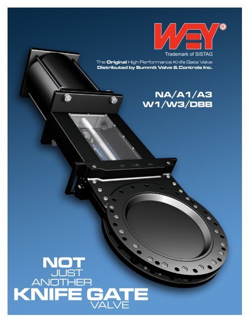
Trademark of SISTAG<br />
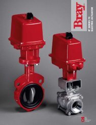
The Original High Performance Knife Gate <strong>Valve</strong><br />
Distributed by <strong>Summit</strong> <strong>Valve</strong> & <strong>Controls</strong> Inc.<br />
NA/A1/A3<br />
W1/W3/DBB<br />
C<br />
A<br />
B<br />
NOT<br />
JUST<br />
ANOTHER<br />
<strong>KNIFE</strong> <strong>GATE</strong><br />
VALVE
COMPARE THESE UNIQUE FEATURES<br />
1 Totally enclosed<br />
heavy-duty bonnet<br />
2 Lexan window for<br />
position indication<br />
3 Non-rising stem<br />
(manual actuation -<br />
NA model only)<br />
4 Proximity switches<br />
5 Lifting lugs<br />
6 TFE packing (repackable<br />
while in<br />
service <strong>and</strong> under<br />
pressure) SEE<br />
ILLUSTRATION A<br />
7 Heavy-duty body<br />
design conforming<br />
to MSS SP-135, MSS<br />
SP-81 or customer<br />
specified face to face<br />
dimensions<br />
8 Reduced chest cavity<br />
(prevents jamming)<br />
9 Type 17.4-PH stainless<br />
steel gate<br />
10 ANSI 150 or 300 flange<br />
bolt pattern<br />
11 Replaceable ni-hard<br />
wear ring<br />
12 XYGOO-II coated body<br />
& gate<br />
13 Lock-out pins<br />
14 H<strong>and</strong>wheel, manual<br />
bevel gear, hydraulic,<br />
pneumatic or electric<br />
actuators<br />
15 Self flushing<br />
contoured body bore<br />
16 Dual heavy-duty<br />
top transverse seal<br />
with upper & lower<br />
scraper blades (low<br />
temperature viton<br />
seal material) (SEE<br />
ILLUSTRATION B)<br />
17 Gate guided for full<br />
length of stroke for<br />
bi-directional bubbletight<br />
shut-off (SEE<br />
ILLUSTRATION C)<br />
18 Solenoid valves or<br />
positioners (NOT<br />
SHOWN)<br />
14<br />
A<br />
1<br />
2<br />
Section of transverse seal illustrating how sealing compound is<br />
inserted into chamber to repack valve while valve is in service.<br />
3<br />
B<br />
Resilient<br />
transverse seal<br />
Various elastomeric seal<br />
materials available. Seal<br />
includes compression<br />
loaded scraper blades<br />
to wipe gate clean <strong>and</strong><br />
protect seal. Repackable<br />
in service <strong>and</strong> under<br />
pressure/vacuum.<br />
4<br />
5<br />
6<br />
7<br />
8<br />
13<br />
12<br />
(Dual scraper shown)<br />
C<br />
Section view:<br />
D<br />
Ni-hard<br />
wear ring<br />
9<br />
10<br />
11<br />
Section view:<br />
Mechanically retained<br />
resilient seal insures bubbletight<br />
shutoff with pressure<br />
on either side of gate. Seal<br />
will not pull out of specially<br />
machined groove.<br />
visit us online at www.weyvalve.com
BODY STYLES<br />
OPTIONAL DBB CONFIGURATION<br />
Model NA: 2” to 36”, ANSI 150 flanges<br />
MSS SP-81-2006a face-to-face dimensions.<br />
Model A1: 2” to 42”, ANSI 150 flanges<br />
Model A3: 3” to 42”, ANSI 300 flanges<br />
WEY face-to-face dimensions.<br />
Model DBB-D1: ANSI 150 flanges<br />
Model DBB-D3: ANSI 300 flanges<br />
WEY face-to-face dimensions.<br />
Model W1: 3” to 42”, ANSI 150 flanges<br />
Model W3: 3” to 42”, ANSI 300 flanges<br />
MSS SP-135-2006 face-to-face dimensions.<br />
Raised or flat face flanges are available. Threaded flange<br />
bolt holes are st<strong>and</strong>ard. Drill through flange bolt holes<br />
are optional.<br />
The unique WEY model DBB<br />
serves as both a Double Block<br />
& Bleed valve <strong>and</strong> a line blind.<br />
This unique design has two<br />
gates operated by one actuator.<br />
The WEY Model DBB reduces<br />
the number of valves required<br />
for a traditional double block<br />
& bleed application. Reducing<br />
the number of valves required<br />
eliminates additional leak<br />
paths due to multiple flange<br />
connections <strong>and</strong> costs<br />
associated with extra valves<br />
<strong>and</strong> piping requirements.<br />
The unique features of the<br />
st<strong>and</strong>ard single gate model are<br />
incorporated in the DBB valve.<br />
Two gates<br />
Three center<br />
section ports<br />
VALVE SIZING<br />
VALVE<br />
SIZE<br />
O-PORT<br />
(Cv)<br />
HEADLOSS<br />
(Ft. of pipe)<br />
V-PORT<br />
(Cv)<br />
HEADLOSS<br />
(Ft. of pipe)<br />
2” 220 2.2 185 3.7<br />
2.5” 350 2.7 295 4.8<br />
3” 500 3.3 425 6.0<br />
4” 960 4.3 750 8.1<br />
6” 2,220 6.5 1,680 14.1<br />
8” 4,120 8.7 3,000 20.0<br />
10” 6,600 10.8 4,700 24.0<br />
12” 9,700 13.0 6,800 30.0<br />
14” 14,200 15 9,250 32.0<br />
16” 18,800 17.0 12,000 35.0<br />
18” 24,200 19.5 15,200 38.0<br />
20” 30,200 22.0 18,750 42.0<br />
24” 43,500 26.0 27,250 54.0<br />
30” 69,000 33.0 42,500 70.0<br />
36” 101,000 39.0 61,000 88.0<br />
42” 139,000 52.0 82,500 117.0<br />
Cv = Flow coefficient = Flow through valve in<br />
USGPM at a 1 PSI pressure differential<br />
THREE METHODS OF PROTECTION<br />
1.<br />
2.<br />
3.<br />
Vent center section to atmosphere.<br />
Connect center section to flush or purge.<br />
Pressurize center section to pressure<br />
higher than either side of the valve.<br />
Note: leak detector (“sniffer”) can be used with<br />
any of the three protection options.<br />
port #1 port #2<br />
port #3<br />
OSHA “crabclaw”<br />
lock-out device<br />
Two gates<br />
Three center<br />
section ports<br />
ASME/ANSI CLASS RATINGS<br />
SIZE BODY CLASS<br />
2” to 36” NA 125/150<br />
3” to 42” A1 125/150<br />
3” to 42” A3 250/300<br />
2” to 36” W1 150<br />
2” to 36” W3 300<br />
2” to 36” DBB-D1 150<br />
2” to 36” DBB-D3 300<br />
BODY PRESSURE RATINGS<br />
BODY RATING<br />
Class 125/250<br />
Class 150/300<br />
MATERIALS OF CONSTRUCTION<br />
Cast iron & cast ni-resist (ASME/ANSI B16.1)<br />
Ductile iron & ductile ni-resist<br />
(ASME/ANSI B16.42)<br />
Carbon steel & steel alloys (ASME/ANSI B16.34)<br />
TEMPERATURE: The operating temperature must not exceed the elastomer maximum<br />
temperature rating.<br />
(for example: Nitrile/Buna N = 180° F, EPDM = 250° F, FKM/Viton = 400° F, Aflas= 500°F)<br />
Not Just Another Knife Gate <strong>Valve</strong>
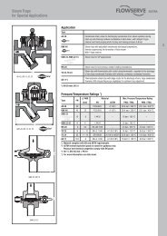
DIMENSIONS<br />
WEY-OSKG-2010-08<br />
K<br />
F<br />
B2<br />
CYLINDER BEVEL GEAR HAND WHEEL<br />
DBB***<br />
J =This dimension varies with cylinder size. Please consult your sales representative for recommended cylinder size.<br />
Flange bolting: Quantity, bolt circle diameters, flange bolt threads are as per ASME B16.5 Class 150 <strong>and</strong> 300 (NPS less than or equal to 24”), <strong>and</strong><br />
ASME B16.47 Series A Class 150 <strong>and</strong> 300 (NPS greater than 24”). Optional drill through flange bolt holes are available.<br />
Consult Wey for depth <strong>and</strong> number of blind tapped holes in chest area of valve.<br />
G<br />
VALVE SIZE<br />
A<br />
MSS<br />
SP-81<br />
B<br />
Single gate design<br />
Wey st<strong>and</strong>ard<br />
face to face<br />
MSS SP-135<br />
IN. MM NA A1 A3 W1 W3<br />
B2<br />
Double block & bleed<br />
DBB<br />
D1<br />
DBB<br />
D3<br />
NA/<br />
A1/<br />
W1<br />
D E F G H I K<br />
2” 50 2.00 1.88 2.38 - 2.75 2.75 3.60 - 13.5 - - - 10 7.38 - - -<br />
3” 80 3.13 2.00 2.75 2.75 4.00 4.00 3.22 4.28 16.5 21.5 - 21.5 13.5 7.38 12 - .38<br />
4” 100 4.00 2.00 2.75 2.75 4.12 4.12 3.42 4.28 20 24 - 24 15.5 7.38 12 - .38<br />
6” 150 6.00 2.25 3.25 3.15 2.50 4.12 3.94 4.92 25.5 30 - 28 20 9.88 12 - .50<br />
8” 200 7.88 2.75 3.54 3.54 2.88 4.63 4.34 5.55 34 35.5 - 32 24 11.81 12 - .50<br />
10” 250 9.88 2.75 3.94 3.94 3.12 5.38 4.88 6.21 38.5 42 - 35 26 11.81 12 - .50<br />
12” 300 11.88 3.00 4.33 4.33 3.25 5.63 5.17 6.85 48 53 - 44.5 31 15.75 18 - .50<br />
14” 350 13.88 3.00 4.72 4.72 3.62 6.25 5.68 7.55 52.5 56 43.5 46.5 34 15.75 18 13.25 .50<br />
16” 400 15.75 3.50 4.72 4.72 3.75 6.63 6.18 7.55 58 61 48.5 52 39 15.75 18 13.25 .50<br />
18” 450 17.75 3.50 5.51 5.51 4.12 7.00 8.37 8.82 66 68 52.5 55.5 43 19.75 18 13.25 .50<br />
20” 500 19.75 4.50 5.90 5.90 4.50 7.38 8.80 9.48 75.5 79 56 62 46.5 19.75 24 14.75 .50<br />
24” 600 23.63 4.50 6.69 6.69 5.00 8.38 9.76 10.82 85.5 89 66 71.5 56.5 19.75 24 14.75 .50<br />
26” 650 25.63 - 7.08 7.08 6.75 8.50 11.26 11.53 96.75 97 - - - - - - .50<br />
28” 700 27.56 - 7.48 7.48 7.12 10.00 11.69 12.11 100.5 102 - - - - - - .50<br />
30” 750 30.00 4.62 8.26 8.26 7.38 10.50 13.03 13.38 102.5 107 - - - - - - .50<br />
32” 800 - - - - 8.12 11.50 - - 102.5 107 - - - - - - .50<br />
36” 900 35.44 4.62 9.84 9.84 8.88 12.00 - - 112.5 133 - - - - - - .50<br />
42” 1050 41.34 - 11.00 13.78 - - - - 142 160 - - - - - - .50<br />
A3/<br />
W3<br />
NA/<br />
A1/<br />
W1<br />
A3/<br />
W3**<br />
NA/<br />
A1/<br />
W1<br />
J<br />
H<br />
I<br />
Vent<br />
Port<br />
Size<br />
(NPT)<br />
D<br />
E<br />
Consult factory for valve sizes 48”-96” dimensions. Dimensions shown in inches<br />
* NA model conforms to TAPPI <strong>and</strong> MSS SP81 face-to-face st<strong>and</strong>ards in sizes 2” to 24”.<br />
** Manual A3 models have a rising stem, the dimensions shown account for the stem at it’s highest point.<br />
*** All dimensions for the DBB valve are identical to the st<strong>and</strong>ard valve except for B2 <strong>and</strong> K.<br />
Important note: All dimensions subject to change, consult factory for certified dimensions.<br />
DISTRIBUTED BY:<br />
<strong>Summit</strong> <strong>Valve</strong> <strong>and</strong> <strong>Controls</strong> Inc.<br />
5304-68 Avenue<br />
Edmonton, Alberta<br />
T6B 3M4<br />
Phone: 780-468-6900<br />
Fax: 780-468-1400<br />
www.summitvalve.com<br />
VALVE, INC.<br />
A member of SISTAG Group<br />
P.O. Box 387<br />
Nettleton, MS 38858 USA<br />
Phone: 662-963-2020<br />
Fax: 662-963-2025<br />
Visit our web site @ www.weyvalve.com
TOP 10<br />
REASONS TO<br />
10 REASONS TO CHOOSE WEY VALVE<br />
CHOOSE<br />
VALVE<br />
1<br />
<br />
<br />
50 Years Proven High Performance Design<br />
<br />
<br />
Worldwide Service<br />
All<br />
Industries<br />
<br />
<br />
Sizes 2" to 96"<br />
All<br />
Materials Available<br />
Pressures to 1440 PSI<br />
Ordinary Knife Gate Design Ordinary Knife Gate Design Problem Problem<br />
Leakage<br />
Leakage<br />
Leakage<br />
Leakage<br />
Extended<br />
Extended<br />
Extended<br />
Chest<br />
Extended<br />
Chest<br />
Chest<br />
Chest<br />
180º<br />
180º<br />
180º<br />
180º<br />
Arc<br />
Arc<br />
Leakage<br />
Leakage<br />
Leakage<br />
Leakage<br />
Large<br />
Cavities<br />
Large<br />
Gate Closing<br />
Large Gate Closing<br />
In<br />
Cavities Large Gate Closing<br />
Body<br />
Cavities Gate Closing<br />
In Cavities<br />
In<br />
Body<br />
Body<br />
In Body<br />
Force<br />
Moments<br />
Force<br />
Force<br />
Moments<br />
Force<br />
Moments<br />
Moments<br />
2<br />
Tightest Shut-off in<br />
the Industry<br />
Bi-Directional Zero<br />
cc/min from 28"<br />
HG Vac to Full<br />
Pressure Rating<br />
(In-Line <strong>and</strong> to<br />
Atmosphere)<br />
EXCEEDS EXCEEDS ANSI<br />
CLASS VI ANSI<br />
CLASS VI SHUT-OFF<br />
SHUT-OFF<br />
SOLUTION: SOLUTION: Wey Wey <strong>Valve</strong>’s <strong>Valve</strong>’s Unique Unique Self-Cleaning<br />
Self-Cleaning<br />
Design Design<br />
5 Reduced Chest Maximum 60º Arc on Gate<br />
6 Tight Tolerance<br />
Wedging<br />
Wedging<br />
Wedging<br />
Wedging<br />
Max 60º Arc<br />
Max<br />
Max 60º<br />
60º Arc<br />
Arc<br />
Max 60º Arc<br />
Max 60º Arc<br />
3<br />
TRANSVERSE TRANSVERSE SEAL<br />
SEAL<br />
Re-Packable under Pressure<br />
7<br />
Gate Guided for Full<br />
Length of Stroke<br />
Pushes Media Downward<br />
Pushes<br />
Pushes Media through Media Downward<br />
Gate Downward<br />
Guides<br />
Pushes through<br />
through Media Gate<br />
Gate Downward Guides<br />
Guides<br />
Pushes through Media Gate Downward Guides<br />
through Gate Guides<br />
4<br />
TRANSVERSE TRANSVERSE SEAL<br />
SEAL<br />
Both Sides of Gate<br />
TRANSVERSE TRANSVERSE SEAL<br />
SEAL<br />
Compensates For Wear<br />
SEAL<br />
SEAL<br />
PACKING SEAL<br />
PACKING SEAL<br />
PACKING<br />
PACKING<br />
BARRIER STRIP<br />
BARRIER SCRAPER<br />
BARRIER<br />
STRIP<br />
STRIP<br />
BLADE<br />
SCRAPER<br />
BARRIER STRIP<br />
COMPRESSION<br />
BLADE SCRAPER<br />
O-RING<br />
BLADE SCRAPER<br />
COMPRESSION<br />
BLADE<br />
O-RING COMPRESSION<br />
O-RING COMPRESSION<br />
O-RING<br />
<strong>GATE</strong><br />
<strong>GATE</strong><br />
<strong>GATE</strong><br />
<strong>GATE</strong><br />
8<br />
9<br />
10<br />
Contoured Bore Promotes Self-Cleaning<br />
Solids pushed ahead of gate are flushed<br />
out as velocity increases <strong>and</strong> gate tip<br />
moves into open relief areas in lower<br />
bore. Seat is flush fitted with bottom<br />
of bore leaving no place for solids to pack.<br />
No Flush Ports Required!<br />
Absolute Shut-off Guarantee!