SENTRY-PRO POWER SYSTEMS By Gillette Generators, Inc.
SENTRY-PRO POWER SYSTEMS By Gillette Generators, Inc.
SENTRY-PRO POWER SYSTEMS By Gillette Generators, Inc.

Create successful ePaper yourself
Turn your PDF publications into a flip-book with our unique Google optimized e-Paper software.
<strong>SENTRY</strong>-<strong>PRO</strong> <strong>POWER</strong> <strong>SYSTEMS</strong><br />
<strong>By</strong> <strong>Gillette</strong> <strong>Generators</strong>, <strong>Inc</strong>.<br />
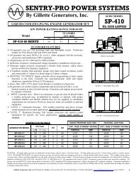
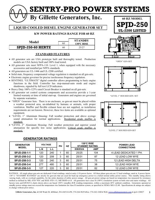
LIQUID COOLED DIESEL ENGINE GENERATOR SET<br />
KW <strong>POWER</strong> RATINGS RANGE FOR 60 HZ<br />
STANDARD FEATURES<br />
STANDBY<br />
130ºC RISE<br />
Model<br />
HZ<br />
SPJD-250-60 HERTZ 60 25/27<br />
60 HZ MODEL<br />
SPJD-250<br />
UL-2200 LISTED<br />
• All generator sets are USA prototype built and thoroughly tested. Production<br />
models are USA factory built and 100% load tested.<br />
• All generator sets meet NFPA-110. Level 1, when equipped with the necessary<br />
accessories and installed per NFPA standards.<br />
• All generators are UL-1446 and UL-2200 certified.<br />
• Solid state, frequency compensated voltage regulation is standard on all gen-sets.<br />
• Electronic engine governor for precise isochronous frequency regulation.<br />
• SENTINEL “ULTIMATE” digital controller allows programming to basic engine<br />
functions in the field. Controller has stop-manual-auto mode and engine<br />
shutdowns, signaled by full text LCD indicators.<br />
• Heavy Duty 100%-125% rated Circuit Breaker is standard on all gen-sets.<br />
• All generator set control systems components and accessories provide a 1-year<br />
limited warranty at time of initial start-up. <strong>Generators</strong> and engines are governed<br />
by separate warranties.<br />
• “OPEN” Generator Sets: There is no enclosure, so gen-set must be placed within<br />
a weather protected area, un-inhabited by humans or animals, with proper<br />
ventilation. Muffler and flexible exhaust hose are not supplied, as installation<br />
requirements are not known. However, these two items are available as optional<br />
equipment.<br />
• “LEVEL 1” Aluminum Housing: Full weather protection and above average<br />
sound attenuation for normal applications. Residential grade muffler is<br />
standard.<br />
• “LEVEL 2” Aluminum Housing: Full weather protection and superior sound<br />
attenuation for specific low noise applications. Critical grade muffler is<br />
standard.<br />
“OPEN” GEN-SET<br />
“LEVEL 1” HOUSED GEN- SET<br />
“LEVEL 2” HOUSED GEN-SET<br />
GENERATOR RATINGS<br />
130°C RISE<br />
GENERATOR<br />
VOLTAGE<br />
<strong>POWER</strong> LEAD<br />
PH HZ STANDBY RATING<br />
MODEL<br />
CONNECTIONS<br />
L-N L-L<br />
KW/KVA AMP<br />
SPJD-250-1-1 120 240 1 60 25/25 104 4 LEAD DEDICATED 1 PH.<br />
SPJD-250-3-2 120 208 3 60 25/31 87 12 LEAD LOW WYE<br />
SPJD-250-3-3 120 240 3 60 25/31 75 12 LEAD HIGH DELTA<br />
SPJD-250-3-4 277 480 3 60 25/31 38 12 LEAD HIGH WYE<br />
SPJD-250-3-5 127 220 3 60 25/31 82 12 LEAD LOW WYE<br />
RATINGS: All single phase gen-sets are dedicated 4 lead windings, rated at unity (1.0) power factor. All three phase gen-sets are 12 lead windings, rated at .8 power factor.<br />
130° C “STANDBY RATINGS” are strictly for gen-sets that are used for back-up emergency power to a failed normal utility power source. This standby rating allows<br />
varying loads, with no overload capability, for the entire duration of utility power outage. All gen-set power ratings are based on temperature rise measured by resistance<br />
method as defined by MIL-STD 705C and IEEE STD 115, METHOD 6.4.4. All generators have class H (180°C) insulation system on both rotor and stator windings. All<br />
factory tests and KW/KVA charts shown above are based 130°C (standby) R/R winding temperature, within a maximum 40°C ambient condition. <strong>Generators</strong> operated at<br />
standby power ratings must not exceed the temperature rise limitation for class H insulation system, as specified in NEMA MG1-22.40. Specifications & ratings are subject<br />
to change without prior notice.<br />
<strong>Gillette</strong> <strong>Generators</strong>, <strong>Inc</strong>. •1340 Wade Dr. •Elkhart, IN • 46514 • Ph: 574-264-9639 •Fax: 574-262-1840 • Web: www.gillettegenerators.com • spc4-120827 1
APPLICATION AND ENGINEERING DATA FOR MODEL SPJD-250-60 HZ<br />
GENERATOR SPECIFICATIONS<br />
GENERATOR FEATURES<br />
Manufacturer.................................. Marathon Electric <strong>Generators</strong><br />
Model & Type............ 283PSL1517 4 Pole, 4 Lead, Single Phase<br />
......... 283CSL1706 4 Pole, 12 Lead re-connectable, Three Phase<br />
Exciter.....................................................Brushless, shunt excited<br />
Voltage Regulator .......................................Solid State, HZ/Volts<br />
Voltage Regulation ................................½%, No load to full load<br />
Frequency................................Field convertible, 60 HZ to 50 HZ<br />
Frequency Regulation ......... ± ½% (½ cycle, no load to full load)<br />
Unbalanced Load Capability.....................100% of standby amps<br />
Total Stator and Load Insulation...........................Class H, 180°C<br />
Temperature Rise ......... 130°C R/R, standby rating @ 40°C amb.<br />
1 Ø Motor Starting @ 30% Voltage Dip (240V) ..............60 kVA<br />
3 Ø Motor Starting @ 30% Voltage Dip (208-240V).......55 kVA<br />
3 Ø Motor Starting @ 30% Voltage Dip (480V) ..............75 kVA<br />
Bearing..................................................... 1, Pre-lubed and sealed<br />
Coupling.........................................................Direct flexible disc.<br />
Total Harmonic Distortion............... Max 3½% (MIL-STD705B)<br />
Telephone Interference Factor ............Max 50 (NEMA MG1-22)<br />
Deviation Factor................................. Max 5% (MIL-STD 405B)<br />
Ltd. Warranty Period.............. 24 Months from date of start-up or<br />
.......................................................1000 hours use, first to occur.<br />
• World Renown Marathon Electric Generator having UL-1446<br />
certification.<br />
• Full generator protection with SENTINEL “ULTIMATE”<br />
controller, having UL-508 certification.<br />
• Automatic voltage regulator with over-excitation, underfrequency<br />
compensation, under-speed protection, and EMI<br />
filtering. Entire solid-state board is encapsulated for<br />
moisture protection.<br />
• Generator power ratings are based on temperature rise,<br />
measured by resistance method, as defined in MIL-STD<br />
705C and IEEE STD 115, Method 6.4.4.<br />
• Power ratings will not exceed temperature rise limitation for<br />
class H insulation as per NEMA MG1-22.40.<br />
• Insulation resistance to ground, exceeds 1.5 meg-ohm.<br />
• Stator receives 2000 V. hi-potential test on main windings,<br />
and rotor windings receive a 1500 V. hi-potential test, as per<br />
MIL-STD 705B.<br />
• Full amortisseur windings with UL-1446 certification.<br />
• Complete engine-generator torsional acceptance, confirmed<br />
during initial prototype testing.<br />
• Full load testing on all engine-generator sets, before shipping.<br />
• Self ventilating and drip-proof & revolving field design<br />
ENGINE SPECIFICATIONS AND APPLICATIONS DATA<br />
ENGINE___________________________________<br />
Manufacturer............................................................... John Deere<br />
Model and Type ............................................ 4024TF281, 4 cycle<br />
Aspiration................................................................Turbocharged<br />
Cylinder Arrangement......................4 Cylinders, In-Line, 4 cycle<br />
Displacement Cu. In. (Liters)..........................................149 (2.4)<br />
Bore & Stroke In. (Cm.)...............................3.4 x 4.1 (8.6 x 10.5)<br />
Compression Ratio.............................................................. 20.5:1<br />
Main Bearings & Style............................ 4, Cu-Pb Metal, Babbitt<br />
Cylinder Head .................................................................Cast Iron<br />
Pistons.................................................4, Aluminum Wedge Type<br />
Crankshaft..................................... Carbon Steel & Full Balanced<br />
Exhaust Valve ............................................... Heat Resisting Steel<br />
Governor .......................................................................Electronic<br />
Frequency Regulation ................................ ±1/4% Isochronous<br />
Air Cleaner.........................................Dry, Replaceable Cartridge<br />
Engine Speed ................................................ ................1800 rpm<br />
Max Power, bhp (kwm) Standby ................... ................. 48 (36)<br />
BMEP: psi (kpa) Standby ............................. ................142 (981)<br />
Ltd. Warranty Period……..24 months or 1000 hrs, first to occur<br />
FUEL SYSTEM ____________________________<br />
Type ......................................... Diesel Fuel Oil (ASTM No. 2-D)<br />
Combustion System ............................................. Direct Injection<br />
Fuel Injection Pump.................................Stanadyne Rotory Type<br />
12 VDC Glo-Plugs........................................Standard Equipment<br />
Fuel Filter and Water Separator……………………………...Yes<br />
FUEL CONSUMPTION<br />
GAL/HR (LITER/HR)<br />
STANDBY<br />
100% LOAD 2.2 (8.3)<br />
75% LOAD 1.7 (6.4)<br />
50% LOAD 1.1 (4.2)<br />
OIL SYSTEM<br />
Type ......................................................................... Full Pressure<br />
Oil Pan Capacity qt. (L) ...................................................8.5 (8.0)<br />
Oil Pan Cap. W/ filter qt. (L) ...........................................9.0 (8.5)<br />
Oil Filter................................. 1, Replaceable Spin-On<br />
ELECTRICAL SYSTEM _____________________<br />
Ignition System .............................................................Electronic<br />
Eng. Alternator and Starter:<br />
Ground .....................................................................Negative<br />
Volts DC ............................................................................ 12<br />
Max. Amp Output of Alternator......................................... 55<br />
Recommended Battery to -18°C (0°F):.. 12 VDC, Size BCI# 24F<br />
Max Dimensions: ..10 3/4" lg X 6 3/4” wi X 9" hi, with standard<br />
round posts. Min. output at 600 CCA. Battery tray (max. dim.<br />
at 12”lg x 7”wi), hold down straps, battery cables, and battery<br />
charger, is furnished. Installation of (1) starting battery is<br />
required, with possible higher AMP/HR rating, as described<br />
above, if normal environment averages -13°F (-25°C) or cooler.<br />
CERTIFICATIONS<br />
All engines are CARB and EPA emissions certified. All<br />
stationary diesel engines are Interim Tier IV compliant.<br />
2<br />
<strong>Gillette</strong> <strong>Generators</strong>, <strong>Inc</strong>. •1340 Wade Dr. •Elkhart, IN • 46514 • Ph: 574-264-9639 •Fax: 574-262-1840 • Web: www.gillettegenerators.com • spc4-120827
APPLICATION AND ENGINEERING DATA FOR MODEL SPJD-250-60 HZ<br />
COOLING SYSTEM<br />
Type of System ................................ Pressurized, closed recovery<br />
Coolant Pump .....................................Pre-lubricated, self-sealing<br />
Cooling Fan Type (no. of blades) .................................Pusher (6)<br />
Fan Diameter inches (cm)................................................ 18" (46)<br />
Ambient Capacity of Radiator °F (°C).............................125 (52)<br />
Engine Jacket Coolant Capacity Qt. (L) ..........................2.7 (2.6)<br />
Radiator Coolant Capacity Qt. (L)...............................6.46 (6.12)<br />
Engine Heat Reject. Btu/min (kw) ……………………1412 (25)<br />
Water Pump Capacity gpm (L/min).............. .................. 24 (91)<br />
Heat Reject Coolant: Btu/min (kw) …. ........ ................1412 (25)<br />
Low Radiator Coolant Level Shutdown………………...Standard<br />
Note: Coolant temp. Shutdown switch setting at 212°F (100°C) with 50/50<br />
(water/antifreeze) mix.<br />
COOLING AIR REQUIREMENTS<br />
Combustion Air cfm (m 3 /min) ...................... .................123 (3.5)<br />
Max. Air Intake Restrictions :<br />
Clean Air Cleaner, H 2 O (KPA).............. ................... 12 (3)<br />
Intake Manifold Pressure, Psi (kpa) ............. .................. 11 (75)<br />
Max. Allowable Temp. Rise, Amb:<br />
Air to Engine Inlet, °F (°C) ................... ................... 15 (8)<br />
Radiator Cooling Air, SCFM (m 3 /min) ........ ................3200 (91)<br />
EXHAUST SYSTEM<br />
Exhaust Outlet Size....................................................................2"<br />
Max. Back Pressure in H 2 O (kpa).....................................30 (7.5)<br />
Exhaust Flow, at rated KW, cfm (m 3 /min) ... .................283 (8.0)<br />
Exhaust Temp, at rated KW,°F (ºC).............. ..............1026 (552)<br />
SOUND LEVELS MEASURED IN dB(A)<br />
Open Level 1 Level 2<br />
Set Encl.. Encl.<br />
Level 1, Residential Silencer....................71..........67 .........n/a<br />
Level 2, Critical Silencer .........................68..........64 ......... 62<br />
Level 3, Hospital Silencer........................66..........62 ......... 60<br />
Note: Open sets (no enclosure) has (3) optional silencer system choices<br />
due to unknown job-site applications. Level 1 enclosure has installed<br />
residential silencer with upgrade to critical or hospital grade silencer.<br />
Level 2 enclosure has installed critical silencer with upgrade to hospital<br />
silencer. Sound tests are averaged from several test points and taken at<br />
23 ft. (7 m) from source of noise at normal operation.<br />
DERATE GENERATOR FOR ALTITUDE<br />
3% per 1000 ft.(305m) above 3000 ft. (914m) from sea level<br />
DERATE GENERATOR FOR TEMPERATURE<br />
2% per 10°F (5.6°C) above 85°F (29.4°C)<br />
DIMENSIONS AND WEIGHTS<br />
Open Level 1 Level 2<br />
Set Enclosure Enclosure<br />
Length in (cm)...................68 (173)....... 82 (208) .......... 89 (226)<br />
Width in (cm)................... 36 (91) ...... 36 (91) .......... 36 (91)<br />
Height in (cm).................. 40 (102)...... 47 (119).......... 47 (119)<br />
1 Ø Net Weight lbs (kg)..1244 (564)... 1599 (725) .....1779 (807)<br />
1 Ø Ship Weight lbs (kg) 1344 (610)... 1709 (775) .....1880 (853)<br />
3 Ø Net Weight lbs (kg)..1294 (587)... 1574 (714) .....1754 (796)<br />
3 Ø Ship Weight lbs (kg) 1399 (635)... 1682 (763) .....1848 (838)<br />
SENTINEL ULTIMATE DIGITAL MICRO<strong>PRO</strong>CESSOR CONTROLLER<br />
SENTINEL ULTIMATE<br />
The “Ultimate” controller<br />
is an auto start mains<br />
(utility) failure module for<br />
single gen-set applications.<br />
This controller includes a<br />
backlit LCD display which<br />
continuously displays the<br />
status of the engine and<br />
generator at all times.<br />
The “Ultimate” controller will also monitor speed, frequency,<br />
voltage, current, oil pressure, coolant temp., and fuel levels.<br />
These modules have been designed to display warning and shut<br />
down status. It also includes: (11) configurable inputs • (8)<br />
configurable outputs • voltage monitoring • mains (utility)<br />
failure detection • (250) event logs • configurable timers •<br />
automatic shutdown or warning during fault detection • remote<br />
start (on load) • engine preheat • advanced metering capability •<br />
hour meter • text LCD displays • protected solid state outputs •<br />
test buttons for: stop/reset • manual mode • auto mode • lamp<br />
test • start button • power monitoring (kWh, kVAr, kVAh,<br />
kVArh)<br />
This controller includes the “Ultimate” in expansion features<br />
including RS232, RS484 (using MODBUS-RTU/TCP), direct<br />
USB connection with PC, expansion optioned using DSENet for<br />
remote annunciation and remote relay interfacing for a distance<br />
of up to 3300FT. The controller software is freely downloadable<br />
from the internet and allows monitoring with direct USB cable,<br />
LAN, or by internet via the built in web interface.<br />
Further expansion is available by<br />
adding the optional “WebNet“ gateway<br />
interface module. This device will allow<br />
comprehensive monitoring of the generator<br />
via the cloud including identification,<br />
location, and status. Some advantages of this<br />
module include: reduced site visits and<br />
maintenance costs • remote fuel management<br />
• fault analysis • asset tracking • automatic<br />
system alerts • maximized system up-time.<br />
<strong>Gillette</strong> <strong>Generators</strong>, <strong>Inc</strong>. •1340 Wade Dr. •Elkhart, IN • 46514 • Ph: 574-264-9639 •Fax: 574-262-1840 • Web: www.gillettegenerators.com • spc4-120827 3
STANDARD AND OPTIONAL FEATURES FOR MODEL SPJD-250-60 HZ<br />
CONTROL PANEL:<br />
SENTINEL “ULTIMATE” digital microprocessor with<br />
logic allows programming in the field. Controller has:<br />
• STOP-MANUAL-AUTO modes and automatic engine<br />
shutdowns, signaled by full text LCD indicators:<br />
• Low oil pressure • Engine fail to start<br />
• High engine temp • Engine over speed<br />
• Low Radiator Level • Engine under speed<br />
• Three auxiliary alarms • Over & under voltage<br />
• Battery fail alarm<br />
Also included is tamper-proof engine hour meter<br />
ENGINE:<br />
Full flow oil filter • Air filter • Oil pump • Solenoid type<br />
starter motor • Hi-temp radiator • Jacket water pump<br />
• Thermostat • Pusher fan and guard • Exhaust manifold<br />
• Residential Silencer • 12 VDC battery charging alternator<br />
• Flexible exhaust connector • ”Isochronous” duty,<br />
electronic governor • Vibration isolators • Closed coolant<br />
recovery system with 50/50 water to anti-freeze mixture<br />
STANDARD FEATURES<br />
ACCESSORY ITEMS<br />
AC GENERATOR SYSTEM:<br />
AC generator • Shunt excited • Brushless design • Circuit<br />
Breaker installed and wired to gen-set • Direct connection<br />
to engine with flex disc • Class H, 180°C insulation • Self<br />
ventilated • Drip proof construction • UL Certified<br />
VOLTAGE REGULATOR:<br />
½% Voltage regulation • EMI filter • Under-speed<br />
protection • Over-excitation protection • total encapsulation<br />
DC ELECTRICAL SYSTEM:<br />
Battery tray • Battery cables • Battery hold down straps<br />
• 2-stage battery float charger with maintaining &<br />
recharging automatic charge stages.<br />
WEATHER/SOUND <strong>PRO</strong>OF ALUMINUM HOUSING<br />
CORROSION RESISTANT <strong>PRO</strong>TECTION CONSISTING OF:<br />
• 9 Heated And Agitated Wash Stages.<br />
• Zinc Phosphate Etching-coating Stage<br />
• Final Baked On Enamel Powder Coat<br />
• 18/8 Stainless Steel Hardware<br />
Engine Coolant Heater with automatic 80°F on, 100°F<br />
off, thermostat<br />
Starting Battery Heater Blanket with automatic 60°F<br />
on, 80°F off, thermostat<br />
Battery Charger Upgrade, float type, 12 VDC at max.<br />
charge, with ammeter on charger.<br />
External Permanent Magnet Generator (PMG) for<br />
increased induction motor starting capacity on 1∅ or<br />
3 ∅ sets, and to meet NFPA-110 requirements.<br />
Exhaust Silencer Critical Grade or Hospital Grade<br />
(Replacing standard Residential Grade).<br />
<br />
<br />
<br />
All brushed type 304 stainless steel weather and sound<br />
deadening housing for coastal areas.<br />
DSE WebNet Gateway expansion module will allow<br />
communications with a host server via Ethernet and the<br />
DSE cloud connection for mapping static locations, real<br />
time instrumentation, control event log tables, and<br />
automatic system alerts via email.<br />
Remote Annunciator for up to (10) reporting functions.<br />
An additional relay expansion module, plus a second<br />
Annunciator adds another (10) reporting functions.<br />
Design & specifications subject to change<br />
without prior notice. Dimensions shown are<br />
approximate. Contact <strong>Gillette</strong> for certified<br />
drawings. DO NOT USE DIMENSIONS FOR<br />
INSTALLATION PURPOSES.<br />
4<br />
<strong>Gillette</strong> <strong>Generators</strong>, <strong>Inc</strong>. •1340 Wade Dr. •Elkhart, IN • 46514 • Ph: 574-264-9639 •Fax: 574-262-1840 • Web: www.gillettegenerators.com • spc4-120827
Rating:<br />
Application:<br />
ENGINE PERFORMANCE CURVE<br />
Gross Power<br />
Generator<br />
1800 RPM (60 Hz)<br />
PowerTech E TM 2.4L Engine<br />
Model: 4024TF281<br />
43 hp (32 kW) Prime<br />
49 hp (36 kW) Standby<br />
Generator<br />
Efficiency 1<br />
%<br />
Nominal Engine Power @ 1800 RPM<br />
Prime<br />
Standby<br />
HP kW HP kW<br />
43 32 49 36<br />
Fan Power<br />
Power<br />
Factor<br />
Prime Rating<br />
Standby<br />
Rating 2<br />
4 sec Standby<br />
Block Load<br />
Capability 3<br />
hp kW kWe kVA kWe kVA<br />
88 2.4 1.8 0.8 27 34 30 38 100%<br />
Note 1: Est. min. generator efficiency, with 5% fan power loss, to achieve Prime kVA (1500 rpm) / Standby kWe (1800 rpm).<br />
Note 2: Based on nominal engine power.<br />
Note 3: Results may vary by alternator and voltage regulator selection.<br />
Air Intake Restriction ...................12 in.H 2 O (3 kPa)<br />
Exhaust Back Pressure ........... 30 in.H 2 O (7.5 kPa)<br />
Gross power guaranteed within + or - 5% at SAE J1995<br />
and ISO 3046 conditions:<br />
77 °F (25 °C) air inlet temperature<br />
29.31 in.Hg (99 kPa) barometer<br />
104 °F (40 °C) fuel inlet temperature<br />
0.853 fuel specific gravity @ 60 °F (15.5 °C)<br />
Conversion factors:<br />
Power: kW = hp x 0.746<br />
Fuel: 1 gal = 7.1 lb, 1 L = 0.85 kg<br />
Torque: N•m = lb-ft x 1.356<br />
All values are from currently available data and are subject<br />
to change without notice.<br />
Fuel -- lb/hr (kg/hr)<br />
30<br />
(14)<br />
20<br />
(9)<br />
10<br />
(4.5)<br />
- PRIME - STANDBY<br />
Notes:<br />
All OEM Gen Set Engine Applications must be prescreened<br />
for torsional vibration compatibility with the<br />
respective alternator end hardware.<br />
OEM Engine Application Engineering will perform this<br />
computer-based analysis work upon request.<br />
Interim Tier-4 Certifications:<br />
CARB; EPA<br />
Certified by:<br />
10<br />
(7)<br />
15<br />
(11)<br />
20<br />
(15)<br />
25<br />
(19)<br />
30<br />
(22)<br />
35<br />
(26)<br />
Brake Power -- hp (kW)<br />
40<br />
(30)<br />
45<br />
(34)<br />
Ref: Engine Emission Label<br />
* Revised Data<br />
Curve 4024TF281180049 ................................ Sheet 1 of 2<br />
November 2007<br />
Engine Performance Curves 4024 - Generator April 2008
General Data<br />
Model ................................................................4024TF281<br />
Number of Cylinders ......................................................... 4<br />
Bore and Stroke--in.(mm)..................... 3.4 x 4.1 (86 x 105)<br />
Displacement--in. 3 (L) ...........................................149 (2.4)<br />
Compression Ratio ................................................. 20.5 : 1<br />
Valves per Cylinder--Intake/Exhaust ............................ 1 / 1<br />
Firing Order............................................................. 1-3-4-2<br />
Combustion System.................................... Direct Injection<br />
Engine Type ................................................ In-line, 4-Cycle<br />
Aspiration ......................................................Turbocharged<br />
Engine Crankcase Vent System ................................ Open<br />
Maximum Crankcase Pressure--in.H 2 O (kPa) ..........2 (0.5)<br />
Physical Data<br />
Length--in.(mm) ..................................................26.1 (662)<br />
Width--in.(mm) ....................................................22.3 (566)<br />
Height--in.(mm) ...................................................30.4 (772)<br />
Weight, dry--lb (kg)...............................................553 (251)<br />
(<strong>Inc</strong>ludes flywheel housing, flywheel & electrics)<br />
Center of Gravity Location<br />
From Rear Face of Block (X-axis)--in.(mm)....7.6 (194)<br />
Right of Crankshaft (Y-axis)--in.(mm) ...............0.6 (14)<br />
Above Crankshaft (Z-axis)--in.(mm) ...............4.3 (108)<br />
Max. Allow. Static Bending Moment at Rear<br />
Face of Flywhl Hsg w/ 5-G Load--lb-ft (N•m)....369 (500)<br />
Thrust Bearing Load Limit (Forward)<br />
Intermittent--lb (N)...................................... 1147 (5100)<br />
Continuous--lb (N) .......................................629 (2800)<br />
Air System Prime Standby<br />
Maximum Allowable Temp Rise--Ambient Air to<br />
Engine Inlet--°F (°C) ............................................15 (8)<br />
Maximum Air Intake Restriction<br />
Dirty Air Cleaner--in.H 2 O (kPa).......................25 (6.25)<br />
Clean Air Cleaner--in.H 2 O (kPa)..........................12 (3)<br />
Engine Air Flow--ft 3 /min (m 3 /min) ........ 99 (2.8) ...106 (3.0)<br />
Intake Manifold Pressure--psi (kPa)........ 9 (64) ......11 (75)<br />
Engine Specification Data<br />
Cooling System Prime Standby<br />
Eng. Heat Rejection--BTU/min (kW)..1303 (23) .. 1412 (25)<br />
Coolant Flow--gal/min (L/min).................................. 24 (91)<br />
Thermostat Start to Open--°F (°C)......................... 192 (89)<br />
Thermostat Fully Open--°F (°C)........................... 212 (100)<br />
Maximum Water Pump<br />
Inlet Restriction--in.H 2 O (kPa) ............................. 28 (7)<br />
Engine Coolant Capacity--qt (L) ............................ 2.7 (2.6)<br />
Recm’d Pressure Cap--psi (kPa) ........................... 15 (103)<br />
Maximum Top Tank Temp--°F (°C) ...................... 221 (105)<br />
Min. Coolant Fill Rate--gal/min (L/min) .................. 2.5 (9.5)<br />
Min. Air-to-Boil Temperature--°F (°C) .................... 117 (47)<br />
Electrical System 12 Volt 24 Volt<br />
Rec’md. Battery Capacity (CCA)--amp............750 ...... N/A<br />
Max. Allow. Starting Circuit Resist.--Ohm ...0.0012 ...... N/A<br />
Starter Rolling Current<br />
At 32 °F ( 0 °C)--amp...................................290 ...... N/A<br />
At -22 °F (-30 °C)--amp ...............................370 ...... N/A<br />
Maximum Voltage From Engine Crankshaft/<br />
Generator Shaft to Ground--VAC............0.15 ......... 0.15<br />
Exhaust System Prime Standby<br />
Exhaust Flow--ft 3 /min (m 3 /min)...........261 (7.4) .... 283(8.0)<br />
Exhaust Temperature--°F (°C) ........963(517) .... 1026 (552)<br />
Max. Allow. Back Press.--in.H 2 O (kPa)................... 30 (7.5)<br />
Fuel System Prime Standby<br />
Fuel Injection Pump (Stanadyne)................. Unit Pump<br />
Governor Regulation...................................................... 0%<br />
Governor Type ......................................................Electrical<br />
Total Fuel Flow--lb/hr (kg/hr).................................. 185 (84)<br />
Fuel Consumption--lb/hr (kg/hr)......... 17.9(8.1) ... 19.8(9.0)<br />
Maximum Fuel Transfer Pump Suction--<br />
ft (m) fuel........................................................... 10 (3.0)<br />
Max. Fuel Inlet Temp.--°F (°C)............................... 185 (85)<br />
Fuel Filter Micron Size @ 98 % Efficiency........................ 5<br />
Lubrication System Prime Standby<br />
Oil Pressure at Rated Speed--psi (kPa) ................ 43 (296)<br />
Oil Pressure at Low Idle--psi (kPa) ............................... N/A<br />
Performance Data Prime Standby<br />
Rated Power--hp (kW) .......................... 43 (32) ......49 (36)<br />
Rated Speed--rpm ....................................1800 ......... 1800<br />
Low Idle Speed--rpm ..................................N/A ........... N/A<br />
BMEP--psi (kPa) ............................... 128 (883) .. 142 (981)<br />
Friction Power @ Rated Speed--hp (kW) ................ 10(7.4)<br />
Altitude Capability--ft (m) .............................. 10,000 (3050)<br />
Ratio--Air : Fuel.......................................23.9:1 ....... 22.5:1<br />
Smoke @ Rated Speed--Bosch No. ............2.7 ............ 2.9<br />
Noise--dB(A) @ 1 m ..................................82.9 .......... 81.7<br />
Fuel Consumption -- lb/hr (kg/h) Prime Standby<br />
25 % Power ......................................4.4 (2.0).......6.0 (2.7)<br />
50 % Power ......................................8.8 (4.0).......9.9 (4.5)<br />
75 % Power ....................................13.3 (6.1).....14.6 (6.6)<br />
100 % Power ..................................17.9 (8.1).....19.8 (9.0)<br />
All values at rated speed and power with standard options unless otherwise noted.<br />
* Revised Data<br />
Curve 4024TF281180049 .................................. Sheet 2 of 2<br />
November 2007<br />
Engine Performance Curves 4024 - Generator November 2007
MARATHON ELECTRIC<br />
DEDICATED SINGLE PHASE<br />
TYPICAL SUBMITTAL DATA<br />
Basic Model 283CSL1517 Date: 03/10/05<br />
Kilowatt ratings at 1800 RPM 60 Hertz 4 Leads<br />
kW (kVA) 1 Phase Dripproof or Open Enclosure<br />
Class B Class F Class H<br />
105º C †<br />
British<br />
Standard<br />
125º C †<br />
British<br />
Standard<br />
P.F. Volts<br />
80º C <br />
Continuous<br />
90º C <br />
Lloyds<br />
95º C <br />
ABS<br />
105º C <br />
Continuous<br />
130º C <br />
Standby<br />
125º C <br />
Continuous<br />
150º C <br />
Standby<br />
0.8 120V<br />
120/240V<br />
16.5 (20.6) 17.5 (21.9) 17.5 (21.9) 19.0 (23.8) 19.0 (23.8) 21.0 (26.3) 21.0 (26.3) 21.0 (26.3) 22.0 (27.5)<br />
1.0 120V<br />
120/240V<br />
26.0 (26.0) 27.0 (27.0) 27.0 (27.0) 30.0 (30.0) 30.0 (30.0) 32.0 (32.0) 32.0 (32.0) 32.0 (32.0) 35.0 (35.0)<br />
Rise by resistance method, Mil-Std-705, Method 680.1b. † Rating per BS 5000.<br />
Submittal Data: 240 Volts, 1800 RPM, 60 Hz, 1 Phase<br />
Mil-Std-705B<br />
Mil-Std-705B<br />
Method Description Value Method Description Value<br />
301.1b Insulation Resistance > 1.5 Meg 505.3b Overspeed 2250 RPM<br />
302.1a High Potential Test 601.4a L-L Harmonic Maximum - Total 6.3%<br />
Main Stator 1500 volts (Distortion Factor)<br />
Main Rotor 1500 volts 601.4a L-L Harmonic Maximum - Single 6.2%<br />
Exciter Stator 1500 volts 601.1c Deviation Factor 7.0%<br />
Exciter Rotor 1500 volts -- Type Ext. Voltage Regulated, Brushless<br />
401.1a Stator Resistance, Line to Line ---- Insulation Class H<br />
High Wye Connection 0.08 Ohms ---- Coupling - Single Bearing Flexible<br />
Rotor Resistance 1.14 Ohms ---- Amortisseur Windings Full<br />
Exciter Stator 18.2 Ohms ---- Cooling Air Volume 250 CFM<br />
Exciter Rotor 0.14 Ohms ---- Exciter Rotating<br />
410.1a No Load Exciter Field Amps ---- Voltage Regulator SE350<br />
at 240 Volts Line to Line 0.70 A DC ---- Voltage Regulation 1%<br />
TYPICAL MOTOR STARTING CHARACTERISTICS<br />
TYPICAL GENERATOR EFFICIENCY<br />
40<br />
95<br />
% Voltage Dip<br />
30<br />
20<br />
10<br />
% Efficiency<br />
90<br />
85<br />
80<br />
0.8 pf<br />
1.0 pf<br />
0<br />
0 10 20 30 40 50 60 70 80<br />
Locked Rotor KVA<br />
75<br />
0 10 20 30 40<br />
KW Output
MARATHON ELECTRIC<br />
SYNCHRONOUS AC GENERATOR<br />
TYPICAL SUBMITTAL DATA<br />
Basic Model: 283PSL1706 Winding: WC1706 Date: 7/1/04<br />
Kilowatt ratings at 1800 RPM 60 Hertz 12 Leads<br />
kW (kVA) 3 Phase 0.8 Power Factor Dripproof or Open Enclosure<br />
Class B Class F Class H<br />
105º C <br />
125º C <br />
80º C 90º C 95º C British 105º C 130º C British 125º C <br />
Continuous Lloyds ABS Standard Continuous Standby Standard Continuous<br />
Voltage*<br />
240/480<br />
230/460<br />
220/440<br />
208/416<br />
190/380<br />
22 (27.5)<br />
22 (27.5)<br />
21 (26.3)<br />
21 (26.3)<br />
19 (23.8)<br />
23 (28.8)<br />
23 (28.8)<br />
22 (27.5)<br />
22 (27.5)<br />
20 (25.0)<br />
23 (28.8)<br />
23 (28.8)<br />
22 (27.5)<br />
22 (27.5)<br />
20 (25.0)<br />
25 (31.3)<br />
24 (30.0)<br />
24 (30.0)<br />
23 (28.8)<br />
21 (26.3)<br />
25 (31.3)<br />
24 (30.0)<br />
24 (30.0)<br />
23 (28.8)<br />
21 (26.3)<br />
Rise by resistance method, Mil-Std-705, Method 680.1b. Rating per BS 5000.<br />
27 (33.8)<br />
26 (32.5)<br />
26 (32.5)<br />
25 (31.3)<br />
23 (28.8)<br />
27 (33.8)<br />
26 (32.5)<br />
26 (32.5)<br />
25 (31.3)<br />
23 (28.8)<br />
27 (33.8)<br />
26 (32.5)<br />
26 (32.5)<br />
25 (31.3)<br />
23 (28.8)<br />
150º C <br />
Standby<br />
29 (36.3)<br />
29 (36.3)<br />
28 (35.0)<br />
28 (35.0)<br />
26 (32.5)<br />
Submittal Data: 480 Volts, 31.3 kVA, 1800 RPM, 60 Hz, 3 Phase<br />
Mil-Std-705B<br />
Mil-Std-705B<br />
Method Description Value Method Description Value<br />
301.1b Insulation Resistance > 1.5 Meg 505.3b Overspeed 2250 RPM<br />
302.1a High Potential Test 507.1c Phase Sequence CCW-ODE ABC<br />
Main Stator 2000 Volts 601.4a L-L Harmonic Maximum - Total 3.0%<br />
Main Rotor 1500 Volts (Distortion Factor)<br />
Exciter Stator 1500 Volts 601.4a L-L Harmonic Maximum - Single 3.0%<br />
Exciter Rotor 1500 Volts 601.1c Deviation Factor
MARATHON ELECTRIC<br />
SYNCHRONOUS AC GENERATOR<br />
TYPICAL DYNAMIC CHARACTERISTICS<br />
Basic Model: 283PSL1706 Winding: WC1706 Date: 7/1/04<br />
60 HERTZ<br />
Recovery<br />
Time (Sec.)<br />
% Voltage Dip<br />
1<br />
0<br />
20<br />
10<br />
LOAD APPLICATION<br />
240 V DELTA<br />
208/416 V<br />
240/480 V<br />
Recovery<br />
Time (Sec.)<br />
% Voltage Rise<br />
1<br />
0<br />
20<br />
10<br />
LOAD REJECTION<br />
240 V DELTA<br />
208/416 V<br />
240/480 V<br />
0<br />
0 5 10 15 20 25<br />
kW at 0.8 Power Factor<br />
0<br />
0 5 10 15 20 25<br />
kW at 0.8 Power Factor<br />
40<br />
TYPICAL MOTOR STARTING CHARACTERISTICS<br />
% Voltage Dip<br />
30<br />
20<br />
240 V DELTA<br />
208/416 V<br />
240/480 V<br />
10<br />
% Efficiency<br />
0<br />
100<br />
95<br />
90<br />
85<br />
80<br />
0 20 40 60 80 100<br />
Locked Rotor kVA<br />
TYPICAL GENERATOR EFFICIENCY<br />
100<br />
416 V 480 V<br />
95<br />
1.0 pf 1.0 pf<br />
90<br />
0.8 pf<br />
% Efficiency<br />
85<br />
80<br />
0.8 pf<br />
75<br />
0 10 20 30 40<br />
kW Output<br />
75<br />
0 10 20 30 40<br />
kW Output<br />
Voltage refers to wye (star) connection, unless otherwise specified.
®<br />
DSEGenset<br />
DSE7410/20<br />
AUTO START & AUTO MAINS FAILURE MODULES<br />
FEATURES<br />
The DSE7410 is an Auto Start<br />
Control Module and the DSE7420<br />
is an Auto Mains (Utility) Failure<br />
Control Module suitable for a wide<br />
variety of single, diesel or gas,<br />
gen-set applications.<br />
A sophisticated module monitoring<br />
an extensive number of engine<br />
parameters, the DSE74xx will<br />
annunciate warnings, shutdown<br />
and engine status information on<br />
the back-lit LCD screen, illuminated<br />
LED, remote PC, audible alarm and<br />
via SMS text alerts. The module<br />
includes RS232, RS485 & Ethernet<br />
ports as well as dedicated<br />
terminals for system expansion.<br />
The DSE7400 Series modules are<br />
compatible with electronic (CAN)<br />
and non-electronic (magnetic pickup/alternator<br />
sensing) engines and<br />
offer a comprehensive number of<br />
flexible inputs, outputs and<br />
extensive engine protections so the<br />
system can be easily adapted to<br />
meet the most demanding industry<br />
paralleling requirements.<br />
The modules can be easily<br />
configured using the DSE<br />
Configuration Suite Software.<br />
Selected front panel editing is also<br />
available.<br />
ENVIRONMENTAL TESTING STANDARDS<br />
ELECTRO-MAGNETIC COMPATIBILITY<br />
BS EN 61000-6-2<br />
EMC Generic Immunity Standard for<br />
the Industrial Environment<br />
BS EN 61000-6-4<br />
EMC Generic Emission Standard for<br />
the Industrial Environment<br />
ELECTRICAL SAFETY<br />
BS EN 60950<br />
Safety of Information Technology Equipment,<br />
including Electrical Business Equipment<br />
TEMPERATURE<br />
BS EN 60068-2-1<br />
Ab/Ae Cold Test -30 o C<br />
BS EN 60068-2-2<br />
Bb/Be Dry Heat +70 o C<br />
VIBRATION<br />
BS EN 60068-2-6<br />
Ten sweeps in each of three<br />
major axes<br />
5 Hz to 8 Hz @ +/-7.5 mm,<br />
8 Hz to 500 Hz @ 2 gn<br />
HUMIDITY<br />
BS EN 60068-2-30<br />
Db Damp Heat Cyclic 20/55 o C<br />
@ 95% RH 48 Hours<br />
BS EN 60068-2-78<br />
Cab Damp Heat Static 40 o C<br />
@ 93% RH 48 Hours<br />
SHOCK<br />
BS EN 60068-2-27<br />
Three shocks in each of three major axes<br />
15 gn in 11 mS<br />
DEGREES OF <strong>PRO</strong>TECTION<br />
<strong>PRO</strong>VIDED BY ENCLOSURES<br />
BS EN 60529<br />
IP65 - Front of module when installed into the<br />
control panel with the supplied sealing gasket.<br />
COMPREHENSIVE FEATURE LIST TO SUIT A WIDE VARIETY OF<br />
GEN-SET APPLICATIONS<br />
MODEM<br />
DSE2130<br />
DSE2131<br />
DSE2133<br />
DSE2152<br />
DSE2157<br />
DSE2548 485<br />
DSENET<br />
EXPANSION<br />
232<br />
RS232 AND<br />
RS485<br />
MODBUS<br />
PC<br />
USB<br />
PORT<br />
USB<br />
HOST<br />
11<br />
CONFIGURABLE<br />
INPUTS<br />
DC OUTPUTS<br />
6 4<br />
ANALOGUE<br />
SENDERS<br />
EMERGENCY<br />
STOP<br />
DC <strong>POWER</strong><br />
SUPPLY 8-35V<br />
ETHERNET<br />
+<br />
DSE7410/20<br />
7<br />
OTHER<br />
DEUTZ<br />
ISUZU<br />
PERKINS<br />
CATERPILLAR<br />
MTU<br />
VOLVO<br />
CUMMINS<br />
SCANIA<br />
MAINS (UTILITY) SENSING (DSE7420)<br />
BUS SENSING (DSE7410)<br />
N/C VOLT FREE<br />
OUTPUT<br />
N/O VOLT<br />
FREE OUTPUT<br />
GENERATOR SENSING<br />
CHARGE<br />
ALTERNATOR<br />
FUEL & CRANK<br />
OUTPUTS<br />
FLEXIBLE WITH CAN<br />
ELECTRONIC<br />
ENGINES &<br />
MAGNETIC PICK-UP<br />
VOLTS<br />
CURRENT<br />
VOLTS<br />
D +<br />
W/L<br />
+<br />
1ph<br />
2ph<br />
3ph<br />
N<br />
1<br />
1<br />
1ph<br />
2ph<br />
3ph<br />
E<br />
N<br />
1ph<br />
2ph<br />
3ph<br />
N<br />
ISSUE 1
®<br />
DSEGenset<br />
DSE7410/20<br />
AUTO START & AUTO MAINS FAILURE MODULES<br />
FEATURES<br />
DSE7420<br />
SPECIFICATION<br />
DC SUPPLY<br />
CONTINUOUS VOLTAGE RATING<br />
8 V to 35 V Continuous<br />
CRANKING DROPOUTS<br />
Able to survive 0 V for 50 mS, providing<br />
supply was at least 10 V before dropout<br />
and supply recovers to 5 V. This is achieved<br />
without the need for internal batteries<br />
MAXIMUM OPERATING CURRENT<br />
260 mA at 12 V, 130 mA at 24 V<br />
MAXIMUM STANDBY CURRENT<br />
120 mA at 12 V, 65 mA at 24 V<br />
DSE7410<br />
CHARGE FAIL/EXCITATION RANGE<br />
0 V to 35 V<br />
OUTPUTS<br />
OUTPUT A (FUEL)<br />
15 A DC at supply voltage<br />
OUTPUT B (START)<br />
15 A DC at supply voltage<br />
OUTPUTS C & D<br />
8 A AC at 250 V AC (Volt free)<br />
AUXILIARY OUTPUTS E,F,G,H,I & J<br />
2 A DC at supply voltage<br />
KEY FEATURES<br />
• Configurable inputs (11)<br />
• Configurable outputs (8)<br />
• Voltage measurement<br />
• Mains (utility) failure detection<br />
• Dedicated load test button<br />
• kW overload alarms<br />
• Comprehensive electrical<br />
protection<br />
• RS232, RS485 & Ethernet<br />
remote communications<br />
• Modbus RTU/TCP<br />
• PLC functionality<br />
• Multi event exercise timer<br />
• Back-lit LCD 4-line text display<br />
• Multiple display languages<br />
• Automatic start/Manual start<br />
• Audible alarm<br />
• Fixed and flexible LED indicators<br />
• Event log (250)<br />
• Engine protection<br />
• Fault condition notification to<br />
a designated PC<br />
• Front panel mounting<br />
• Protected front panel<br />
programming<br />
• Configurable alarms and timers<br />
• Configurable start and stop timers<br />
• Five key menu navigation<br />
• Front panel editing with PIN<br />
protection<br />
• 3 configurable maintenance<br />
alarms<br />
• CAN and magnetic pick-up/Alt.<br />
sensing<br />
• Fuel usage monitor and low fuel<br />
alarms<br />
• Charge alternator failure alarm<br />
• Manual speed control (on<br />
compatible CAN engines)<br />
• Manual fuel pump control<br />
• “Protections disabled” feature<br />
• Reverse power protection<br />
• Power monitoring (kW h, kV Ar,<br />
kV A h, kV Ar h)<br />
• Load switching (load shedding<br />
and dummy load outputs)<br />
• Automatic load transfer (DSE7420)<br />
• Unbalanced load protection<br />
• Independent earth fault trip<br />
• Fully configurable via DSE<br />
Configuration Suite PC software<br />
• Configurable display languages<br />
• Remote SCADA monitoring via<br />
DSE Configuration Suite PC<br />
software<br />
• Advanced SMS messaging<br />
(additional external modem<br />
required)<br />
• Start & stop capability via SMS<br />
messaging<br />
• Additional display screens to<br />
help with modem diagnostics<br />
• DSENet ® expansion<br />
• Integral PLC editor<br />
KEY BENEFITS<br />
• RS232, RS485 & Ethernet can<br />
be used at the same time<br />
• DSENet ® connection for<br />
system expansion<br />
• PLC functionality<br />
• Five step dummy load support<br />
• Five step load shedding support<br />
• High number of inputs and<br />
outputs<br />
• Worldwide language support<br />
• Direct USB connection to PC<br />
• Ethernet monitoring<br />
• USB host<br />
• Data logging & trending<br />
GENERATOR<br />
VOLTAGE RANGE<br />
15 V to 333 V AC (L-N)<br />
FREQUENCY RANGE<br />
3.5 Hz to 75 Hz<br />
MAINS (UTILITY) (DSE7420)<br />
VOLTAGE RANGE<br />
15 V to 333 V AC (L-N)<br />
FREQUENCY RANGE<br />
3.5 Hz to 75 Hz<br />
BUS (DSE7410)<br />
VOLTAGE RANGE<br />
15 V to 333 V AC (L-N)<br />
FREQUENCY RANGE<br />
3.5 Hz to 75 Hz<br />
MAGNETIC PICK UP<br />
VOLTAGE RANGE<br />
+/- 0.5 V to 70 V<br />
FREQUENCY RANGE<br />
10,000 Hz (max)<br />
DIMENSIONS<br />
OVERALL<br />
240 mm x 172 mm x 57 mm<br />
9.4” x 6.8” x 2.2”<br />
PANEL CUTOUT<br />
220 mm x 160 mm<br />
8.7” x 6.3”<br />
MAXIMUM PANEL THICKNESS<br />
8 mm<br />
0.3”<br />
RELATED MATERIALS<br />
TITLE<br />
PART NO’S<br />
DSE7410 Installation Instructions 053-085<br />
DSE7420 Installation Instructions 053-088<br />
DSE74xx Quick Start Guide 057-162<br />
DSE74xx Operator Manual 057-161<br />
DSE74xx PC Configuration Suite Manual 057-160<br />
STORAGE TEMPERATURE RANGE<br />
-40 o C to +85 o C<br />
DEEP SEA ELECTRONICS PLC UK<br />
Highfield House, Hunmanby Industrial Estate, Hunmanby YO14 0PH<br />
TELEPHONE +44 (0) 1723 890099 FACSIMILE +44 (0) 1723 893303<br />
EMAIL sales@deepseaplc.com WEBSITE www.deepseaplc.com<br />
DEEP SEA ELECTRONICS INC USA<br />
3230 Williams Avenue, Rockford, IL 61101-2668 USA<br />
TELEPHONE +1 (815) 316 8706 FACSIMILE +1 (815) 316 8708<br />
EMAIL sales@deepseausa.com WEBSITE www.deepseausa.com<br />
Deep Sea Electronics Plc maintains a policy of continuous development and reserves the right to change<br />
the details shown on this data sheet without prior notice. The contents are intended for guidance only.<br />
Registered in England & Wales No.01319649<br />
VAT No.316923457<br />
055-108/01/12 (1)
Tmax-Molded Case Circuit Breakers<br />
T1 100A Frame<br />
AC Circuit Breakers & Switches<br />
DC Circuit Breakers & Switches<br />
1, 3 and 4 Poles<br />
Higher performances in less space<br />
Field Installable Accessories<br />
Dimensions 3P Fixed Version 5.12H x 3.00W x 2.76D<br />
Compliance with Standards<br />
UL 489<br />
CSA C22.2 No.5.1<br />
IEC 60947-2<br />
Standards<br />
EC directive:<br />
The ABB Quality System complies with the international ISO<br />
9001 - 2000 Standard (model for quality assurance in design,<br />
development, construction, and installation and service) and<br />
with the equivalent European EN ISO 9001 and Italian UNI EN<br />
ISO 9001 Standards<br />
– “Low Voltage Directives” (LVD) no. 73/23 EEC<br />
– “Electromagnetic Compatibility Directive” (EMC) no.89/336 EEC<br />
Interrupting ratings (RMS sym. kAmps)<br />
T1<br />
Continuous Current Rating 100A 100A<br />
Number of Poles 1 3-4<br />
B<br />
N<br />
AC<br />
240V 50<br />
277V 18<br />
347V 14<br />
480V 22<br />
600Y/347V 10<br />
DC<br />
250V 2 poles in series 25<br />
500V 3 poles in series 25<br />
Please Note: 15 A 1P 10Kaic @ 347Vac, 3p 14Kaic @ 480Y/277Vac, 3p 35Kaic @ 240Vac
Company Quality Systems and Environmental Systems<br />
The new Tmax series has a hologram on the front, obtained<br />
using special anti-imitation techniques, which guarantees the<br />
quality and that the circuit breaker is an original ABB product.<br />
Attention to protection of the environment and to health and<br />
safety in the work place is another priority commitment for ABB<br />
and, as confirmation of this, the company environmental management<br />
system has been certified by RINA in 1997, in conformity<br />
with the international ISO 14001 Standard. This certification<br />
has been integrated in 1999 with the Management System<br />
for Health and Safety in the workplace, according to OHSAS<br />
18001 (British Standards), obtaining one of the first certification<br />
of integrated management System, QES (Quality, Environment,<br />
Safety) issued by RINA. ABB - the first industry in the electromechanical<br />
section in Italy to obtain this recognition - thanks<br />
to a revision of the production process with an eye to ecology<br />
has been able to reduce the consumption of raw materials<br />
and waste from processing by 20%. ABB’s commitment to<br />
safeguarding the environment is also shown in a concrete<br />
way by the Life Cycle Assessments of its products carried out<br />
directly by the ABB Research and Development in collaboration<br />
with the ABB Research Center. Selection of materials,<br />
processes and packing materials is made optimizing the true<br />
environmental impact of the product, also foreseeing the possibility<br />
of its being recycled.<br />
Mounting<br />
Fixed<br />
Connections<br />
Pressure-type terminals for bare copper cables<br />
Trip Unit<br />
TMF thermo magnetic trip units, with fixed thermal and magnetic<br />
threshold (I3 = 10 x In);<br />
Weight (Ibs) 2.34<br />
Auxiliary Devices for Indication and Control<br />
• Auxiliary contacts - AUX<br />
• Undervoltage release - UVR<br />
• Shunt trip - SOR<br />
• Terminal covers<br />
• Flange handle mechanism<br />
• Direct rotary handle - RHD<br />
• Through the door rotary handle<br />
• Solenoid operator<br />
• Key lock - KLF<br />
• Early auxiliary contact - AVE<br />
• Front terminal for copper cable - FC CU<br />
• Front extended terminal - EF<br />
• Phase separators<br />
• Residual current release (IEC Only)<br />
• Mechanical interlock<br />
Publication LV035<br />
No. 1SXU 210 035 D0201<br />
Printed in USA, November, 2005<br />
ABB <strong>Inc</strong>.<br />
1206 Hatton Road<br />
Wichita Falls, TX 76302<br />
For more information and<br />
the location of your local<br />
field office please go to<br />
www.abb-control.com
Powerpact ® Q-Frame Molded Case Circuit Breakers and Switches<br />
Catalog<br />
DESCRIPTION<br />
Applications<br />
The Square D ® Powerpact ® Q-Frame line of circuit breakers includes QB, QD, QG and QJ molded case<br />
circuit breakers and QB automatic switches. They are rated 240 Vac, 250 A max. and are available in<br />
lug/lug or bus-connected unit-mount construction, or I-Line ® group-mounted construction.<br />
The Powerpact Q-Frame circuit breakers are used for overcurrent protection and switching on ac<br />
systems. Powerpact Q-Frame circuit breakers are rated for 240 Vac (208Y/120 for 3-pole 100 kA) and<br />
are available with UL ® Listed interrupting ratings from 10,000 to 100,000 A rms symmetrical. Unit-mount<br />
circuit breakers are available with lugs on both ends for cabled applications or with mounting studs for<br />
bus-mounted applications. These circuit breakers may be mounted in individual enclosures, metering<br />
devices, panelboards or switchboards. The I-Line circuit breakers are specifically designed for use in<br />
I-Line panelboards and switchboards.<br />
NOTE: The Powerpact Q-Frame Circuit Breaker is a direct replacement for the Q2 Series device.<br />
Figure 1: Powerpact Q-Frame Unit-Mount Circuit Breakers<br />
Powerpact Q-Frame Two-Pole<br />
Unit-Mount Molded Case Circuit Breaker<br />
Powerpact Q-Frame Three-Pole<br />
Unit-Mount Molded Case Circuit Breaker<br />
Figure 2: Powerpact Q-Frame I-Line Group-Mounted Circuit Breakers<br />
Powerpact Q-Frame Two-Pole<br />
I-Line Molded Case Circuit Breaker<br />
Powerpact Q-Frame Three-Pole<br />
I-Line Molded Case Circuit Breaker<br />
10/03 © 2002–2003 Schneider Electric All Rights Reserved<br />
3
Powerpact ® Q-Frame Molded Case Circuit Breakers and Switches<br />
Catalog<br />
SUMMARY OF<br />
SPECIFICATIONS<br />
Table 8 (below) contains a summarization of specifications for UL and CSA rated Powerpact Q-frame<br />
molded case circuit breakers and automatic switches.<br />
Table 8: Specifications for UL and CSA Rated Molded Case Circuit Breakers and Switches<br />
Specifications: For Molded Case Circuit Breakers: For Automatic Switches:<br />
Number of Poles 2- and 3-pole 2- and 3-pole<br />
Operating Voltage 240 Vac (208Y/120 for 3-pole at 100 kA) 240 Vac<br />
Unit-mount 70–250 A<br />
Unit-mount 70–250 A<br />
Current Rating<br />
I-Line 70–225 A<br />
I-Line 70–225 A<br />
Rated Frequency 50–60 Hz 50–60 Hz<br />
10 kA (QB) 10 kA (QB)<br />
25 kA (QD) —<br />
Interrupting Rating (AIR)<br />
65 kA (QG) —<br />
100 kA (QJ) —<br />
UL489 (File E84905) UL489 (File 33117)<br />
Certification Standards<br />
NEMA AB-1-1999 CSA C22.2 No. 5-02 (File 33117)<br />
ANCE NMX-J-266-ANCE-2002 —<br />
Mounting Unit-mount and I-Line Mounting Unit-mount and I-Line Mounting<br />
Lugs: #4–300 kcmil (25–150 mm²) Lugs: #4–300 kcmil (25–150 mm²)<br />
Connectors<br />
Studs: 1/4-20 Studs: 1/4-20<br />
I-Line Plug-on and Bolt-on<br />
I-Line Plug-on and Bolt-on<br />
Connection Forward or Reverse Feed Forward or Reverse Feed<br />
Temperature 40° C (104° F) 40° C (104° F)<br />
Endurance Rating (C/O Cycles) 1,000 load; 5,000 no load (6,000 total) 1,000 load; 5,000 no load (6,000 total)<br />
Table 9 (below) contains a summarization of specifications for UL and CSA rated Powerpact Q-Frame<br />
molded case circuit breakers and automatic switches.<br />
Table 9: IEC Declared Ratings<br />
Standards: For Molded Case Circuit Breakers: For Automatic Switches:<br />
Certification Standard IEC 60947-2—1995 + A1:1997 + A2:2001 IEC 60947-2, Appendix L<br />
Number of Poles 2- and 3-pole 2- and 3-pole<br />
Rated Current I n 225 A 225 A<br />
Rated Operational Voltage U e IEC 415Y/240~ IEC 415Y/240~<br />
Rated Insulation Voltage U i 750 V 750 V<br />
Overcurrent Protection Device — Requires equivalent 225 A circuit breaker<br />
Rated Conditional Short-circuit Current I cc — 10 kA<br />
Instantaneous Tripping Current I i — 2.5 kA<br />
Rated Frequency 50–60 Hz 50–60 Hz<br />
Rated Ultimate Short-circuit Breaking<br />
Capacity, I cu<br />
I cu = 10 kA —<br />
Rated Service Short-circuit Breaking<br />
Capacity I cs<br />
50% of I cu —<br />
Classification — X<br />
Connection Method Forward or reverse Forward or reverse<br />
Suitable for Isolation Yes (without padlock attachment) Yes (without padlock attachment)<br />
Impulse Voltage 6k V 6k V<br />
8<br />
© 2002–2003 Schneider Electric All Rights Reserved 10/03
Genset Chargers<br />
2610A<br />
2608A-B-01<br />
2602A-12<br />
Guest chargers are proven performers in genset applications.<br />
For specific application information, or if you are developing a new<br />
product, be sure to consult with the Guest applications engineering<br />
team to ensure the correct charger is specified.<br />
Genset Chargers<br />
MODEL<br />
TOTAL<br />
AMPS<br />
OUT-<br />
PUTS<br />
AMPS PER<br />
OUTPUT<br />
BATTERY<br />
SYSTEM<br />
INPUT<br />
VOLTAGE<br />
AC DC DIMENSIONS<br />
WT.<br />
(LBS)<br />
AGENCY<br />
LISTING<br />
2602A-12<br />
2602A-12-B (bulk)<br />
2<br />
1<br />
2<br />
12V<br />
100 - 130<br />
50/60Hz<br />
6' w/<br />
Connect-<br />
Charge plug<br />
4' w/ ring<br />
terminals<br />
2.9" x 5.1" x 1.5"<br />
2<br />
UL<br />
2605A-1-24RT-01<br />
(bulk pack only) (1)<br />
5<br />
1<br />
5<br />
24V<br />
100 - 130<br />
50/60Hz<br />
6' SJT 18-3<br />
w/ Connect-<br />
Charge plug<br />
6' SJT 18-3<br />
w/ ring<br />
terminals<br />
7.4" x 6.3" x 2.4"<br />
4.5<br />
UL<br />
2608A-B-01<br />
(bulk pack only) (1)<br />
6<br />
1<br />
6<br />
12V<br />
100 - 130<br />
50/60Hz<br />
6' cable w/<br />
molded plug<br />
rated -40 to 105C<br />
4' w/ ring<br />
terminals<br />
rated -40 to 105C<br />
3.5" x 6.4" x 2.3"<br />
4<br />
UL<br />
2610A<br />
2610A-B (bulk)<br />
10<br />
2<br />
5/5<br />
12V+12V<br />
100 - 130<br />
50/60Hz<br />
Studs<br />
Studs<br />
5.5" x 7.8" x 2.4"<br />
5.6<br />
–<br />
UL<br />
(bulk only)<br />
(1) 2-stage charging<br />
Individual agency listings as shown in product chart.<br />
12<br />
Phone: 800-767-8541 • Fax: 707-226-9670 • www.guestindustrial.com
®<br />
TS Residential Grade - TR Model<br />
Typical Insertion Loss 22-28 dbA*<br />
D<br />
A<br />
K<br />
*Actual insertion loss value may vary by application.<br />
All measurements in inches unless otherwise noted.<br />
C<br />
K<br />
F<br />
B<br />
E<br />
H<br />
Exhaust Silencer Specifications<br />
Features<br />
• Compact Spiral Chamber Design<br />
• Premium Silencing<br />
• Low Back Pressure<br />
• Low Weight<br />
• Aluminized Steel Construction<br />
Maximum Temp: 1200 °F (650 °C)<br />
• Standard High-Temperature Finish<br />
• All MIG Welded Construction<br />
• Steel Wool and Mesh Liner<br />
• Slip-fit Connections Standard<br />
Options<br />
• Factory Customization Available<br />
• 316L Stainless Steel Construction<br />
• Reverse Flow<br />
• Inlet/Outlet Configurations<br />
• 125/150# A.N.S.I. Flange Connections<br />
• Male/Female N.P.T. Connections<br />
• Exterior Finishes<br />
• Complete line of Accessories and<br />
Mounting Brackets<br />
COWL COWL<br />
Inlet Outlet<br />
Approximate<br />
A dia. B dia.<br />
Model No. Part No. (I.D.) (O.D.) C D E F G H K Weight<br />
TS15TR TS15TRS000 1.50 1.50 5.24 2.50 4.34 2.07 7.18 8.68 0.50 11 lbs<br />
TS20TR TS20TRS000 2.00 2.00 7.24 3.50 4.59 2.07 7.18 9.18 0.50 15 lbs<br />
TS25TR TS25TRS000 2.50 2.50 8.24 3.50 5.66 2.07 8.81 11.31 0.50 20 lbs<br />
TS30TR TS30TRS000 3.00 3.00 9.24 5.25 7.41 2.07 11.81 14.81 0.75 32 lbs<br />
TS35TR TS35TRS000 3.50 3.50 11.49 5.25 7.66 2.26 11.81 15.31 0.75 38 lbs<br />
TS40TR TS40TRS000 4.00 4.00 15.49 5.25 7.91 2.35 11.81 15.81 0.75 47 lbs<br />
TS45TR TS45TRS000 4.50 4.50 12.49 5.00 10.28 2.57 16.06 20.56 1.00 66 lbs<br />
TS50TR TS50TRS000 5.00 5.00 16.49 5.00 10.53 2.57 16.06 21.06 1.00 74 lbs<br />
TS60TR TS60TRS000 6.00 6.00 22.49 5.00 11.03 2.57 16.06 22.06 1.00 94 lbs<br />
TS70TR TS70TRS000 8.00 8.00 15.35 6.55 15.00 3.97 22.00 30.00 1.45 105 lbs<br />
TS80TR TS80TRS000 8.00 8.00 24.27 6.55 15.00 3.97 22.00 30.00 1.45 162 lbs<br />
TS100TR TS100TRS000 10.00 10.00 30.08 6.25 19.00 2.62 28.00 38.00 1.75 268 lbs<br />
TS120TR TS120TRS000 12.00 12.00 36.08 5.75 22.50 3.71 33.00 45.00 2.25 380 lbs<br />
G<br />
TS-TR<br />
Insertion Loss, dB(A)<br />
35<br />
30<br />
25<br />
20<br />
15<br />
10<br />
5<br />
Representative Cowl Insertion Loss - TS Series dB(A)<br />
Engine Exhaust Silencer & Accessories<br />
Silencer Flange/Gasket Rain Cap<br />
Elbows<br />
Mounting Bracket<br />
62.5 125 250 500 1000 2000 4000 8000<br />
Octave Band Center Frequency (Hz)<br />
Flex Connector<br />
Mitered Exhaust<br />
Not pictured: Insulation Blanket<br />
Phillips & Temro Industries • Winnipeg, MB Canada • (204) 667-2260 • Fax (204) 661-2639<br />
Prior Lake, MN U.S.A. • (612) 440-9200 • Fax (612) 440-3400<br />
Rev 11/99 Page 23
®<br />
TXS Critical Grade - TR Model<br />
Typical Insertion Loss 28-33 dbA*<br />
D<br />
A<br />
K<br />
*Actual insertion loss value may vary by application.<br />
All measurements in inches unless otherwise noted.<br />
C<br />
K<br />
F<br />
B<br />
E<br />
H<br />
Exhaust Silencer Specifications<br />
Features<br />
• Compact Spiral Chamber Design<br />
• Premium Silencing<br />
• Low Back Pressure<br />
• Low Weight<br />
• Aluminized Steel Construction<br />
Maximum Temp: 1200 °F (650 °C)<br />
• Standard High-Temperature Finish<br />
• All MIG Welded Construction<br />
• Steel Wool and Mesh Liner<br />
• Slip-fit Connections Standard<br />
Options<br />
• Factory Customization Available<br />
• 316L Stainless Steel Construction<br />
• Reverse Flow<br />
• Inlet/Outlet Configurations<br />
• 125/150# A.N.S.I. Flange Connections<br />
• Male/Female N.P.T. Connections<br />
• Exterior Finishes<br />
• Complete line of Accessories and<br />
Mounting Brackets<br />
COWL COWL<br />
Inlet Outlet<br />
A dia. B dia.<br />
Approximate<br />
Model No. Part No. (I.D.) (O.D.) C D E F G H K Weight<br />
TXS15TR TXS15TRS000 1.50 1.50 5.24 2.50 5.19 2.07 8.81 10.38 0.50 14 lbs<br />
TXS20TR TXS20TRS000 2.00 2.00 7.24 3.50 5.41 2.07 8.81 10.81 0.50 19 lbs<br />
TXS25TR TXS25TRS000 2.50 2.50 8.24 3.25 7.16 1.82 11.81 14.31 0.75 32 lbs<br />
TXS30TR TXS30TRS000 3.00 3.00 9.24 5.00 9.53 2.07 16.06 19.06 1.00 52 lbs<br />
TXS35TR TXS35TRS000 3.50 3.50 11.49 5.00 9.78 2.07 16.06 19.56 1.00 63 lbs<br />
TXS40TR TXS40TRS000 4.00 4.00 15.49 5.00 10.03 2.07 16.06 20.06 1.00 77 lbs<br />
TXS45TR TXS45TRS000 4.50 4.50 12.49 4.55 11.94 1.46 19.38 23.88 1.45 81 lbs<br />
TXS50TR TXS50TRS000 5.00 5.00 16.49 4.55 12.19 2.12 19.38 24.38 1.45 98 lbs<br />
TXS60TR TXS60TRS000 6.00 6.00 22.49 4.55 12.69 2.05 19.38 25.38 1.45 137 lbs<br />
TXS70TR TXS70TRS000 8.00 8.00 15.41 6.55 17.25 3.97 26.50 34.50 1.45 147 lbs<br />
TXS80TR TXS80TRS000 8.00 8.00 24.33 6.55 17.25 3.97 26.50 34.50 1.45 227 lbs<br />
TXS100TR TXS100TRS000 10.00 10.00 30.08 6.25 22.00 2.62 34.00 44.00 1.75 375 lbs<br />
TXS120TR TXS120TRS000 12.00 12.00 36.08 5.75 26.00 3.71 40.00 52.00 2.25 532 lbs<br />
G<br />
TXS-TR<br />
Insertion Loss, dB(A)<br />
Representative Cowl Insertion Loss - TXS Series dB(A)<br />
35<br />
30<br />
25<br />
20<br />
15<br />
10<br />
5<br />
62.5 125 250 500 1000 2000 4000 8000<br />
Octave Band Center Frequency (Hz)<br />
Engine Exhaust Silencer & Accessories<br />
Silencer Flange/Gasket Rain Cap<br />
Elbows<br />
Mounting Bracket<br />
Flex Connector<br />
Mitered Exhaust<br />
Not pictured: Insulation Blanket<br />
Phillips & Temro Industries • Winnipeg, MB Canada • (204) 667-2260 • Fax (204) 661-2639<br />
Prior Lake, MN U.S.A. • (612) 440-9200 • Fax (612) 440-3400<br />
Rev 11/99 Page 33