Air cooled chillers and heat pumps McSmart 160 ÷ 500
Air cooled chillers and heat pumps McSmart 160 ÷ 500
Air cooled chillers and heat pumps McSmart 160 ÷ 500

You also want an ePaper? Increase the reach of your titles
YUMPU automatically turns print PDFs into web optimized ePapers that Google loves.
101 B – 05/07 A<br />
Date: July 2005<br />
<br />
Supersedes: none<br />
<strong>Air</strong> <strong>cooled</strong> <strong>chillers</strong> <strong>and</strong> <strong>heat</strong> <strong>pumps</strong><br />
<strong>McSmart</strong> <strong>160</strong> ÷ <strong>500</strong><br />
from 48 to 155 kW<br />
<br />
<br />
<br />
<br />
<br />
<br />
<br />
<br />
<br />
<br />
<br />
McQuay is participating in the Eurovent Certification Programme.<br />
Product are as listed in the Eurovent Directory of Certified Products<br />
<strong>and</strong> on the web site www.eurovent-certification.com
<strong>McSmart</strong> <strong>160</strong>÷<strong>500</strong> page 3<br />
General characteristics page 4<br />
Accessories page 6<br />
Operating limits page 7<br />
Performance adjustment factors page 7<br />
Technical data page 8<br />
Sound levels page 10<br />
Capacity performance page 11<br />
Refrigerant <strong>and</strong> hydraulic circuits page 16<br />
Installation page 18<br />
- H<strong>and</strong>ling <strong>and</strong> space requirements page 18<br />
- Dimensions page 19<br />
- Electric wiring data page 21<br />
- Water circuit page 22<br />
- Evaporator pressure drops page 23<br />
- Water pump available lift page 24<br />
- Pumps data page 24<br />
Maintenance page 25<br />
Safety page 26<br />
101 B – 05/07 A – pag. 2/28
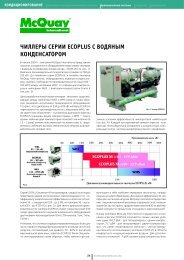
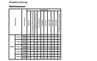
<strong>McSmart</strong> is the solution for residential <strong>and</strong> commercial applications.<br />
It is available in 7 sizes from 48 to 155 kW, in cooling only <strong>and</strong> <strong>heat</strong> pump versions, with R407C ecological<br />
refrigerant.<br />
It has been designed for high energy efficiency. The low noise emission meets every requirement for<br />
installation in residential areas.<br />
The microprocessor is compatible with Smart Manager, the McQuay solution that allows to control up to 50<br />
<strong>chillers</strong> <strong>and</strong> 256 fan coils. McQuay is able to cover the complete hydronic system with <strong>McSmart</strong> <strong>chillers</strong> <strong>and</strong><br />
fan coils series.<br />
<br />
<br />
<br />
<br />
<br />
<br />
<br />
MF series<br />
<br />
<br />
<br />
<br />
<br />
MWM series<br />
<br />
<br />
<br />
<br />
<br />
<br />
MCK series<br />
<br />
<br />
<br />
<br />
MCW series<br />
<br />
<br />
<br />
<br />
<br />
<br />
MCC series<br />
<br />
<br />
<br />
<br />
<br />
<br />
<br />
<br />
<br />
<br />
<br />
<br />
101 B – 05/07 A – pag. 3/28
!!<br />
Cabinet <strong>and</strong> structure<br />
The cabinet is made of galvanized steel sheet <strong>and</strong> painted to provide a high resistance to corrosion. The<br />
base frame has holes for easy moving by fork lift. The weight is uniformly distributed along the profiles of the<br />
base <strong>and</strong> this facilitates the arrangement of the unit’s bases <strong>and</strong> the support structures. The electrical <strong>and</strong><br />
control equipment is located in the control box.<br />
Scroll compressors<br />
The scroll compressors achieve a high volumetric efficiency, due to constant contact with the sides of the<br />
scroll spirals <strong>and</strong> the total absence of discharge <strong>and</strong> suction valves. These compressors are not only<br />
extremely reliable thanks to the reduced number of moving parts, but have an exceptionally low noise level<br />
because of the absence of suction <strong>and</strong> discharge valves <strong>and</strong> hence of the reduced pulsations of the<br />
discharge gas. The reduction in moving parts means a very low level of vibration.<br />
Evaporator<br />
The evaporator is a compact, efficient, dual circuit plate to plate type <strong>heat</strong> exchanger consisting of stainless<br />
steel brazed plates.<br />
The evaporator is wrapped with closed cell <strong>heat</strong> insulation <strong>and</strong> equipped with an <strong>heat</strong>er for protection against<br />
freezing down to –29°C.<br />
Condenser coils<br />
The condenser coils are made of internally enhanced seamless copper tubes arranged in a staggered row<br />
pattern <strong>and</strong> mechanically exp<strong>and</strong>ed into lanced <strong>and</strong> rippled aluminium condenser fins with full fin collars.<br />
Condenser coil fans<br />
The condenser fans are axial helical type; the blades profile is optimised to achieve the best performance.<br />
The direct coupling with the electrical motor eliminates the problems related to transmission devices <strong>and</strong><br />
reduces the vibrations caused by the functioning. The motors are supplied as st<strong>and</strong>ard with IP54 protection<br />
<strong>and</strong> are mono-phase external rotor type; they are protected against overload by thermal relays located inside<br />
the electrical control panel.<br />
Electrical panel<br />
The panel is manufactured to ensure protection in all weather conditions (IP 54). It complies with IEC204-1<br />
safety norms. The power panel is fitted with a door interlocked mains isolator to prevent access. The power<br />
section includes thermal relays for compressors <strong>and</strong> fans.<br />
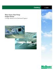
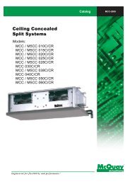
Control devices<br />
The microprocessor controller can be used either as a single st<strong>and</strong>-alone or as an extended network system.<br />
The control panel consists of a main board <strong>and</strong> a wired remote keypad with 8 lines graphical LCD display.<br />
The 8 available keys in the panel allow the user to do the following tasks:<br />
− Menu selection<br />
− Navigation on the screen<br />
− Modification of the selected value<br />
1 & 2 Navigator key<br />
3 Execute instruction key<br />
4 Cancel instruction key<br />
5 Switching to <strong>heat</strong> mode shortcut key<br />
6 Switching to cool mode shortcut key<br />
7 Toggle ON/OFF shortcut key<br />
8 Show alarm key<br />
9 Graphical LCD display<br />
10 ON/OFF indicator<br />
<br />
During start-up, the panel will have a default configuration (timer schedule, set point, settings, etc) which can<br />
be later modified by the user.<br />
101 B – 05/07 A – pag. 4/28
Main characteristics<br />
Status viewing:<br />
• ON/OFF status<br />
• Operating mode (cooling/<strong>heat</strong>ing/boiler)<br />
• Set temperature<br />
• Compressor status (ON/OFF/DEFROST)<br />
• Inlet water, outlet water, outdoor air <strong>and</strong> panel temperatures<br />
• Advance parameter settings<br />
• Defrost sensor temperatures<br />
• Compressor discharge sensor temperatures<br />
• Compressor run time<br />
• Incoming alarm/fault/error<br />
Status settings:<br />
• ON/OFF switching<br />
• Operating mode setting (cooling/<strong>heat</strong>ing/boiler)<br />
• Setting temperature<br />
• Manual entering defrost<br />
• Advance parameter settings<br />
• Password changing<br />
• Panel option setting (backlight, alarm buzzer, screen saver, contrast, brightness, temperature unit)<br />
• Time <strong>and</strong> date settings<br />
• 7 day programmable settings<br />
• Compressor run time reset<br />
Menu structure<br />
<br />
<br />
<br />
<br />
<br />
<br />
<br />
<br />
<br />
<br />
<br />
<br />
<br />
<br />
<br />
<br />
<br />
<br />
<br />
<br />
St<strong>and</strong>ards reference<br />
Every unit is designed, manufactured, tested according to CE marked.<br />
Quality management system is approved by RINA in compliance with UNI - EN ISO 9001:2000 st<strong>and</strong>ards.<br />
101 B – 05/07 A – pag. 5/28
!!"!<br />
St<strong>and</strong>ard accessories<br />
Fan thermal overload relays – safety devices against fans motor overload.<br />
Compressor thermal overload relays – safety devices against compressor motor overload.<br />
Phase monitor – safety device against reversal of phase.<br />
Condenser coil guards – metal protection guards fixed on the external surface of the condenser coils.<br />
Compressor coil guards – metal protection guards to prevent unauthorised access to the components<br />
under the condenser coils section.<br />
Water pressure differential switch – safety device against missing evaporator water flow.<br />
Manometers – gauges for high gas pressure <strong>and</strong> low gas pressure.<br />
Vibration-dampings – rubber type for <strong>160</strong>÷240 unit models, spring type for 320÷<strong>500</strong> unit models.<br />
Options on request<br />
Low ambient kit - device that allows fan speed modulation, modifying air flow according to external<br />
temperature conditions down to -10°C.<br />
Two water circulation <strong>pumps</strong> kit (factory unit mounted) – with the following components.<br />
Water <strong>pumps</strong>: each unit has two water <strong>pumps</strong> as option, with a selection switch to chose which one to run.<br />
Maximum working pressure is 6 bar.<br />
Filling valve: auto-operated to fill water whenever the water pressure is lower due to water absence.<br />
<strong>Air</strong> vent: to vent air in the hydraulic circuit.<br />
Safety valve: acts whenever faulty service leads to an operating pressure in the hydraulic circuit that exceeds the<br />
valve opening value.<br />
Expansion tank: 8 l for <strong>160</strong>÷320 unit models, 18 l for 400÷<strong>500</strong> unit models; it absorbs volume variation in the<br />
water circuit.<br />
Stop valves: installed on both water pump inlet <strong>and</strong> outlet.<br />
Water filter: installed before the water pump, retains impurities.<br />
Purge valve: drain for maintenance.<br />
Manometer: installed on the filling valve to display the water pressure for circuit.<br />
<br />
<br />
<br />
<br />
<br />
<br />
<br />
<br />
<br />
<br />
<br />
<br />
<br />
<br />
<br />
<br />
<br />
<br />
<br />
<br />
<br />
<br />
<br />
<br />
<br />
101 B – 05/07 A – pag. 6/28
#$ !<br />
OPERATING LIMITS Cooling only Heat pump<br />
Ambient air<br />
Maximum temperature in cooling mode +48°C +48°C<br />
Minimum temperature in cooling mode for <strong>McSmart</strong> <strong>160</strong>÷240 +12°C (1) +12°C (1)<br />
Minimum temperature in cooling mode for <strong>McSmart</strong> 320÷<strong>500</strong> +15°C (1) +15°C (1)<br />
Maximum temperature in <strong>heat</strong>ing mode<br />
Minimum temperature in <strong>heat</strong>ing mode<br />
Evaporator water<br />
+26°C<br />
Maximum outlet temperature in cooling mode +10°C +10°C<br />
Minimum outlet temperature without glycol in cooling mode +5°C +5°C<br />
Minimum outlet temperature with glycol in cooling mode -8°C -8°C<br />
Maximum outlet temperature in <strong>heat</strong>ing mode<br />
Minimum outlet temperature in <strong>heat</strong>ing mode<br />
Maximum ∆T 8°C 8°C<br />
Minimum ∆T 4°C 4°C<br />
<br />
(1) –10°C with low ambient kit option.<br />
%" &'(! %"!<br />
-7°C<br />
+55°C<br />
+35°C<br />
Evaporator fouling factors<br />
Fouling factors<br />
m 2 °C / kW<br />
Cooling capacity<br />
Power input<br />
correction factor<br />
correction factor<br />
0,0176 1,000 1,000 1,000<br />
COP<br />
correction factor<br />
0,0440 0,978 0,986 0,992<br />
0,0880 0,957 0,974 0,983<br />
0,1320 0,938 0,962 0,975<br />
Altitude correction factors<br />
Elevation above sea level (m) 0 300 600 900 1200 1<strong>500</strong> 1800<br />
Barometric pressure (mbar) 1013 977 942 908 875 843 812<br />
Cooling cap. correction factor 1,000 0,993 0,986 0,979 0,973 0,967 0,960<br />
Power input correction factor 1,000 1,005 1,009 1,015 1,021 1,026 1,031<br />
Ethylene glycol <strong>and</strong> low ambient temperature correction factors<br />
<strong>Air</strong> ambient temperature °C -3 -8 -15 -23 -35<br />
% of ethylene glycol by weight 10 20 30 40 50<br />
Cooling capacity correction factor 0,991 0,982 0,972 0,961 0,946<br />
Power input correction factor 0,996 0,992 0,986 0,976 0,966<br />
Flow rate correction factor 1,013 1,040 1,074 1,121 1,178<br />
Water pressure drop correction factor 1,070 1,129 1,181 1,263 1,308<br />
Low temperature operation performance factors<br />
Ethylene glycol/water leaving temperature °C 2 0 -2 -4 -6 -8<br />
Max air ambient temperature °C 40 39 38 37 36 35<br />
Cooling capacity correction factor 0,842 0,785 0,725 0,670 0,613 0,562<br />
Power input compressors correction factor 0,95 0,94 0,92 0,89 0,87 0,84<br />
Min. % of ethylene glycol 10 20 20 30 30 30<br />
Low temperature operation performance factors must be applied to the nominal performance data to have the adjusted value (12/7°C,<br />
design ambient temperature).<br />
101 B – 05/07 A – pag. 7/28
&<br />
Cooling only<br />
<strong>McSmart</strong> <strong>160</strong>C 190C 210C 240C 320C 400C <strong>500</strong>C<br />
Cooling capacity (1) kW 47,8 57,9 70,5 81,2 98,0 124,3 154,8<br />
Power input (1) kW 18,4 21,1 24,2 28,6 37,5 42,4 52,3<br />
COP 2,60 2,74 2,91 2,84 2,61 2,93 2,96<br />
Compressor<br />
Quantity 2 2 2 2 4 4 4<br />
Total oil charge l 6,5 6,5 8,0 13,0 13,0 13,0 26,4<br />
Reduction steps number 2 2 2 2 4 4 4<br />
Refrigerant<br />
Scroll<br />
R407C<br />
Circuits number 2 2 1 1 2 2 2<br />
Charge kg 12,6 14,0 22,0 20,5 29,0 48,0 64,0<br />
Condenser coil<br />
Fan<br />
Lanced fins – internally spiral wound tubes<br />
Helical<br />
Quantity 2 2 2 2 2 4 4<br />
Power input kW 0,72 0,72 0,72 0,72 1,90 0,72 0,72<br />
Speed RPM 715 715 715 715 715 715 715<br />
Diameter mm 710 710 800 800 800 800 800<br />
Evaporator<br />
Plate <strong>heat</strong> exchanger<br />
Quantity 1 1 1 1 1 1 1<br />
Water volume l 8,0 9,5 10,0 12,8 12,3 18,0 25,5<br />
Maximum water pressure bar 30 30 30 30 30 30 30<br />
Water connections diameter “ Rc 1 1/ 2 Rc 1 1/ 2 Rc 1 1/ 2 Rc 1 1/ 2 Rc 2 Rc 2 Rc 2<br />
Dimensions <strong>and</strong> weight<br />
Length mm 1820 1820 2056 2056 2750 2750 2750<br />
Width mm 1000 1000 1153 1153 1100 2200 2200<br />
Height mm 1935 1935 2185 2185 2180 2180 2180<br />
St<strong>and</strong>ard unit shipping weight kg 637 651 843 906 1155 1543 1899<br />
St<strong>and</strong>ard unit operating weight kg 650 666 864 942 1175 1571 1935<br />
Shipping weight with <strong>pumps</strong> kit kg 661 675 878 941 1190 1580 2055<br />
Operating weight with <strong>pumps</strong> kit kg 674 690 899 977 1210 <strong>160</strong>7 2092<br />
Electrical data<br />
St<strong>and</strong>ard voltage (2)<br />
400 V – 3ph + N – 50 Hz<br />
Nominal unit current (1) (3) A 32,8 36,7 43,2 50,1 69,8 76,7 100,5<br />
Maximum compressors current (4) A 34,8 41,0 47,8 56,6 75,6 80,4 108,0<br />
Maximum water pump current A 3,1 3,1 5,4 5,4 5,4 6,4 8,5<br />
Maximum fans current A 4,2 4,2 6,2 6,2 7,0 12,4 12,4<br />
Maximum unit current (3) (4) A 40,9 47,1 53,9 62,7 82,5 91,5 116,8<br />
Maximum unit inrush current (5) A 116,7 135,3 155,7 182,1 159,5 174,7 217,2<br />
Maximum unit current for wires sizing (6) A 54,8 63,6 73,1 85,4 105,0 112,4 136,2<br />
(1) Nominal cooling capacity <strong>and</strong> power input are based on: 12/7 °C entering/leaving evaporator water temperature; 35°C<br />
ambient temperature.<br />
(2) Allowed voltage tolerance ± 10%. Voltage unbalance between phases must be within ± 3%.<br />
(3) Without pump.<br />
(4) Maximum current are based on: 15/10 °C entering/leaving evaporator water temperature <strong>and</strong> 48°C ambient temp.<br />
(5) Inrush current of biggest compressor + nominal absorbed current of the other compressors + fans current.<br />
(6) Compressor FLA + fans current.<br />
101 B – 05/07 A – pag. 8/28
&<br />
Heat pump<br />
<strong>McSmart</strong> <strong>160</strong>CR 190CR 210CR 240CR 320CR 400CR <strong>500</strong>CR<br />
Cooling capacity (1) kW 47,1 52,9 63,6 75,6 96,0 112,6 144,7<br />
Power input (1) kW 18,3 20,1 23,4 27,1 35,5 41,0 50,7<br />
Heating capacity (2) kW 55,1 57,1 67,2 81,8 110,3 118,1 157,5<br />
Power input (2) kW 19,5 20,7 25,6 28,5 38,1 45,4 57,3<br />
COP (1) 2,57 2,63 2,72 2,79 2,70 2,75 2,85<br />
Compressor<br />
Quantity 2 2 2 2 4 4 4<br />
Total oil charge l 6,5 6,5 8,0 13,0 13,0 13,0 26,4<br />
Reduction steps number 2 2 2 2 4 4 4<br />
Refrigerant<br />
Scroll<br />
R407C<br />
Circuits number 2 2 1 1 2 2 2<br />
Charge kg 13,0 15,0 26,0 26,0 42,0 42,0 56,0<br />
Condenser coil<br />
Lanced fins – internally spiral wound tubes<br />
Fan<br />
Helical<br />
Quantity 2 2 2 2 2 4 4<br />
Power input kW 0,72 0,72 0,72 0,72 1,90 0,72 0,72<br />
Speed RPM 715 715 715 715 715 715 715<br />
Diameter mm 710 710 800 800 800 800 800<br />
Evaporator<br />
Plate <strong>heat</strong> exchanger<br />
Quantity 1 1 1 1 1 1 1<br />
Water volume l 8,0 9,5 10,0 12,8 12,3 18,0 25,5<br />
Maximum water pressure bar 30 30 30 30 30 30 30<br />
Water connections diameter “ Rc 1 1/ 2 Rc 1 1/ 2 Rc 1 1/ 2 Rc 1 1/ 2 Rc 2 Rc 2 Rc 2<br />
Dimensions <strong>and</strong> weight<br />
Length mm 1820 1820 2056 2056 2750 2750 2750<br />
Width mm 1000 1000 1153 1153 1100 2200 2200<br />
Height mm 1935 1935 2185 2185 2180 2180 2180<br />
St<strong>and</strong>ard unit shipping weight kg 650 676 885 928 1206 1583 1988<br />
St<strong>and</strong>ard unit operating weight kg 663 691 906 964 1226 1611 2024<br />
Shipping weight with <strong>pumps</strong> kit kg 674 700 920 963 1241 1620 2154<br />
Operating weight with <strong>pumps</strong> kit kg 687 715 941 999 1261 1648 2190<br />
Electrical data<br />
St<strong>and</strong>ard voltage (3)<br />
400 V – 3ph + N – 50 Hz<br />
Nominal unit current (1) (4) A 32,6 35,8 41,9 49,7 66,1 74,2 97,4<br />
Maximum compressors current (5) A 34,8 41,0 47,8 56,6 75,6 80,4 108,0<br />
Maximum water pump current A 3,1 3,1 5,4 5,4 5,4 6,4 8,5<br />
Maximum fans current A 4,2 4,2 6,2 6,2 9,0 12,4 12,4<br />
Maximum unit current (3) (5) A 40,9 47,1 53,9 62,7 82,5 91,5 116,8<br />
Maximum unit inrush current (6) A 116,7 135,3 155,7 182,1 159,5 174,7 217,2<br />
Maximum unit current for wires sizing (7) A 54,8 63,6 73,1 85,4 105,0 112,4 136,2<br />
(1) Nominal cooling capacity <strong>and</strong> power input are based on: 12/7 °C entering/leaving evaporator water temperature; 35°C<br />
ambient temperature.<br />
(2) Nominal <strong>heat</strong>ing capacity <strong>and</strong> power input are based on: 40/45 °C entering/leaving evaporator water temperature; 7°C(dry<br />
bulb)/6°C(wet bulb) ambient temperature.<br />
(3) Allowed voltage tolerance ± 10%. Voltage unbalance between phases must be within ± 3%.<br />
(4) Without pump.<br />
(5) Maximum current are based on: 15/10 °C entering/leaving evaporator water temperature <strong>and</strong> 48°C ambient temp.<br />
(6) Inrush current of biggest compressor + nominal absorbed current of the other compressors + fans current.<br />
(7) Compressor FLA + fans current.<br />
101 B – 05/07 A – pag. 9/28
"(&)!<br />
<br />
Cooling only<br />
<br />
<strong>McSmart</strong><br />
Sound pressure level at 1 m from the unit in free field ( rif. 2 x 10 -5 )<br />
63 Hz 125 Hz 250 Hz <strong>500</strong> Hz 1000 Hz 2000 Hz 4000 Hz 8000 Hz dBA<br />
<strong>160</strong>C 73,5 67,5 65,6 64,8 60,6 55,4 47,6 39,3 65,8<br />
190C 73,1 69,8 63,8 64,6 62,9 57,7 53,6 48,7 67,0<br />
210C 75,3 66,6 64,6 64,8 62,3 58,9 55,4 49,9 67,2<br />
240C 75,3 66,6 64,1 64,5 62,4 58,7 52,9 45,7 66,9<br />
320C 80,3 75,7 69,0 66,9 66,7 62,2 58,1 55,0 71,0<br />
400C 80,4 72,1 69,0 68,9 65,9 62,4 57,8 51,3 71,0<br />
<strong>500</strong>C 78,3 72,5 68,5 70,2 66,3 64,4 59,8 56,4 72,0<br />
Average sound pressure level rated in accordance to ISO 3744, at free field semispherical conditions.<br />
<br />
<br />
<br />
Heat pump<br />
Unit size<br />
Sound pressure level at 1 m from the unit in free field ( rif. 2 x 10 -5 )<br />
63 Hz 125 Hz 250 Hz <strong>500</strong> Hz 1000 Hz 2000 Hz 4000 Hz 8000 Hz dBA<br />
<strong>160</strong>CR 73,5 67,5 65,6 64,8 60,6 55,4 47,6 39,3 65,8<br />
190CR 73,1 69,8 63,8 64,6 62,9 57,7 53,6 48,7 67,0<br />
210CR 75,3 66,6 64,6 64,8 62,3 58,9 55,4 49,9 67,2<br />
240CR 75,3 66,6 64,1 64,5 62,4 58,7 52,9 45,7 66,9<br />
320CR 80,3 75,7 69,0 66,9 66,7 62,2 58,1 55,0 71,0<br />
400CR 80,4 72,1 69,0 68,9 65,9 62,4 57,8 51,3 71,0<br />
<strong>500</strong>CR 78,3 72,5 68,5 70,2 66,3 64,4 59,8 56,4 72,0<br />
Average sound pressure level rated in accordance to ISO 3744, free field semispherical conditions.<br />
101 B – 05/07 A – pag. 10/28
# *#%"<br />
Cooling only<br />
Unit<br />
size<br />
<strong>160</strong><br />
190<br />
210<br />
240<br />
320<br />
400<br />
<strong>500</strong><br />
Evaporator<br />
leaving temp.<br />
(°C)<br />
Cooling<br />
capacity<br />
(kW)<br />
AMBIENT TEMPERATURE - °C<br />
21 25 30 32<br />
Power<br />
input<br />
(kW)<br />
Cooling<br />
capacity<br />
(kW)<br />
Power<br />
input<br />
(kW)<br />
Cooling<br />
capacity<br />
(kW)<br />
Power<br />
input<br />
(kW)<br />
Cooling<br />
capacity<br />
5 51,6 14,9 49,5 15,9 48,2 16,5 47,3 16,9<br />
6 53,1 15,2 51,0 16,1 49,7 16,7 48,7 17,2<br />
7 54,5 15,6 52,4 16,4 51,0 17,0 50,1 17,4<br />
8 56,1 15,8 54,0 16,7 52,5 17,3 51,6 17,7<br />
9 57,8 15,7 55,4 16,9 54,0 17,5 53,0 17,9<br />
10 59,1 16,1 57,0 17,2 55,4 17,9 54,5 18,3<br />
5 62,4 17,1 60,0 18,2 58,3 18,9 57,2 19,3<br />
6 64,4 17,5 61,7 18,5 60,1 19,2 59,0 19,7<br />
7 65,9 17,8 63,5 18,8 61,7 19,5 60,7 20,0<br />
8 67,8 18,1 65,3 19,1 63,5 19,8 62,4 20,3<br />
9 69,8 18,0 67,1 19,4 65,4 20,1 64,2 20,6<br />
10 71,6 18,5 69,1 19,7 67,2 20,5 65,9 21,0<br />
5 75,9 19,6 73,0 20,9 71,0 21,7 69,7 22,2<br />
6 78,3 20,1 75,2 21,2 73,2 22,0 71,8 22,6<br />
7 80,3 20,5 77,3 21,6 75,3 22,4 73,8 22,9<br />
8 82,6 20,8 79,6 22,0 77,4 22,7 76,0 23,3<br />
9 85,1 20,6 81,8 22,2 79,6 23,1 78,1 23,6<br />
10 87,2 21,2 84,1 22,6 81,8 23,5 80,3 24,1<br />
5 87,5 23,2 84,1 24,7 81,8 25,6 80,3 26,2<br />
6 90,2 23,7 86,6 25,1 84,3 26,0 82,7 26,7<br />
7 92,5 24,2 89,1 25,5 86,6 26,5 85,1 27,1<br />
8 95,1 24,6 91,6 25,9 89,1 26,9 87,5 27,5<br />
9 98,1 24,3 94,2 26,3 91,7 27,3 90,0 27,9<br />
10 100,5 25,1 96,9 26,7 94,2 27,8 92,5 28,4<br />
5 105,6 30,4 101,5 32,4 98,7 33,6 96,9 34,4<br />
6 108,9 31,1 104,6 32,9 101,7 34,1 99,9 35,0<br />
7 111,6 31,7 107,5 33,5 104,6 34,7 102,7 35,5<br />
8 114,9 32,2 110,6 34,0 107,6 35,2 105,7 36,1<br />
9 118,3 31,9 113,7 34,4 110,7 35,7 108,7 36,6<br />
10 121,3 32,9 117,0 35,0 113,7 36,4 111,6 37,3<br />
5 134,1 34,3 128,8 36,6 125,3 38,0 123,0 38,9<br />
6 138,2 35,1 132,7 37,2 129,2 38,6 126,7 39,5<br />
7 141,8 35,8 136,5 37,9 132,8 39,3 130,3 40,2<br />
8 145,8 36,4 140,4 38,5 136,6 39,8 134,1 40,8<br />
9 150,2 36,1 144,3 38,9 140,5 40,4 138,0 41,4<br />
10 153,8 37,2 148,4 39,6 144,4 41,2 141,8 42,2<br />
5 167,0 42,5 <strong>160</strong>,5 45,3 156,1 47,0 153,2 48,1<br />
6 172,1 43,5 165,2 46,1 <strong>160</strong>,9 47,8 157,8 48,9<br />
7 176,4 44,4 169,9 46,9 165,3 48,6 162,4 49,8<br />
8 181,6 45,1 174,7 47,6 170,1 49,3 167,1 50,5<br />
9 187,0 44,7 179,7 48,2 175,0 50,0 171,8 51,2<br />
10 191,6 46,0 184,8 49,0 179,8 51,0 176,4 52,2<br />
<br />
Notes: (1) Rating based on: evaporator fouling factor of 0,0176 m 2 °C / kW, evaporator temperature drop of 5°C <strong>and</strong> sea level<br />
altitude.<br />
(2) Interpolation is allowed. Extrapolation is not permitted. Please contact McQuay for performance outside the<br />
st<strong>and</strong>ard ratings.<br />
(3) Power input values are referred to compressor only.<br />
(kW)<br />
Power<br />
input<br />
(kW)<br />
101 B – 05/07 A – pag. 11/28
# *#%"<br />
Cooling only<br />
Unit<br />
size<br />
<strong>160</strong><br />
190<br />
210<br />
240<br />
320<br />
400<br />
<strong>500</strong><br />
Evaporator<br />
leaving temp.<br />
(°C)<br />
Cooling<br />
capacity<br />
(kW)<br />
101 B – 05/07 A – pag. 12/28<br />
AMBIENT TEMPERATURE - °C<br />
35 40 43 48<br />
Power<br />
input<br />
(kW)<br />
Cooling<br />
capacity<br />
(kW)<br />
Power<br />
input<br />
(kW)<br />
Cooling<br />
capacity<br />
(kW)<br />
Power<br />
input<br />
(kW)<br />
Cooling<br />
capacity<br />
5 45,0 17,9 42,6 18,8 41,7 19,2 39,7 19,8<br />
6 46,4 18,1 44,0 19,1 43,1 19,4 41,2 20,5<br />
7 47,8 18,4 45,3 19,3 44,3 19,7 42,0 20,7<br />
8 49,1 18,7 46,6 19,6 45,6 20,0 43,4 21,0<br />
9 50,5 19,0 48,0 19,9 46,9 20,1 44,8 19,7<br />
10 52,0 19,3 49,6 20,0 48,1 20,4 45,8 20,9<br />
5 54,5 20,5 51,7 21,6 50,5 22,0 48,1 22,7<br />
6 56,2 20,8 53,2 21,9 52,1 22,3 49,9 23,5<br />
7 57,9 21,1 54,8 22,2 53,7 22,6 50,9 23,7<br />
8 59,5 21,4 56,4 22,5 55,2 22,9 52,5 24,0<br />
9 61,1 21,7 58,1 22,8 56,8 23,1 54,3 22,6<br />
10 62,9 22,1 60,0 23,0 58,3 23,4 55,4 23,9<br />
5 66,4 23,5 62,9 24,7 61,5 25,2 58,6 26,0<br />
6 68,4 23,9 64,8 25,1 63,4 25,6 60,7 26,9<br />
7 70,5 24,2 66,8 25,4 65,3 26,0 62,0 27,2<br />
8 72,6 24,5 68,7 25,8 67,2 26,3 63,9 27,6<br />
9 74,4 24,9 70,7 26,1 69,2 26,4 66,2 26,0<br />
(kW)<br />
Power<br />
input<br />
10 76,7 25,3 73,1 26,3 71,0 26,8 67,5 27,4<br />
5 76,6 27,8 72,5 29,2 70,8 29,8 67,4 30,7<br />
6 78,8 28,2 74,7 29,6 73,1 30,2 70,0 31,8<br />
7 81,2 28,6 77,0 30,1 75,2 30,7 71,3 32,1<br />
8 83,5 29,0 79,1 30,5 77,4 31,1 73,6 32,6<br />
9 85,8 29,5 81,5 30,9 79,7 31,3 76,2 30,7<br />
10 88,3 29,9 84,2 31,1 81,7 31,7 77,8 32,4<br />
5 92,3 36,4 87,5 38,3 85,6 39,1 81,5 40,3<br />
6 95,1 37,0 90,2 38,8 88,2 39,6 84,4 41,7<br />
7 98,0 37,5 92,8 39,4 90,8 40,2 86,2 42,1<br />
8 100,8 38,0 95,6 40,0 93,5 40,8 88,8 42,7<br />
9 103,5 38,6 98,3 40,5 96,3 41,0 92,0 40,2<br />
10 106,6 39,2 101,5 40,8 98,7 41,5 93,9 42,5<br />
5 117,2 41,2 111,0 43,3 108,6 44,2 103,3 45,6<br />
6 120,6 41,8 114,5 43,9 111,9 44,8 107,1 47,2<br />
7 124,3 42,4 117,8 44,6 115,2 45,5 109,3 47,6<br />
8 128,0 43,0 121,3 45,2 118,7 46,1 112,8 48,3<br />
9 131,4 43,7 124,7 45,8 122,1 46,3 116,8 45,5<br />
10 135,2 44,4 128,9 46,1 125,2 47,0 119,2 48,1<br />
5 145,9 51,0 138,2 53,6 135,2 54,7 128,8 56,4<br />
6 150,3 51,7 142,4 54,4 139,4 55,5 133,4 58,4<br />
7 154,8 52,3 146,8 55,2 143,5 56,3 136,1 59,0<br />
8 159,4 53,3 151,0 56,0 147,8 57,1 140,5 59,8<br />
9 163,6 54,1 155,3 56,7 152,1 57,4 145,4 56,3<br />
10 168,4 54,9 <strong>160</strong>,6 57,1 155,9 58,2 148,5 59,5<br />
<br />
Notes: (1) Rating based on: evaporator fouling factor of 0,0176 m 2 °C / kW, evaporator temperature drop of 5°C <strong>and</strong> sea level<br />
altitude.<br />
(2) Interpolation is allowed. Extrapolation is not permitted. Please contact McQuay for performance outside the<br />
st<strong>and</strong>ard ratings.<br />
(3) Power input values are referred to compressor only.<br />
(kW)
# *#%"<br />
Heat pump<br />
Unit<br />
size<br />
<strong>160</strong><br />
190<br />
210<br />
240<br />
320<br />
400<br />
<strong>500</strong><br />
Evaporator<br />
leaving temp.<br />
(°C)<br />
Cooling<br />
capacity<br />
(kW)<br />
AMBIENT TEMPERATURE - °C<br />
21 25 30 32<br />
Power<br />
input<br />
(kW)<br />
Cooling<br />
capacity<br />
(kW)<br />
Power<br />
input<br />
(kW)<br />
Cooling<br />
capacity<br />
(kW)<br />
Power<br />
input<br />
(kW)<br />
Cooling<br />
capacity<br />
5 50,8 14,8 48,8 15,8 47,6 16,4 46,6 16,8<br />
6 52,4 15,2 50,3 16,1 48,9 16,7 48,1 17,1<br />
7 53,8 15,5 51,8 16,3 50,4 16,9 49,5 17,3<br />
8 55,3 15,7 53,2 16,6 51,8 17,2 50,8 17,6<br />
9 56,9 15,6 54,7 16,8 53,2 17,4 52,3 17,9<br />
10 58,4 16,0 56,3 17,1 54,7 17,8 53,8 18,2<br />
5 57,0 16,3 54,8 17,3 53,3 18,0 52,4 18,4<br />
6 58,8 16,7 56,5 17,6 55,0 18,3 54,0 18,7<br />
7 60,3 17,0 58,1 17,9 56,5 18,6 55,4 19,1<br />
8 62,1 17,3 59,7 18,2 58,2 18,9 57,1 19,3<br />
9 63,9 17,1 61,4 18,5 59,7 19,2 58,7 19,6<br />
10 65,5 17,6 63,2 18,8 61,4 19,5 60,3 20,0<br />
5 68,6 19,0 65,9 20,2 64,2 20,9 63,0 21,5<br />
6 70,8 19,4 67,9 20,5 66,2 21,3 64,9 21,8<br />
7 72,6 19,8 69,8 20,9 67,9 21,7 66,7 22,2<br />
8 74,7 20,1 71,8 21,2 69,9 22,0 68,7 22,5<br />
9 76,9 19,9 73,8 21,5 71,9 22,3 70,6 22,8<br />
10 78,8 20,5 75,9 21,8 73,9 22,7 72,6 23,3<br />
5 81,6 22,0 78,3 23,4 76,3 24,3 74,9 24,8<br />
6 84,1 22,5 80,8 23,8 78,6 24,7 77,2 25,3<br />
7 86,2 22,9 83,1 24,2 80,9 25,1 79,3 25,7<br />
8 88,8 23,3 85,5 24,6 83,1 25,5 81,6 26,1<br />
9 91,3 23,1 87,8 24,9 85,5 25,8 83,9 26,4<br />
10 93,7 23,8 90,3 25,3 87,8 26,3 86,2 27,0<br />
5 103,4 28,8 99,4 30,6 96,7 31,8 94,9 32,5<br />
6 106,7 29,4 102,5 31,1 99,6 32,3 97,9 33,1<br />
7 109,4 30,0 105,3 31,7 102,5 32,9 100,6 33,7<br />
8 112,6 30,5 108,4 32,2 105,4 33,4 103,5 34,2<br />
9 115,9 30,2 111,4 32,6 108,5 33,8 106,5 34,6<br />
10 118,8 31,1 114,6 33,1 111,4 34,5 109,4 35,3<br />
5 121,4 33,2 116,7 35,4 113,5 36,7 111,4 37,6<br />
6 125,2 34,0 120,1 36,0 117,0 37,3 114,8 38,2<br />
7 128,3 34,6 123,6 36,6 120,2 38,0 118,0 38,9<br />
8 132,0 35,2 127,1 37,2 123,7 38,5 121,4 39,5<br />
9 136,0 34,9 130,6 37,7 127,2 39,1 124,8 40,0<br />
10 139,3 35,9 134,3 38,3 130,7 39,8 128,3 40,8<br />
5 156,1 41,1 150,0 43,7 145,9 45,4 143,3 46,5<br />
6 <strong>160</strong>,9 42,0 154,5 44,5 150,4 46,1 147,6 47,3<br />
7 165,0 42,8 158,9 45,3 154,6 46,9 151,8 48,1<br />
8 169,8 43,5 163,4 46,0 159,1 47,6 156,2 48,8<br />
9 174,8 43,2 168,0 46,6 163,5 48,3 <strong>160</strong>,6 49,5<br />
10 179,1 44,5 172,7 47,3 168,1 49,2 165,0 50,4<br />
<br />
Notes: (1) Rating based on: evaporator fouling factor of 0,0176 m 2 °C / kW, evaporator temperature drop of 5°C <strong>and</strong> sea level<br />
altitude.<br />
(2) Interpolation is allowed. Extrapolation is not permitted. Please contact McQuay for performance outside the<br />
st<strong>and</strong>ard ratings.<br />
(3) Power input values are referred to compressor only.<br />
(kW)<br />
Power<br />
input<br />
(kW)<br />
101 B – 05/07 A – pag. 13/28
# *#%"<br />
Heat pump<br />
Unit<br />
size<br />
<strong>160</strong><br />
190<br />
210<br />
240<br />
320<br />
400<br />
<strong>500</strong><br />
Evaporator<br />
leaving temp.<br />
(°C)<br />
Cooling<br />
capacity<br />
(kW)<br />
101 B – 05/07 A – pag. 14/28<br />
AMBIENT TEMPERATURE - °C<br />
35 40 43 48<br />
Power<br />
input<br />
(kW)<br />
Cooling<br />
capacity<br />
(kW)<br />
Power<br />
input<br />
(kW)<br />
Cooling<br />
capacity<br />
(kW)<br />
Power<br />
input<br />
(kW)<br />
Cooling<br />
capacity<br />
5 44,4 17,8 42,1 18,7 41,2 19,1 39,2 19,7<br />
6 45,8 18,0 43,4 19,0 42,4 19,3 40,6 20,4<br />
7 47,1 18,3 44,7 19,2 43,7 19,6 41,5 20,5<br />
8 48,5 18,6 46,0 19,5 44,9 19,9 42,7 20,9<br />
9 49,8 18,8 47,4 19,8 46,3 20,0 44,3 19,6<br />
10 51,2 19,1 48,9 19,9 47,5 20,3 45,2 20,7<br />
5 49,9 19,5 47,3 20,5 46,2 20,9 44,0 21,6<br />
6 51,3 19,8 48,7 20,8 47,7 21,2 45,6 22,4<br />
7 52,9 20,1 50,2 21,1 49,0 21,6 46,5 22,6<br />
8 54,5 20,4 51,7 21,4 50,5 21,8 48,0 22,9<br />
9 56,0 20,7 53,1 21,7 52,0 22,0 49,7 21,6<br />
10 57,5 21,0 54,9 21,9 53,3 22,3 50,7 22,8<br />
5 60,0 22,7 56,8 23,9 55,5 24,4 52,9 25,1<br />
6 61,7 23,1 58,6 24,2 57,2 24,7 54,8 26,0<br />
7 63,6 23,4 60,3 24,6 59,0 25,1 56,0 26,3<br />
8 65,5 23,7 62,1 25,0 60,7 25,4 57,8 26,7<br />
9 67,2 24,1 63,8 25,3 62,5 25,6 59,7 25,1<br />
10 69,2 24,5 65,9 25,5 64,1 25,9 61,0 26,5<br />
5 71,3 26,3 67,5 27,7 66,1 28,2 62,8 29,1<br />
6 73,4 26,7 69,6 28,1 68,2 28,6 65,2 30,1<br />
7 75,6 27,1 71,6 28,5 70,2 29,1 66,5 30,4<br />
8 77,9 27,5 73,8 28,9 72,3 29,5 68,7 30,9<br />
9 80,0 27,9 76,0 29,3 74,4 29,6 71,0 29,1<br />
10 82,3 28,4 78,4 29,5 76,2 30,0 72,6 30,7<br />
5 90,5 34,5 85,7 36,3 83,8 37,0 79,8 38,1<br />
6 93,1 35,0 88,3 36,8 86,4 37,5 82,7 39,5<br />
7 96,0 35,5 90,9 37,3 88,9 38,1 84,4 39,9<br />
8 98,8 36,0 93,7 37,9 91,6 38,6 87,0 40,5<br />
9 101,4 36,6 96,3 38,3 94,3 38,8 90,1 38,1<br />
10 104,4 37,1 99,5 38,6 96,6 39,3 92,0 40,2<br />
5 106,1 39,8 100,5 41,9 98,3 42,7 93,6 44,1<br />
6 109,2 40,4 103,5 42,5 101,3 43,3 97,0 45,6<br />
7 112,6 41,0 106,7 43,1 104,4 44,0 99,0 46,0<br />
8 115,8 41,6 109,8 43,7 107,4 44,6 102,2 46,7<br />
9 119,0 42,2 113,0 44,3 110,6 44,8 105,6 44,0<br />
10 122,4 42,9 116,7 44,6 113,4 45,4 107,9 46,5<br />
5 136,5 49,2 129,3 51,8 126,5 52,8 120,4 54,5<br />
6 140,5 50,0 133,2 52,5 130,3 53,6 124,7 56,4<br />
7 144,7 50,7 137,3 53,3 134,1 54,4 127,4 56,9<br />
8 149,0 51,4 141,2 54,1 138,1 55,1 131,3 57,8<br />
9 152,9 52,2 145,3 54,8 142,2 55,4 135,9 54,4<br />
10 157,5 53,0 150,1 55,1 145,8 56,2 138,8 57,5<br />
<br />
Notes: (1) Rating based on: evaporator fouling factor of 0,0176 m 2 °C / kW, evaporator temperature drop of 5°C <strong>and</strong> sea level<br />
altitude.<br />
(2) Interpolation is allowed. Extrapolation is not permitted. Please contact McQuay for performance outside the<br />
st<strong>and</strong>ard ratings.<br />
(3) Power input values are referred to compressor only.<br />
(kW)<br />
Power<br />
input<br />
(kW)
# *#%"<br />
Heat pump<br />
Unit<br />
size<br />
<strong>160</strong><br />
190<br />
210<br />
240<br />
320<br />
400<br />
<strong>500</strong><br />
Leaving water<br />
temperature<br />
(°C)<br />
Heating<br />
capacity<br />
(kW)<br />
AMBIENT TEMPERATURE - °C<br />
-5 0 5 7 10<br />
Power<br />
input<br />
(kW)<br />
Heating<br />
capacity<br />
(kW)<br />
Power<br />
input<br />
(kW)<br />
Heating<br />
capacity<br />
(kW)<br />
Power<br />
input<br />
(kW)<br />
Heating<br />
capacity<br />
(kW)<br />
Power<br />
input<br />
(kW)<br />
Heating<br />
capacity<br />
35 41,9 14,8 48,5 16,0 55,7 17,2 58,5 17,6 62,9 18,1<br />
40 40,2 15,2 46,8 16,2 54,1 17,7 56,8 18,3 61,2 19,1<br />
45 38,6 15,6 45,3 17,0 52,4 18,5 55,1 19,5 59,5 19,9<br />
50 37,0 16,0 43,6 17,6 50,7 19,1 53,4 19,7 57,9 20,3<br />
55 35,3 16,4 41,9 18,1 49,0 19,7 51,9 19,9 56,3 20,5<br />
35 43,4 15,7 50,3 17,0 57,6 18,2 60,6 18,6 65,1 19,3<br />
40 41,7 16,1 48,5 17,2 56,0 18,8 58,8 19,5 63,4 20,3<br />
45 40,0 16,6 46,8 18,0 54,3 19,7 57,1 20,7 61,7 21,1<br />
50 38,2 17,0 45,2 18,6 52,5 20,3 55,4 20,9 60,0 21,5<br />
55 36,5 17,4 43,4 19,3 50,8 20,9 53,7 21,1 58,3 21,7<br />
35 51,0 19,5 59,1 21,0 67,8 22,5 71,2 23,0 76,7 23,8<br />
40 49,0 20,0 57,1 21,2 65,8 23,3 69,2 24,1 74,6 25,1<br />
45 47,0 20,5 55,1 22,3 63,8 24,3 67,2 25,6 72,6 26,1<br />
50 45,0 21,0 53,1 23,0 61,8 25,1 65,2 25,9 70,6 26,6<br />
55 43,1 21,5 51,0 23,8 59,9 25,9 63,2 26,1 68,6 26,9<br />
35 62,2 21,7 72,0 23,4 82,6 25,1 86,7 25,7 93,2 26,5<br />
40 59,8 22,2 69,5 23,7 80,2 25,9 84,3 26,8 90,8 27,9<br />
45 57,3 22,8 67,0 24,8 77,7 27,1 81,8 28,5 88,4 29,1<br />
50 54,7 23,4 64,6 25,7 75,2 27,9 79,3 28,8 85,9 29,6<br />
55 52,3 23,9 62,2 26,5 72,8 28,8 76,9 29,1 83,4 29,9<br />
35 83,8 29,0 97,0 31,2 111,4 33,5 116,9 34,3 125,7 35,4<br />
40 80,5 29,7 93,8 31,6 108,0 34,7 113,6 35,8 122,4 37,3<br />
45 77,2 30,5 90,4 33,1 104,8 36,2 110,3 38,1 119,1 38,9<br />
50 73,9 31,2 87,2 34,3 101,4 37,3 107,0 38,5 115,8 39,6<br />
55 70,6 32,0 83,8 35,4 98,2 38,5 103,6 38,9 112,5 40,0<br />
35 89,8 34,5 104,0 37,2 119,3 40,0 125,3 40,9 134,7 42,2<br />
40 86,2 35,4 100,4 37,7 115,8 41,3 121,7 42,7 131,1 44,5<br />
45 82,7 36,3 96,9 39,5 112,2 43,1 118,1 45,4 127,6 46,3<br />
50 79,2 37,2 93,3 40,9 108,7 44,5 114,6 45,9 124,0 47,2<br />
55 75,6 38,2 89,8 42,3 105,1 46,0 111,1 46,4 120,5 47,8<br />
35 119,7 43,5 138,6 47,0 159,1 50,4 167,0 51,6 179,6 53,3<br />
40 114,9 44,7 133,8 47,6 154,3 52,1 162,3 53,9 174,7 56,2<br />
45 110,3 45,8 129,2 49,9 149,7 54,4 157,5 57,3 170,1 58,4<br />
50 105,5 47,0 124,4 51,6 144,8 56,2 152,7 57,9 165,3 59,6<br />
55 100,8 48,1 119,7 53,3 140,2 57,9 148,1 58,4 <strong>160</strong>,7 60,2<br />
<br />
Notes: (1) Rating based on: evaporator fouling factor of 0,0176 m 2 °C / kW, evaporator temperature drop of 5°C <strong>and</strong> sea level<br />
altitude.<br />
(2) Interpolation is allowed. Extrapolation is not permitted. Please contact McQuay for performance outside the<br />
st<strong>and</strong>ard ratings.<br />
(3) Power input values are referred to compressor only.<br />
(kW)<br />
Power<br />
input<br />
(kW)<br />
101 B – 05/07 A – pag. 15/28
% $&*&( ( !<br />
COOLING ONLY<br />
<strong>McSmart</strong> <strong>160</strong>C - 190C<br />
<br />
<br />
<br />
<br />
<br />
<br />
<br />
<br />
<br />
<br />
<br />
<br />
<br />
<br />
<br />
<br />
<br />
<br />
<br />
<br />
<br />
<br />
<br />
<br />
<strong>McSmart</strong> 210C - 240C - 320C - 400C - <strong>500</strong>C<br />
<br />
<br />
<br />
<br />
<br />
<br />
<br />
<br />
<br />
<br />
<br />
<br />
<br />
<br />
<br />
<br />
101 B – 05/07 A – pag. 16/28
% $&*&( ( !<br />
HEAT PUMP<br />
<strong>McSmart</strong> <strong>160</strong>CR - 190CR<br />
<strong>McSmart</strong> 210CR - 240CR - 320CR - 400CR - <strong>500</strong>CR<br />
101 B – 05/07 A – pag. 17/28
! "<br />
H<strong>and</strong>ling <strong>and</strong> space requirements<br />
<br />
H<strong>and</strong>ling<br />
All moving <strong>and</strong> h<strong>and</strong>ling may damage the unit if some conditions are not scrupulously observed. The units<br />
should be lifted with a crane using long ropes anchored to the holes on the frame of the unit’s base <strong>and</strong> by<br />
using the upper spacer bars to prevent the ropes from damaging the condenser coils.<br />
<br />
Location<br />
<strong>McSmart</strong> units are produced for outside installation on roofs, floors or below ground level on condition that<br />
the area is free from obstacles for the passage of the condensation air. The unit should be positioned on<br />
solid foundations <strong>and</strong> perfectly level; in the case of installation on roofs or floors, it may be advisable to<br />
arrange the use of suitable weight distribution beams. When the units are installed on the ground, a concrete<br />
base at least 250 mm wider <strong>and</strong> longer than the unit’s footprint should be laid. Furthermore, this base should<br />
be sufficiently robust to withst<strong>and</strong> the unit weight mentioned in the technical data table.<br />
<br />
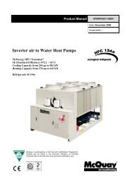
Space requirements<br />
<strong>McSmart</strong> units are air-<strong>cooled</strong>, hence it is important to observe the minimum distances which guarantee the<br />
best ventilation of the condenser coils. Limitations of space reducing the air flow could cause significant<br />
reductions in cooling capacity, <strong>and</strong> increase in electricity consumption. The fans do not allow the use of<br />
ducts which have high flow resistance, hence is should be ensured that the output air cannot recycle itself<br />
inside the condenser coils. The units should be positioned such that there is sufficient distance between the<br />
coils <strong>and</strong> any obstacles to improve ventilation <strong>and</strong> also to facilitate inspection (fig.1).<br />
When two or more units are positioned side by side it is recommended that the condenser coils are at least<br />
2<strong>500</strong>mm distance from one another (fig. 2). Smaller distances could cause the recirculation of hot air. If the<br />
units are positioned in places surrounded by walls or obstacles of the same height as the units, the units<br />
should be at least 2000mm from said obstacles (fig. 3). In the event the obstacles are higher than the units,<br />
the units should be at least 2<strong>500</strong>mm from the obstacle (fig. 4). For other installation solutions, consult<br />
McQuay technicians.<br />
101 B – 05/07 A – pag. 18/28
! "<br />
Dimensions<br />
<br />
<br />
<br />
<br />
<br />
<br />
<br />
<strong>McSmart</strong> C (mm) F (mm) G (mm)<br />
<strong>160</strong>÷190 1820 1000 1935<br />
210÷240 2056 1153 2185<br />
320 2750 1100 2180<br />
<br />
<br />
<br />
101 B – 05/07 A – pag. 19/28
! "<br />
Dimensions<br />
<br />
<br />
<br />
<br />
<br />
<strong>McSmart</strong> C (mm) F (mm) G (mm)<br />
400÷<strong>500</strong> 2750 2200 2180<br />
<br />
101 B – 05/07 A – pag. 20/28
! "<br />
Electrical connections<br />
General rules<br />
The <strong>chillers</strong> must be well grounded. It absolutely cannot be connected with gas-pipe, water pipe <strong>and</strong> telephone<br />
line.<br />
Ensure that the rated voltage of the unit corresponds to that of the name plate before general precautions.<br />
Provide a power outlet to be used exclusively for each unit. A power supply disconnects <strong>and</strong> a circuit breaker for<br />
over-current protection should be provided in the exclusive line.<br />
Electric wiring data for cooling only<br />
<strong>McSmart</strong> <strong>160</strong>C 190C 210C 240C 320C 400C <strong>500</strong>C<br />
Power<br />
400 V – 3ph + N – 50 Hz<br />
Power input (kW) Cooling 18,4 21,1 24,2 28,6 37,5 42,4 52,3<br />
Operation current (A) Cooling 32,8 36,7 43,2 50,1 69,8 76,7 100,5<br />
Power line<br />
Power<br />
line<br />
Line<br />
(R/S/T)<br />
Neutral Line<br />
Earth Line<br />
Section area<br />
(mm²)<br />
16 16 25 25 35 50 50<br />
number 3 3 3 3 3 3 3<br />
Section area<br />
(mm²)<br />
6 6 6 6 25 35 35<br />
number 1 1 1 1 1 1 1<br />
Section area<br />
(mm²)<br />
16 16 25 25 35 50 50<br />
number 1 1 1 1 1 1 1<br />
Every wire can not contact pipes, compressor, fan motor or other movable parts.<br />
Wires should be well connected.<br />
<br />
Electric wiring data for <strong>heat</strong> pump<br />
<strong>McSmart</strong> <strong>160</strong>CR 190CR 210CR 240CR 320CR 400CR <strong>500</strong>CR<br />
Power input (kW)<br />
Operation current (A)<br />
Power line<br />
Power<br />
line<br />
Power<br />
Line<br />
(R/S/T)<br />
Neutral Line<br />
Earth Line<br />
400 V – 3ph + N – 50 Hz<br />
Cooling 18,3 20,1 23,4 27,1 35,5 41,0 50,7<br />
Heating 19,5 20,7 25,6 28,5 38,1 45,4 57,3<br />
Cooling 32,6 35,8 41,9 49,7 66,1 74,2 97,4<br />
Heating 34,7 36,8 45,9 52,3 70,9 82,1 110,1<br />
Section area<br />
(mm²)<br />
16 16 25 25 35 50 50<br />
number 3 3 3 3 3 3 3<br />
Section area<br />
(mm²)<br />
6 6 6 6 25 35 35<br />
number 1 1 1 1 1 1 1<br />
Section area<br />
(mm²)<br />
4 4 4 4 35 50 50<br />
number 1 1 1 1 1 1 1<br />
Every wire can not contact pipes, compressor, fan motor or other movable parts.<br />
Wires should be well connected.<br />
101 B – 05/07 A – pag. 21/28
! "<br />
Water circuit<br />
General rules<br />
Be sure to use clean water when filling in the water circuit to avoid heavy corrosion <strong>and</strong> choking of the<br />
system. If the chiller is operated under very oily, salty or acidic atmosphere or water, these substances may<br />
lead to capacity drop or failure of the unit.<br />
Prior to starting up the unit, flushing of the water system is required.<br />
Water flow should not be lower that the nominal value of the unit.<br />
<br />
Water content in cooling circuits<br />
The <strong>cooled</strong> water distribution circuits should have a minimum water content to avoid excessive compressors<br />
start <strong>and</strong> stop.<br />
To prevent damage to the compressors, the controller limits frequent stops <strong>and</strong> restarts.<br />
During one hour there will be no more than 10 starts for each compressor. The plant side should therefore<br />
ensures that the overall water content allows more constant functioning of the unit <strong>and</strong> consequently greater<br />
environmental comfort. The minimum installation water content envisaged per unit should be calculated with<br />
a certain approximation using this simplified formula:<br />
(1) Q = 43<br />
P (kW) 1<br />
X<br />
∆T(<br />
° C) N<br />
where:<br />
Q = Minimum content per unit in litres<br />
P = Unit cooling capacity in kW<br />
N = reduction steps number<br />
∆T = temperature difference to be selected according to the following table<br />
Reduction steps number ∆T<br />
1 7,5<br />
2 5,0<br />
3 4,2<br />
4 4,0<br />
For more accurate calculation of water quantity, it is advisable to contact the designer of the plant.<br />
101 B – 05/07 A – pag. 22/28
! "<br />
Evaporator pressure drops<br />
<strong>McSmart</strong> <strong>160</strong>÷<strong>500</strong> C / CR<br />
Pressure drop (kPa)<br />
100<br />
90<br />
80<br />
70<br />
60<br />
50<br />
40<br />
30<br />
20<br />
10<br />
0<br />
<strong>500</strong><br />
<strong>160</strong> 320<br />
190÷210 240<br />
400<br />
1 2 3 4 5 6 7 8<br />
W ater flow (l/s)<br />
101 B – 05/07 A – pag. 23/28
! "<br />
Water pump available lift<br />
450<br />
400<br />
Available head (kPa)<br />
350<br />
300<br />
250<br />
200<br />
150<br />
100<br />
50<br />
0<br />
400<br />
240<br />
210<br />
190<br />
320<br />
<strong>500</strong><br />
<strong>160</strong><br />
0,5 1,0 1,5 2,0 2,5 3,0 3,5 4,0 4,5 5,0 5,5 6,0 6,5 7,0 7,5<br />
Water flow (l/s)<br />
Pumps data<br />
<strong>McSmart</strong> Power input (kW) AMPS IP Power supply<br />
<strong>160</strong> 0,75 2,00 54 400V/3ph/50Hz<br />
190÷210 1,10 2,80 54 400V/3ph/50Hz<br />
240÷320 1,85 4,95 54 400V/3ph/50Hz<br />
400 2,50 5,85 54 400V/3ph/50Hz<br />
<strong>500</strong> 3,00 6,10 55 400V/3ph/50Hz<br />
101 B – 05/07 A – pag. 24/28
General rules<br />
Maintenance is of extreme importance if the plant is to operate in a regular way <strong>and</strong> give fade-free service.<br />
Have extraordinary maintenance work done by qualified <strong>and</strong> authorized personnel. Comply with the safety<br />
precautions given in the relative section of this manual <strong>and</strong> take all the necessary precautions.<br />
The following information is only a guide for the end user.<br />
<br />
Routine maintenance<br />
The inspections described below to which the unit must be subjected do not require specific technical knowhow.<br />
They merely include a few simple checks involving certain parts of the unit.<br />
Call an authorized assistance centre if actual maintenance work is required.<br />
The table below gives a recommended list of inspections which should be carried out at the indicated<br />
frequencies.<br />
DESCRIPTION WEEKLY MONTHLY EVERY SIX MONTHS<br />
Visual inspection of the structure of the unit<br />
<br />
Inspection of the hydraulic circuit<br />
<br />
Inspection of the electrical system<br />
<br />
Inspection of the condensing section<br />
<br />
Reading <strong>and</strong> recording of operating parameters <br />
<br />
Visual inspection of the structure of the unit<br />
When checking the condition of the parts that form the structure of the unit, pay particular attention to the<br />
parts liable to rust. If traces of rust are noted, they must be treated with rust-inhibitor paint in order to<br />
eliminate or reduce the problem. Check to make sure that the external panels of the unit are well fixed.<br />
Bad fixing gives rise to noise to noise <strong>and</strong> abnormal vibrations.<br />
<br />
Inspection of the hydraulic circuit<br />
Check visually to make sure that there are no leaks in the hydraulic circuit. And the water filter is clean.<br />
<br />
Inspection of the electrical system<br />
Make sure that the power cable that connects the unit to the distribution panel is not torn, cracked or<br />
damaged in a way that could impair its insulation.<br />
<br />
Inspection of the condensing section<br />
<br />
WARNING: The finned pack exchanger has fins made of aluminium, thus even accidental contact could<br />
cause cuts. Comply with the instructions in the relative section.<br />
<br />
Condensing bank<br />
In view of the function of this component, it is very important for the surface of the exchanger to be as free as<br />
possible from clogging caused by items that could reduce the air flow rate of the fan <strong>and</strong>, thus, the<br />
performances of the unit itself. The following operations may be required:<br />
Remove all impurities (such as paper scraps, leaves, etc., etc.)that could be clogging the surface of the bank<br />
either by h<strong>and</strong> or using a brush (comply with the above mentioned safety prescriptions).<br />
If the dirt has deposited on the fins <strong>and</strong> is difficult to remove by h<strong>and</strong>, use a jet of compressed air or<br />
pressurized water in the aluminium bank surface, remembering to direct the jet in a vertical direction to<br />
prevent the fins from being damaged.<br />
“Comb ”the bank with the relative tool, using the appropriate comb spacing for the fins if some parts of thwm<br />
are bent or squashed.<br />
Helical electric fans<br />
Visually inspect these parts to make sure that the electric fans are well fixed to the bearing grille <strong>and</strong> that this<br />
latter is fixed to the structure of the unit. Bad fixing leads to noise <strong>and</strong> abnormal vibrations.<br />
<br />
101 B – 05/07 A – pag. 25/28
%*<br />
The machine has been designed to reduce risks to persons <strong>and</strong> to the environment in which it is installed, to<br />
the minimum. To eliminate residue hazards, it is therefore advisable to become as familiar as possible with<br />
the machine in order to avoid accidents that could cause injuries to persons <strong>and</strong>/or damage to the property.<br />
a. Access to the unit<br />
Only qualified persons who are familiar with this type of machine <strong>and</strong> who are equipped with the necessary<br />
safety protections (footwear, gloves, helmet, etc.) may be allowed to access the machine. Moreover, in order<br />
to operate, these persons must have been authorized by the owner of the machine <strong>and</strong> be recognized by the<br />
Manufacturer itself.<br />
b. Elements of risk<br />
The machine has been designed <strong>and</strong> built so as not to create any condition of risk. However, residue<br />
hazards are impossible to eliminate during the planning phase are therefore listed in the following table along<br />
with the instructions on how to neutralize them.<br />
Part question Residue hazard Mode Precautions<br />
Compressor <strong>and</strong><br />
delivery pipe<br />
Burns<br />
Contact with the pipes<br />
<strong>and</strong>/or the compressor<br />
Pipes in general Ice burns Leaking coolant<br />
Heat<br />
bank<br />
exchange<br />
Avoid contact by wearing<br />
protective gloves<br />
Do not exercise tension on the<br />
pipes<br />
Cuts Contact Wear protective gloves<br />
Electric fans Cuts Contact with the skin<br />
Do not push the h<strong>and</strong>s or<br />
objects through the fan grille<br />
<br />
<br />
<br />
<br />
<br />
<br />
101 B – 05/07 A – pag. 26/28
101 B – 05/07 A – pag. 27/28
We reserve the right to make changes in design <strong>and</strong> construction at any time without notice, thus the cover picture is not binding.<br />
McQuay partecipa al programma di<br />
Certificazione Eurovent.<br />
I prodotti interessati figurano nella Guida<br />
Eurovent dei Prodotti Certificati.<br />
McQuay is participating in the Eurovent<br />
Certification Programme<br />
Product are as listed in the Eurovent<br />
Directory of Certified Products<br />
McQuay Italia S.P.A.<br />
S.S. Nettunense, km 12+300 – 00040 Cecchina (Roma) Italia – Tel. (06) 937311 – Fax (06) 9374014 – email: info@mcquayeurope.com<br />
www.mcquayeurope.com<br />
101 B – 05/07 A – pag. 28/28