Inverter Air cooled screw chillers - McQuay
Inverter Air cooled screw chillers - McQuay
Inverter Air cooled screw chillers - McQuay

You also want an ePaper? Increase the reach of your titles
YUMPU automatically turns print PDFs into web optimized ePapers that Google loves.
Product Manual<br />
511 B – 08/10 A<br />
Date: October 2008<br />
Supersedes: None<br />
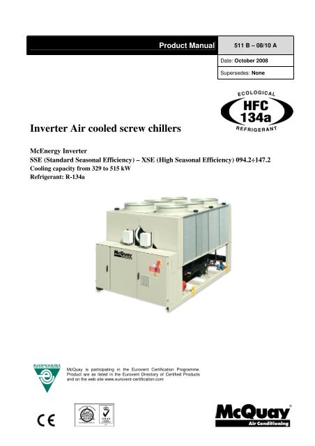
<strong>Inverter</strong> <strong>Air</strong> <strong>cooled</strong> <strong>screw</strong> <strong>chillers</strong><br />
McEnergy <strong>Inverter</strong><br />
SSE (Standard Seasonal Efficiency) – XSE (High Seasonal Efficiency) 094.2÷147.2<br />
Cooling capacity from 329 to 515 kW<br />
Refrigerant: R-134a<br />
<strong>McQuay</strong> is participating in the Eurovent Certification Programme.<br />
Product are as listed in the Eurovent Directory of Certified Products<br />
and on the web site www.eurovent-certification.com<br />
808 B – 07/11 A – pag. 1/52
Features and benefits<br />
High part load efficiency<br />
McEnergy Invert is the result of careful design, aimed to optimizing the seasonal energy efficiency of <strong>chillers</strong>,<br />
with the objective of bringing down operating costs and improving profitability, effectiveness and economical<br />
management.<br />
Per European Seasonal Energy Efficiency Ratio (ESSER), <strong>chillers</strong> operate at design conditions only three<br />
percent of the time. As a result better part load efficiencies are required at part load conditions in a chiller water<br />
applications. McEnergy <strong>Inverter</strong> maximize chiller efficiency by optimizing single <strong>screw</strong> compressor operation<br />
dramatically reducing the electric power consumption when the motor speed slows.<br />
Seasonal quietness<br />
Very low noise levels in part load conditions are achieved by varying the fan speed, but especially thanks to the<br />
variation of compressor frequency, which ensure the minimum noise level at all the time.<br />
Quick comfort conditions<br />
The ability to vary the output power in direct relation to the cooling requirements of the system, allow the<br />
possibility to achieve building comfort conditions much faster at start-up.<br />
Low starting current<br />
No current spikes at start-up. The starting current is always lower than current absorbed in the maximum<br />
operating conditions (FLA).<br />
Power factor always > 0.95<br />
McEnergy <strong>Inverter</strong> can operate always > 0.95 power factor, which can allows building owners avoid power<br />
factor penalties and decreases electrical losses in cable and transformers.<br />
Redundancy<br />
McEnergy <strong>Inverter</strong> has two truly independent refrigerant circuits in every size, in order to assure maximum<br />
safety for any maintenance, whether planned or not.<br />
Infinitely capacity control<br />
Cooling capacity control is infinitely variable by means of<br />
a <strong>Inverter</strong> driven <strong>screw</strong> compressor controlled by<br />
microprocessor system. Each unit has infinitely variable<br />
capacity control from 100% down to 27% (one<br />
compressor unit), down to 13,5% (two compressors<br />
units). This modulation allows the compressor capacity to<br />
exactly match the building cooling load without any<br />
leaving evaporator water temperature fluctuation. This<br />
chilled water temperature fluctuation is avoided only with<br />
a stepless control.<br />
With a compressor load step control in fact, the<br />
compressor capacity, at partial loads, will be too high or<br />
too low compared to the building cooling load. The result<br />
is an increase in chiller energy costs, particularly at the<br />
part-load conditions at which the chiller operates most of<br />
the time.<br />
Compressor Load<br />
Building Load<br />
time<br />
ELWT fluctuation with steps capacity control (4 steps)<br />
Compressor Load<br />
Building Load<br />
NO EWLT fluctuation with <strong>McQuay</strong> stepless capacity control (4 steps)<br />
Units with stepless regulation offer benefits that the units with step regulation are unable to match. The ability to<br />
follow the system energy demand at any time and the possibility to provide steady outlet water temperature<br />
without deviations from the set-point, are the two points that allow you to understand how the optimum operating<br />
conditions of a system can be met only through the use of a unit with step-less regulation.<br />
808 B – 07/11 A – pag. 2/52
Code requirements – Safety and observant of laws/directives<br />
All water <strong>cooled</strong> units are designed and manufactured in accordance with applicable selections of the following<br />
which are equivalent to American <strong>Air</strong>-conditioning industry applicable codes:<br />
Rating of <strong>chillers</strong> EN 12055<br />
Construction of pressure vessel Pressure Equipment 97/23/EC (PED)<br />
Machinery Directive<br />
98/37/EC<br />
Low Voltage<br />
2006/95/EC<br />
Electromagnetic Compatibility 2004/108/EC<br />
Electrical & Safety codes IEC 60204–1<br />
Manufacturing Quality Stds UNI – EN ISO 9001:2000<br />
Certifications<br />
All units manufactured by <strong>McQuay</strong> Italia S.p.A. are CE marked, complying with European directives in force,<br />
concerning manufacturing and safety. On request units can be produced complying with laws in force in non<br />
European countries (ASME, GOST, etc.), and with other applications, such as naval (RINA, etc.).<br />
Versions<br />
McEnergy <strong>Inverter</strong> is available in two different Seasonal Efficiency Versions:<br />
SSE: Standard Seasonal Efficiency<br />
7 sizes to cover a range from 329 up to 515 kW with an ESEER up to 4.62<br />
XSE: High Seasonal Efficiency<br />
7 sizes to cover a range from 329 up to 515 kW with an ESEER up to 5.01<br />
The ESEER (European Seasonal Energy Efficiency Ratio) is a weighed formula enabling to<br />
take into account the variation of EER with the load rate and the variation of air inlet<br />
condenser temperature.<br />
ESEER = A x EER 100% + B x EER 75% + C x EER 50% + D x EER 25%<br />
A B C D<br />
Coefficient 0.03 (3%) 0.33 (33%) 0.41 (41%) 0.23 (23%)<br />
<strong>Air</strong> inlet condenser temperature 35°C 30°C 25°C 20°C<br />
Noise Configuration<br />
McEnergy <strong>Inverter</strong> is available in many different Noise level configurations:<br />
ST: Standard Noise<br />
Condenser fan rotating at 700 rpm, rubber antivibration on compressor<br />
LN: Low Noise<br />
Condenser fan rotating at 700 rpm, rubber antivibration on compressor, sound proof<br />
cabinet for each compressor<br />
XN: Extra Low Noise (available only for XSE version)<br />
Condenser fan rotating at 700 rpm, rubber antivibration on compressor, one sound proof<br />
cabinet for compressor and evaporator, suction muffler<br />
808 B – 07/11 A – pag. 3/52
General characteristics<br />
Cabinet and structure<br />
The cabinet is made of galvanized steel sheet and painted to provide a high resistance to corrosion. The base<br />
frame has rings for lifting the unit with ropes for an easy installation. The weight is uniformly distributed along<br />
the profiles of the base and this facilitates the arrangement of the unit.<br />
Screw compressors with integrated oil separator<br />
The compressors are semi-hermetic, single-<strong>screw</strong> type with gate-rotor (made of carbon impregnated<br />
engineered composite material). Each compressor has one inverter managed by the unit microprocessor for<br />
infinitely modulating the capacity. An integrated high efficiency oil separator maximises the oil separation.<br />
Start is inverter type.<br />
Ecological HFC 134a refrigerant<br />
The compressors have been designed to operate with R-134a, ecological refrigerant with zero ODP (Ozone<br />
Depletion Potential) and very low GWP (Global Warming Potential) that means low TEWI (Total Equivalent<br />
Warming Impact).<br />
Evaporator<br />
The units are supplied with optimised shell and tubes evaporator pass that allows a perfect oil circulation and so<br />
a perfect oil return to the compressor. It is direct expansion with refrigerant inside the tubes and water outside<br />
(shell side) with carbon steel tube sheets, with straight copper tubes that are spirally wound internally for higher<br />
efficiencies, expanded on the tube plates. The external shell is covered with a 10mm closed cell insulation<br />
material. Each evaporator has 2 circuits, one for each compressor and is manufactured in accordance to PED<br />
approval. The evaporator water outlet connections are provided with Victaulic Kit.<br />
Condenser coils<br />
The condenser is manufactured with internally enhanced seamless copper tubes arranged in a staggered row<br />
pattern and mechanically expanded into <strong>McQuay</strong> lanced and rippled aluminium condenser fins with full fin<br />
collars. An integral sub-cooler circuit provides sub-cooling to effectively eliminate liquid flashing and increase in<br />
cooling capacity without increasing the power input.<br />
Condenser coil fans<br />
The condenser fans are helical type with wing-profile blades for achieving better performance. Each fan is<br />
protected by a guard. The motors are IP54. Fans thermal overload relays are supplied as standard.<br />
Electronic expansion valve<br />
The unit is equipped with the most advanced electronic expansion valves to achieve precise control of<br />
refrigerant mass flow. As today’s system requires improved energy efficiency, tighter temperature control, wider<br />
range of operating conditions and incorporate features like remote monitoring and diagnostics, the application of<br />
electronic expansion valves becomes mandatory. Electronic expansion valve proposes features that makes it<br />
unique: short opening and closing time, high resolution, positive shut-off function to eliminate use of additional<br />
solenoid valve, highly linear flow capacity, continuous modulation of mass flow without stress in the refrigerant<br />
circuit and corrosion resistance stainless steel body.<br />
EEXV strength point is the capacity to work with lower ∆P between high and low pressure side, than a<br />
thermostatic expansion valve. The electronic expansion valve allows the system to work with low condenser<br />
pressure (winter time) without any refrigerant flow problems and with a perfect chilled water leaving temperature<br />
control.<br />
Refrigerant Circuit<br />
Each unit has 2 independent refrigerant circuits and each one includes:<br />
• Compressor with integrated oil separator<br />
• Oil pressure transducer<br />
• High and pressure switches<br />
• High pressure transducer<br />
• Low pressure transducer<br />
• Moisture liquid indicator<br />
• High efficiency oil separator<br />
• Replaceable core filter-drier<br />
808 B – 07/11 A – pag. 4/52
• Electronic expansion valve<br />
• Suction line shut off valve<br />
• Discharge line shut off valve<br />
Electrical control panel<br />
Power and control are located in two sections of the main panel that is manufactured to ensure protection<br />
against all weather conditions. The power panel is fitted with an interlocked door main isolator to prevent access<br />
while power supply is on. Electrical panel is IP54.<br />
Power Section<br />
The power section includes circuit breaker, compressors inverters, fans contactors, fans thermal overload<br />
relays, fans inverter and control circuit transformer.<br />
MicroTech II C Plus controller<br />
MicroTech II C Plus controller is installed as standard; it can be used to modify unit set-points and check control<br />
parameters. A built-in display shows machine's operating status, programmable values, set-points, like<br />
temperatures and pressures of water, refrigerant and air. Device controls maximise the chiller energy efficiency<br />
and the reliability. A sophisticated software with predictive logic, select the most energy efficient combination of<br />
compressors, EEXV and condenser fans to keep stable operating conditions and maximise energy efficiency.<br />
The compressors are automatically rotated to ensure equal operating hours. MicroTech II C Plus protects critical<br />
components in response to external signals from its system sensors measuring: motor temperatures, refrigerant<br />
gas and oil pressures, correct phase sequence and evaporator.<br />
Control section - main features<br />
• Management of the compressor capacity, <strong>Inverter</strong>, slide and fans modulation.<br />
• Chillers enabled to work in partial failure condition.<br />
• Full routine operation at condition of:<br />
- high ambient temperature value,<br />
- high thermal load,<br />
- high evaporator entering water temperature (start-up).<br />
• Display of evaporator entering/leaving water temperature.<br />
• Display of condensing-evaporating temperature and pressure, suction and discharge superheat for each<br />
circuit.<br />
• Leaving water <strong>cooled</strong> temperature regulation. Temperature tolerance = 0,1°C.<br />
• Compressors and evaporator pumps hours counter.<br />
• Display of Status Safety Devices.<br />
• Start up numbers and compressors working hours equalization.<br />
• Optimized management of compressors load.<br />
• Fans management according to condensing pressure.<br />
• Automatic re-start in case of power supply interruption (adjustable).<br />
• Soft Load.<br />
• Start at high evaporator water temperature.<br />
• Return Reset.<br />
• AOT Reset (optional).<br />
• Set point Reset (optional).<br />
Safety for each refrigerant circuit<br />
• High pressure (pressure switch).<br />
• Low pressure (transducer).<br />
• Condensation fan Magneto-thermal.<br />
• High Discharge Temperature on the compressor.<br />
• Phase Monitor.<br />
• Low pressure ratio.<br />
808 B – 07/11 A – pag. 5/52
• High oil pressure drop.<br />
• Low oil pressure.<br />
System security<br />
• Phase monitor.<br />
• Freeze protection.<br />
Regulation type<br />
Proportional + integral + derivative regulation on the leaving water evaporator output probe.<br />
Condensation<br />
The condensation can be carried out according to temperature or pressure or pressure ratio. The fans can be<br />
managed according to a 0/10 V modulating signal.<br />
Intelligent Compressor Start Mode<br />
Control software includes an intelligent compressor start mode that unloads the first compressor to 75% during<br />
the start of the second one, in order to reduce inrush current.<br />
MicroTech II C Plus terminal<br />
MicroTech II C Plus built-in terminal has the following features.<br />
• 4-lines by 20-character liquid crystal display back lighting.<br />
• Key-pad consisting of 6 keys.<br />
• Memory to protect the data.<br />
• General faults alarm relays.<br />
• Password access to modify the setting.<br />
• Service report displaying all running hours and general conditions.<br />
• Alarm history memory to allow an easy fault analysis.<br />
Standard accessories (supplied on basic unit)<br />
Double set-point – Dual leaving water temperature set-points.<br />
Fans thermal overload relays – Safety devices against fan motor overloading in addition to the normal<br />
protection envisaged by the electrical windings.<br />
Phase monitor – The phase monitor controls that phases sequence is correct and controls phase loss.<br />
<strong>Inverter</strong> starter – For low inrush current and reduced starting torque.<br />
Victaulic evaporator water connection – Hydraulic joint with gasket for an easy and quick water connection.<br />
Evaporator electric heater – Electric heater controlled by a thermostat to protect the evaporator from freezing<br />
down to -28°C ambient temperature, providing the power supply is on.<br />
Electronic Expansion Valve.<br />
Discharge line shut off valves – Installed on the discharge port of the compressor.<br />
Suction line shut off valve – Suction shut-off valve installed on the suction port of the compressor to facilitate<br />
maintenance operation.<br />
Low pressure manometers.<br />
Hour run meter.<br />
General fault relay – Contactor for alarm warning.<br />
808 B – 07/11 A – pag. 6/52
Options (on request)<br />
Total heat recovery – Produced with shell and tube heat exchangers to produce hot water up to +55° C. The<br />
heat exchangers are mounted on the refrigerant circuits parallel to the condenser coils to remove all the<br />
condensation heat.<br />
Partial heat recovery – Produced with plate to plate heat exchangers installed between the compressor<br />
discharge and the condenser coil. These allow hot water to be produced up to a maximum temperature of 55°C.<br />
Brine version – Set-point can go down to -8°C.<br />
20mm insulation on evaporator.<br />
Condenser coil guards<br />
Cu-Cu condensing coils - To give better protection against corrosion by aggressive environments.<br />
Cu-Cu-Sn condensing coils - To give better protection against corrosion in aggressive environments and by<br />
salty air.<br />
Alucoat condensing coils - Fins are protected by a special acrylic paint with a high resistance to corrosion.<br />
Hydronic Kit (one water circulation pump – low or high lift) – Hydronic kit consists of: one centrifugal pump<br />
direct driven, expansion vessel water feed circuit with pressure gauge, safety valve. The pump motor is<br />
protected by a circuit breaker installed in control panel. The kit is assembled and wired to the control panel.<br />
Hydronic kit (two water circulation pumps – low or high lift) – Hydronic kit consists of: two centrifugal<br />
pumps direct driven, expansion vessel, water feed circuit with pressure gauge, safety valve. The pumps motors<br />
are protected by circuit breakers installed in control panel. The kit is assembled and wired to the control panel.<br />
Under/Over Voltage – This device control the voltage value and stop the chiller when this exceeds limits set by<br />
customer.<br />
Current limit display<br />
Evaporator Flow switch - Supplied separately to be wired and installed on the evaporator water piping (by the<br />
customer).<br />
High pressure manometers.<br />
Set-point reset and demand limit and alarm from external device.<br />
Ambient outside temperature sensor and set-point reset.<br />
Rubber type antivibration mounts - Supplied separately, these are positioned under the base of the unit<br />
during installation. Ideal to reduce the vibrations when the unit is floor mounted.<br />
Spring type antivibration mounts - Supplied separately, these are positioned under the base of the unit<br />
during installation. Ideal for dampening vibrations for installation on roofs and metallic structures.<br />
Inertial tank with cabinet ( 500 l or 1000 l ) – Piping to unit are not included and electric heater power supply<br />
has to be provided from external source.<br />
Witness tests - Every unit is always tested at the test bench prior to the shipment. On request, a second test<br />
can be carried out, at customer’s presence, in accordance with the procedures indicated on the test form. (Not<br />
available for units with glycol mixtures).<br />
Acoustic test.<br />
808 B – 07/11 A – pag. 7/52
Supervising systems (on request)<br />
PlantVisor TM :<br />
Solution for tele-maintenance and supervisory<br />
MicroTech II C Plus can be monitored locally or via modem or GSM by PlantVisor TM supervision program.<br />
PlantVisorTM is compatible with all Windows based systems.<br />
It allows the followings functions:<br />
• Unit status monitoring<br />
• Circuits status monitoring<br />
• Set-points modification<br />
• Alarms display.<br />
MicroTech II C Plus remote control<br />
MicroTech II C Plus is able to communicate to BMS (Building Management System) based on the most<br />
common protocols as:<br />
• CARELNative<br />
• ModbusRTU<br />
• LonWorks, now also based on the international 8040 Standard Chiller Profile and LonMark Technology<br />
• BacNet BTP certifief over IP and MS/TP (class 4)<br />
• Ethernet TCP/IP and SNM.<br />
Chiller Sequencing<br />
MicroTech II control family allows an easy plug-in sequencing technology based on digital or serial field panel<br />
MCS (<strong>McQuay</strong> Chiller Sequences)<br />
Digital Step <strong>Inverter</strong> to sequence and rotate up to 11 <strong>chillers</strong>, based on 1 or 2 configurable input sensors. A very<br />
interesting low level full configurable digital field system. Monitorable by Plant Visor.<br />
CSC III (Chiller System Controller III)<br />
Serial sequences for up to 6 <strong>chillers</strong>. Full featured field serial device to sequence, optimize and monitor a little<br />
group of <strong>McQuay</strong> <strong>chillers</strong>. Monitorable by Plant Visor.<br />
808 B – 07/11 A – pag. 8/52
Nomenclature<br />
McEnergy <strong>Inverter</strong> <strong>Air</strong> <strong>cooled</strong> <strong>screw</strong> chiller<br />
McEnergy <strong>Inverter</strong> XSE 094 .2 ST 134<br />
SSE<br />
XSE<br />
Standard Seasonal Efficiency<br />
High Seasonal Efficiency<br />
094.2 ÷ 147.2 Unit size<br />
2 N° of compressors<br />
ST<br />
LN<br />
XN<br />
Standard Noise version<br />
Low Noise version<br />
Extra Low Noise version<br />
134 Refrigerant R 134A<br />
808 B – 07/11 A – pag. 9/52
Specifications<br />
TECHNICAL SPECIFICATIONS Version SSE 94.2 102.2 113.2 122.2<br />
Capacity Cooling 329 358 395 423<br />
Capacity control<br />
Type<br />
Stepless<br />
Minimum capacity % 13.5% 13.5% 13.5% 13.5%<br />
Unit power input Cooling kW 120 136 147 159<br />
EER 2,74 2,63 2,68 2,66<br />
ESEER 4,59 4,60 4,55 4,59<br />
Casing<br />
Colour<br />
RAL7032<br />
Material<br />
Galvanized and painted steel sheet<br />
Height mm 2355 2355 2355 2355<br />
Dimensions Unit<br />
Width mm 2224 2224 2224 2224<br />
Depth mm 4352 4352 5252 5252<br />
Weight ST<br />
Unit kg 4190 4190 4590 4590<br />
Operating Weight kg 4440 4440 4840 4840<br />
Weight LN<br />
Unit Kg 4340 4340 4740 4740<br />
Operating Weight kg 4590 4590 4990 4990<br />
Type<br />
Single Pass Shell&Tube<br />
Water volume l 271 264 264 256<br />
Water heat<br />
Nominal water<br />
Cooling l/min 943 1026 1132 1213<br />
exchanger<br />
flow rate<br />
Nominal Water<br />
Cooling kPa 60 61 72 67<br />
pressure drop<br />
Insulation material<br />
Closed cell foam elastomer<br />
<strong>Air</strong> heat exchanger Type Louvered fins<br />
Type<br />
Axial<br />
Drive<br />
VFD driven<br />
Diameter mm 800 800 800 800<br />
Fan<br />
Nominal air flow m³/min 1960 1960 2450 2450<br />
Quantity 8 8 10 10<br />
Model<br />
Speed in cooling rpm 700 700 700 700<br />
Motor output in cool. W 1133 1133 1133 1133<br />
Semi-hermetic<br />
Type<br />
single <strong>screw</strong> compressor<br />
Compressor<br />
Oil charge l 26 26 26 26<br />
Quantity 2 2 2 2<br />
Sound level (ST)<br />
Sound Power Cooling dBA 102,8 102,8 103,2 103,2<br />
Sound Pressure Cooling dBA 83,0 83,0 83,0 83,0<br />
Sound level (LN)<br />
Sound Power Cooling dBA 96,9 96,9 97,3 97,3<br />
Sound Pressure Cooling dBA 77,0 77,0 77,0 77,0<br />
Refrigerant type R-134a R-134a R-134a R-134a<br />
Refrigerant circuit Refrigerant charge kg 80 80 100 100<br />
N. of circuits 2 2 2 2<br />
Piping connections Evaporator water inlet/outlet 168,3 168,3 168,3 168,3<br />
Safety devices High discharge pressure (pressure switch)<br />
Safety devices High discharge pressure (transducer)<br />
Safety devices Low suction pressure (transducer)<br />
Safety devices Compressor overload (Kriwan)<br />
Safety devices High discharge temperature<br />
Safety devices Low oil pressure<br />
Safety devices Low pressure ratio<br />
Safety devices High oil pressure drop<br />
Safety devices Phase monitor<br />
Safety devices Emergency stop<br />
Notes<br />
Cooling capacity, unit power input in cooling and EER are based on the following conditions:<br />
evaporator 12°C/7°C; ambient 35°C.<br />
808 B – 07/11 A – pag. 10/52
TECHNICAL SPECIFICATIONS Version SSE 131.2 139.2 147.2<br />
Capacity Cooling kW 459 488 515<br />
Capacity control<br />
Type<br />
Stepless<br />
Minimum capacity % 13.5% 13.5% 13.5%<br />
Unit power input Cooling kW 168 181 193<br />
EER 2,74 2,71 2,67<br />
ESEER 4,57 4,70 4,60<br />
Casing<br />
Colour<br />
RAL7032<br />
Material<br />
Galvanized and painted steel sheet<br />
Height mm 2355 2355 2355<br />
Dimensions Unit<br />
Width mm 2224 2224 2224<br />
Depth mm 6152 6152 6152<br />
Weight ST<br />
Unit kg 5070 5070 5070<br />
Operating Weight kg 5320 5320 5320<br />
Weight LN<br />
Unit Kg 5220 5220 5220<br />
Operating Weight kg 5470 5470 5470<br />
Type<br />
Single Pass Shell&Tube<br />
Water volume l 256 248 248<br />
Water heat<br />
Nominal water<br />
Cooling l/min 1316 1399 1476<br />
exchanger<br />
flow rate<br />
Nominal Water<br />
Cooling kPa 78 69 76<br />
pressure drop<br />
Insulation material<br />
Closed cell foam elastomer<br />
<strong>Air</strong> heat exchanger Type Louvered fins<br />
Type<br />
Axial<br />
Drive<br />
VFD driven<br />
Diameter mm 800 800 800<br />
Fan<br />
Nominal air flow m³/min 2940 2940 2940<br />
Quantity 12 12 12<br />
Model<br />
Speed in cooling rpm 700 700 700<br />
Motor output in cool. W 1133 1133 1133<br />
Semi-hermetic<br />
Type<br />
single <strong>screw</strong> compressor<br />
Compressor<br />
Oil charge l 26 26 26<br />
Quantity 2 2 2<br />
Sound level (ST)<br />
Sound Power Cooling dBA 103,6 103,6 103,6<br />
Sound Pressure Cooling dBA 83,5 83,5 83,5<br />
Sound level (LN)<br />
Sound Power Cooling dBA 98,2 98,2 98,2<br />
Sound Pressure Cooling dBA 77,5 77,5 77,5<br />
Refrigerant type R-134a R-134a R-134a<br />
Refrigerant circuit Refrigerant charge kg 120 120 120<br />
N. of circuits 2 2 2<br />
Piping connections Evaporator water inlet/outlet 168.3 168.3 168.3<br />
Safety devices High discharge pressure (pressure switch)<br />
Safety devices High discharge pressure (transducer)<br />
Safety devices Low suction pressure (transducer)<br />
Safety devices Compressor overload (Kriwan)<br />
Safety devices High discharge temperature<br />
Safety devices Low oil pressure<br />
Safety devices Low pressure ratio<br />
Safety devices High oil pressure drop<br />
Safety devices Phase monitor<br />
Safety devices Emergency stop<br />
Notes<br />
Cooling capacity, unit power input in cooling and EER are based on the following<br />
conditions: evaporator 12°C/7°C; ambient 35°C.<br />
808 B – 07/11 A – pag. 11/52
ELECTRICAL SPECIFICATIONS Version SSE 94.2 102.2 113.2 122.2<br />
Phase 3 3 3 3<br />
Frequency Hz 50 50 50 50<br />
Power Supply Voltage V 400 400 400 400<br />
Voltage Tolerance<br />
Minimum % -10% -10% -10% -10%<br />
Maximum % +10% +10% +10% +10%<br />
Maximum starting current A 232 250 251 278<br />
Nominal running current cooling A 194 220 239 258<br />
Unit<br />
Maximum running current A 322 322 328 358<br />
Maximum current for wires sizing A 355 355 361 394<br />
Min displacement power factor at nominal<br />
conditions<br />
0,98 0,98 0,98 0,98<br />
Fans Nominal running current in cooling A 22,4 22,4 28,0 28,0<br />
Phase 3 3 3 3<br />
Voltage V 400 400 400 400<br />
Compressor Voltage Tolerance<br />
Minimum % -10% -10% -10% -10%<br />
Maximum % +10% +10% +10% +10%<br />
Maximum running current A 150+150 150+150 150+150 150+150<br />
Starting method<br />
<strong>Inverter</strong><br />
ELECTRICAL SPECIFICATIONS Version SSE 131.2 139.2 147.2<br />
Phase 3 3 3<br />
Frequency Hz 50 50 50<br />
Power Supply Voltage V 400 400 400<br />
Voltage Tolerance<br />
Minimum % -10% -10% -10%<br />
Maximum % +10% +10% +10%<br />
Maximum starting current A 297 311 316<br />
Nominal running current cooling A 273 292 312<br />
Unit<br />
Maximum running current A 394 394 394<br />
Maximum current for wires sizing A 433 433 433<br />
Min displacement power factor at nominal<br />
conditions<br />
0,98 0,98 0,98<br />
Fans Nominal running current in cooling A 33,6 33,6 33,6<br />
Phase 3 3 3<br />
Voltage V 400 400 400<br />
Compressor Voltage Tolerance<br />
Minimum % -10% -10% -10%<br />
Maximum % +10% +10% +10%<br />
Maximum running current A 180+180 180+180 180+180<br />
Starting method<br />
<strong>Inverter</strong><br />
Notes<br />
Allowed voltage tolerance ± 10%. Voltage unbalance between phases must be within ± 3%.<br />
Maximum starting current: starting current of biggest compressor + 75% of maximum current of<br />
the other compressor + fans current for the circuit at 75%.<br />
Maximum starting current referred to installation with 25kA short circuit current<br />
Nominal current in cooling mode is referred to installation with 25kA short circuit current and is<br />
based on the following conditions: evaporator 12°C/7°C; ambient 35°C; compressors + fans<br />
current.<br />
Maximum Running Current is referred to installation with 25kA short circuit and is based on<br />
max compressor absorbed current in its envelope<br />
Maximum unit current for wires sizing is referred to installation with 25kA short circuit current<br />
and is based on minimum allowed voltage<br />
Maximum current for wires sizing: (compressors full load ampere + fans current) x 1,1.<br />
Minimum displacement power factor is referred to installation with 25kA short circuit<br />
808 B – 07/11 A – pag. 12/52
TECHNICAL SPECIFICATIONS Version XSE 94.2 102.2 113.2 122.2<br />
Capacity Cooling 329 358 395 423<br />
Capacity control<br />
Type<br />
Stepless<br />
Minimum capacity % 13.5% 13.5% 13.5% 13.5%<br />
Unit power input Cooling kW 118 135 145 157<br />
EER 2,78 2,66 2,73 2,70<br />
ESEER 4,79 4,82 4,78 4,84<br />
Casing<br />
Colour<br />
RAL7032<br />
Material<br />
Galvanized and painted steel sheet<br />
Height mm 2355 2355 2355 2355<br />
Dimensions Unit<br />
Width mm 2224 2224 2224 2224<br />
Depth mm 4352 4352 5252 5252<br />
Weight ST<br />
Unit kg 4190 4190 4590 4590<br />
Operating Weight kg 4440 4440 4840 4840<br />
Weight LN<br />
Unit Kg 4340 4340 4740 4740<br />
Operating Weight Kg 4590 4590 4990 4990<br />
Weight XN<br />
Unit Kg 4390 4390 4790 4790<br />
Operating Weight kg 4640 4640 5040 5040<br />
Type<br />
Single Pass Shell&Tube<br />
Water volume l 271 264 264 256<br />
Water heat<br />
Nominal water<br />
Cooling l/min 943 1026 1132 1213<br />
exchanger<br />
flow rate<br />
Nominal Water<br />
Cooling kPa 60 61 72 67<br />
pressure drop<br />
Insulation material<br />
Closed cell foam elastomer<br />
<strong>Air</strong> heat exchanger Type Louvered fins<br />
Type<br />
Axial<br />
Drive<br />
DC <strong>Inverter</strong> (Brushless)<br />
Diameter mm 800 800 800 800<br />
Fan<br />
Nominal air flow m³/min 1960 1960 2450 2450<br />
Quantity 8 8 10 10<br />
Model<br />
Speed in cooling rpm 700 700 700 700<br />
Motor output in cool. W 900 900 900 900<br />
Semi-hermetic<br />
Type<br />
single <strong>screw</strong> compressor<br />
Compressor<br />
Oil charge l 26 26 26 26<br />
Quantity 2 2 2 2<br />
Sound level (ST)<br />
Sound Power Cooling dBA 102,8 102,8 103,2 103,2<br />
Sound Pressure Cooling dBA 83,0 83,0 83,0 83,0<br />
Sound level (LN)<br />
Sound Power Cooling dBA 96,9 96,9 97,3 97,3<br />
Sound Pressure Cooling dBA 77,0 77,0 77,0 77,0<br />
Sound level (XN)<br />
Sound Power Cooling dBA 92,9 92,9 93,3 93,3<br />
Sound Pressure Cooling dBA 73,0 73,0 73,0 73,0<br />
Refrigerant type R-134a R-134a R-134a R-134a<br />
Refrigerant circuit Refrigerant charge kg 80 80 100 100<br />
N. of circuits 2 2 2 2<br />
Piping connections Evaporator water inlet/outlet 168.3 168.3 168.3 168.3<br />
Safety devices High discharge pressure (pressure switch)<br />
Safety devices High discharge pressure (transducer)<br />
Safety devices Low suction pressure (transducer)<br />
Safety devices Compressor overload (Kriwan)<br />
Safety devices High discharge temperature<br />
Safety devices Low oil pressure<br />
Safety devices Low pressure ratio<br />
Safety devices High oil pressure drop<br />
Safety devices Phase monitor<br />
Safety devices Emergency stop<br />
Notes<br />
Cooling capacity, unit power input in cooling and EER are based on the following conditions:<br />
evaporator 12°C/7°C; ambient 35°C.<br />
808 B – 07/11 A – pag. 13/52
TECHNICAL SPECIFICATIONS Version XSE 131.2 139.2 147.2<br />
Capacity Cooling kW 459 488 515<br />
Capacity control<br />
Type<br />
Stepless<br />
Minimum capacity % 13.5% 13.5% 13.5%<br />
Unit power input Cooling kW 165 178 190<br />
EER 2,79 2,75 2,71<br />
ESEER 4,81 5,01 4,84<br />
Casing<br />
Colour<br />
RAL7032<br />
Material<br />
Galvanized and painted steel sheet<br />
Height mm 2355 2355 2355<br />
Dimensions Unit<br />
Width mm 2224 2224 2224<br />
Depth mm 6152 6152 6152<br />
Weight ST<br />
Unit kg 5070 5070 5070<br />
Operating Weight kg 5320 5320 5320<br />
Weight LN<br />
Unit Kg 5220 5220 5220<br />
Operating Weight Kg 5470 5470 5470<br />
Weight XN<br />
Unit Kg 5270 5270 5270<br />
Operating Weight kg 5520 5520 5520<br />
Type<br />
Single Pass Shell&Tube<br />
Water volume l 256 248 248<br />
Water heat<br />
Nominal water<br />
Cooling l/min 1316 1399 1476<br />
exchanger<br />
flow rate<br />
Nominal Water<br />
Cooling kPa 78 69 76<br />
pressure drop<br />
Insulation material<br />
Closed cell foam elastomer<br />
<strong>Air</strong> heat exchanger Type Louvered fins<br />
Type<br />
Axial<br />
Drive<br />
DC <strong>Inverter</strong> (Brushless)<br />
Diameter mm 800 800 800<br />
Fan<br />
Nominal air flow m³/min 2940 2940 2940<br />
Quantity 12 12 12<br />
Model<br />
Speed in cooling rpm 700 700 700<br />
Motor output in cool. W 900 900 900<br />
Semi-hermetic<br />
Type<br />
single <strong>screw</strong> compressor<br />
Compressor<br />
Oil charge l 26 26 26<br />
Quantity 2 2 2<br />
Sound level (ST)<br />
Sound Power Cooling dBA 103,6 103,6 103,6<br />
Sound Pressure Cooling dBA 83,5 83,5 83,5<br />
Sound level (LN)<br />
Sound Power Cooling dBA 98,2 98,2 98,2<br />
Sound Pressure Cooling dBA 77,5 77,5 77,5<br />
Sound level (XN)<br />
Sound Power Cooling dBA 94,2 94,2 94,2<br />
Sound Pressure Cooling dBA 73,5 73,5 73,5<br />
Refrigerant type R-134a R-134a R-134a<br />
Refrigerant circuit Refrigerant charge kg 120 120 120<br />
N. of circuits 2 2 2<br />
Piping connections Evaporator water inlet/outlet 168.3 168.3 168.3<br />
Safety devices High discharge pressure (pressure switch)<br />
Safety devices High discharge pressure (transducer)<br />
Safety devices Low suction pressure (transducer)<br />
Safety devices Compressor overload (Kriwan)<br />
Safety devices High discharge temperature<br />
Safety devices Low oil pressure<br />
Safety devices Low pressure ratio<br />
Safety devices High oil pressure drop<br />
Safety devices Phase monitor<br />
Safety devices Emergency stop<br />
Notes<br />
Cooling capacity, unit power input in cooling and EER are based on the following<br />
conditions: evaporator 12°C/7°C; ambient 35°C.<br />
808 B – 07/11 A – pag. 14/52
ELECTRICAL SPECIFICATIONS Version XSE 94.2 102.2 113.2 122.2<br />
Phase 3 3 3 3<br />
Frequency Hz 50 50 50 50<br />
Power Supply Voltage V 400 400 400 400<br />
Voltage Tolerance<br />
Minimum % -10% -10% -10% -10%<br />
Maximum % +10% +10% +10% +10%<br />
Maximum starting current A 232 244 251 278<br />
Unit<br />
Nominal running current cooling A 183 209 225 244<br />
Maximum running current A 311 311 314 344<br />
Maximum current for wires sizing A 342 342 345 378<br />
Fans Nominal running current in cooling A 11.2 11.2 14.0 14.0<br />
Phase 3 3 3 3<br />
Voltage V 400 400 400 400<br />
Compressor Voltage Tolerance<br />
Minimum % -10% -10% -10% -10%<br />
Maximum % +10% +10% +10% +10%<br />
Maximum running current A 150+150 150+150 150+150 150+150<br />
Starting method<br />
<strong>Inverter</strong><br />
ELECTRICAL SPECIFICATIONS Version XSE 131.2 139.2 147.2<br />
Phase 3 3 3<br />
Frequency Hz 50 50 50<br />
Power Supply Voltage V 400 400 400<br />
Voltage Tolerance<br />
Minimum % -10% -10% -10%<br />
Maximum % +10% +10% +10%<br />
Maximum starting current A 297 302 316<br />
Unit<br />
Nominal running current cooling A 256 275 295<br />
Maximum running current A 377 377 377<br />
Maximum current for wires sizing A 414 414 414<br />
Fans Nominal running current in cooling A 33.6 33.6 33.6<br />
Phase 3 3 3<br />
Voltage V 400 400 400<br />
Compressor Voltage Tolerance<br />
Minimum % -10% -10% -10%<br />
Maximum % +10% +10% +10%<br />
Maximum running current A 180+180 180+180 180+180<br />
Starting method<br />
<strong>Inverter</strong><br />
Notes<br />
Allowed voltage tolerance ± 10%. Voltage unbalance between phases must be within ± 3%.<br />
Maximum starting current: starting current of biggest compressor + 75% of maximum current of<br />
the other compressor + fans current for the circuit at 75%.<br />
Maximum starting current referred to installation with 25kA short circuit current<br />
Nominal current in cooling mode is referred to installation with 25kA short circuit current and is<br />
based on the following conditions: evaporator 12°C/7°C; ambient 35°C; compressors + fans<br />
current.<br />
Maximum Running Current is referred to installation with 25kA short circuit and is based on<br />
max compressor absorbed current in its envelope<br />
Maximum unit current for wires sizing is referred to installation with 25kA short circuit current<br />
and is based on minimum allowed voltage<br />
Maximum current for wires sizing: (compressors full load ampere + fans current) x 1,1.<br />
Minimum displacement power factor is referred to installation with 25kA short circuit<br />
808 B – 07/11 A – pag. 15/52
Sound pressure level<br />
McEnergy <strong>Inverter</strong> SSE / XSE - ST<br />
Unit Sound pressure level at 1 m from the unit in semispheric free field (rif. 2 x 10 -5 Pa) Power<br />
size 63 Hz 125 Hz 250 Hz 500 Hz 1000 Hz 2000 Hz 4000 Hz 8000 Hz dB(A) dB(A)<br />
94.2 79.1 77.8 79.0 77.6 80.0 76.1 65.6 56.6 83.0 102.8<br />
102.2 79.1 77.8 79.0 77.6 80.0 76.1 65.6 56.6 83.0 102.8<br />
113.2 79.1 77.8 79.0 77.6 80.0 76.1 65.6 56.6 83.0 103.2<br />
122.2 79.1 77.8 79.0 77.6 80.0 76.1 65.6 56.6 83.0 103.2<br />
131.2 79.6 78.3 79.5 78.1 80.6 76.6 65.6 56.6 83.5 103.6<br />
139.2 79.6 78.3 79.5 78.1 80.6 76.6 65.6 56.6 83.5 103.6<br />
147.2 79.6 78.3 79.5 78.1 80.6 76.6 65.6 56.6 83.5 103.6<br />
Note: The values are according to ISO 3744 and are referred to: evaporator 12/7° C, air ambient 35° C, full load operation.<br />
McEnergy <strong>Inverter</strong> SSE / XSE - LN<br />
Unit Sound pressure level at 1 m from the unit in semispheric free field (rif. 2 x 10 -5 Pa) Power<br />
size 63 Hz 125 Hz 250 Hz 500 Hz 1000 Hz 2000 Hz 4000 Hz 8000 Hz dB(A) dB(A)<br />
94.2 78.4 73.5 73.5 71.8 73.9 69.9 59.6 50.7 77.0 96.9<br />
102.2 78.4 73.5 73.5 71.8 73.9 69.9 59.6 50.7 77.0 96.9<br />
113.2 78.4 73.5 73.5 71.8 73.9 69.9 59.6 50.7 77.0 97.3<br />
122.2 78.4 73.5 73.5 71.8 73.9 69.9 59.6 50.7 77.0 97.3<br />
131.2 78.4 74.0 74.0 72.3 74.4 70.3 60.1 50.7 77.5 98.2<br />
139.2 78.4 74.0 74.0 72.3 74.4 70.3 60.1 50.7 77.5 98.2<br />
147.2 78.4 74.0 74.0 72.3 74.4 70.3 60.1 50.7 77.5 98.2<br />
Note: The values are according to ISO 3744 and are referred to: evaporator 12/7° C, air ambient 35° C, full load operation.<br />
McEnergy <strong>Inverter</strong> XSE - XN<br />
Unit Sound pressure level at 1 m from the unit in semispheric free field (rif. 2 x 10 -5 Pa) Power<br />
size 63 Hz 125 Hz 250 Hz 500 Hz 1000 Hz 2000 Hz 4000 Hz 8000 Hz dB(A) dB(A)<br />
94.2 77.0 70.8 70.0 68.0 69.8 65.6 55.6 46.7 73.0 92.9<br />
102.2 77.0 70.8 70.0 68.0 69.8 65.6 55.6 46.7 73.0 92.9<br />
113.2 77.0 70.8 70.0 68.0 69.8 65.6 55.6 46.7 73.0 93.3<br />
122.2 77.0 70.8 70.0 68.0 69.8 65.6 55.6 46.7 73.0 93.3<br />
131.2 77.3 71.3 70.5 68.7 70.3 66.1 56.0 46.8 73.5 94.2<br />
139.2 77.3 71.3 70.5 68.7 70.3 66.1 56.0 46.8 73.5 94.2<br />
147.2 77.3 71.3 70.5 68.7 70.3 66.1 56.0 46.8 73.5 94.2<br />
Note: The values are according to ISO 3744 and are referred to: evaporator 12/7° C, air ambient 35° C, full load operation.<br />
808 B – 07/11 A – pag. 16/52
Sound Pressure and Sound Power attenuation for different compressor<br />
load<br />
McEnergy <strong>Inverter</strong> SSE – ST / LN --- XSE – ST / LN / XN<br />
0<br />
-1<br />
-2<br />
-3<br />
A – Version ST<br />
B – Version LN<br />
C – Version XN<br />
B<br />
A<br />
dB attenuation<br />
-4<br />
-5<br />
-6<br />
-7<br />
-8<br />
-9<br />
-10<br />
C<br />
-11<br />
0% 5% 10% 15% 20% 25% 30% 35% 40% 45% 50% 55% 60% 65% 70% 75% 80% 85% 90% 95% 100%<br />
Compressor Load (%)<br />
Sound pressure correction factors for different distances<br />
McEnergy <strong>Inverter</strong> SSE / XSE – ST / LN / XN<br />
Distance (m)<br />
Unit size<br />
1 5 10 15 20 25<br />
94.2 0,0 -7,7 -12,4 -15,5 -17,7 -19,5<br />
102.2 0,0 -7,7 -12,4 -15,5 -17,7 -19,5<br />
113.2 0,0 -7,4 -12,1 -15,1 -17,4 -19,2<br />
122.2 0,0 -7,4 -12,1 -15,1 -17,4 -19,2<br />
131.2 0,0 -7,2 -11,8 -14,8 -17,1 -18,8<br />
139.2 0,0 -7,2 -11,8 -14,8 -17,1 -18,8<br />
147.2 0,0 -7,2 -11,8 -14,8 -17,1 -18,8<br />
Note: The values are dB(A) (pressure level).<br />
Note<br />
Sound pressure in open field conditions on reflecting surface (directivity factor Q=2)<br />
808 B – 07/11 A – pag. 17/52
Operating limits<br />
McEnergy <strong>Inverter</strong> SSE – XSE<br />
50<br />
45<br />
40<br />
35<br />
30<br />
Amb. Temp (°C)<br />
25<br />
20<br />
15<br />
10<br />
OPERATION<br />
WITH GLYCOL<br />
5<br />
0<br />
-5<br />
FAN SPEED<br />
REGULATION<br />
ONLY<br />
-10<br />
-15<br />
-10 -9 -8 -7 -6 -5 -4 -3 -2 -1 0 1 2 3 4 5 6 7 8 9 10 11 12 13 14 15 16 17<br />
ELWT (°C)<br />
Table 1 – Operating limits<br />
Max evaporator water ∆T °C 8<br />
Min evaporator water ∆T °C 4<br />
Table 2 – Evaporator fouling factors<br />
Fouling factors<br />
m 2 °C / kW<br />
Cooling capacity<br />
correction factor<br />
Power input<br />
correction factor<br />
EER<br />
correction factor<br />
0,0176 1,000 1,000 1,000<br />
0,0440 0,978 0,986 0,992<br />
0,0880 0,957 0,974 0,983<br />
0,1320 0,938 0,962 0,975<br />
Table 2 – Altitude correction factors<br />
Elevation above sea level (m) 0 300 600 900 1200 1500 1800<br />
Barometric pressure (mbar) 1013 977 942 908 875 843 812<br />
Cooling cap. correction factor 1,000 0,993 0,986 0,979 0,973 0,967 0,960<br />
Power input correction factor 1,000 1,005 1,009 1,015 1,021 1,026 1,031<br />
808 B – 07/11 A – pag. 18/52
Table 4 – Ethylene glycol and low ambient temperature correction factors<br />
<strong>Air</strong> ambient temperature °C -3 -8 -15 -23 -35<br />
% of ethylene glycol by weight 10 20 30 40 50<br />
Cooling capacity correction factor 0,991 0,982 0,972 0,961 0,946<br />
Power input correction factor 0,996 0,992 0,986 0,976 0,966<br />
Flow rate correction factor 1,013 1,040 1,074 1,121 1,178<br />
Water pressure drops correction factor 1,070 1,129 1,181 1,263 1,308<br />
Table 5 – Low temperature operation performance factors<br />
Ethylene glycol/water leaving temperature °C 3 2 0 -2 -4 -6 -8<br />
Cooling capacity correction factor 0,842 0,785 0,725 0,670 0,613 0,562 0,842<br />
Power input compressors correction factor 0,95 0,94 0,92 0,89 0,87 0,84 0,95<br />
Min. % of ethylene glycol 10 20 20 30 30 30 10<br />
Water content in cooling circuits<br />
The <strong>cooled</strong> water distribution circuits should have minimum water content to avoid excessive compressors start<br />
and stop.<br />
In fact, each time the compressor starts up, an excessive quantity of oil goes from the compressor sump and<br />
simultaneously there is a rise in the temperature of the compressor motor’s stator due to the inrush current<br />
during the start-up. To prevent damage to the compressors, <strong>McQuay</strong> has envisaged the application of a device<br />
to limit frequent stops and restarts.<br />
During the span of one hour there will be no more than 6 starts of the compressor. The plant side should<br />
therefore ensure that the overall water content allows a more constant functioning of the unit and consequently<br />
greater environmental comfort. The minimum water content per unit should be calculated with a certain<br />
approximation using this simplified formula:<br />
M (liters) = ( 0.1595 x ∆T(°C) + 3.0825 ) x P(kW)<br />
where:<br />
M = minimum water content per unit expressed in litres<br />
P = cooling capacity of the unit expressed in kW<br />
∆T = evaporator entering / leaving water temperature difference expressed in °C<br />
This formula is valid for:<br />
- 2 compressors unit<br />
- standard microprocessor parameters<br />
For more accurate determination of quantity of water, it is advisable to contact the designer of the plant.<br />
808 B – 07/11 A – pag. 19/52
Standard ratings<br />
McEnergy <strong>Inverter</strong> SSE 094.2 ST – LN<br />
Leaving water temp. (°C) 4 5 6 7 8 9 10 11 12 13 14 15<br />
Rated<br />
C. C. (kW) 344 355 366 377 388 400 412 424 436 448 461 474<br />
P. I. (kW) 86.3 87.2 88.1 89.0 89.9 90.9 91.8 92.7 93.7 94.6 95.6 96.6<br />
20<br />
Boost<br />
C. C. (kW) 401 413 425 438 451 464 477 491 505 519 534 549<br />
P. I. (kW) 110 112 113 114 116 117 118 120 121 123 124 126<br />
Rated<br />
C. C. (kW) 330 341 351 362 373 384 396 407 419 431 443 455<br />
P. I. (kW) 95.7 96.8 97.8 98.8 99.9 101 102 103 104 105 106 108<br />
25<br />
Boost<br />
C. C. (kW) 384 396 408 420 433 445 458 471 484 497 511 526<br />
P. I. (kW) 123 124 125 127 128 130 131 133 134 136 138 140<br />
McEnergy <strong>Inverter</strong> SSE 094.2 ST - LN<br />
AIR AMBIENT TEMPERATURE (°C)<br />
35<br />
30<br />
Rated Boost Rated Boost Rated<br />
C. C. (kW) 315 326 336 346 357 368 379 390 401 412 424 435<br />
P. I. (kW) 105 107 108 109 110 111 113 114 115 116 118 119<br />
C. C. (kW) 366 378 389 401 413 424 436 448 461 473 486 499<br />
P. I. (kW) 136 138 139 141 142 144 146 147 149 151 153 155<br />
C. C. (kW) 299 309 319 329 339 349 359 370 380 391 402 413<br />
P. I. (kW) 116 117 119 120 121 123 124 125 127 128 130 131<br />
C. C. (kW) 346 357 367 378 389 401 412 423 435 446 454 462<br />
P. I. (kW) 152 153 155 157 158 160 162 164 166 168 167 166<br />
C. C. (kW) 280 289 299 308 317 327 337 347 356 366 377 387<br />
P. I. (kW) 129 130 131 133 134 136 137 139 141 142 144 145<br />
40<br />
Boost<br />
C. C. (kW) 319 329 336 343 353 360 370 377 385 395 402 406<br />
P. I. (kW) 167 169 168 166 168 167 169 167 166 168 167 163<br />
Rated<br />
C. C. (kW) 258 266 275 279 283 286 290 293 296 299 305 307<br />
P. I. (kW) 144 145 147 142 138 134 131 127 123 119 118 115<br />
45<br />
Boost<br />
C. C. (kW) 267 271 275 279 283 286 290 293 296 299 305 307<br />
P. I. (kW) 155 151 147 142 138 134 131 127 123 119 118 115<br />
Notes: C.C. (cooling capacity) - P.I. (unit power input). Data are referred to 0,0176 m 2 °C/kW evaporator fouling factor. Rated<br />
conditions are for compressors running at nominal frequency. Boost conditions are for compressors running at maximum frequency.<br />
Boost conditions are automatically enabled when air ambient temperature is above 35°C. Boost conditions with air ambient<br />
temperature below 35°C can be enabled by digital input (standard unit is not programmed to get boost conditions below 35°C).<br />
808 B – 07/11 A – pag. 20/52
McEnergy <strong>Inverter</strong> SSE 102.2 ST – LN<br />
Leaving water temp. (°C) 4 5 6 7 8 9 10 11 12 13 14 15<br />
Rated<br />
C. C. (kW) 378 390 402 414 426 439 452 465 478 491 505 519<br />
P. I. (kW) 97.9 99.0 100 101 103 104 105 106 107 109 110 111<br />
20<br />
Boost<br />
C. C. (kW) 439 452 466 480 493 507 522 537 551 567 582 597<br />
P. I. (kW) 126 128 130 131 133 135 136 138 140 142 144 146<br />
Rated<br />
C. C. (kW) 362 374 385 397 409 421 434 446 459 472 485 498<br />
P. I. (kW) 108 110 111 112 114 115 116 118 119 121 122 123<br />
25<br />
Boost<br />
C. C. (kW) 420 433 446 459 472 486 497 508 519 533 545 557<br />
P. I. (kW) 140 142 144 146 148 150 150 150 151 153 153 154<br />
McEnergy <strong>Inverter</strong> SSE 103.2 ST - LN<br />
AIR AMBIENT TEMPERATURE (°C)<br />
35<br />
30<br />
Rated Boost Rated Boost Rated<br />
C. C. (kW) 345 356 368 379 390 402 414 425 437 450 462 474<br />
P. I. (kW) 119 121 122 124 125 127 128 130 131 133 135 136<br />
C. C. (kW) 396 406 416 428 438 449 459 472 483 493 504 517<br />
P. I. (kW) 153 153 153 155 156 156 157 159 159 160 160 162<br />
C. C. (kW) 326 337 347 358 369 380 391 402 413 425 436 446<br />
P. I. (kW) 132 133 135 136 138 140 142 143 145 147 149 149<br />
C. C. (kW) 362 371 382 392 402 413 423 433 445 453 463 471<br />
P. I. (kW) 160 160 162 163 163 165 166 166 168 167 168 167<br />
C. C. (kW) 304 314 324 332 343 351 362 370 379 388 395 403<br />
P. I. (kW) 146 148 150 150 152 152 154 154 154 154 153 151<br />
40<br />
Boost<br />
C. C. (kW) 325 334 343 350 361 368 377 386 393 401 407 411<br />
P. I. (kW) 167 168 168 167 169 167 168 168 167 166 163 158<br />
Rated<br />
C. C. (kW) 266 273 278 283 286 290 293 297 301 303 307 308<br />
P. I. (kW) 146 144 141 138 134 130 126 123 121 117 114 110<br />
45<br />
Boost<br />
C. C. (kW) 270 274 278 283 286 290 293 297 301 303 307 308<br />
P. I. (kW) 150 146 141 138 134 130 126 123 121 117 114 110<br />
Notes: C.C. (cooling capacity) - P.I. (unit power input). Data are referred to 0,0176 m 2 °C/kW evaporator fouling factor. Rated<br />
conditions are for compressors running at nominal frequency. Boost conditions are for compressors running at maximum frequency.<br />
Boost conditions are automatically enabled when air ambient temperature is above 35°C. Boost conditions with air ambient<br />
temperature below 35°C can be enabled by digital input (standard unit is not programmed to get boost conditions below 35°C).<br />
808 B – 07/11 A – pag. 21/52
McEnergy <strong>Inverter</strong> SSE 113.2 ST – LN<br />
Leaving water temp. (°C) 4 5 6 7 8 9 10 11 12 13 14 15<br />
Rated<br />
C. C. (kW) 414 427 440 454 467 481 495 510 524 539 554 570<br />
P. I. (kW) 106 107 109 110 111 112 113 115 116 117 118 120<br />
20<br />
Boost<br />
C. C. (kW) 482 496 511 526 541 557 574 590 607 624 642 659<br />
P. I. (kW) 136 138 139 141 143 144 146 148 150 152 154 156<br />
Rated<br />
C. C. (kW) 398 410 423 436 449 462 476 490 504 518 532 547<br />
P. I. (kW) 118 119 120 122 123 124 126 127 128 130 131 133<br />
25<br />
Boost<br />
C. C. (kW) 462 476 490 505 519 534 549 565 581 597 614 624<br />
P. I. (kW) 151 153 155 156 158 160 162 164 166 168 171 170<br />
McEnergy <strong>Inverter</strong> SSE 112.2 ST - LN<br />
AIR AMBIENT TEMPERATURE (°C)<br />
35<br />
30<br />
Rated Boost Rated Boost Rated<br />
C. C. (kW) 380 392 404 417 429 442 455 468 481 495 509 522<br />
P. I. (kW) 129 131 132 134 135 137 138 140 142 143 145 147<br />
C. C. (kW) 440 453 467 476 485 499 508 518 527 541 551 561<br />
P. I. (kW) 168 169 171 170 169 171 171 170 169 171 170 169<br />
C. C. (kW) 360 371 383 395 407 419 431 444 456 469 482 495<br />
P. I. (kW) 143 144 146 147 149 151 153 154 156 158 160 162<br />
C. C. (kW) 396 404 416 425 434 446 455 464 476 485 494 507<br />
P. I. (kW) 171 169 171 170 169 171 170 169 171 170 169 171<br />
C. C. (kW) 337 348 359 370 381 392 404 415 423 431 443 452<br />
P. I. (kW) 158 160 161 163 165 167 169 171 170 168 170 169<br />
40<br />
Boost<br />
C. C. (kW) 349 357 368 376 387 396 404 415 423 431 443 452<br />
P. I. (kW) 170 169 171 170 171 170 169 171 170 168 170 169<br />
Rated<br />
C. C. (kW) 296 306 313 323 330 334 338 342 345 348 355 357<br />
P. I. (kW) 159 161 160 161 160 155 151 146 142 137 136 132<br />
45<br />
Boost<br />
C. C. (kW) 296 306 313 323 330 334 338 342 345 348 355 357<br />
P. I. (kW) 159 161 160 161 160 155 151 146 142 137 136 132<br />
Notes: C.C. (cooling capacity) - P.I. (unit power input). Data are referred to 0,0176 m 2 °C/kW evaporator fouling factor. Rated<br />
conditions are for compressors running at nominal frequency. Boost conditions are for compressors running at maximum frequency.<br />
Boost conditions are automatically enabled when air ambient temperature is above 35°C. Boost conditions with air ambient<br />
temperature below 35°C can be enabled by digital input (standard unit is not programmed to get boost conditions below 35°C).<br />
808 B – 07/11 A – pag. 22/52
McEnergy <strong>Inverter</strong> SSE 122.2 ST – LN<br />
Leaving water temp. (°C) 4 5 6 7 8 9 10 11 12 13 14 15<br />
Rated<br />
C. C. (kW) 445 459 473 488 503 517 533 548 563 579 595 612<br />
P. I. (kW) 115 116 117 119 120 121 123 124 125 127 128 130<br />
20<br />
Boost<br />
C. C. (kW) 518 533 549 565 582 599 616 633 651 669 688 706<br />
P. I. (kW) 147 149 151 153 155 157 159 161 163 165 167 170<br />
Rated<br />
C. C. (kW) 427 441 455 468 483 497 511 526 541 556 572 587<br />
P. I. (kW) 127 128 130 131 133 134 136 137 139 141 142 144<br />
25<br />
Boost<br />
C. C. (kW) 496 511 526 542 558 573 589 606 623 640 654 668<br />
P. I. (kW) 164 166 168 170 172 174 176 178 181 183 184 185<br />
McEnergy <strong>Inverter</strong> SSE 121.2 ST - LN<br />
AIR AMBIENT TEMPERATURE (°C)<br />
35<br />
30<br />
Rated Boost Rated Boost Rated<br />
C. C. (kW) 408 421 434 447 461 475 488 502 517 531 546 560<br />
P. I. (kW) 140 141 143 145 146 148 150 152 153 155 157 159<br />
C. C. (kW) 472 486 499 511 523 533 543 558 568 578 590 604<br />
P. I. (kW) 182 184 185 185 186 185 184 186 185 184 185 186<br />
C. C. (kW) 386 398 411 423 436 449 462 475 489 502 516 530<br />
P. I. (kW) 154 156 158 159 161 163 165 167 169 171 173 175<br />
C. C. (kW) 424 435 444 455 467 476 487 499 508 520 531 541<br />
P. I. (kW) 185 185 184 185 185 184 184 185 184 184 185 184<br />
C. C. (kW) 360 372 384 395 407 420 432 442 455 464 474 485<br />
P. I. (kW) 171 173 175 177 179 181 183 183 186 184 185 185<br />
40<br />
Boost<br />
C. C. (kW) 373 384 394 404 413 425 434 442 455 464 474 485<br />
P. I. (kW) 184 185 185 185 184 186 185 183 186 184 185 185<br />
Rated<br />
C. C. (kW) 318 324 331 337 345 349 353 356 361 366 369 371<br />
P. I. (kW) 174 170 169 165 164 159 154 149 146 143 138 134<br />
45<br />
Boost<br />
C. C. (kW) 318 324 331 337 345 349 353 356 361 366 369 371<br />
P. I. (kW) 174 170 169 165 164 159 154 149 146 143 138 134<br />
Notes: C.C. (cooling capacity) - P.I. (unit power input). Data are referred to 0,0176 m 2 °C/kW evaporator fouling factor. Rated<br />
conditions are for compressors running at nominal frequency. Boost conditions are for compressors running at maximum frequency.<br />
Boost conditions are automatically enabled when air ambient temperature is above 35°C. Boost conditions with air ambient<br />
temperature below 35°C can be enabled by digital input (standard unit is not programmed to get boost conditions below 35°C).<br />
808 B – 07/11 A – pag. 23/52
McEnergy <strong>Inverter</strong> SSE 131.2 ST – LN<br />
Leaving water temp. (°C) 4 5 6 7 8 9 10 11 12 13 14 15<br />
Rated<br />
C. C. (kW) 480 496 511 527 542 559 575 592 609 626 644 661<br />
P. I. (kW) 121 122 124 125 126 127 129 130 131 133 134 135<br />
20<br />
Boost<br />
C. C. (kW) 560 577 594 611 629 647 666 686 705 726 746 767<br />
P. I. (kW) 154 156 158 160 162 164 165 168 170 172 174 176<br />
Rated<br />
C. C. (kW) 461 476 491 506 521 537 553 569 585 602 619 636<br />
P. I. (kW) 134 136 137 139 140 141 143 145 146 148 149 151<br />
25<br />
Boost<br />
C. C. (kW) 537 553 570 587 604 622 639 657 676 695 714 734<br />
P. I. (kW) 172 174 175 177 180 182 184 186 188 191 193 196<br />
McEnergy <strong>Inverter</strong> SSE 130.2 ST - LN<br />
AIR AMBIENT TEMPERATURE (°C)<br />
35<br />
30<br />
Rated Boost Rated Boost Rated<br />
C. C. (kW) 441 455 469 484 499 514 529 544 560 576 592 608<br />
P. I. (kW) 148 149 151 153 154 156 158 159 161 163 165 167<br />
C. C. (kW) 512 528 544 560 576 592 609 620 631 642 660 671<br />
P. I. (kW) 190 192 195 197 199 201 204 203 202 200 203 202<br />
C. C. (kW) 418 431 445 459 473 487 502 516 531 546 561 576<br />
P. I. (kW) 162 164 166 168 170 172 174 176 178 180 182 184<br />
C. C. (kW) 469 484 494 504 519 529 544 555 565 581 591 602<br />
P. I. (kW) 201 203 202 200 203 201 204 202 201 203 202 201<br />
C. C. (kW) 392 404 417 430 443 457 470 484 498 512 526 540<br />
P. I. (kW) 180 182 184 186 188 190 192 194 196 199 201 203<br />
40<br />
Boost<br />
C. C. (kW) 414 427 437 450 459 469 483 492 506 516 526 540<br />
P. I. (kW) 201 203 201 204 202 201 203 201 204 202 201 203<br />
Rated<br />
C. C. (kW) 354 362 374 383 395 400 405 409 414 418 421 429<br />
P. I. (kW) 193 191 193 191 193 188 182 177 172 167 162 160<br />
45<br />
Boost<br />
C. C. (kW) 354 362 374 383 395 400 405 409 414 418 421 429<br />
P. I. (kW) 193 191 193 191 193 188 182 177 172 167 162 160<br />
Notes: C.C. (cooling capacity) - P.I. (unit power input). Data are referred to 0,0176 m 2 °C/kW evaporator fouling factor. Rated<br />
conditions are for compressors running at nominal frequency. Boost conditions are for compressors running at maximum frequency.<br />
Boost conditions are automatically enabled when air ambient temperature is above 35°C. Boost conditions with air ambient<br />
temperature below 35°C can be enabled by digital input (standard unit is not programmed to get boost conditions below 35°C).<br />
808 B – 07/11 A – pag. 24/52
McEnergy <strong>Inverter</strong> SSE 139.2 ST – LN<br />
Leaving water temp. (°C) 4 5 6 7 8 9 10 11 12 13 14 15<br />
Rated<br />
C. C. (kW) 512 528 544 561 578 595 612 630 648 667 686 705<br />
P. I. (kW) 130 131 133 134 136 137 139 140 142 143 145 146<br />
20<br />
Boost<br />
C. C. (kW) 596 614 632 651 670 689 709 730 751 772 793 811<br />
P. I. (kW) 166 168 170 172 174 177 179 181 183 186 188 189<br />
Rated<br />
C. C. (kW) 491 507 523 539 555 572 589 606 623 640 658 677<br />
P. I. (kW) 144 146 147 149 150 152 154 156 157 159 161 163<br />
25<br />
Boost<br />
C. C. (kW) 571 589 606 621 636 654 669 685 704 720 737 754<br />
P. I. (kW) 185 187 189 190 190 193 193 194 196 197 198 198<br />
McEnergy <strong>Inverter</strong> SSE 139.2 ST - LN<br />
AIR AMBIENT TEMPERATURE (°C)<br />
35<br />
30<br />
Rated Boost Rated Boost Rated<br />
C. C. (kW) 469 485 500 515 531 547 563 579 595 612 629 646<br />
P. I. (kW) 159 160 162 164 166 168 170 171 173 175 177 179<br />
C. C. (kW) 531 547 561 575 591 606 617 634 646 657 672 687<br />
P. I. (kW) 196 198 199 199 202 202 201 203 202 201 202 203<br />
C. C. (kW) 445 459 474 488 503 518 533 549 562 577 590 604<br />
P. I. (kW) 175 177 179 181 183 185 187 189 189 192 192 192<br />
C. C. (kW) 480 495 505 516 531 542 555 568 579 592 606 616<br />
P. I. (kW) 201 203 202 200 203 201 202 202 201 202 202 201<br />
C. C. (kW) 414 426 439 451 462 476 488 502 514 526 541 553<br />
P. I. (kW) 191 192 194 194 194 196 197 199 199 200 202 202<br />
40<br />
Boost<br />
C. C. (kW) 425 437 449 459 470 482 494 506 516 528 541 553<br />
P. I. (kW) 202 202 203 201 201 202 202 203 201 201 202 202<br />
Rated<br />
C. C. (kW) 364 372 384 393 404 411 421 426 433 437 440 444<br />
P. I. (kW) 192 191 193 191 191 187 188 182 179 173 168 162<br />
45<br />
Boost<br />
C. C. (kW) 364 372 384 393 404 411 421 426 433 437 440 444<br />
P. I. (kW) 192 191 193 191 191 187 188 182 179 173 168 162<br />
Notes: C.C. (cooling capacity) - P.I. (unit power input). Data are referred to 0,0176 m 2 °C/kW evaporator fouling factor. Rated<br />
conditions are for compressors running at nominal frequency. Boost conditions are for compressors running at maximum frequency.<br />
Boost conditions are automatically enabled when air ambient temperature is above 35°C. Boost conditions with air ambient<br />
temperature below 35°C can be enabled by digital input (standard unit is not programmed to get boost conditions below 35°C).<br />
808 B – 07/11 A – pag. 25/52
McEnergy <strong>Inverter</strong> SSE 147.2 ST – LN<br />
Leaving water temp. (°C) 4 5 6 7 8 9 10 11 12 13 14 15<br />
Rated<br />
C. C. (kW) 541 558 575 592 610 628 646 665 684 703 724 745<br />
P. I. (kW) 139 140 142 143 145 147 148 150 151 153 155 157<br />
20<br />
Boost<br />
C. C. (kW) 628 647 667 686 706 728 749 771 793 815 837 852<br />
P. I. (kW) 178 180 182 185 187 189 192 194 197 199 202 201<br />
Rated<br />
C. C. (kW) 519 536 552 569 586 604 621 639 657 676 694 714<br />
P. I. (kW) 154 155 157 159 161 163 164 166 168 170 172 174<br />
25<br />
Boost<br />
C. C. (kW) 603 621 639 652 664 683 696 709 729 743 756 770<br />
P. I. (kW) 198 200 203 202 201 203 202 201 204 203 202 201<br />
McEnergy <strong>Inverter</strong> SSE 147.2 ST - LN<br />
AIR AMBIENT TEMPERATURE (°C)<br />
35<br />
30<br />
Rated Boost Rated Boost Rated<br />
C. C. (kW) 496 512 528 544 560 577 594 611 628 645 663 681<br />
P. I. (kW) 169 171 173 175 177 179 181 183 185 188 190 192<br />
C. C. (kW) 547 563 575 587 604 616 627 645 657 669 681 699<br />
P. I. (kW) 201 204 203 201 204 203 201 204 203 201 200 203<br />
C. C. (kW) 470 485 500 515 531 547 562 578 590 606 617 628<br />
P. I. (kW) 187 189 191 193 195 198 200 202 201 203 202 200<br />
C. C. (kW) 488 503 514 525 541 551 567 578 590 606 617 628<br />
P. I. (kW) 201 203 202 200 203 201 204 202 201 203 202 200<br />
C. C. (kW) 435 445 459 469 479 494 504 518 528 539 554 564<br />
P. I. (kW) 203 201 204 202 200 203 201 203 202 200 202 201<br />
40<br />
Boost<br />
C. C. (kW) 435 445 459 469 479 494 504 518 528 539 554 564<br />
P. I. (kW) 203 201 204 202 200 203 201 203 202 200 202 201<br />
Rated<br />
C. C. (kW) 372 381 393 402 415 424 437 441 450 454 458 461<br />
P. I. (kW) 192 190 192 190 193 191 193 187 185 179 174 168<br />
45<br />
Boost<br />
C. C. (kW) 372 381 393 402 415 424 437 441 450 454 458 461<br />
P. I. (kW) 192 190 192 190 193 191 193 187 185 179 174 168<br />
Notes: C.C. (cooling capacity) - P.I. (unit power input). Data are referred to 0,0176 m 2 °C/kW evaporator fouling factor. Rated<br />
conditions are for compressors running at nominal frequency. Boost conditions are for compressors running at maximum frequency.<br />
Boost conditions are automatically enabled when air ambient temperature is above 35°C. Boost conditions with air ambient<br />
temperature below 35°C can be enabled by digital input (standard unit is not programmed to get boost conditions below 35°C).<br />
808 B – 07/11 A – pag. 26/52
McEnergy <strong>Inverter</strong> XSE 094.2 ST – LN – XN<br />
Leaving water temp. (°C) 4 5 6 7 8 9 10 11 12 13 14 15<br />
Rated<br />
C. C. (kW) 344 355 366 377 388 400 412 424 436 448 461 474<br />
P. I. (kW) 84.4 85.3 86.2 87.1 88.0 89.0 89.9 90.8 91.8 92.7 93.7 94.7<br />
20<br />
Boost<br />
C. C. (kW) 401 413 425 438 451 464 477 491 505 519 534 549<br />
P. I. (kW) 108 110 111 112 114 115 116 118 119 121 122 124<br />
Rated<br />
C. C. (kW) 330 341 351 362 373 384 396 407 419 431 443 455<br />
P. I. (kW) 93.8 94.9 95.9 96.9 98.0 99.1 100 101 102 104 105 106<br />
McEnergy <strong>Inverter</strong> XSE 094.2 ST – LN - XN<br />
AIR AMBIENT TEMPERATURE (°C)<br />
35<br />
30<br />
25<br />
Rated Boost Rated Boost Rated Boost<br />
C. C. (kW) 384 396 408 420 433 445 458 471 484 497 511 526<br />
P. I. (kW) 121 122 124 125 126 128 130 131 133 134 136 138<br />
C. C. (kW) 315 326 336 346 357 368 379 390 401 412 424 435<br />
P. I. (kW) 104 105 106 107 108 109 111 112 113 115 116 117<br />
C. C. (kW) 366 378 389 401 413 424 436 448 461 473 486 499<br />
P. I. (kW) 134 136 137 139 140 142 144 146 147 149 151 153<br />
C. C. (kW) 299 309 319 329 339 349 359 370 380 391 402 413<br />
P. I. (kW) 114 116 117 118 119 121 122 124 125 127 128 130<br />
C. C. (kW) 346 357 367 378 389 397 404 416 423 431 442 450<br />
P. I. (kW) 150 151 153 155 157 156 155 157 156 155 156 156<br />
C. C. (kW) 280 289 299 308 317 327 337 347 356 366 377 387<br />
P. I. (kW) 127 128 130 131 132 134 136 137 139 140 142 144<br />
40<br />
Boost<br />
C. C. (kW) 319 329 336 343 353 360 370 377 385 395 402 406<br />
P. I. (kW) 165 167 166 164 166 165 167 166 164 166 165 161<br />
Rated<br />
C. C. (kW) 258 266 275 279 283 286 290 293 296 299 305 307<br />
P. I. (kW) 142 143 145 141 137 133 129 125 121 118 116 113<br />
45<br />
Boost<br />
C. C. (kW) 267 271 275 279 283 286 290 293 296 299 305 307<br />
P. I. (kW) 154 149 145 141 137 133 129 125 121 118 116 113<br />
Notes: C.C. (cooling capacity) - P.I. (unit power input). Data are referred to 0,0176 m 2 °C/kW evaporator fouling factor. Rated<br />
conditions are for compressors running at nominal frequency. Boost conditions are for compressors running at maximum frequency.<br />
Boost conditions are automatically enabled when air ambient temperature is above 35°C. Boost conditions with air ambient<br />
temperature below 35°C can be enabled by digital input (standard unit is not programmed to get boost conditions below 35°C).<br />
808 B – 07/11 A – pag. 27/52
McEnergy <strong>Inverter</strong> XSE 102.2 ST – LN – XN<br />
Leaving water temp. (°C) 4 5 6 7 8 9 10 11 12 13 14 15<br />
Rated<br />
C. C. (kW) 378 390 402 414 426 439 452 465 478 491 505 519<br />
P. I. (kW) 96.0 97.1 98.3 99.4 101 102 103 104 106 107 108 109<br />
20<br />
Boost<br />
C. C. (kW) 439 452 466 480 493 507 522 537 551 567 582 597<br />
P. I. (kW) 124 126 128 129 131 133 135 136 138 140 142 144<br />
Rated<br />
C. C. (kW) 362 374 385 397 409 421 434 446 459 472 485 498<br />
P. I. (kW) 106 108 109 110 112 113 114 116 117 119 120 122<br />
25<br />
Boost<br />
C. C. (kW) 420 433 446 459 472 486 497 508 519 533 545 557<br />
P. I. (kW) 138 140 142 144 146 148 148 148 149 151 151 152<br />
McEnergy <strong>Inverter</strong> XSE 103.2 ST - LN<br />
AIR AMBIENT TEMPERATURE (°C)<br />
35<br />
30<br />
Rated Boost Rated Boost Rated<br />
C. C. (kW) 345 356 368 379 390 402 414 425 437 450 462 474<br />
P. I. (kW) 117 119 120 122 123 125 126 128 130 131 133 135<br />
C. C. (kW) 396 406 416 428 438 449 459 472 483 493 504 517<br />
P. I. (kW) 151 151 152 153 154 154 155 157 157 158 158 160<br />
C. C. (kW) 326 337 347 358 369 380 391 402 413 425 436 446<br />
P. I. (kW) 130 131 133 135 136 138 140 141 143 145 147 147<br />
C. C. (kW) 362 371 382 392 402 413 423 433 445 453 463 471<br />
P. I. (kW) 158 159 161 161 161 163 164 164 166 165 166 165<br />
C. C. (kW) 304 314 324 332 343 351 362 370 379 388 395 403<br />
P. I. (kW) 144 146 148 148 150 150 152 152 152 152 151 149<br />
40<br />
Boost<br />
C. C. (kW) 325 334 343 350 361 368 377 386 393 401 407 411<br />
P. I. (kW) 165 166 166 165 167 165 166 166 165 164 161 157<br />
Rated<br />
C. C. (kW) 266 273 278 283 286 290 293 297 301 303 307 308<br />
P. I. (kW) 144 142 139 137 132 128 124 122 119 115 112 108<br />
45<br />
Boost<br />
C. C. (kW) 270 274 278 283 286 290 293 297 301 303 307 308<br />
P. I. (kW) 148 144 139 137 132 128 124 122 119 115 112 108<br />
Notes: C.C. (cooling capacity) - P.I. (unit power input). Data are referred to 0,0176 m 2 °C/kW evaporator fouling factor. Rated<br />
conditions are for compressors running at nominal frequency. Boost conditions are for compressors running at maximum frequency.<br />
Boost conditions are automatically enabled when air ambient temperature is above 35°C. Boost conditions with air ambient<br />
temperature below 35°C can be enabled by digital input (standard unit is not programmed to get boost conditions below 35°C).<br />
808 B – 07/11 A – pag. 28/52
McEnergy <strong>Inverter</strong> XSE 113.2 ST – LN – XN<br />
Leaving water temp. (°C) 4 5 6 7 8 9 10 11 12 13 14 15<br />
Rated<br />
C. C. (kW) 414 427 440 454 467 481 495 510 524 539 554 570<br />
P. I. (kW) 104 105 106 107 108 110 111 112 113 114 116 117<br />
20<br />
Boost<br />
C. C. (kW) 482 496 511 526 541 557 574 590 607 624 642 659<br />
P. I. (kW) 133 135 137 138 140 142 144 146 147 149 151 153<br />
Rated<br />
C. C. (kW) 398 410 423 436 449 462 476 490 504 518 532 547<br />
P. I. (kW) 115 116 118 119 120 122 123 125 126 127 129 130<br />
McEnergy <strong>Inverter</strong> XSE 112.2 ST – LN – XN<br />
AIR AMBIENT TEMPERATURE (°C)<br />
35<br />
30<br />
25<br />
Rated Boost Rated Boost Rated Boost<br />
C. C. (kW) 462 476 490 505 519 534 549 565 581 597 614 624<br />
P. I. (kW) 148 150 152 154 156 158 160 162 164 166 168 167<br />
C. C. (kW) 380 392 404 417 429 442 455 468 481 495 509 522<br />
P. I. (kW) 127 128 130 131 133 134 136 138 139 141 142 144<br />
C. C. (kW) 440 453 467 476 485 499 508 518 527 541 551 561<br />
P. I. (kW) 165 167 169 168 167 169 168 167 166 168 167 167<br />
C. C. (kW) 360 371 383 395 407 419 431 444 456 469 482 495<br />
P. I. (kW) 140 142 143 145 147 148 150 152 154 156 157 159<br />
C. C. (kW) 396 404 416 425 434 446 455 464 476 485 494 507<br />
P. I. (kW) 168 167 169 168 167 169 168 166 168 167 166 168<br />
C. C. (kW) 337 348 359 370 381 392 404 415 423 431 443 452<br />
P. I. (kW) 155 157 159 161 163 164 166 168 167 166 168 167<br />
40<br />
Boost<br />
C. C. (kW) 349 357 368 376 387 396 404 415 423 431 443 452<br />
P. I. (kW) 168 166 168 167 169 168 166 168 167 166 168 167<br />
Rated<br />
C. C. (kW) 296 306 313 323 330 334 338 342 345 348 355 357<br />
P. I. (kW) 157 159 157 159 157 153 148 144 139 135 133 129<br />
45<br />
Boost<br />
C. C. (kW) 296 306 313 323 330 334 338 342 345 348 355 357<br />
P. I. (kW) 157 159 157 159 157 153 148 144 139 135 133 129<br />
Notes: C.C. (cooling capacity) - P.I. (unit power input). Data are referred to 0,0176 m 2 °C/kW evaporator fouling factor. Rated<br />
conditions are for compressors running at nominal frequency. Boost conditions are for compressors running at maximum frequency.<br />
Boost conditions are automatically enabled when air ambient temperature is above 35°C. Boost conditions with air ambient<br />
temperature below 35°C can be enabled by digital input (standard unit is not programmed to get boost conditions below 35°C).<br />
808 B – 07/11 A – pag. 29/52
McEnergy <strong>Inverter</strong> XSE 122.2 ST – LN – XN<br />
Leaving water temp. (°C) 4 5 6 7 8 9 10 11 12 13 14 15<br />
Rated<br />
C. C. (kW) 445 459 473 488 503 517 533 548 563 579 595 612<br />
P. I. (kW) 112 113 115 116 117 119 120 121 123 124 126 127<br />
20<br />
Boost<br />
C. C. (kW) 518 533 549 565 582 599 616 633 651 669 688 706<br />
P. I. (kW) 145 147 148 150 152 154 156 158 160 163 165 167<br />
Rated<br />
C. C. (kW) 427 441 455 468 483 497 511 526 541 556 572 587<br />
P. I. (kW) 124 126 127 129 130 132 133 135 137 138 140 141<br />
McEnergy <strong>Inverter</strong> XSE 121.2 ST – LN – XN<br />
AIR AMBIENT TEMPERATURE (°C)<br />
35<br />
30<br />
25<br />
Rated Boost Rated Boost Rated Boost<br />
C. C. (kW) 496 511 526 542 558 573 589 606 623 640 654 668<br />
P. I. (kW) 161 163 165 167 169 171 174 176 178 181 182 182<br />
C. C. (kW) 408 421 434 447 461 475 488 502 517 531 546 560<br />
P. I. (kW) 137 139 140 142 144 145 147 149 151 153 155 156<br />
C. C. (kW) 472 486 499 511 523 533 543 558 568 578 590 604<br />
P. I. (kW) 179 181 182 182 183 182 181 184 183 182 182 183<br />
C. C. (kW) 386 398 411 423 436 449 462 475 489 502 516 530<br />
P. I. (kW) 151 153 155 157 159 161 163 165 167 169 171 173<br />
C. C. (kW) 424 435 444 455 467 476 487 499 508 520 531 541<br />
P. I. (kW) 182 183 182 182 183 182 182 183 181 182 183 182<br />
C. C. (kW) 360 372 384 395 407 420 432 442 455 464 474 485<br />
P. I. (kW) 168 170 172 174 176 178 180 181 183 182 182 183<br />
40<br />
Boost<br />
C. C. (kW) 373 384 394 404 413 425 434 442 455 464 474 485<br />
P. I. (kW) 182 182 182 183 182 184 182 181 183 182 182 183<br />
Rated<br />
C. C. (kW) 318 324 331 337 345 349 353 356 361 366 369 371<br />
P. I. (kW) 172 168 166 163 161 156 151 147 143 140 136 131<br />
45<br />
Boost<br />
C. C. (kW) 318 324 331 337 345 349 353 356 361 366 369 371<br />
P. I. (kW) 172 168 166 163 161 156 151 147 143 140 136 131<br />
Notes: C.C. (cooling capacity) - P.I. (unit power input). Data are referred to 0,0176 m 2 °C/kW evaporator fouling factor. Rated<br />
conditions are for compressors running at nominal frequency. Boost conditions are for compressors running at maximum frequency.<br />
Boost conditions are automatically enabled when air ambient temperature is above 35°C. Boost conditions with air ambient<br />
temperature below 35°C can be enabled by digital input (standard unit is not programmed to get boost conditions below 35°C).<br />
808 B – 07/11 A – pag. 30/52
McEnergy <strong>Inverter</strong> XSE 131.2 ST – LN – XN<br />
Leaving water temp. (°C) 4 5 6 7 8 9 10 11 12 13 14 15<br />
Rated<br />
C. C. (kW) 480 496 511 527 542 559 575 592 609 626 644 661<br />
P. I. (kW) 118 119 121 122 123 125 126 127 129 130 131 133<br />
20<br />
Boost<br />
C. C. (kW) 560 577 594 611 629 647 666 686 705 726 746 767<br />
P. I. (kW) 152 153 155 157 159 161 163 165 167 169 171 173<br />
Rated<br />
C. C. (kW) 461 476 491 506 521 537 553 569 585 602 619 636<br />
P. I. (kW) 131 133 134 136 137 139 140 142 143 145 146 148<br />
McEnergy <strong>Inverter</strong> XSE 130.2 ST – LN – XN<br />
AIR AMBIENT TEMPERATURE (°C)<br />
35<br />
30<br />
25<br />
Rated Boost Rated Boost Rated Boost<br />
C. C. (kW) 537 553 570 587 604 622 639 657 676 695 714 734<br />
P. I. (kW) 169 171 173 175 177 179 181 183 185 188 190 193<br />
C. C. (kW) 441 455 469 484 499 514 529 544 560 576 592 608<br />
P. I. (kW) 145 146 148 150 151 153 155 156 158 160 162 164<br />
C. C. (kW) 512 528 544 560 576 592 609 620 631 642 660 671<br />
P. I. (kW) 187 189 192 194 196 198 201 200 199 198 200 199<br />
C. C. (kW) 418 431 445 459 473 487 502 516 531 546 561 576<br />
P. I. (kW) 160 161 163 165 167 169 171 173 175 177 179 181<br />
C. C. (kW) 469 484 494 504 519 529 544 555 565 581 591 602<br />
P. I. (kW) 198 200 199 197 200 198 201 199 198 201 199 198<br />
C. C. (kW) 392 404 417 430 443 457 470 484 498 512 526 540<br />
P. I. (kW) 177 179 181 183 185 187 189 191 193 196 198 200<br />
40<br />
Boost<br />
C. C. (kW) 414 427 437 450 459 469 483 492 506 516 526 540<br />
P. I. (kW) 198 200 199 201 199 198 200 199 201 199 198 200<br />
Rated<br />
C. C. (kW) 354 362 374 383 395 400 405 409 414 418 421 429<br />
P. I. (kW) 190 188 190 188 190 185 179 174 169 164 159 157<br />
45<br />
Boost<br />
C. C. (kW) 354 362 374 383 395 400 405 409 414 418 421 429<br />
P. I. (kW) 190 188 190 188 190 185 179 174 169 164 159 157<br />
Notes: C.C. (cooling capacity) - P.I. (unit power input). Data are referred to 0,0176 m 2 °C/kW evaporator fouling factor. Rated<br />
conditions are for compressors running at nominal frequency. Boost conditions are for compressors running at maximum frequency.<br />
Boost conditions are automatically enabled when air ambient temperature is above 35°C. Boost conditions with air ambient<br />
temperature below 35°C can be enabled by digital input (standard unit is not programmed to get boost conditions below 35°C).<br />
808 B – 07/11 A – pag. 31/52
McEnergy <strong>Inverter</strong> XSE 139.2 ST – LN – XN<br />
Leaving water temp. (°C) 4 5 6 7 8 9 10 11 12 13 14 15<br />
Rated<br />
C. C. (kW) 512 528 544 561 578 595 612 630 648 667 686 705<br />
P. I. (kW) 127 128 130 131 133 134 136 137 139 140 142 143<br />
20<br />
Boost<br />
C. C. (kW) 596 614 632 651 670 689 709 730 751 772 793 811<br />
P. I. (kW) 164 165 167 169 172 174 176 178 180 183 185 186<br />
Rated<br />
C. C. (kW) 491 507 523 539 555 572 589 606 623 640 658 677<br />
P. I. (kW) 141 143 144 146 148 149 151 153 154 156 158 160<br />
McEnergy <strong>Inverter</strong> XSE 139.2 ST – LN – XN<br />
AIR AMBIENT TEMPERATURE (°C)<br />
35<br />
30<br />
25<br />
Rated Boost Rated Boost Rated Boost<br />
C. C. (kW) 571 589 606 621 636 654 669 685 704 720 737 754<br />
P. I. (kW) 182 184 186 187 187 190 190 191 193 194 195 195<br />
C. C. (kW) 469 485 500 515 531 547 563 579 595 612 629 646<br />
P. I. (kW) 156 157 159 161 163 165 167 169 171 173 175 177<br />
C. C. (kW) 531 547 561 575 591 606 617 634 646 657 672 687<br />
P. I. (kW) 193 195 196 196 199 199 198 201 199 198 199 200<br />
C. C. (kW) 445 459 474 488 503 518 533 549 562 577 590 604<br />
P. I. (kW) 172 174 176 178 180 182 184 186 186 189 189 189<br />
C. C. (kW) 480 495 505 516 531 542 555 568 579 592 606 616<br />
P. I. (kW) 198 200 199 198 200 199 199 200 198 199 199 198<br />
C. C. (kW) 414 426 439 451 462 476 488 502 514 526 541 553<br />
P. I. (kW) 189 189 191 191 191 193 194 196 196 197 199 199<br />
40<br />
Boost<br />
C. C. (kW) 425 437 449 459 470 482 494 506 516 528 541 553<br />
P. I. (kW) 199 199 200 198 198 199 199 200 198 199 199 199<br />
Rated<br />
C. C. (kW) 364 372 384 393 404 411 421 426 433 437 440 444<br />
P. I. (kW) 190 188 190 188 188 185 185 179 176 170 165 160<br />
45<br />
Boost<br />
C. C. (kW) 364 372 384 393 404 411 421 426 433 437 440 444<br />
P. I. (kW) 190 188 190 188 188 185 185 179 176 170 165 160<br />
Notes: C.C. (cooling capacity) - P.I. (unit power input). Data are referred to 0,0176 m 2 °C/kW evaporator fouling factor. Rated<br />
conditions are for compressors running at nominal frequency. Boost conditions are for compressors running at maximum frequency.<br />
Boost conditions are automatically enabled when air ambient temperature is above 35°C. Boost conditions with air ambient<br />
temperature below 35°C can be enabled by digital input (standard unit is not programmed to get boost conditions below 35°C).<br />
808 B – 07/11 A – pag. 32/52
McEnergy <strong>Inverter</strong> XSE 147.2 ST – LN – XN<br />
Leaving water temp. (°C) 4 5 6 7 8 9 10 11 12 13 14 15<br />
Rated<br />
C. C. (kW) 541 558 575 592 610 628 646 665 684 703 724 745<br />
P. I. (kW) 136 137 139 140 142 144 145 147 149 150 152 154<br />
20<br />
Boost<br />
C. C. (kW) 628 647 667 686 706 728 749 771 793 815 837 852<br />
P. I. (kW) 175 177 179 182 184 186 189 191 194 196 199 198<br />
Rated<br />
C. C. (kW) 519 536 552 569 586 604 621 639 657 676 694 714<br />
P. I. (kW) 151 153 154 156 158 160 161 163 165 167 169 171<br />
McEnergy <strong>Inverter</strong> XSE 147.2 ST – LN – XN<br />
AIR AMBIENT TEMPERATURE (°C)<br />
35<br />
30<br />
25<br />
Rated Boost Rated Boost Rated Boost<br />
C. C. (kW) 603 621 639 652 664 683 696 709 729 743 756 770<br />
P. I. (kW) 195 197 200 199 198 200 199 198 201 200 199 198<br />
C. C. (kW) 496 512 528 544 560 577 594 611 628 645 663 681<br />
P. I. (kW) 166 168 170 172 174 176 178 180 183 185 187 189<br />
C. C. (kW) 547 563 575 587 604 616 627 645 657 669 681 699<br />
P. I. (kW) 199 201 200 198 201 200 199 201 200 199 197 200<br />
C. C. (kW) 470 485 500 515 531 547 562 578 590 606 617 628<br />
P. I. (kW) 184 186 188 190 192 195 197 199 198 200 199 198<br />
C. C. (kW) 488 503 514 525 541 551 567 578 590 606 617 628<br />
P. I. (kW) 198 200 199 197 200 198 201 199 198 200 199 198<br />
C. C. (kW) 435 445 459 469 479 494 504 518 528 539 554 564<br />
P. I. (kW) 200 198 201 199 197 200 198 200 199 197 200 198<br />
40<br />
Boost<br />
C. C. (kW) 435 445 459 469 479 494 504 518 528 539 554 564<br />
P. I. (kW) 200 198 201 199 197 200 198 200 199 197 200 198<br />
Rated<br />
C. C. (kW) 372 381 393 402 415 424 437 441 450 454 458 461<br />
P. I. (kW) 189 187 189 188 190 188 190 184 182 177 171 165<br />
45<br />
Boost<br />
C. C. (kW) 372 381 393 402 415 424 437 441 450 454 458 461<br />
P. I. (kW) 189 187 189 188 190 188 190 184 182 177 171 165<br />
Notes: C.C. (cooling capacity) - P.I. (unit power input). Data are referred to 0,0176 m 2 °C/kW evaporator fouling factor. Rated<br />
conditions are for compressors running at nominal frequency. Boost conditions are for compressors running at maximum frequency.<br />
Boost conditions are automatically enabled when air ambient temperature is above 35°C. Boost conditions with air ambient<br />
temperature below 35°C can be enabled by digital input (standard unit is not programmed to get boost conditions below 35°C).<br />
808 B – 07/11 A – pag. 33/52
Evaporator water pressure drop<br />
McEnergy <strong>Inverter</strong> SSE – XSE<br />
Water Flow (l/s)<br />
Ref A B C D E F G<br />
Size 094.2 103.2 112.2 122.2 130.2 139.2 147.2<br />
808 B – 07/11 A – pag. 34/52
Hydronic Kit (Option on request)<br />
McEnergy <strong>Inverter</strong> SSE – XSE<br />
Hydronic Kit (one water circulation pump – low lift)<br />
212.5<br />
Net available static pressure (kPa)<br />
200.0<br />
187.5<br />
175.0<br />
162.5<br />
150.0<br />
137.5<br />
125.0<br />
112.5<br />
100.0<br />
87.5<br />
75.0<br />
62.5<br />
50.0<br />
37.5<br />
25.0<br />
12.5<br />
0.0<br />
10 11 12 13 14 15 16 17 18 19 20 21 22 23 24 25 26 27 28 29 30<br />
Water Flow (l/s)<br />
B<br />
A<br />
A – Size 094.2<br />
B – Size 103.2 – 112.2<br />
C – Size 122.2 – 130.2<br />
D – Size 139.2 – 147.2<br />
D<br />
C<br />
Hydronic Kit (one water circulation pump – high lift)<br />
Net available static pressure (kPa)<br />
262.5<br />
250.0<br />
237.5<br />
225.0<br />
212.5<br />
200.0<br />
187.5<br />
175.0<br />
162.5<br />
150.0<br />
137.5<br />
125.0<br />
112.5<br />
100.0<br />
87.5<br />
75.0<br />
62.5<br />
50.0<br />
37.5<br />
25.0<br />
12.5<br />
0.0<br />
10 11 12 13 14 15 16 17 18 19 20 21 22 23 24 25 26 27 28 29 30<br />
Net available static pressure:<br />
A – Size 094.2<br />
B – Size 103.2 – 112.2<br />
C – Size 122.2 – 130.2<br />
D – Size 139.2 – 147.2<br />
Water Flow (l/s)<br />
pump available static pressure less evaporator pressure drop<br />
A<br />
B<br />
D<br />
C<br />
808 B – 07/11 A – pag. 35/52
McEnergy <strong>Inverter</strong> SSE – XSE<br />
Hydronic Kit (two water circulation pump – low lift)<br />
225.0<br />
Net available static pressure (kPa)<br />
212.5<br />
200.0<br />
187.5<br />
175.0<br />
162.5<br />
150.0<br />
137.5<br />
125.0<br />
112.5<br />
100.0<br />
87.5<br />
75.0<br />
62.5<br />
50.0<br />
37.5<br />
25.0<br />
12.5<br />
0.0<br />
10 11 12 13 14 15 16 17 18 19 20 21 22 23 24 25 26 27 28 29 30<br />
A<br />
B<br />
A – Size 094.2<br />
B – Size 103.2 – 112.2<br />
C – Size 122.2 – 130.2<br />
D – Size 139.2 – 147.2<br />
D<br />
C<br />
Water Flow (l/s)<br />
Hydronic Kit (two water circulation pump – high lift)<br />
Net available static pressure (kPa)<br />
275.0<br />
262.5<br />
250.0<br />
237.5<br />
225.0<br />
212.5<br />
200.0<br />
187.5<br />
175.0<br />
162.5<br />
150.0<br />
137.5<br />
125.0<br />
112.5<br />
100.0<br />
87.5<br />
75.0<br />
62.5<br />
50.0<br />
37.5<br />
25.0<br />
12.5<br />
0.0<br />
10.0 11.0 12.0 13.0 14.0 15.0 16.0 17.0 18.0 19.0 20.0 21.0 22.0 23.0 24.0 25.0 26.0 27.0 28.0 29.0 30.0<br />
Water Flow (l/s)<br />
A<br />
A – Size 094.2<br />
B – Size 103.2 – 112.2<br />
C – Size 122.2 – 130.2<br />
D – Size 139.2 – 147.2<br />
B<br />
D<br />
C<br />
Net available static pressure:<br />
pump available static pressure less evaporator pressure drop<br />
808 B – 07/11 A – pag. 36/52
Hydronic Kit - Technical Specification (one and two water circulation pump)<br />
TECHNICAL SPECIFICATIONS 094.2 103.2 112.2 122.2 130.2 139.2 147.2<br />
Pump reference A B B C C D D<br />
Motor Power<br />
Low lifting (kW) 4.0 4.0 4.0 5.5 5.5 5.5 5.5<br />
High lifting (kW) 5.5 5.5 5.5 7.5 7.5 7.5 7.5<br />
Ampere<br />
Low lifting (A) 8.0 8.0 8.0 10.1 10.1 10.1 10.1<br />
High lifting (A) 10.1 10.1 10.1 13.7 13.7 13.7 13.7<br />
Electric protection (IP) IP 54 IP 54 IP 54 IP 54 IP 54 IP 54 IP 54<br />
Voltage (V / Ph / Hz) 400/3/50 400/3/50 400/3/50 400/3/50 400/3/50 400/3/50 400/3/50<br />
Expansion vessels (Liters) 8 8 8 8 8 8 8<br />
Safety valve (Bar) 6 6 6 6 6 6 6<br />
808 B – 07/11 A – pag. 37/52
Total heat recovery (Option on request)<br />
McEnergy <strong>Inverter</strong> SSE 094.2 ST – LN --- XSE 094.2 ST – LN – XN<br />
Leaving water temp. (°C) 4 5 6 7 8 9 10 11 12 13 14 15<br />
C. C. (kW) 321 331 342 353 365 376 388 399 411 423 436 448<br />
30/35<br />
Rated<br />
P. I. (kW) 85 85 86 87 88 89 89 90 91 92 93 93<br />
H.C (kW) 406 416 428 440 453 465 477 489 502 515 529 541<br />
McEnergy <strong>Inverter</strong> 094.2<br />
CONDENSER WATER TEMPERATURE (°C)<br />
35/40<br />
Rated<br />
40/45<br />
Rated<br />
45/50<br />
Rated<br />
C. C. (kW) 305 315 326 336 347 358 369 380 392 403 415 427<br />
P. I. (kW) 94 95 96 97 98 98 99 100 101 102 103 104<br />
H.C (kW) 399 410 422 433 445 456 468 480 493 505 518 531<br />
C. C. (kW) 287 297 307 317 327 337 348 359 370 381 392 403<br />
P. I. (kW) 105 106 107 108 109 110 111 112 113 114 115 116<br />
H.C (kW) 392 403 414 425 436 447 459 471 483 495 507 519<br />
C. C. (kW) 266 275 284 294 303 313 323 333 344 351 354 358<br />
P. I. (kW) 118 119 120 121 122 123 124 125 126 125 122 119<br />
H.C (kW) 384 394 404 415 425 436 447 458 470 476 476 477<br />
C. C. (kW) 178 179 180 184 184 187 186 189 191 189 191 193<br />
50/55<br />
Rated<br />
P. I. (kW) 83 80 78 77 75 74 72 71 70 67 67 66<br />
H.C (kW) 261 259 258 261 259 261 258 260 261 256 258 259<br />
Notes: C.C. (cooling capacity) - P.I. (unit power input) – H.C (heating capacity). Data are referred to 0,0176 m 2 °C/kW evaporator<br />
fouling factor, heat recovery heat exchanger fouling factor 0,0440 m 2 °C/kW. Rated conditions are for compressors running at nominal<br />
frequency.<br />
McEnergy <strong>Inverter</strong> SSE 102.2 ST – LN --- XSE 102.2 ST – LN – XN<br />
Leaving water temp. (°C) 4 5 6 7 8 9 10 11 12 13 14 15<br />
C. C. (kW) 356 367 379 392 404 417 429 443 456 469 483 497<br />
30/35<br />
Rated<br />
P. I. (kW) 94 95 96 97 98 99 100 101 102 103 104 104<br />
H.C (kW) 450 462 475 489 502 516 529 544 558 572 587 601<br />
McEnergy <strong>Inverter</strong> 102.2<br />
CONDENSER WATER TEMPERATURE (°C)<br />
35/40<br />
Rated<br />
40/45<br />
Rated<br />
45/50<br />
Rated<br />
C. C. (kW) 338 349 361 372 384 396 409 421 434 447 460 473<br />
P. I. (kW) 105 106 107 108 109 110 111 112 113 114 115 116<br />
H.C (kW) 443 455 468 480 493 506 520 533 547 561 575 589<br />
C. C. (kW) 317 328 339 350 362 373 385 397 409 421 433 446<br />
P. I. (kW) 117 118 119 120 121 123 124 125 126 127 129 130<br />
H.C (kW) 434 446 458 470 483 496 509 522 535 548 562 576<br />
C. C. (kW) 293 304 314 324 335 346 355 362 370 374 378 381<br />
P. I. (kW) 131 132 134 135 136 137 137 136 135 131 128 125<br />
H.C (kW) 424 436 448 459 471 483 492 498 505 505 506 506<br />
C. C. (kW) 187 191 191 193 197 196 199 201 199 201 202 204<br />
50/55<br />
Rated<br />
P. I. (kW) 86 85 82 81 80 77 76 76 73 72 71 70<br />
H.C (kW) 273 276 273 274 277 273 275 277 272 273 273 274<br />
Notes: C.C. (cooling capacity) - P.I. (unit power input) – H.C (heating capacity). Data are referred to 0,0176 m 2 °C/kW evaporator<br />
fouling factor, heat recovery heat exchanger fouling factor 0,0440 m 2 °C/kW. Rated conditions are for compressors running at nominal<br />
frequency.<br />
808 B – 07/11 A – pag. 38/52
McEnergy <strong>Inverter</strong> SSE 113.2 ST – LN --- XSE 113.2 ST – LN – XN<br />
Leaving water temp. (°C) 4 5 6 7 8 9 10 11 12 13 14 15<br />
C. C. (kW) 386 399 411 425 438 451 465 479 493 508 523 538<br />
30/35<br />
Rated<br />
P. I. (kW) 104 105 106 107 108 109 110 111 112 113 114 115<br />
H.C (kW) 490 504 517 532 546 560 575 590 605 621 637 653<br />
McEnergy <strong>Inverter</strong> 113.2<br />
CONDENSER WATER TEMPERATURE (°C)<br />
35/40<br />
Rated<br />
40/45<br />
Rated<br />
45/50<br />
Rated<br />
C. C. (kW) 367 379 391 404 416 429 443 456 470 483 497 511<br />
P. I. (kW) 115 116 117 119 120 121 122 123 125 126 127 128<br />
H.C (kW) 482 495 508 523 536 550 565 579 595 609 624 639<br />
C. C. (kW) 344 356 368 380 392 404 417 429 442 455 468 482<br />
P. I. (kW) 129 130 131 132 134 135 136 138 139 140 142 143<br />
H.C (kW) 473 486 499 512 526 539 553 567 581 595 610 625<br />
C. C. (kW) 318 329 340 351 363 374 383 387 391 395 399 403<br />
P. I. (kW) 145 146 147 148 150 151 150 146 142 139 135 132<br />
H.C (kW) 463 475 487 499 513 525 533 533 533 534 534 535<br />
C. C. (kW) 197 201 201 205 208 207 210 212 209 211 213 214<br />
50/55<br />
Rated<br />
P. I. (kW) 91 90 87 86 85 82 81 80 77 76 75 74<br />
H.C (kW) 288 291 288 291 293 289 291 292 286 287 288 288<br />
Notes: C.C. (cooling capacity) - P.I. (unit power input) – H.C (heating capacity). Data are referred to 0,0176 m 2 °C/kW evaporator<br />
fouling factor, heat recovery heat exchanger fouling factor 0,0440 m 2 °C/kW. Rated conditions are for compressors running at nominal<br />
frequency.<br />
McEnergy <strong>Inverter</strong> SSE 122.2 ST – LN --- XSE 122.2 ST – LN – XN<br />
Leaving water temp. (°C) 4 5 6 7 8 9 10 11 12 13 14 15<br />
C. C. (kW) 415 429 443 457 471 486 501 516 531 546 562 578<br />
30/35<br />
Rated<br />
P. I. (kW) 112 113 115 116 117 118 119 120 122 123 124 125<br />
H.C (kW) 527 542 558 572 588 604 620 636 653 669 686 703<br />
McEnergy <strong>Inverter</strong> 122.2<br />
CONDENSER WATER TEMPERATURE (°C)<br />
35/40<br />
Rated<br />
40/45<br />
Rated<br />
45/50<br />
Rated<br />
C. C. (kW) 394 407 420 434 448 462 476 490 505 519 534 550<br />
P. I. (kW) 125 126 127 129 130 131 132 134 135 137 138 139<br />
H.C (kW) 519 533 547 563 578 593 608 624 640 656 672 689<br />
C. C. (kW) 370 382 395 408 421 434 447 461 475 489 503 517<br />
P. I. (kW) 139 141 142 143 145 146 148 149 151 152 154 155<br />
H.C (kW) 509 523 537 551 566 580 595 610 626 641 657 672<br />
C. C. (kW) 341 353 365 377 387 395 402 407 411 413 417 421<br />
P. I. (kW) 156 158 159 161 161 159 156 152 148 143 140 136<br />
H.C (kW) 497 511 524 538 548 554 558 559 559 556 557 557<br />
C. C. (kW) 207 209 211 212 213 216 219 219 218 219 221 222<br />
50/55<br />
Rated<br />
P. I. (kW) 96 93 91 89 87 86 85 83 81 80 79 78<br />
H.C (kW) 303 302 302 301 300 302 304 302 299 299 300 300<br />
Notes: C.C. (cooling capacity) - P.I. (unit power input) – H.C (heating capacity). Data are referred to 0,0176 m 2 °C/kW evaporator<br />
fouling factor, heat recovery heat exchanger fouling factor 0,0440 m 2 °C/kW. Rated conditions are for compressors running at nominal<br />
frequency.<br />
808 B – 07/11 A – pag. 39/52
McEnergy <strong>Inverter</strong> SSE 131.2 ST – LN --- XSE 131.2 ST – LN – XN<br />
Leaving water temp. (°C) 4 5 6 7 8 9 10 11 12 13 14 15<br />
C. C. (kW) 443 457 472 487 502 518 534 550 566 582 599 616<br />
30/35<br />
Rated<br />
P. I. (kW) 121 122 123 124 126 127 128 130 131 132 134 135<br />
H.C (kW) 564 579 595 611 628 645 662 680 697 714 733 751<br />
McEnergy <strong>Inverter</strong> 131.2<br />
CONDENSER WATER TEMPERATURE (°C)<br />
35/40<br />
Rated<br />
40/45<br />
Rated<br />
45/50<br />
Rated<br />
C. C. (kW) 420 434 448 462 477 492 507 522 537 553 569 585<br />
P. I. (kW) 134 136 137 138 140 141 143 144 146 147 149 150<br />
H.C (kW) 554 570 585 600 617 633 650 666 683 700 718 735<br />
C. C. (kW) 394 407 420 434 448 462 476 490 505 520 535 550<br />
P. I. (kW) 150 151 153 154 156 157 159 161 162 164 166 167<br />
H.C (kW) 544 558 573 588 604 619 635 651 667 684 701 717<br />
C. C. (kW) 363 375 388 400 410 415 420 425 429 433 437 441<br />
P. I. (kW) 168 170 171 173 171 167 162 158 154 150 147 143<br />
H.C (kW) 531 545 559 573 581 582 582 583 583 583 584 584<br />
C. C. (kW) 217 217 221 219 222 225 228 224 226 227 229 229<br />
50/55<br />
Rated<br />
P. I. (kW) 100 97 96 93 92 90 89 86 85 84 82 81<br />
H.C (kW) 317 314 317 312 314 315 317 310 311 311 311 310<br />
Notes: C.C. (cooling capacity) - P.I. (unit power input) – H.C (heating capacity). Data are referred to 0,0176 m 2 °C/kW evaporator<br />
fouling factor, heat recovery heat exchanger fouling factor 0,0440 m 2 °C/kW. Rated conditions are for compressors running at nominal<br />
frequency.<br />
McEnergy <strong>Inverter</strong> SSE 139.2 ST – LN --- XSE 139.2 ST – LN – XN<br />
Leaving water temp. (°C) 4 5 6 7 8 9 10 11 12 13 14 15<br />
C. C. (kW) 472 488 503 519 536 552 569 586 603 621 638 656<br />
30/35<br />
Rated<br />
P. I. (kW) 130 131 133 134 136 137 138 140 141 143 144 146<br />
H.C (kW) 602 619 636 653 672 689 707 726 744 764 782 802<br />
McEnergy <strong>Inverter</strong> 139.2<br />
CONDENSER WATER TEMPERATURE (°C)<br />
35/40<br />
Rated<br />
40/45<br />
Rated<br />
45/50<br />
Rated<br />
C. C. (kW) 448 463 478 493 508 524 540 556 573 589 606 623<br />
P. I. (kW) 145 146 148 149 151 152 154 155 157 159 160 162<br />
H.C (kW) 593 609 626 642 659 676 694 711 730 748 766 785<br />
C. C. (kW) 420 434 448 462 477 492 507 522 538 553 567 583<br />
P. I. (kW) 161 163 165 166 168 170 171 173 175 177 177 179<br />
H.C (kW) 581 597 613 628 645 662 678 695 713 730 744 762<br />
C. C. (kW) 382 395 407 420 430 435 438 443 448 452 456 459<br />
P. I. (kW) 178 179 179 181 179 175 169 164 160 156 152 148<br />
H.C (kW) 560 574 586 601 609 610 607 607 608 608 608 607<br />
C. C. (kW) 227 226 230 231 235 234 237 236 238 239 240 241<br />
50/55<br />
Rated<br />
P. I. (kW) 105 102 101 98 97 95 93 91 90 89 87 86<br />
H.C (kW) 332 328 331 329 332 329 330 327 328 328 327 327<br />
Notes: C.C. (cooling capacity) - P.I. (unit power input) – H.C (heating capacity). Data are referred to 0,0176 m 2 °C/kW evaporator<br />
fouling factor, heat recovery heat exchanger fouling factor 0,0440 m 2 °C/kW. Rated conditions are for compressors running at nominal<br />
frequency.<br />
808 B – 07/11 A – pag. 40/52
McEnergy <strong>Inverter</strong> SSE 147.2 ST – LN --- XSE 147.2 ST – LN – XN<br />
Leaving water temp. (°C) 4 5 6 7 8 9 10 11 12 13 14 15<br />
C. C. (kW) 500 516 533 549 566 584 601 619 637 656 674 693<br />
30/35<br />
Rated<br />
P. I. (kW) 139 141 142 144 145 147 148 150 151 153 154 156<br />
H.C (kW) 639 657 675 693 711 731 749 769 788 809 828 849<br />
McEnergy <strong>Inverter</strong> 147.2<br />
CONDENSER WATER TEMPERATURE (°C)<br />
35/40<br />
Rated<br />
40/45<br />
Rated<br />
45/50<br />
Rated<br />
C. C. (kW) 474 490 505 521 538 554 571 588 605 623 640 658<br />
P. I. (kW) 155 156 158 160 161 163 165 166 168 170 172 173<br />
H.C (kW) 629 646 663 681 699 717 736 754 773 793 812 831<br />
C. C. (kW) 444 459 474 489 504 520 536 552 568 584 596 612<br />
P. I. (kW) 173 174 176 178 180 182 183 185 187 189 188 190<br />
H.C (kW) 617 633 650 667 684 702 719 737 755 773 784 802<br />
C. C. (kW) 401 415 424 438 448 454 459 464 469 473 477 480<br />
P. I. (kW) 187 189 187 189 187 182 177 173 169 164 160 156<br />
H.C (kW) 588 604 611 627 635 636 636 637 638 637 637 636<br />
C. C. (kW) 236 235 239 243 246 243 245 247 249 250 251 252<br />
50/55<br />
Rated<br />
P. I. (kW) 110 106 105 104 103 99 98 96 95 94 92 91<br />
H.C (kW) 346 341 344 347 349 342 343 343 344 344 343 343<br />
Notes: C.C. (cooling capacity) - P.I. (unit power input) – H.C (heating capacity). Data are referred to 0,0176 m 2 °C/kW evaporator<br />
fouling factor, heat recovery heat exchanger fouling factor 0,0440 m 2 °C/kW. Rated conditions are for compressors running at nominal<br />
frequency.<br />
808 B – 07/11 A – pag. 41/52
Total heat recovery pressure (Option on request)<br />
Pressure drop McEnergy <strong>Inverter</strong> SSE – XSE<br />
Ref A B C D<br />
Size<br />
094.2 Circ #1 / #2<br />
102.2 Circ #1<br />
102.2 Circ #2<br />
113.2 Circ #1 / #2<br />
122.2 Circ #1<br />
122.2 Circ #2<br />
131.2 Circ #1 / #2<br />
139.2 Circ #1<br />
139.2 Circ #2<br />
147.2 Circ #1 / #2<br />
808 B – 07/11 A – pag. 42/52
Partial heat recovery (Option on request)<br />
Ratings McEnergy <strong>Inverter</strong> SSE – XSE<br />
Unit<br />
size<br />
HEAT RECOVERY LEAVING WATER TEMPERATURE (°C)<br />
45 (∆T=5°C) 50 (∆T=5°C) 55 (∆T=5°C)<br />
Cooling capacity (kW) Cooling capacity (kW) Cooling capacity (kW)<br />
94.2 86 69 52<br />
102.2 95 76 57<br />
113.2 104 83 62<br />
122.2 112 90 67<br />
131.2 120 96 72<br />
139.2 128 102 77<br />
147.2<br />
Evaporator leaving water<br />
temp. 7°C - ∆T 5°C<br />
ambient temperature<br />
35°C<br />
136 109 82<br />
Pressure drop McEnergy <strong>Inverter</strong> SSE – XSE<br />
100<br />
A B C<br />
kPa<br />
10<br />
1<br />
0 1 2 3 4 5 6 7 8<br />
l/s<br />
Water Flow (l/s)<br />
A 094.2 circ#1 & 2<br />
102.2 circ#1<br />
B 102.2 circ #2<br />
113.2 circ#1 &2<br />
122.2 circ#1 & 2<br />
C 139.2 circ #1<br />
147.2 circ #1 & 2<br />
808 B – 07/11 A – pag. 43/52
Dimensions McEnergy <strong>Inverter</strong> ST<br />
Legend<br />
1 – Condenser Coil<br />
2 – Water heat exchanger (evaporator)<br />
3 – Evaporator water inlet<br />
4 – Evaporator water outlet<br />
5 – Victaulic connection for 168.3 O.D. tube<br />
6 – Operating and control panel<br />
7 – 330 x 180 mm slot for power and control connection<br />
8 - Fan<br />
9 - Compressor<br />
Size<br />
094.2<br />
102.2<br />
113.2<br />
122.2<br />
131.2<br />
139.2<br />
147.2<br />
A<br />
2224<br />
2224<br />
2224<br />
2224<br />
2224<br />
2224<br />
2224<br />
B<br />
4352<br />
4352<br />
5252<br />
5252<br />
6152<br />
6152<br />
6152<br />
C<br />
2355<br />
2355<br />
2355<br />
2355<br />
2355<br />
2355<br />
2355<br />
Dimensions<br />
D<br />
E<br />
455<br />
2412<br />
455<br />
2412<br />
455<br />
2412<br />
455<br />
2412<br />
455<br />
2412<br />
455<br />
2412<br />
455<br />
2412<br />
F<br />
379<br />
379<br />
379<br />
379<br />
379<br />
379<br />
379<br />
G<br />
810<br />
810<br />
810<br />
810<br />
810<br />
810<br />
810<br />
Fans<br />
Nr 8<br />
Nr 8<br />
Nr 10<br />
Nr 10<br />
Nr 12<br />
Nr 12<br />
Nr 12<br />
808 B – 07/11 A – pag. 44/52
Installation notes<br />
Warning<br />
Installation and maintenance are to be performed only by qualified personnel who are familiar with local codes and<br />
regulations, and who are experienced with this type of equipment. Must be avoided the unit installation in places that<br />
could be considered dangerous for all the maintenance operations.<br />
Handling<br />
Care should be taken to avoid rough handling or shock due to dropping the unit. Do not push or pull the unit<br />
from anything other than the base, and block the pushing vehicle away from the unit to prevent damage to the<br />
cabinet. Never allow the unit fall during unloading or moving as this may result in serious damage. To lift the<br />
unit, rings are provided in the base of the unit. Spreader bar and cables should be arranged to prevent damage<br />
to the condenser coil or unit cabinet.<br />
Location<br />
The units are produced for outside installation on roofs, floors or below ground level on condition that the area is<br />
free from obstacles for the passage of the condenser air. The unit should be positioned on solid foundations and<br />
perfectly level; in the case of installation on roofs or floors, it may be advisable to arrange the use of suitable<br />
weight distribution beams. When the units are installed on the ground, a concrete base at least 250 mm wider<br />
and longer than the unit’s footprint should be laid. Furthermore, this base should withstand the unit weight<br />
mentioned in the technical data table.<br />
Space requirements<br />
The units are air-<strong>cooled</strong>, hence it is important to observe the minimum distances which guarantee the best<br />
ventilation of the condenser coils. Limitations of space reducing the air flow could cause significant reductions in<br />
cooling capacity and an increase in electricity consumption.<br />
To determinate unit placement, careful consideration must be given to assure a sufficient air flow across the<br />
condenser heat transfer surface. Two conditions must be avoided to achieve the best performance: warm air<br />
recirculation and coil starvation.<br />
Both these conditions cause an increase of condensing pressures that results in reductions in unit efficiency and<br />
capacity.<br />
Moreover <strong>McQuay</strong> unique microprocessor has the ability to calculate the operating environment of the air<br />
<strong>cooled</strong> chiller and the capacity to optimize its performance staying on-line during abnormal conditions.<br />
Each side of the unit must be accessible after installation for periodic service. Fig.1 shows you minimum<br />
recommended clearance requirements.<br />
Vertical condenser air discharge must be unobstructed because the unit would have its capacity and efficiency<br />
significantly reduced.<br />
If the units are positioned in places surrounded by walls or obstacles of the same height as the units, the units<br />
should be at least 2500 mm from obstacles (fig.2). In the event the obstacles are higher than the units, the units<br />
should be at least 3000 mm from the obstacle (fig.4). Units installed closer than the minimum recommended<br />
distance to a wall or other vertical riser may experience a combination of coil starvation and warm air<br />
recirculation, thus causing reduction in unit capacity and efficiency reductions. Once again, the microprocessor<br />
will allow the chiller to stay on line, producing the maximum available capacity, even at less than recommended<br />
lateral clearances.<br />
When two or more units are positioned side by side it is recommended that the condenser coils are at least<br />
3600 mm distance from one another (fig.3); strong wind could be the cause of air warm recirculation.<br />
For other installation solutions, consult <strong>McQuay</strong> technicians.<br />
808 B – 07/11 A – pag. 45/52
Acoustic protection<br />
When noise level must meet special requirements, it is necessary to pay the maximum attention to ensure the<br />
perfect insulation of the unit from the support base by applying appropriate vibration-dampening devices on the<br />
unit, on the water pipes and on the electrical connections.<br />
Storing<br />
The environment conditions have to be in the following limits:<br />
Minimum ambient temperature:<br />
Maximum ambient temperature:<br />
Maximum R.H.:<br />
-20°C<br />
+57°C<br />
95% not condensing<br />
808 B – 07/11 A – pag. 46/52
Specification<br />
Technical Specification for <strong>Air</strong> Cooled Screw Chiller<br />
GENERAL<br />
The air <strong>cooled</strong> <strong>screw</strong> chiller will be designed and manufactured in accordance with following European<br />
directives that are equivalent to American <strong>Air</strong>-Conditioning Industry codes:<br />
Rating of <strong>chillers</strong> EN 12055<br />
Construction of pressure vessel<br />
PED<br />
Electrical codes<br />
IEC 204-1 CEI 44-5 Elect. & Safety Codes<br />
Machine Safety, Electrical Codes CEI – EN 60204 – 1<br />
Machinery Directive<br />
98 / 37 / EC as modified<br />
Electromagnetic compatibility directive 89 / 336 / EEC as modified<br />
Low-voltage Directive<br />
73 / 23 / EEC as modified<br />
Manufacturing Quality Standard ISO 9001:2000<br />
The unit will be tested at full load in the factory at the nominal working conditions and water temperatures.<br />
Before shipment a full test will be held to avoid any losses.<br />
Chiller will be delivered to the job site completely assembled and charged with right refrigerant and oil quantity.<br />
Comply with the manufacturer instructions for rigging and handling equipment.<br />
The unit will be able to start up and operate as standard at full load and outside air temperature from .… °C to<br />
.… °C with an evaporator leaving fluid temperature between …. °C and 15 °C<br />
All unit’s published performances have to be certified by Eurovent.<br />
REFRIGERANT<br />
Only HFC 134a will be accepted.<br />
PERFORMANCE<br />
̌ Number of air <strong>cooled</strong> <strong>screw</strong> chiller: ...............<br />
̌ Cooling capacity for single air <strong>cooled</strong> <strong>screw</strong> chiller: ............... kW<br />
̌<br />
Power input for single air <strong>cooled</strong> <strong>screw</strong> chiller in cooling mode: ............... kW<br />
̌ Shell & tube heat exchanger entering water temperature in cooling mode: ............... °C<br />
̌ Shell & tube heat exchanger leaving water temperature in cooling mode: ............... °C<br />
̌<br />
Shell & tube heat exchanger water flow: ............... l/s<br />
̌ Nominal outside working ambient temperature in cooling mode: ............... °C<br />
̌ The unit should work with electricity in range 400V ±10%, 3ph, 50Hz without neutral and shall only<br />
have one power connection point.<br />
UNIT DESCRIPTION<br />
Chiller shall include as standard not less than: two independent refrigerant circuits, semi-hermetic rotary single<br />
<strong>screw</strong> compressors, air–<strong>cooled</strong> variable electrical frequency driver for each compressor (VFD), electronic<br />
expansion device (EEXV), refrigerant direct expansion shell & tube heat exchanger, air-<strong>cooled</strong> condenser<br />
section, R134a refrigerant, lubrication system, motor starting components, suction line shut-off valve, discharge<br />
line shut-off valve, control system and all components necessary for safe and stable unit operation.<br />
Chiller will be factory assembled on a robust base-frame made of zinc coated steel, protected by an epoxy<br />
paint.<br />
NOISE LEVEL AND VIBRATIONS<br />
Sound pressure level at 1 meter distance in free field, semispheric conditions, shall not exceed ………dB(A).<br />
The sound pressure levels must be rated in accordance to ISO 3744.<br />
Other types of rating unacceptable. Vibration level should not exceed 2 mm/s.<br />
808 B – 07/11 A – pag. 47/52
DIMENSIONS<br />
Unit dimensions shall not exceed following indications:<br />
̌ unit length ............... mm,<br />
̌ unit width ............... mm,<br />
̌ unit height ............... mm.<br />
CHILLER COMPONENTS<br />
Compressors<br />
Semi-hermetic, single-<strong>screw</strong> type with one main helical rotor meshing with gaterotor. The gaterotor will<br />
be constructed of a carbon impregnated engineered composite material. The gaterotor supports will be<br />
constructed of cast iron.<br />
The oil injection shall be used in order to get high EER (Energy Efficiency Ratio) also at high<br />
condensing pressure and low sound pressure levels in each load condition.<br />
Refrigerant system differential pressure shall provide oil flow throught service replaceble, 0.5 micron,<br />
full flow, cartridge type oil filter internal to compressor.<br />
Refrigerant system differential pressure shall provide oil injection on all moving compressor parts to<br />
correctly lubricate them. Electrical oil pump lubricating system is not acceptable.<br />
The compressor’s oil cooling must be realized, when necessary, by refrigerant liquid injection. External<br />
dedicated heat exchanger and additional piping to carry the oil from the compressor to heat exchanger<br />
and viceversa will be not accepted.<br />
The compressor shall be provided with an integrated, high efficiency, cyclonic type oil separator and<br />
with built-in oil filter, cartridge type.<br />
The compressor shall be direct electrical driven, without gear transmission between the <strong>screw</strong> and the<br />
electrical motor.<br />
The compressor casing shall be provided with ports to realize economized refrigerant cycles.<br />
Shall be present two thermal protection realized by a thermistor for high temperature protection: one<br />
temperature sensor to protect electrical motor and another sensor to protect unit and lubricating oil from<br />
high discharge gas temperature.<br />
The compressor shall be equipped with an electric oil-crankcase heater.<br />
Compressor shall be fully field serviceable. Compressor that must be removed and returned to the<br />
factory for service shall be unacceptable.<br />
Cooling capacity control system<br />
Each unit will have a microprocessor for the control of compressor slide valve’s position and the<br />
instantaneous RPM value of the motor.<br />
The unit capacity control shall be infinitely modulating, from 100% down to 27% for each circuit (from<br />
100% down to 13,5% of full load for unit with 2 compressors). The chiller shall be capable of stable<br />
operation to a minimum of 13,5% of full load without hot gas bypass.<br />
Step unloading unacceptable because of evaporator leaving water temperature fluctuation and low unit<br />
efficiency at partial load.<br />
The system shall stage the unit based on the leaving evaporator water temperature that shall be<br />
controlled by a PID (Proportional Integral Derivative) loop.<br />
Unit control logic shall to manage frequency level of the compressor electric motor to exactly match<br />
plant load request in order to keep constant the set point for delivered chilled water temperature. In this<br />
operating condition unit control logic shall modulate electrical frequency level in a range lower and<br />
upper the nominal electrical network value fixed at 50 Hz.<br />
The microprocessor unit control shall detect conditions that approach protective limits and take selfcorrective<br />
action prior to an alarm occurring. The system shall automatically reduce chiller capacity<br />
when any of the following parameters are outside their normal operating range:<br />
o<br />
o<br />
o<br />
High condenser pressure<br />
Low evaporation refrigerant temperature<br />
High compressor motor amps<br />
808 B – 07/11 A – pag. 48/52
Unit-Mounted Variable Frequency Driver (VFD) and Electrical Requirement<br />
All interconnecting wiring between the VFD and the chiller shall be factory-installed. Customer electrical<br />
connection for compressor motor power shall be limited to main power leads to the single point power<br />
connection located into electrical panel.<br />
The VFD shall be air <strong>cooled</strong> type. Water <strong>cooled</strong> design or refrigerant <strong>cooled</strong> design are not acceptable.<br />
The VFD full load efficiency shall meet or exceed 97% at 100% VFD rated ampacity.<br />
Base motor frequency shall permit motor to be utilized at nameplate voltage. Adjustable frequency<br />
range, monitored by unit’s microprocessor control, shall permit a stable unit capacity control down to<br />
13.5% without hot-gas bypass.<br />
Starting current for the compressor shall not exceed nominal compressor load amps.<br />
Unit displacement power factor shall be not less than 0.95 on entire unit capacity range, from 100%<br />
down to 13,5%<br />
Evaporator<br />
The units shall be supplied with shell and tubes counter-flow heat exchanger with single refrigerant<br />
pass. It will be refrigerant direct expansion type with refrigerant inside the tubes and water outside (shell<br />
side). It will include carbon steel tube sheets, with straight copper tubes internally wound for higher<br />
efficiencies, expanded on the tube plates.<br />
The external shell shall be linked with an electrical heater to prevent freezing down to -28°C ambient<br />
temperature, commanded by a thermostat and shall be insulated with flexible, closed cell polyurethane<br />
insulation material (10-mm thick).<br />
The evaporator will have 2 circuits, one for each compressor and shall be single refrigerant pass.<br />
The water connections shall be VICTAULIC type connections as standard to ensure quick mechanical<br />
disconnection between the unit and the hydronic network.<br />
Evaporator is manufactured in accordance to PED approval.<br />
Condenser coil<br />
The condenser coils are constructed with internally finned seamless copper tubes having a "W"<br />
configuration and arranged in a staggered row pattern and mechanically expanded into lanced and<br />
rippled aluminium fins with full fin collars for higher efficiencies. The space between the fins are given<br />
by a collar that will increase the surface area in connection with the tubes, protecting them from ambient<br />
corrosion.<br />
The coils will have an integral subcooler circuit that provides sufficient subcooling to effectively eliminate<br />
the possibility of liquid flashing and increase the unit's efficiency of 5-7% without increasing in power<br />
absorption.<br />
The condenser coil shall be leak-tested and submitted to a pressure test with dry air.<br />
Condenser fans<br />
The fans used in conjunction with the condenser coils, shall be helical type with aerofoil blades for<br />
higher efficiencies and lower noise. Each fan shall be protected by a fan guard.<br />
The air discharge shall be vertical and each fan must be coupled to the electrical motor, supplied as<br />
standard to IP54 and capable to work to ambient temperatures of - 20°C to + 55°C.<br />
They shall have individual overload protection via a circuit breaker switch.<br />
Refrigerant circuit<br />
The unit must have refrigerant circuits completely independent of each other with one compressor and<br />
one variable electrical frequency driver per circuit (VFD).<br />
Each circuit shall include as standard: electronic expansion device piloted by unit’s microprocessor<br />
control, compressor discharge shut-off valve, suction line shut-off valve, replaceable core filter-drier,<br />
sight glass with moisture indicator and insulated suction line.<br />
808 B – 07/11 A – pag. 49/52
Condensation control<br />
The units will be provided with an automatic control for condensing pressure which ensures the working<br />
at low external temperatures down to -10 °C, thanks the <strong>Inverter</strong> of the condenser fans, to maintain<br />
condensing pressure.<br />
Automatic compressor unloading when abnormal high condensing pressure is detected to prevent the<br />
shutdown of the refrigerant circuit (shutdown of the unit) due to a high-pressure fault.<br />
Low Noise unit options (on request)<br />
The unit compressors shall be connected with unit’s metal baseframe by rubber antivibration supports<br />
to prevent the transmission of vibrations to all metal unit structure and so to control the unit noise.<br />
The suction lines shall be provided with mufflers to eliminate vibration and so to reduce the noise unit<br />
emission.<br />
The chiller shall be provided with an acoustically compressor enclosure. This enclosure shall be<br />
realized with a light, corrosion resisting aluminium structure and metal panels. The compressors soundproof<br />
enclosure shall be internally fitted with flexible, multi layer, high density materials. The middle<br />
layer is 3 mm, very high density and high efficiency noise reduction material. The enclosure shall be<br />
carefully assembled to avoid decreasing of its noise reduction power.<br />
Hydronic kit options (on request)<br />
The hydronic module shall be integrated in the chiller chassis without increasing its dimensions and<br />
include the following elements: expansion vessel, centrifugal monocell water pump with three-phase<br />
motor equipped with internal over-temperature protection, safety relief valve, filling kit.<br />
The water piping shall be protected against corrosion and equipped with drain and purge plugs. The<br />
customer connections shall be Victaulic connections. The piping shall be fully insulated to prevent<br />
condensation (pump insulation using polyurethane foam).<br />
A choice of four pump types shall be available:<br />
o<br />
o<br />
o<br />
o<br />
in-line single high-pressure pump or<br />
in-line dual high-pressure pump (only for unit without compressor sound proof cabinet) or<br />
in-line single low-pressure pump or<br />
in-line dual low-pressure pump (only for unit without compressor sound proof cabinet)<br />
Control panel<br />
Field power connection, control interlock terminals, and unit control system should be centrally located<br />
in an electric panel (IP 54). Power and starting controls should be separate from safety and operating<br />
controls in different compartments of the same panel.<br />
Starting will be <strong>Inverter</strong> type.<br />
Operating and safety controls should include energy saving control; emergency stop switch; overload<br />
protection for compressor motor; high and low pressure cut-out switch (for each refrigerant circuit); antifreeze<br />
thermostat; cut-out switch for each compressor.<br />
All of the information regarding the unit will be reported on a display and with the internal built-in<br />
calendar and clock that will switch the unit ON/OFF during day time all year long.<br />
The following features and functions shall be included:<br />
- resetting chilled water temperature by controlling the return water temperature or by a remote 4-<br />
20 mA DC signal or by controlling the external ambient temperature;<br />
- soft load function to prevent the system from operating at full load during the chilled fluid pulldown<br />
period;<br />
- password protection of critical parameters of control;<br />
- start-to-start and stop-to-star timers to provide minimum compressor off-time with maximum motor<br />
protection;<br />
- communication capability with a PC or remote monitoring;<br />
- discharge pressure control through intelligent cycling of condenser fans;<br />
- lead-lag selection by manual or automatically by circuit run hours;<br />
- double set point for brine unit version;<br />
808 B – 07/11 A – pag. 50/52
- scheduling via internal time clock to allow programming of a yearly start-stop schedule<br />
accommodating weekends and holidays.<br />
Optional High Level Communications Interface<br />
The controller as a minimum shall be capable of providing the data shown in the above list and document<br />
entitled <strong>McQuay</strong>comms, using the following options: -<br />
Option A RS485 Serial card Option B RS232 Serial card<br />
Option C LonWorks interface to FTT10A Transceiver. Option D Bacnet Compatible<br />
Option E<br />
Use of Compass Points (manufactured by North Communications) to allow communications with<br />
Such as Honeywell, Satchwell, Johnson Controls, Trend etc.<br />
808 B – 07/11 A – pag. 51/52
“The present publication is drawn up by of information only and does not constitute an offer binding upon <strong>McQuay</strong>. <strong>McQuay</strong> has compiled<br />
the content of this publication to the best of its knowledge. No express or implied warranty is given for the completeness, accuracy, reliability<br />
or fitness for particular purpose of its content, and the products and services presented therein. Specification are subject to change without<br />
prior notice. <strong>McQuay</strong> explicitly rejects any liability for any direct or indirect damage, in the broadest sense, arising from or related to the use<br />
and/or interpretation of this publication. All content is copyrighted by <strong>McQuay</strong>.”<br />
<strong>McQuay</strong> partecipa al programma di<br />
Certificazione Eurovent.<br />
I prodotti interessati figurano nella Guida<br />
Eurovent dei Prodotti Certificati.<br />
<strong>McQuay</strong> is participating in the Eurovent<br />
Certification Programme<br />
Product are as listed in the Eurovent<br />
Directory of Certified Products<br />
<strong>McQuay</strong> Italia S.P.A.<br />
S.S. Nettunense, km 12+300 – 00040 Cecchina (Roma) Italia – Tel. (06) 937311 – Fax (06) 9374014 – E-mail: info@mcquayeurope.com<br />
Web site: www.mcquayeurope.com<br />
808 B – 07/11 A – pag. 52/52