Operating instructions - EWM Hightec Welding GmbH
Operating instructions - EWM Hightec Welding GmbH
Operating instructions - EWM Hightec Welding GmbH

You also want an ePaper? Increase the reach of your titles
YUMPU automatically turns print PDFs into web optimized ePapers that Google loves.
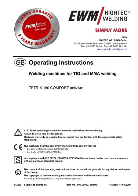
<strong>EWM</strong><br />
HIGHTEC WELDING <strong>GmbH</strong><br />
Dr. Günter-Henle-Straße 8 • D-56271 Mündersbach<br />
Fon +49 2680 181-0 • Fax +49 2680 181-244<br />
www.ewm.de • info@ewm.de<br />
GB<br />
<strong>Operating</strong> <strong>instructions</strong><br />
<strong>Welding</strong> machines for TIG and MMA welding<br />
TETRIX 180 COMFORT activArc<br />
N. B. These operating <strong>instructions</strong> must be read before commissioning.<br />
Failure to do so may be dangerous.<br />
Machines may only be operated by personnel who are familiar with the appropriate safety<br />
regulations.<br />
The machines bear the conformity mark and thus comply with the<br />
• EC Low Voltage Directive (2006/95/ EG)<br />
• EC EMC Directive (2004/108/ EG)<br />
In compliance with IEC 60974, EN 60974, VDE 0544 the machines can be used in environments<br />
with an increased electrical hazard.<br />
©<br />
The content of the operating <strong>instructions</strong> does not constitute grounds for any claims on the part<br />
of the buyer.<br />
The copyright to these operating <strong>instructions</strong> remains with the manufacturer.<br />
Reprinting, including extracts, only with written approval.<br />
© 2009 Subject to alteration. Item No.: 099-000097-<strong>EWM</strong>01 Revised: 14.09.2009
Mündersbach, 25 February 2009<br />
Dear customer,<br />
Thank you for your order.<br />
Premium quality – made in Germany and with a three-year warranty.<br />
The machines from <strong>EWM</strong> are impressive, with innovative technology, exceptional user-friendliness and<br />
the most up to date inverter and control systems. This makes welding possible that is simple, efficient<br />
and resource-saving as well as being highly economical!<br />
Perfection doesn't happen by coincidence: Every single component is 100% tested and the machine is<br />
“free welded” before it is delivered.<br />
Our comprehensive service offer and the highly developed modern <strong>EWM</strong> quality management system<br />
guarantee worldwide premium quality “Made in Germany” and a three-year warranty.<br />
Continual further development and optimisation has made us Germany’s market leader in the<br />
manufacture of light arc welding machines. We have manufacturing, training and service locations<br />
throughout the world to advise you and provide you with a comprehensive range of services.<br />
The accompanying operating <strong>instructions</strong> contain everything about commissioning the machine, notes<br />
regarding safety, maintenance and care, technical data as well as information regarding the warranty. It<br />
is very important to observe all our <strong>instructions</strong> in order to achieve optimal welding results with the<br />
machine and to ensure many years of safe operation.<br />
Thank you for the trust that you have placed in us. We look forward to a long-term and, above all,<br />
successful partnership with you.<br />
Yours faithfully<br />
<strong>EWM</strong> HIGHTEC WELDING <strong>GmbH</strong><br />
Bernd Szczesny<br />
Executive management
Machine and Company Data<br />
Please enter the <strong>EWM</strong> machine data and your company’s data in the appropriate fields.<br />
TYP:<br />
<strong>EWM</strong> HIGHTEC WELDING GMBH<br />
D-56271 MÜNDERSBACH<br />
SNR:<br />
ART:<br />
GEPRÜFT/CONTROL:<br />
PROJ:<br />
CE<br />
Name of Customer / company<br />
Name of Customer / company<br />
Adress<br />
Adress<br />
Post code / Place<br />
Post code / Place<br />
Country<br />
Country<br />
Stamp / Signature of <strong>EWM</strong>-distibutor<br />
Date of purchase<br />
Stamp / Signature of <strong>EWM</strong>-distibutor<br />
Date of purchase<br />
3
Contents<br />
Notes on the use of these operating <strong>instructions</strong><br />
1 Contents<br />
1 Contents ..................................................................................................................................................4<br />
2 Safety <strong>instructions</strong> .................................................................................................................................8<br />
2.1 Notes on the use of these operating <strong>instructions</strong>...........................................................................8<br />
2.2 General.........................................................................................................................................10<br />
2.3 Transport and installation.............................................................................................................13<br />
2.4 Ambient conditions.......................................................................................................................14<br />
2.4.1 In operation...................................................................................................................14<br />
2.4.2 Transport and storage ..................................................................................................14<br />
3 Technical data.......................................................................................................................................15<br />
3.1 TETRIX 180 COMFORT ..............................................................................................................15<br />
4 Machine description.............................................................................................................................16<br />
4.1 TETRIX 180 COMFORT ..............................................................................................................16<br />
4.1.1 Front view .....................................................................................................................16<br />
4.1.2 Rear view......................................................................................................................17<br />
4.2 Machine control – <strong>Operating</strong> elements ........................................................................................18<br />
4.2.1.1 Function sequence........................................................................................20<br />
5 Functional characteristics...................................................................................................................22<br />
5.1 TIG welding ..................................................................................................................................22<br />
5.2 <strong>Operating</strong> concepts ......................................................................................................................22<br />
5.2.1 Manual, standard operation (JOB 0) ............................................................................22<br />
5.2.2 Save welding tasks (JOBs)...........................................................................................23<br />
5.2.2.1 Displaying and changing the JOB number....................................................23<br />
5.2.3 <strong>Welding</strong> data display.....................................................................................................23<br />
5.2.3.1 <strong>Welding</strong> parameter setting ............................................................................23<br />
5.2.4 Arc ignition ....................................................................................................................24<br />
5.2.4.1 HF ignition .....................................................................................................24<br />
5.2.4.2 Liftarc ignition ................................................................................................24<br />
5.2.5 TIG automatic cut-out ...................................................................................................24<br />
5.2.6 Function sequences/operating modes..........................................................................25<br />
5.2.6.1 Explanation of symbols .................................................................................25<br />
5.2.6.2 Non-latched mode.........................................................................................26<br />
5.2.6.3 Latched mode................................................................................................27<br />
5.2.6.4 TIG spotArc ...................................................................................................28<br />
5.2.6.5 Non-latched operation, version C..................................................................30<br />
5.2.7 Pulses, function sequences..........................................................................................31<br />
5.2.7.1 Non-latched mode.........................................................................................31<br />
5.2.7.2 Latched mode................................................................................................31<br />
5.2.8 Pulse variants ...............................................................................................................32<br />
5.2.8.1 Pulses (thermal pulses).................................................................................32<br />
5.2.8.2 KHz pulses (metallurgic pulses)....................................................................33<br />
5.2.8.3 Automated pulses..........................................................................................33<br />
5.2.9 TIG activArc welding.....................................................................................................34<br />
5.2.10 Shielding gas setting.....................................................................................................35<br />
5.2.10.1 Gas test .......................................................................................................35<br />
5.2.11 <strong>Welding</strong> torch (operating variants)................................................................................35<br />
5.2.11.1 Tap torch trigger (tapping function).............................................................35<br />
5.2.12 Torch mode and up/down speed setting ......................................................................36<br />
5.2.12.1 Standard TIG torch (5-pole) ........................................................................37<br />
5.2.12.2 TIG up/down torch (8-pole) .........................................................................39<br />
5.2.12.3 Potentiometer torch (8-pole) .......................................................................41<br />
5.2.12.4 RETOX TIG torch (12-pole) ........................................................................42<br />
5.2.13 Setting the first increment.............................................................................................43<br />
4 Item No.: 099-000097-<strong>EWM</strong>01
Contents<br />
Notes on the use of these operating <strong>instructions</strong><br />
5.3 MMA welding ...............................................................................................................................44<br />
5.3.1 Selection and adjustment .............................................................................................44<br />
5.3.2 Hotstart .........................................................................................................................44<br />
5.3.2.1 Hotstart current .............................................................................................44<br />
5.3.2.2 Hotstart time..................................................................................................44<br />
5.3.3 Arcforce ........................................................................................................................45<br />
5.3.4 Antistick ........................................................................................................................45<br />
5.4 Remote control.............................................................................................................................46<br />
5.4.1 Manual remote control RT 1.........................................................................................46<br />
5.4.2 Manual remote control RTP 1 ......................................................................................46<br />
5.4.3 Manual remote control RTP 2 ......................................................................................46<br />
5.4.4 RTP 3 manual remote control ......................................................................................46<br />
5.4.5 Foot-operated remote control RTF 1............................................................................47<br />
5.5 Advanced settings........................................................................................................................48<br />
5.5.1 Setting slope times for secondary current AMP% or pulse edges ...............................48<br />
5.5.2 TIG non-latched operating mode, C version ................................................................49<br />
5.5.3 Configuring the TIG potentiometer torch connection ...................................................50<br />
5.5.4 <strong>Welding</strong> current display (ignition, secondary, end and hotstart currents) ....................51<br />
5.5.5 Ramp function foot-operated remote control RTF 1.....................................................52<br />
5.6 Interfaces for automation .............................................................................................................53<br />
5.6.1 Remote control connection socket, 19-pole .................................................................53<br />
5.7 Menus and sub-menus on the machine control...........................................................................54<br />
5.7.1 Direct menus (direct access to parameters) ................................................................54<br />
5.7.2 Expert menu (TIG)........................................................................................................54<br />
5.7.3 Machine configuration menu ........................................................................................55<br />
6 Commissioning ....................................................................................................................................58<br />
6.1 General ........................................................................................................................................58<br />
6.2 Installation....................................................................................................................................58<br />
6.3 Machine cooling...........................................................................................................................58<br />
6.4 Area of application – proper usage..............................................................................................59<br />
6.5 Workpiece lead, general ..............................................................................................................59<br />
6.6 Mains connection.........................................................................................................................60<br />
6.6.1 Mains configuration ......................................................................................................60<br />
6.7 TIG welding..................................................................................................................................61<br />
6.7.1 <strong>Welding</strong> torch connection .............................................................................................61<br />
6.7.2 Connection for workpiece lead .....................................................................................62<br />
6.7.3 Torch connection options and pin assignments ...........................................................62<br />
6.7.4 Shielding gas supply (shielding gas cylinder for welding machine) .............................62<br />
6.7.4.1 Connecting the shielding gas supply ............................................................63<br />
6.7.4.2 Setting the shielding gas quantity .................................................................63<br />
6.8 MMA welding ...............................................................................................................................64<br />
6.8.1 Connecting the electrode holder and workpiece lead ..................................................64<br />
Item No.: 099-000097-<strong>EWM</strong>01 5
Contents<br />
Notes on the use of these operating <strong>instructions</strong><br />
7 Maintenance and testing .....................................................................................................................66<br />
7.1 General.........................................................................................................................................66<br />
7.2 Cleaning .......................................................................................................................................66<br />
7.3 Test ..............................................................................................................................................67<br />
7.3.1 Test equipment .............................................................................................................67<br />
7.3.2 Scope of the test...........................................................................................................68<br />
7.3.3 Visual inspection...........................................................................................................68<br />
7.3.4 Measuring the open circuit voltage...............................................................................68<br />
7.3.5 Measurement of insulation resistance ..........................................................................68<br />
7.3.6 Measuring the leakage current (protective conductor and contact current) .................69<br />
7.3.7 Measurement of protective conductor resistance.........................................................69<br />
7.3.8 Functional test of the welding machine ........................................................................69<br />
7.3.9 Documentation of the test.............................................................................................69<br />
7.4 Repair Work .................................................................................................................................70<br />
7.5 Disposing of equipment................................................................................................................71<br />
7.5.1 Manufacturer's declaration to the end user ..................................................................71<br />
7.6 Meeting the requirements of RoHS..............................................................................................71<br />
8 Warranty ................................................................................................................................................72<br />
8.1 General Validity............................................................................................................................72<br />
8.2 Warranty Declaration ...................................................................................................................73<br />
9 <strong>Operating</strong> problems, causes and remedies.......................................................................................74<br />
9.1 Error messages (power source)...................................................................................................74<br />
9.2 Resetting welding parameters to the factory settings ..................................................................75<br />
9.3 Display machine control software version....................................................................................76<br />
9.4 General operating problems ........................................................................................................77<br />
9.4.1 Interface for mechanised welding.................................................................................77<br />
10 Accessories, options ...........................................................................................................................78<br />
10.1 TIG welding torch .........................................................................................................................78<br />
10.2 Electrode holder / workpiece lead................................................................................................78<br />
10.3 Remote controls and accessories................................................................................................78<br />
10.4 Options.........................................................................................................................................78<br />
10.5 General accessories ....................................................................................................................78<br />
11 Circuit diagrams ...................................................................................................................................79<br />
11.1 TETRIX 180 COMFORT ..............................................................................................................79<br />
12 Appendix A............................................................................................................................................81<br />
12.1 Declaration of Conformity.............................................................................................................81<br />
6 Item No.: 099-000097-<strong>EWM</strong>01
Contents<br />
Notes on the use of these operating <strong>instructions</strong><br />
Item No.: 099-000097-<strong>EWM</strong>01 7
Safety <strong>instructions</strong><br />
Notes on the use of these operating <strong>instructions</strong><br />
2 Safety <strong>instructions</strong><br />
2.1 Notes on the use of these operating <strong>instructions</strong><br />
DANGER<br />
Working or operating procedures which must be closely observed to prevent imminent<br />
serious and even fatal injuries.<br />
• Safety notes include the "DANGER" keyword in the heading with a general warning symbol.<br />
• The hazard is also highlighted using a symbol on the edge of the page.<br />
WARNING<br />
Working or operating procedures which must be closely observed to prevent serious<br />
and even fatal injuries.<br />
• Safety notes include the "WARNING" keyword in the heading with a general warning<br />
symbol.<br />
• The hazard is also highlighted using a symbol in the page margin.<br />
CAUTION<br />
Working or operating procedures which must be closely observed to prevent possible<br />
minor personal injury.<br />
• The safety information includes the "CAUTION" keyword in its heading with a general<br />
warning symbol.<br />
• The risk is explained using a symbol on the edge of the page.<br />
CAUTION<br />
Working and operating procedures which must be followed precisely to avoid damaging<br />
or destroying the product.<br />
• The safety information includes the "CAUTION" keyword in its heading without a general<br />
warning symbol.<br />
• The hazard is explained using a symbol at the edge of the page.<br />
NOTE<br />
Special technical points which users must observe.<br />
• Notes include the "NOTE" keyword in the heading without a general warning symbol.<br />
• Notes are highlighted using a "hand" symbol at the edge of the page.<br />
8 Item No.: 099-000097-<strong>EWM</strong>01
Safety <strong>instructions</strong><br />
Notes on the use of these operating <strong>instructions</strong><br />
Instructions and lists detailing step-by-step actions for given situations can be recognised via bullet<br />
points, e.g.:<br />
• Insert the welding current lead socket into the relevant socket and lock.<br />
Symbol<br />
Description<br />
Press<br />
Do not press<br />
Turn<br />
Switch<br />
0<br />
1 Switch off machine<br />
0<br />
1 Switch on machine<br />
ENTER (enter the menu)<br />
NAVIGATION (Navigating in the menu)<br />
EXIT (Exit the menu)<br />
Time display (example: wait 4s/press)<br />
Interruption in the menu display (other setting options possible)<br />
Tool not required/do not use<br />
Tool required/use<br />
Item No.: 099-000097-<strong>EWM</strong>01 9
Safety <strong>instructions</strong><br />
General<br />
2.2 General<br />
DANGER<br />
Electromagnetic fields!<br />
The power source may cause electrical or electromagnetic fields to be produced which<br />
could affect the correct functioning of electronic equipment such as IT or CNC devices,<br />
telecommunication lines, power cables, signal lines and pacemakers.<br />
• Observe the maintenance <strong>instructions</strong>! (see Maintenance and Testing chapter)<br />
• Unwind welding lines completely!<br />
• Shield devices or equipment sensitive to radiation accordingly!<br />
• The correct functioning of pacemakers may be affected (obtain advice from a doctor if<br />
necessary).<br />
Do not carry out any unauthorised repairs or modifications!<br />
To avoid injury and equipment damage, the unit must only be repaired or modified by<br />
specialist, skilled persons!<br />
The warranty becomes null and void in the event of unauthorised interference.<br />
• Appoint only skilled persons for repair work (trained service personnel)!<br />
Electric shock!<br />
<strong>Welding</strong> machines use high voltages which can result in potentially fatal electric shocks<br />
and burns on contact. Even low voltages can cause you to get a shock and lead to<br />
accidents.<br />
• Do not touch any live parts in or on the machine!<br />
• Connection cables and leads must be free of faults!<br />
• Switching off alone is not sufficient! Wait for 2 minutes until the capacitors have discharged.<br />
• Place welding torch and stick electrode holder on an insulated surface!<br />
• The unit should only be opened by specialist staff after the mains plug has been unplugged!<br />
• Only wear dry protective clothing!<br />
WARNING<br />
Risk of injury due to radiation or heat!<br />
Arc radiation results in injury to skin and eyes.<br />
Contact with hot workpieces and sparks results in burns.<br />
• Wear dry protective clothing (e.g. welding shield, gloves, etc.) according to the relevant<br />
regulations in the country in question!<br />
• Protect persons not involved in the work against arc beams and the risk of glare using safety<br />
curtains!<br />
Explosion risk!<br />
Apparently harmless substances in closed containers may generate excessive pressure<br />
when heated.<br />
• Move containers with inflammable or explosive liquids away from the working area!<br />
• Never heat explosive liquids, dusts or gases by welding or cutting!<br />
10 Item No.: 099-000097-<strong>EWM</strong>01
Safety <strong>instructions</strong><br />
General<br />
WARNING<br />
Smoke and gases!<br />
Smoke and gases can lead to breathing difficulties and poisoning. In addition, solvent<br />
vapour (chlorinated hydrocarbon) may be converted into poisonous phosgene due to the<br />
ultraviolet radiation of the arc!<br />
• Ensure that there is sufficient fresh air!<br />
• Keep solvent vapour away from the arc beam field!<br />
• Wear suitable breathing apparatus if appropriate!<br />
Fire hazard!<br />
Flames may arise as a result of the high temperatures, stray sparks, glowing-hot parts<br />
and hot slag produced during the welding process.<br />
Stray welding currents can also result in flames forming!<br />
• Check for fire hazards in the working area!<br />
• Do not carry any easily flammable objects such as matches or lighters.<br />
• Keep appropriate fire extinguishing equipment to hand in the working area!<br />
• Thoroughly remove any residue of flammable substances from the workpiece before starting<br />
welding.<br />
• Only continue work on welded workpieces once they have cooled down.<br />
Do not allow to come into contact with flammable material!<br />
• Connect welding leads correctly!<br />
Risk of accidents if these safety <strong>instructions</strong> are not observed!<br />
Non-observance of these safety <strong>instructions</strong> is potentially fatal!<br />
• Carefully read the safety information in this manual!<br />
• Observe the accident prevention regulations in your country.<br />
• Inform persons in the working area that they must observe the regulations!<br />
CAUTION<br />
Noise exposure!<br />
Noise exceeding 70 dBA can cause permanent hearing damage!<br />
• Wear suitable ear protection!<br />
• Persons located within the working area must wear suitable ear protection!<br />
Item No.: 099-000097-<strong>EWM</strong>01 11
Safety <strong>instructions</strong><br />
General<br />
CAUTION<br />
Obligations of the operator!<br />
In the European Economic Area (EEA), the relevant national version of the basic<br />
guidelines must be followed and observed!<br />
• National version of the basic guidelines (89/391/EEC) as well as the relevant individual<br />
guidelines.<br />
• In particular the Directive (89/655/EEC) on the minimum regulations for safety and health<br />
protection when staff members are using equipment during work.<br />
• The accident prevention regulations of the relevant country (e.g. in Germany, BGV D 1).<br />
• Check at regular intervals that users are working in a safety-conscious way!<br />
Damage due to the use of non-genuine parts!<br />
The manufacturer's warranty becomes void if non-genuine parts are used!<br />
• Only use system components and options (power sources, welding torches, electrode<br />
holders, remote controls, spare parts and replacement parts, etc.) from our range of<br />
products!<br />
• Only insert and lock accessory components into the relevant connection socket when the<br />
machine is switched off.<br />
Electromagnetic interference!<br />
The machines are intended to be used in industrial areas, according to IEC 60974-10. If<br />
they are used in residential areas, for example, problems may occur with ensuring<br />
electromagnetic compatibility.<br />
• Check whether interference is caused to other machines!<br />
12 Item No.: 099-000097-<strong>EWM</strong>01
Safety <strong>instructions</strong><br />
Transport and installation<br />
2.3 Transport and installation<br />
WARNING<br />
Incorrect handling of shielding gas cylinders!<br />
Incorrect handling of shielding gas cylinders can result in serious and even fatal injury.<br />
• Observe the <strong>instructions</strong> from the gas manufacturer and in any relevant regulations<br />
concerning the use of compressed air!<br />
• Place shielding gas cylinders in the holders provided for them and secure with fixing<br />
devices.<br />
• Avoid heating the shielding gas cylinder!<br />
CAUTION<br />
Risk of tipping!<br />
There is a risk of the machine tipping over and injuring persons or being damaged itself<br />
during movement and set up. Tilt resistance is guaranteed up to an angle of 10°<br />
(according to IEC 60974-1, -3, -10).<br />
• Set up and transport the machine on level, solid ground.<br />
• Secure add-on parts using suitable equipment.<br />
Damage due to supply lines not being disconnected!<br />
During transport, supply lines which have not been disconnected (mains supply leads,<br />
control leads, etc.) may cause hazards such as connected equipment tipping over and<br />
injuring persons!<br />
• Disconnect supply lines!<br />
CAUTION<br />
Equipment damage when not operated in an upright position!<br />
The units are designed for operation in an upright position!<br />
Operation in non-permissible positions can cause equipment damage.<br />
• Only transport and operate in an upright position!<br />
Item No.: 099-000097-<strong>EWM</strong>01 13
Safety <strong>instructions</strong><br />
Ambient conditions<br />
2.4 Ambient conditions<br />
CAUTION<br />
Equipment damage due to dirt accumulation!<br />
Unusually high quantities of dust, acid, corrosive gases or substances may damage the<br />
equipment.<br />
• Avoid high volumes of smoke, vapour, oil vapour and grinding dust!<br />
• Avoid ambient air containing salt (sea air)!<br />
Non-permissible ambient conditions!<br />
Insufficient ventilation results in a reduction in performance and equipment damage.<br />
• Observe the ambient conditions!<br />
• Keep the cooling air inlet and outlet clear!<br />
• Observe the minimum distance of 0.5 m from obstacles!<br />
Installation site!<br />
The machine must not be operated in the open air and must only be set up and operated<br />
on a suitable, stable and level base!<br />
• The operator must ensure that the ground is non-slip and level, and provide sufficient<br />
lighting for the place of work.<br />
• Safe operation of the machine must be guaranteed at all times.<br />
2.4.1 In operation<br />
Temperature range of the ambient air:<br />
• -20 °C to +40 °C<br />
Relative air humidity:<br />
• Up to 50% at 40 °C<br />
• Up to 90% at 20 °C<br />
2.4.2 Transport and storage<br />
Storage in an enclosed space, temperature range of the ambient air:<br />
• -25 °C to +55 °C<br />
Relative air humidity<br />
• Up to 90% at 20 °C<br />
14 Item No.: 099-000097-<strong>EWM</strong>01
3 Technical data<br />
3.1 TETRIX 180 COMFORT<br />
TIG<br />
Technical data<br />
TETRIX 180 COMFORT<br />
MMA<br />
<strong>Welding</strong> current setting range 5A-180 A 10A-150 A<br />
<strong>Welding</strong> voltage setting range 10.2 V-17.2 V 20.2 V-26.0 V<br />
Duty cycle at 25 °C<br />
35% DC 180 A -<br />
50% DC - 150 A<br />
60% DC 150 A -<br />
100% DC 120 A 120 A<br />
Duty cycle at 40 °C<br />
35% DC 180 A 150 A<br />
60% DC 150 A 120 A<br />
100% DC 120 A 100 A<br />
Load alternation<br />
Open circuit voltage<br />
10 min. (60% DC ∧ 6 min. welding, 4 min. pause)<br />
90 V<br />
Mains voltage (tolerances) 1 x 230 V (-40% to +15%)<br />
Frequency<br />
Mains fuse (safety fuse, slow-blow)<br />
Mains connection lead<br />
50/60 Hz<br />
1 x 16 A<br />
H07RN-F3G2.5<br />
Max. connected power 4.4.1 kVA 5.5.1 kVA<br />
Recommended generator rating<br />
7.5.1 kVA<br />
cos ϕ 0.94<br />
Insulation class/protection classification H/IP 23<br />
Ambient temperature -20 °C to +40 °C<br />
Machine cooling<br />
Workpiece lead 35 mm 2<br />
Dimensions L/W/H<br />
Weight<br />
Fan<br />
430 x 180 x 295 mm<br />
8.9 kg<br />
Constructed to standards IEC 60974-1, -3, -10<br />
/<br />
Item No.: 099-000097-<strong>EWM</strong>01 15
Machine description<br />
TETRIX 180 COMFORT<br />
4 Machine description<br />
NOTE<br />
The maximum possible machine configuration is given in the text description.<br />
If necessary, the optional connection may need to be retrofitted (see "Accessories"<br />
chapter).<br />
4.1 TETRIX 180 COMFORT<br />
4.1.1 Front view<br />
1<br />
2<br />
3<br />
4<br />
5<br />
6<br />
7<br />
Figure 4-1<br />
Item Symbol Description 0<br />
1 Carrying strap<br />
2 Machine control<br />
See Machine control – operating elements chapter<br />
3 Connection socket, “+” welding current<br />
Connection for workpiece lead<br />
4 Connection socket, 5-pole/8-pole/12-pole<br />
5-pole: Standard TIG torch control lead<br />
8-pole: TIG Up/Down or potentiometer torch control lead<br />
12-pole: Control lead for TIG up/down torch with display (option)<br />
5 G¼” connecting nipple, “-” welding current<br />
Shielding gas connection (with yellow insulating cap) for TIG welding torch<br />
6 Connection socket, “-” welding current<br />
TIG welding torch connection<br />
7 Cooling air inlet<br />
16 Item No.: 099-000097-<strong>EWM</strong>01
Machine description<br />
TETRIX 180 COMFORT<br />
4.1.2 Rear view<br />
1<br />
6<br />
2<br />
3<br />
4<br />
5<br />
7<br />
Item Symbol Description 0<br />
1 Main switch, machine on/off<br />
Figure 4-2<br />
2<br />
3<br />
HF<br />
HF<br />
Ignition type changeover switch<br />
HF =<br />
HF =<br />
Liftarc (contact ignition)<br />
HF ignition<br />
PC interface, serial (D-SUB connection socket, 9-pole)<br />
COM<br />
4 G¼” connecting nipple<br />
Shielding gas connection on the pressure reducer<br />
5 Connection socket, 19-pole<br />
Remote control connection<br />
6 Mains connection cable<br />
7 Cooling air inlet<br />
Item No.: 099-000097-<strong>EWM</strong>01 17
Machine description<br />
Machine control – <strong>Operating</strong> elements<br />
4.2 Machine control – <strong>Operating</strong> elements<br />
NOTE<br />
Machine control provides the user with up to 8 welding tasks (JOBs).<br />
JOB 0 represents manual operating mode. This is where you can change/optimise all<br />
parameters directly in machine control (see chapter "<strong>Operating</strong> concepts").<br />
COMFORT<br />
S<br />
6<br />
AMP<br />
VOLT<br />
JOB<br />
S<br />
7<br />
AMP%<br />
sec<br />
8<br />
sec<br />
AMP<br />
5<br />
sec<br />
AMP%<br />
4<br />
sec<br />
1<br />
AMP%<br />
Puls<br />
2<br />
Automatic<br />
sec<br />
kHz<br />
3<br />
sec<br />
AMP<br />
JOB<br />
kHz<br />
%<br />
sec<br />
Figure 4-3<br />
Item Symbol Description 0<br />
1 <strong>Welding</strong> process button<br />
MMA welding, lights up in green / arcforce setting, lights up in red<br />
TIG welding<br />
2<br />
<strong>Operating</strong> mode button<br />
spotArc (spot time setting range 0.01 sec. to 20.0 sec.)<br />
3<br />
4<br />
Puls<br />
Automatic<br />
sec<br />
kHz<br />
Non-latched<br />
Latched<br />
TIG pulses key button<br />
TIG automated pulses (frequency and balance)<br />
sec<br />
kHz<br />
TIG pulses with times, lights up in green / Fast TIG DC pulses with<br />
frequency and balance, lights up in red<br />
Display changeover button<br />
<strong>Welding</strong> current display<br />
<strong>Welding</strong> voltage display<br />
JOB number display<br />
18 Item No.: 099-000097-<strong>EWM</strong>01
Machine description<br />
Machine control – <strong>Operating</strong> elements<br />
Item Symbol Description 0<br />
5 <strong>Welding</strong> parameter setting rotary dial<br />
Setting all parameters such as ignition, welding, end current, gas pre-flow and gas<br />
post-flow times, pulse edges, etc.<br />
6 Three-figure LED display<br />
<strong>Welding</strong> parameter display (see also chap. “<strong>Welding</strong> data display”).<br />
7<br />
Error/status indicators<br />
Collective interference signal light (see <strong>Operating</strong> problems chapter)<br />
S<br />
S<br />
Water deficiency signal light (welding torch cooling)<br />
Excess temperature signal light<br />
safety sign signal light<br />
8 Function sequence (see next chapter)<br />
Item No.: 099-000097-<strong>EWM</strong>01 19
Machine description<br />
Machine control – <strong>Operating</strong> elements<br />
4.2.1.1 Function sequence<br />
Figure 4-4<br />
Item Symbol Description 0<br />
1 Select welding parameters button<br />
This button is used to select the welding parameters depending on the welding process<br />
and operating mode used.<br />
2<br />
sec<br />
Gas pre-flow time (TIG), absolute setting range 0.0 sec to 20.0 sec (0.1s increments).<br />
3<br />
Ignition current (TIG)<br />
AMP%<br />
Percentage of the main current.<br />
Setting range 1 % to 200 %<br />
(1 % increments). There are no pulses<br />
during the ignition current phase.<br />
4 sec Up-slope time (TIG)<br />
Setting ranges: 0.00 s to 20.0 s<br />
(0.1 s increments).<br />
The up-slope time can be set separately<br />
for non-latched and latched.<br />
5<br />
6<br />
7<br />
8<br />
sec<br />
AMP<br />
sec<br />
AMP%<br />
Hotstart current (MMA)<br />
Percentage of the main current. Setting<br />
range 1 % to 200 %<br />
(1 % increments).<br />
Hotstart time (MMA)<br />
Setting ranges: 0.00 s to 20.0 s<br />
(0.1 s increments).<br />
Pulse time / slope time from AMP% to AMP / Spot time<br />
• Pulse time setting range: 0.01 s to 20.0 s<br />
(0.01 s increments < 0.5 s; 0.1 s increments > 0.5 s)<br />
Die Pulszeit gilt für die Hauptstromphase (AMP) beim Pulsen.<br />
• Slope time (tS2) setting range: 0.0 s to 20.0 s<br />
(see chapter "Advanced settings")<br />
Main current (TIG) / pulse current<br />
I min to I max (1 A increments)<br />
Main current (MMA)<br />
I min to I max (1 A increments)<br />
Pulse pause time / slope time from AMP to AMP%<br />
• Pulse pause setting range: 0.01 sec to 20.0 sec<br />
(0.01 sec increments < 0.5 sec; 0.1 sec increments > 0.5 sec)<br />
• Slope time (tS1) setting range: 0.0 sec to 20.0 sec<br />
(see chapter "Advanced settings")<br />
The pulse time applies to the secondary current phase (AMP%)<br />
Secondary current (TIG) / pulse pause current<br />
Setting range 1 % to 100 % (1 % increments). Percentage of the main current.<br />
20 Item No.: 099-000097-<strong>EWM</strong>01
Machine description<br />
Machine control – <strong>Operating</strong> elements<br />
Item Symbol Description 0<br />
9<br />
10<br />
11<br />
sec<br />
AMP%<br />
sec<br />
Down-slope time (TIG)<br />
0.00 sec to 20.0 sec (0.1 sec increments).<br />
The down-slope time can be set separately for non-latched and latched.<br />
End-crater current (TIG)<br />
Setting range 1 % to 200 % (1 % increments). Percentage of the main current.<br />
Gas post-flow time (TIG)<br />
Setting ranges: 0.00 sec to 40.0 sec (0.1 sec increments).<br />
12 Balance TIG DC pulses (15 kHz)<br />
Setting range: 1% to +99% (1% increments).<br />
13 Frequency TIG DC pulses (15 kHz)<br />
Setting range: 50 Hz to 15 kHz<br />
14 activArc TIG welding process<br />
• Switch activArc on or off<br />
• Correct the activArc characteristic (setting range: 0 to 100)<br />
Item No.: 099-000097-<strong>EWM</strong>01 21
Functional characteristics<br />
TIG welding<br />
5 Functional characteristics<br />
5.1 TIG welding<br />
NOTE<br />
Machine control provides the user with up to 8 welding tasks (JOBs).<br />
JOB 0 represents manual operating mode. This is where you can change/optimise all<br />
parameters directly in machine control (see chapter "<strong>Operating</strong> concepts").<br />
5.2 <strong>Operating</strong> concepts<br />
5.2.1 Manual, standard operation (JOB 0)<br />
NOTE<br />
It is only possible to change the basic welding parameters if:<br />
• No welding current is flowing and<br />
• The key switch (option) is set to position “1”.<br />
"Manual, standard operation (JOB 0)" is set by default on delivery and every time the machine control is<br />
reset. This means that the welder repeatedly makes all the required welding settings and re-adjusts them<br />
for each individual welding task.<br />
<strong>Operating</strong><br />
element<br />
Action<br />
Result<br />
Select and display welding process<br />
TIG welding<br />
+<br />
TIG activArc welding<br />
Puls<br />
Automatic<br />
sec<br />
kHz<br />
MMA welding, lights up in green/arcforce setting, lights up in<br />
red<br />
Select and display operating mode<br />
spotArc (spot time setting range 0.01 sec. to 20.0 sec.)<br />
Non-latched<br />
Latched<br />
Select and display pulse procedure<br />
TIG automated pulses (frequency and balance)<br />
sec<br />
kHz<br />
TIG pulses with times, lights up in green/fast TIG DC pulses<br />
with frequency and balance, lights up in red<br />
Select welding parameter in the functional sequence<br />
Set welding parameters<br />
22 Item No.: 099-000097-<strong>EWM</strong>01
Functional characteristics<br />
<strong>Operating</strong> concepts<br />
5.2.2 Save welding tasks (JOBs)<br />
You can select, change and save the required welding parameters for recurring welding tasks (JOBs) in<br />
up to 7 JOBs (JOB 1 to JOB 7).<br />
5.2.2.1 Displaying and changing the JOB number<br />
<strong>Operating</strong> Action Result<br />
element<br />
Select JOB display<br />
n x<br />
Change the JOB number<br />
1 x<br />
If the display switchover is pressed or if there is no keyboard input for 5<br />
seconds, the new JOB will be active<br />
NOTE<br />
The procedure for setting welding tasks is the same as described under "Manual,<br />
standard operation (JOB 0)". A JOB can only be switched if no welding current is<br />
flowing.<br />
The up-slope and down-slope times can be set separately for non-latched and latched.<br />
5.2.3 <strong>Welding</strong> data display<br />
The following welding parameters can be displayed before (nominal values) or during (actual values)<br />
welding.<br />
Parameter<br />
Before welding<br />
(nominal values)<br />
During welding<br />
(actual values)<br />
<strong>Welding</strong> current <br />
<strong>Welding</strong> voltage <br />
JOB number <br />
Parameter times <br />
Parameter currents <br />
5.2.3.1 <strong>Welding</strong> parameter setting<br />
The parameters that can be set in the function sequence of the machine control depend on the selected<br />
welding task. This means that if for example you have not selected a pulse variant, then you cannot set<br />
any pulse times in the function sequence.<br />
Item No.: 099-000097-<strong>EWM</strong>01 23
Functional characteristics<br />
<strong>Operating</strong> concepts<br />
5.2.4 Arc ignition<br />
5.2.4.1 HF ignition<br />
Figure 5-1<br />
The arc is started without contact from high-voltage ignition pulses.<br />
a) Position the welding torch in welding position over the workpiece (distance between the electrode tip<br />
and workpiece should be approx. 2-3mm).<br />
b) Press the torch trigger (high voltage ignition pulses ignite the arc).<br />
c) Ignition current flows, and the welding process is continued depending on the operating mode<br />
selected.<br />
End the welding process: Release or press the torch trigger depending on the operating mode<br />
selected.<br />
5.2.4.2 Liftarc ignition<br />
a) b) c)<br />
Figure 5-2<br />
The arc is ignited on contact with the workpiece:<br />
a) Carefully place the torch gas nozzle and tungsten electrode tip onto the workpiece and press the torch<br />
trigger (liftarc current flowing, regardless of the main current set).<br />
b) Incline the torch over the torch gas nozzle to produce a gap of approx. 2-3 mm between the electrode<br />
tip and the workpiece. The arc ignites and the welding current is increased, depending on the<br />
operating mode set, to the ignition or main current set.<br />
c) Lift off the torch and swivel to the normal position.<br />
Ending the welding process: Release or press the torch trigger depending on the operating mode<br />
selected.<br />
5.2.5 TIG automatic cut-out<br />
NOTE<br />
The automatic cut-out function will be triggered by two conditions during the welding<br />
process:<br />
During the ignition phase (ignition fault)<br />
• If there is no welding current within 3s after starting the welding.<br />
During the welding phase (arc interruption)<br />
• If the arc is interrupted for longer than 3s.<br />
In both cases, the welding machine ends the ignition or welding process immediately.<br />
24 Item No.: 099-000097-<strong>EWM</strong>01
Functional characteristics<br />
<strong>Operating</strong> concepts<br />
5.2.6 Function sequences/operating modes<br />
The "Select welding parameter" button and the "<strong>Welding</strong> parameter setting" rotary transducer can be<br />
used to control all the parameters for the TIG process:<br />
Item Symbol Description 0<br />
Figure 5-3<br />
1 Select welding parameters button<br />
This button is used to select the welding parameters depending on the welding process<br />
and operating mode used.<br />
2 <strong>Welding</strong> parameter setting rotary dial<br />
Setting all parameters such as ignition, welding, end current, gas pre-flow and gas<br />
post-flow times, pulse edges, etc.<br />
5.2.6.1 Explanation of symbols<br />
Symbol Meaning<br />
Press torch trigger 1<br />
Release torch trigger 1<br />
I<br />
t<br />
Current<br />
Time<br />
Gas pre-flows<br />
I start<br />
t Up<br />
tP<br />
AMP<br />
AMP%<br />
t1<br />
t2<br />
ts1<br />
ts2<br />
t Down<br />
I end<br />
Ignition current<br />
Up-slope time<br />
Spot time<br />
Main current (minimum to maximum current)<br />
Secondary current (0% to 100% of AMP)<br />
Pulse time<br />
Pulse pause time<br />
TIG pulses: Slop time from main current (AMP) to secondary current (AMP%)<br />
TIG pulses: Slop time from secondary current (AMP%) to main current (AMP)<br />
Down-slope time<br />
End-crater current<br />
Gas post-flows<br />
Item No.: 099-000097-<strong>EWM</strong>01 25
Functional characteristics<br />
<strong>Operating</strong> concepts<br />
5.2.6.2 Non-latched mode<br />
NOTE<br />
When the foot-operated remote control RTF is connected, the machine switches<br />
automatically to non-latched operation.<br />
The up- and down-slopes are switched off.<br />
Figure 5-4<br />
1st cycle:<br />
• Press and hold torch trigger 1.<br />
• The gas pre-flow time elapses.<br />
• HF ignition pulses jump from the electrode to the workpiece, the arc ignites.<br />
• The welding current flows and immediately assumes the value set for the ignition current I start<br />
.<br />
• HF is switched off.<br />
• The welding current increases with the adjusted up-slope time to the main current AMP.<br />
If torch trigger 2 is pressed in addition to torch trigger 1 during the main current phase, the<br />
welding current drops at the slope time set (tS1) to the secondary current AMP%.<br />
After torch trigger 2 is released, the welding current rises at the slope time set (tS2) back to the<br />
main current AMP.<br />
2nd cycle:<br />
• Release torch trigger 1.<br />
• The main current falls in the set down-slope time to the<br />
end-crater current I end<br />
(minimum current).<br />
If the 1st torch trigger is pressed during the down-slope time,<br />
the welding current returns to the main current AMP set.<br />
• The main current reaches the end-crater current I end<br />
, the arc extinguishes.<br />
• The set gas post-flow time elapses.<br />
26 Item No.: 099-000097-<strong>EWM</strong>01
Functional characteristics<br />
<strong>Operating</strong> concepts<br />
5.2.6.3 Latched mode<br />
NOTE<br />
When the foot-operated remote control RTF is connected, the machine switches<br />
automatically to non-latched operation.<br />
The up- and down-slopes are switched off.<br />
1. 2. 3. 4.<br />
I<br />
AMP<br />
AMP%<br />
I start<br />
I end<br />
t Up t Down<br />
t<br />
Figure 5-5<br />
Step 1<br />
• Press torch trigger 1, the gas pre-flow time elapses.<br />
• HF ignition pulses jump from the electrode to the workpiece, the arc ignites.<br />
• <strong>Welding</strong> current flows and immediately assumes the ignition current value set (search arc at minimum<br />
setting). HF is switched off.<br />
Step 2<br />
• Release torch trigger 1.<br />
• The welding current increases with the set up-slope time to the main current AMP.<br />
Switching from main current AMP to secondary current AMP%:<br />
• Press torch trigger 2 or<br />
• Tap torch trigger 1 *<br />
The slope times can be set (see chapter "Advanced settings", section "Setting slope times for<br />
secondary current AMP% or pulse edges".<br />
Step 3<br />
• Press torch trigger 1.<br />
• The main current drops with the set down-slope time to the end-crater current I end<br />
(minimum current).<br />
Step 4<br />
• Release torch trigger 1, the arc extinguishes.<br />
• The set gas post-flow time begins.<br />
Immediate termination of the welding procedure without down-slope and end-crater current:<br />
• Briefly press the 1st torch trigger (3rd and 4th step).<br />
The current drops to zero and the gas post-flow time begins.<br />
Item No.: 099-000097-<strong>EWM</strong>01 27
Functional characteristics<br />
<strong>Operating</strong> concepts<br />
5.2.6.4 TIG spotArc<br />
The TIG SpotArc function is activated with the pulse variant automated frequencies by default, because<br />
this combination produces the most effective results. The user can of course combine the function with<br />
other pulse variants depending on the selected welding process. Pulse time (t1) and pulse break time (t2)<br />
can be set independently, but the spot time (tP) should be much greater than the pulse time in order to<br />
achieve an appropriate result.<br />
Selecting and setting TIG spotArc<br />
<strong>Operating</strong><br />
element<br />
Action Result<br />
Signal light comes on<br />
The spot time can be set for approx. 4 sec. using the <strong>Welding</strong> parameter<br />
setting rotary dial. (Spot time setting range 0.01 sec. to 20 0 sec.)<br />
Afterwards the display switches back to current/voltage. If the button is<br />
pressed again, the display switches back to the parameter and can be<br />
changed with the rotary dial accordingly. The spot time can also be set in<br />
the function sequence.<br />
Set spot time (tP)<br />
Puls<br />
Automatic<br />
sec<br />
kHz<br />
The TIG spotArc process is switched on with pulse variant TIG automated<br />
pulses by default. The user can select other pulse variants:<br />
sec<br />
kHz<br />
TIG automated pulses (frequency and balance)<br />
TIG pulses with times, lights up in green/<br />
fast TIG DC pulses with frequency and balance, lights up in red<br />
28 Item No.: 099-000097-<strong>EWM</strong>01
Functional characteristics<br />
<strong>Operating</strong> concepts<br />
Figure 5-6<br />
Sequence:<br />
• Press and hold torch trigger 1.<br />
• The gas pre-flow time elapses.<br />
• HF ignition pulses jump from the electrode to the workpiece, the arc ignites.<br />
• The welding current flows and immediately assumes the value set for the ignition current I start<br />
.<br />
• HF is switched off.<br />
• The welding current increases in the adjusted up-slope time to the main current AMP.<br />
NOTE<br />
The process ends when the set SpotArc time elapses or if the torch trigger is released<br />
prematurely.<br />
NOTE<br />
The process ends when the set spotArc time elapses or if the torch trigger is released<br />
prematurely.<br />
spotArc/pulse variants table:<br />
Process Pulse variants<br />
TIG DC<br />
sec<br />
kHz (lights up in green)<br />
sec<br />
kHz (lights up in red)<br />
No pulses<br />
Automated pulses (factory setting)<br />
Pulses (thermal pulses)<br />
kHz pulse (metallurgic pulses)<br />
NOTE<br />
The up-slope and down-slope times should be set to “0” to achieve an effective result.<br />
Item No.: 099-000097-<strong>EWM</strong>01 29
Functional characteristics<br />
<strong>Operating</strong> concepts<br />
5.2.6.5 Non-latched operation, version C<br />
NOTE<br />
This operating mode needs to be activated (see chapter "Advanced settings" in the "TIG<br />
non-latched operating mode, C version") section.<br />
Figure 5-7<br />
1st cycle<br />
• Press torch trigger 1, the gas pre-flow time elapses.<br />
• HF ignition pulses jump from the electrode to the workpiece, the arc ignites.<br />
• <strong>Welding</strong> current flows and immediately adopts the ignition current value set (search arc at minimum<br />
setting). HF is switched off.<br />
2nd cycle<br />
• Release torch trigger 1.<br />
• The welding current increases in the set up-slope time to the main current AMP.<br />
NOTE<br />
Pressing torch trigger 1 starts the slope (tS1) from main current AMP to secondary<br />
current AMP%. Releasing the torch trigger starts the slope (tS2) from the secondary<br />
current AMP% back to the main current AMP. This process can be repeated as often as<br />
required.<br />
The welding process is ended by the arc interruption in the secondary current (removing<br />
the torch from the workpiece until the arc is extinguished).<br />
The slope times can be set (see chapter "Advanced settings", section "Setting slope<br />
times for secondary current AMP% or pulse edges".<br />
30 Item No.: 099-000097-<strong>EWM</strong>01
Functional characteristics<br />
<strong>Operating</strong> concepts<br />
5.2.7 Pulses, function sequences<br />
5.2.7.1 Non-latched mode<br />
NOTE<br />
The function sequences in pulses basically behave in the same way as in standard<br />
welding, but during the main current phase there is a continual switching back and forth<br />
between the pulse and pause currents at the relevant times.<br />
5.2.7.2 Latched mode<br />
Figure 5-8<br />
Figure 5-9<br />
Item No.: 099-000097-<strong>EWM</strong>01 31
Functional characteristics<br />
<strong>Operating</strong> concepts<br />
5.2.8 Pulse variants<br />
NOTE<br />
The machines have an integrated pulse device.<br />
With pulses, the machine switches back and forth between the pulse current (main<br />
current) and pause current (secondary current).<br />
5.2.8.1 Pulses (thermal pulses)<br />
With thermal pulses, the pulse and pause times (frequency up to 200 Hz) and the pulse edges (ts1 and<br />
ts2) are entered in seconds on the control.<br />
Figure 5-10<br />
<strong>Operating</strong><br />
element<br />
Puls<br />
Automatic<br />
sec<br />
kHz<br />
Action Result Display<br />
Select TIG pulses function<br />
sec<br />
kHz Signal light lights up in green<br />
-<br />
Select pulse time "t1"<br />
LED "Pulse time" comes on (see chapter "Function<br />
sequence")<br />
Set pulse time "t1"<br />
Select break time "t2"<br />
LED "Pulse break time" lights up (see chapter "Function<br />
sequence")<br />
Set break time "t2"<br />
2 s<br />
Select slope times "ts1" and "ts2"<br />
Set slope time "ts1"<br />
Switch between slope times "ts1" and "ts2"<br />
Set slope time "ts2"<br />
32 Item No.: 099-000097-<strong>EWM</strong>01
Functional characteristics<br />
<strong>Operating</strong> concepts<br />
5.2.8.2 KHz pulses (metallurgic pulses)<br />
The kHz pulses (metallurgic pulses) use the plasma pressure produced at high currents (arc pressure)<br />
which is used to achieve a constricted arc with concentrated heat feeding. The frequency can be infinitely<br />
adjusted from 50 Hz to 15 kHz and the pulse balance from 1-99 %.<br />
In contrast to thermal pulses, the pulse edge times are not required.<br />
NOTE<br />
The pulse process continues during the up-slope and down-slope phases!<br />
Figure 5-11<br />
<strong>Operating</strong><br />
element<br />
Puls<br />
Automatic<br />
sec<br />
kHz<br />
Action<br />
Result<br />
Select kHz pulses<br />
Press "TIG pulses" button until the<br />
sec<br />
kHz signal light lights up in red<br />
Select balance<br />
Setting range: 1% to 99% (1% increments)<br />
Select frequency<br />
Setting range: 50 Hz to 15 kHz (0.01 kHz increments)<br />
5.2.8.3 Automated pulses<br />
The automated pulses are used with tacking and spot welding of workpieces in particular.<br />
An oscillation in the molten pool is produced by the current-dependent pulse frequency and balance,<br />
which positively influences the ability to bridge the air gap. The pulse parameters required are<br />
automatically specified by the machine control.<br />
<strong>Operating</strong><br />
element<br />
Puls<br />
Automatic<br />
sec<br />
kHz<br />
Action<br />
Result<br />
Select TIG automated pulses<br />
Press the "TIG pulses" button until the<br />
TIG automated pulses signal light<br />
comes on<br />
Item No.: 099-000097-<strong>EWM</strong>01 33
Functional characteristics<br />
<strong>Operating</strong> concepts<br />
5.2.9 TIG activArc welding<br />
The <strong>EWM</strong> activArc process, thanks to the highly dynamic controller system, ensures that the power<br />
supplied is kept virtually constant in the event of changes in the distance between the welding torch and<br />
the weld pool, e.g. during manual welding. Voltage losses as a result of a shortening of the distance<br />
between the torch and molten pool are compensated by a current rise (ampere per volt - A/V), and vice<br />
versa. This helps prevents the tungsten electrode sticking in the molten pool and the tungsten inclusions<br />
are reduced. This is particularly useful in tacking and in spot welding.<br />
TIG activArc combined with pulse variant "TIG automated pulses" or "kHz pulses (metallurgic pulses)"<br />
improves the positive properties of the process further depending on the task.<br />
<strong>Operating</strong><br />
element<br />
Action Result Display<br />
x x<br />
Select activArc parameter<br />
Press until LED flashes<br />
• Switch parameter on<br />
• Switch parameter off<br />
Parameter setting<br />
The activArc parameter (control) can be adjusted specifically for the welding task (panel thickness).<br />
These parameters have been modified for the welding current level at the factory.<br />
• The "activArc" process must be selected first (activArc signal light is on permanently).<br />
<strong>Operating</strong> element Action Result Display<br />
4 sec. Select activArc parameter value<br />
x x<br />
Select activArc parameter value<br />
Press until LED flashes<br />
Set parameter value<br />
• Increase parameter value (A/V)<br />
• Decrease parameter value (A/V)<br />
34 Item No.: 099-000097-<strong>EWM</strong>01
Functional characteristics<br />
<strong>Operating</strong> concepts<br />
5.2.10 Shielding gas setting<br />
5.2.10.1 Gas test<br />
<strong>Operating</strong> Action Result<br />
element<br />
x x<br />
Press the "Select welding parameter" button until the "activArc" LED<br />
flashes.<br />
5 sec. Press the "Select welding parameter" button and hold for approx. 5 sec.<br />
The gas pre-flow time LED (TIG) sec will come on,<br />
shielding gas flows for approx. 20 sec.<br />
5.2.11 <strong>Welding</strong> torch (operating variants)<br />
Different torch versions can be used with this machine.<br />
Functions on the operating elements, such as torch triggers (TT), rockers or potentiometers, can be<br />
modified individually via torch modes.<br />
Explanation of symbols for operating elements:<br />
Symbol<br />
Description<br />
BRT 1 Press torch trigger<br />
BRT 1 Tap torch trigger *<br />
BRT 2<br />
Tap * and press torch trigger<br />
5.2.11.1 Tap torch trigger (tapping function)<br />
NOTE<br />
Pressing the torch trigger briefly to change a function, e.g. changing over from main to<br />
secondary current.<br />
The function is used in torch modes 1-6 (factory setting). The function is deactivated in<br />
torch modes 11-16 (for more in-depth information, see Torch mode setting chapter).<br />
Item No.: 099-000097-<strong>EWM</strong>01 35
Functional characteristics<br />
<strong>Operating</strong> concepts<br />
5.2.12 Torch mode and up/down speed setting<br />
The user has the modes 1 to 6 and modes 11 to 16 available. Modes 11 to 16 include the same function<br />
options as 1 to 6, but without tapping function for the secondary current.<br />
The function options in the individual modes can be found in the tables for the corresponding torch types.<br />
The welding process can of course be switched on and off in all modes using torch trigger 1 (TT 1).<br />
0<br />
1<br />
0<br />
1<br />
Figure 5-12<br />
Display<br />
Setting/selection<br />
Exit the menu<br />
Exit<br />
Torch configuration menu<br />
Set welding torch functions<br />
Torch mode<br />
• Modes 1-6: with tapping function (factory setting 1)<br />
• Modes 11-16: without tapping function<br />
Up-/Down speed (not available in modes 4 and 14)<br />
Increase value = rapid current change (factory setting 10)<br />
Reduce value = slow current change<br />
NOTE<br />
Only the modes listed are suitable for the corresponding torch types.<br />
36 Item No.: 099-000097-<strong>EWM</strong>01
Functional characteristics<br />
<strong>Operating</strong> concepts<br />
5.2.12.1 Standard TIG torch (5-pole)<br />
Standard torch with one torch trigger:<br />
Diagram<br />
<strong>Operating</strong><br />
elements<br />
Explanation of symbols<br />
BRT1<br />
= Torch trigger 1 (welding current on/off;<br />
secondary current via tapping function)<br />
Functions mode <strong>Operating</strong><br />
elements<br />
<strong>Welding</strong> current On/Off<br />
Secondary current (Latched mode)<br />
BRT 1<br />
1<br />
(factory-set) BRT 1<br />
Standard torch with two torch triggers:<br />
Diagram<br />
<strong>Operating</strong><br />
elements<br />
Explanation of symbols<br />
BRT1 = torch trigger 1<br />
BRT2 = torch trigger 2<br />
Functions mode <strong>Operating</strong><br />
elements<br />
<strong>Welding</strong> current On/Off<br />
Secondary current<br />
Secondary current (tapping mode) / (Latched mode)<br />
1<br />
(factory-set)<br />
BRT 1<br />
BRT 1<br />
BRT 2<br />
<strong>Welding</strong> current On/Off<br />
Secondary current (tapping mode) / (Latched mode)<br />
Up function<br />
Down function<br />
3<br />
BRT 1<br />
BRT 1<br />
BRT 2<br />
BRT 2<br />
Item No.: 099-000097-<strong>EWM</strong>01 37
Functional characteristics<br />
<strong>Operating</strong> concepts<br />
Standard torch with one rocker (MG rocker, two torch triggers)<br />
Diagram<br />
<strong>Operating</strong><br />
elements<br />
Explanation of symbols<br />
BRT 1 = torch trigger 1<br />
BRT 2 = torch trigger 2<br />
Functions mode <strong>Operating</strong><br />
elements<br />
<strong>Welding</strong> current On/Off<br />
BRT 1<br />
1<br />
Secondary current BRT 2<br />
(factory-set)<br />
Secondary current (tapping mode) / (Latched mode)<br />
BRT 1<br />
<strong>Welding</strong> current On/Off<br />
Secondary current (tapping mode)<br />
Up function<br />
2<br />
BRT 1<br />
+<br />
BRT 2<br />
BRT 1<br />
+<br />
BRT 2<br />
BRT 1<br />
Down function<br />
BRT 2<br />
<strong>Welding</strong> current On/Off<br />
BRT 1<br />
Secondary current (tapping mode) / (Latched mode)<br />
3<br />
Up function BRT 2<br />
BRT 1<br />
Down function<br />
BRT 2<br />
38 Item No.: 099-000097-<strong>EWM</strong>01
Functional characteristics<br />
<strong>Operating</strong> concepts<br />
5.2.12.2 TIG up/down torch (8-pole)<br />
Up/down torch with one torch trigger<br />
Diagram<br />
<strong>Operating</strong><br />
elements<br />
Explanation of symbols<br />
TT 1 = torch trigger 1<br />
Functions Mode <strong>Operating</strong><br />
elements<br />
<strong>Welding</strong> current on/off<br />
BRT 1<br />
Secondary current (tapping mode) / (Latched mode)<br />
Increase welding current, infinite adjustment (up function)<br />
1<br />
(factoryset)<br />
BRT 1<br />
Up<br />
Reduce welding current, infinite adjustment (down function)<br />
<strong>Welding</strong> current on/off<br />
Secondary current (tapping mode)<br />
<strong>Welding</strong> current on/off<br />
Secondary current (tapping mode) / (Latched mode)<br />
Increase welding current by an increment (see chapter "Setting the first<br />
increment in modes 4 and 14")<br />
Reduce welding current by an increment (see chapter "Setting the first<br />
increment in modes 4 and 14")<br />
2<br />
4<br />
Down<br />
BRT 1<br />
BRT 1<br />
BRT 1<br />
BRT 1<br />
Up<br />
Down<br />
Item No.: 099-000097-<strong>EWM</strong>01 39
Functional characteristics<br />
<strong>Operating</strong> concepts<br />
Up/down torch with two torch triggers<br />
Diagram<br />
<strong>Operating</strong><br />
elements<br />
Explanation of symbols<br />
TT 1 = torch trigger 1 (left)<br />
TT 2 = torch trigger 2 (right)<br />
Functions Mode <strong>Operating</strong><br />
elements<br />
<strong>Welding</strong> current on/off<br />
BRT 1<br />
Secondary current<br />
Secondary current (tapping mode) / (Latched mode)<br />
Increase welding current, infinite adjustment (up function)<br />
1<br />
(factoryset)<br />
BRT 1<br />
BRT 2<br />
Up<br />
Reduce welding current, infinite adjustment (down function)<br />
<strong>Welding</strong> current on/off<br />
BRT 1<br />
Down<br />
Secondary current<br />
2<br />
BRT 2<br />
Secondary current (tapping mode)<br />
BRT 1<br />
<strong>Welding</strong> current on/off<br />
BRT 1<br />
Secondary current<br />
BRT 2<br />
Secondary current (tapping mode)<br />
4<br />
BRT 1<br />
Increase welding current by an increment (see chapter "Setting the<br />
first increment in modes 4 and 14")<br />
Reduce welding current by an increment (see chapter "Setting the<br />
first increment in modes 4 and 14")<br />
Up<br />
Down<br />
Gas test 4<br />
BRT 2<br />
> 3 s<br />
40 Item No.: 099-000097-<strong>EWM</strong>01
Functional characteristics<br />
<strong>Operating</strong> concepts<br />
5.2.12.3 Potentiometer torch (8-pole)<br />
NOTE<br />
The welding machine needs to be configured for operation with a potentiometer torch<br />
(see chap. "Configuring TIG potentiometer torch")<br />
Potentiometer torch with one torch trigger:<br />
Diagram<br />
<strong>Operating</strong><br />
elements<br />
Explanation of symbols<br />
BRT 1 = torch trigger 1<br />
Functions Mode <strong>Operating</strong><br />
elements<br />
<strong>Welding</strong> current On/Off<br />
Secondary current (tapping mode)<br />
Increase welding current, infinite adjustment<br />
3<br />
BRT 1<br />
BRT 1<br />
Reduce welding current, infinite adjustment<br />
Potentiometer torch with two torch triggers:<br />
Diagram<br />
<strong>Operating</strong><br />
elements<br />
Explanation of symbols<br />
BRT 1 = torch trigger 1<br />
BRT 2 = torch trigger 2<br />
Functions Mode <strong>Operating</strong><br />
elements<br />
<strong>Welding</strong> current On/Off<br />
Secondary current<br />
Secondary current (tapping mode)<br />
3<br />
BRT 1<br />
BRT 1<br />
BRT 2<br />
Increase welding current, infinite adjustment<br />
Reduce welding current, infinite adjustment<br />
Item No.: 099-000097-<strong>EWM</strong>01 41
Functional characteristics<br />
<strong>Operating</strong> concepts<br />
5.2.12.4 RETOX TIG torch (12-pole)<br />
NOTE<br />
For operation with this welding torch, the welding machine must be equipped with the<br />
retrofit option "ON 12POL RETOX TIG" (12-pole torch connection socket)!<br />
Diagram <strong>Operating</strong> elements Explanation of symbols<br />
8 8 8<br />
BRT 1<br />
TT= torch trigger<br />
BRT 3<br />
BRT 2<br />
BRT 4<br />
Functions Mode <strong>Operating</strong><br />
elements<br />
<strong>Welding</strong> current on/off TT 1<br />
Secondary current TT 2<br />
1<br />
Secondary current (tapping function)<br />
TT 1 (tapping)<br />
(ex works)<br />
Increase welding current (up function) TT 3<br />
Reduce welding current (down function)<br />
TT 4<br />
Modes 2 and 3 are not used with this type of torch or, respectively, are not appropriate.<br />
<strong>Welding</strong> current on/off TT 1<br />
Secondary current TT 2<br />
Secondary current (tapping function)<br />
TT 1 (tapping)<br />
Raise welding current in stages (setting the first increment) TT 3<br />
Decrease welding current in stages (setting the first decrement) 4 TT 4<br />
Switchover between Up-Down and JOB changeover<br />
TT 2 (tapping)<br />
Increase JOB number TT 3<br />
Decrease JOB number TT 4<br />
Gas test<br />
TT 2 (3 s)<br />
<strong>Welding</strong> current on/off TT 1<br />
Secondary current TT 2<br />
Secondary current (tapping function)<br />
TT 1 (tapping)<br />
Increase welding current, infinite adjustment (up function) TT 3<br />
6<br />
Reduce welding current, infinite adjustment (down function) TT 4<br />
Switchover between Up-Down and JOB changeover<br />
TT 2 (tapping)<br />
Increase JOB number TT 3<br />
Decrease JOB number<br />
TT 4<br />
42 Item No.: 099-000097-<strong>EWM</strong>01
Functional characteristics<br />
<strong>Operating</strong> concepts<br />
5.2.13 Setting the first increment<br />
NOTE<br />
This function is only available when using up/down torches in modes 4 and 14!<br />
Figure 5-13<br />
<strong>Operating</strong><br />
element<br />
Action Result Display<br />
Switch off the welding machine<br />
Press and hold key button<br />
Switch on the welding machine<br />
Select "trd" torch configuration menu<br />
Select "Torch mode"<br />
Set torch mode<br />
(Mode 4, with tapping function,<br />
mode 14, no tapping function)<br />
1 x<br />
Select increment<br />
Set increment<br />
Setting range: 1 A to 20 A<br />
2 x<br />
Deselect torch mode<br />
Deselect torch mode<br />
1 x<br />
Deselect "Exit" torch mode<br />
<strong>Welding</strong> machine is re-initialised.<br />
Item No.: 099-000097-<strong>EWM</strong>01 43
Functional characteristics<br />
MMA welding<br />
5.3 MMA welding<br />
5.3.1 Selection and adjustment<br />
<strong>Operating</strong><br />
element<br />
Action Result Displays<br />
Select MMA welding process<br />
The signal light lights up in green<br />
Display shows the<br />
last current value<br />
used for welding.<br />
Set welding current<br />
<strong>Welding</strong> current is<br />
displayed.<br />
5.3.2 Hotstart<br />
The hotstart device improves the ignition of the stick electrodes using an increased ignition current.<br />
a) = Hotstart time<br />
b) = Hotstart current<br />
I = <strong>Welding</strong> current<br />
t = Time<br />
5.3.2.1 Hotstart current<br />
<strong>Operating</strong><br />
element<br />
5.3.2.2 Hotstart time<br />
<strong>Operating</strong><br />
element<br />
Action Result Displays<br />
x x<br />
Select hotstart current welding parameter<br />
Press until hotstart current signal light AMP% comes on<br />
Set hotstart current<br />
The factory setting is a value as a percentage of the<br />
selected main current. To set an absolute value for the<br />
hotstart current, see chapter "Advanced settings".<br />
Action Result Displays<br />
Select hotstart time welding parameter<br />
Press until hotstart time light sec comes on<br />
Set hotstart time<br />
44 Item No.: 099-000097-<strong>EWM</strong>01
Functional characteristics<br />
MMA welding<br />
5.3.3 Arcforce<br />
Shortly before the electrode threatens to stick, the arcforcing device sets an increased current designed<br />
to prevent the electrode sticking.<br />
<strong>Operating</strong><br />
element<br />
Action Result Displays<br />
1 x<br />
Select arcforcing welding parameter<br />
The signal light lights up in red<br />
5.3.4 Antistick<br />
Set arcforcing<br />
-40 = low current increase > soft arc<br />
0 = default setting<br />
+40 = high current increase > aggressive arc<br />
Anti-stick prevents the electrode from annealing.<br />
If the electrode sticks in spite of the Arcforce device, the<br />
machine automatically switches over to the minimum<br />
current within about 1 second to prevent the electrode<br />
from overheating. Check the welding current setting<br />
and correct according to the welding task!<br />
Item No.: 099-000097-<strong>EWM</strong>01 45
Functional characteristics<br />
Remote control<br />
5.4 Remote control<br />
NOTE<br />
The remote control is operated on the 19-pole remote control connection socket.<br />
• If required, extension cables are available in different lengths (see chapter Accessories).<br />
• Plug the remote control unit into the remote control connection socket on the welding<br />
machine or wire feed unit and lock it only when the machine is switched off.<br />
• The remote control is detected automatically when the welding machine is switched on.<br />
5.4.1 Manual remote control RT 1<br />
Functions<br />
• Infinitely adjustable welding current (0% to 100%) depending on the preselected<br />
main current on the welding machine.<br />
5.4.2 Manual remote control RTP 1<br />
Functions<br />
• TIG/MMA<br />
• Infinitely adjustable welding current (0% to 100%) depending on the preselected<br />
main current on the welding machine.<br />
• Pulse/spot/normal<br />
• Pulse, spot and break times are infinitely adjustable.<br />
5.4.3 Manual remote control RTP 2<br />
Functions<br />
• TIG/MMA.<br />
• Infinitely adjustable welding current (0% to 100%) depending on the preselected<br />
main current on the welding machine.<br />
• Pulse/spot/normal<br />
• Frequency and spot times infinitely adjustable.<br />
• Coarse adjustment of the cycle frequency.<br />
• Pulse/pause ratio (balance) adjustable from 10% to 90%.<br />
5.4.4 RTP 3 manual remote control<br />
Functions<br />
• TIG / MMA.<br />
• Infinitely adjustable welding current (0% to 100%) depending on the preselected<br />
main current on the welding machine.<br />
• Pulse / SpotArc spots / normal<br />
• Frequency and spot time infinitely adjustable.<br />
• Coarse adjustment of the pulse frequency.<br />
• Pulse/pause ratio (balance) adjustable from 10% to 90%.<br />
46 Item No.: 099-000097-<strong>EWM</strong>01
Functional characteristics<br />
Remote control<br />
5.4.5 Foot-operated remote control RTF 1<br />
Functions<br />
• Infinitely adjustable welding current (0% to 100%) depending on the preselected<br />
main current on the welding machine.<br />
• Start/stop welding operation (TIG)<br />
ActivArc welding is not possible in combination with the RTF 1 foot-operated remote control.<br />
I<br />
FFr>off<br />
FFr>on<br />
I start<br />
I end<br />
t<br />
Figure 5-14<br />
Symbol<br />
Meaning<br />
Actuate foot-operated remote control (start welding process)<br />
Operate foot-operated remote control (set welding current according to application)<br />
Release foot-operated remote control (end welding process)<br />
FFr<br />
RTF ramp function<br />
on <strong>Welding</strong> current runs in a ramp function at the specified main current<br />
off <strong>Welding</strong> current goes immediately to the specified main current<br />
NOTE<br />
The RTF ramp function can be switched on and off in the machine control sub-menu (see<br />
"Advanced settings > ramp function RTF" chapter).<br />
Item No.: 099-000097-<strong>EWM</strong>01 47
Functional characteristics<br />
Advanced settings<br />
5.5 Advanced settings<br />
5.5.1 Setting slope times for secondary current AMP% or pulse edges<br />
Figure 5-15<br />
Figure 5-16<br />
Display<br />
Setting/selection<br />
Expert menu<br />
Slope time tS1 (main current to secondary current)<br />
Setting: 0.00 s to 20.0 s (factory setting 0.01 s)<br />
Slope time tS2 (secondary current to main current)<br />
Setting: 0.00 s to 20.0 s (factory setting 0.01 s)<br />
48 Item No.: 099-000097-<strong>EWM</strong>01
Functional characteristics<br />
Advanced settings<br />
5.5.2 TIG non-latched operating mode, C version<br />
0<br />
1<br />
0<br />
1<br />
Figure 5-17<br />
Display<br />
Setting/selection<br />
Exit the menu<br />
Exit<br />
Machine configuration<br />
Settings for machine functions and parameter display<br />
Non-latched operation (C version)<br />
• on = on<br />
• off = off (factory setting)<br />
Item No.: 099-000097-<strong>EWM</strong>01 49
Functional characteristics<br />
Advanced settings<br />
5.5.3 Configuring the TIG potentiometer torch connection<br />
DANGER<br />
Risk of injury due to electrical voltage after switching off!<br />
Working on an open machine can lead to fatal injuries!<br />
Capacitors are loaded with electrical voltage during operation. Voltage remains present<br />
for up to two minutes after the mains plug is removed.<br />
1. Switch off machine.<br />
2. Remove the mains plug.<br />
3. Wait for at last 2 minutes until the capacitors have discharged!<br />
WARNING<br />
Risk of accidents if these safety <strong>instructions</strong> are not observed!<br />
Non-observance of these safety <strong>instructions</strong> is potentially fatal!<br />
• Carefully read the safety information in this manual!<br />
• Observe the accident prevention regulations in your country.<br />
• Inform persons in the working area that they must observe the regulations!<br />
CAUTION<br />
Test!<br />
Before re-commissioning, it is essential that an "inspection and test during operation"<br />
is carried out conforming to IEC / DIN EN 60974-4 "Arc welding devices - inspection and<br />
testing during operation"!<br />
• For detailed <strong>instructions</strong>, please see the standard operating <strong>instructions</strong> for the welding<br />
machine.<br />
When connecting a potentiometer torch, jumper JP27 on PCB T320/1 inside the welding machine<br />
should be unplugged.<br />
<strong>Welding</strong> torch configuration<br />
Setting<br />
Prepared for TIG standard or up/down torch (factory setting)<br />
Prepared for potentiometer torches<br />
BT1<br />
BT2<br />
0V<br />
0V<br />
Uref.+10V<br />
IH-Down<br />
Up<br />
Poti/UD ein<br />
B2-<br />
A<br />
B<br />
C<br />
D<br />
E<br />
F<br />
G<br />
H<br />
Poti-Brenner<br />
10k<br />
JP27<br />
JP27<br />
Figure 5-18<br />
50 Item No.: 099-000097-<strong>EWM</strong>01
Functional characteristics<br />
Advanced settings<br />
5.5.4 <strong>Welding</strong> current display (ignition, secondary, end and hotstart currents)<br />
The welding currents for secondary current, ignition current and end current (expert menu) can be<br />
displayed as percentages (factory setting) or absolute values on the machine display.<br />
0<br />
1<br />
0<br />
1<br />
Figure 5-19<br />
Display<br />
Setting/selection<br />
Exit the menu<br />
Exit<br />
Machine configuration<br />
Settings for machine functions and parameter display<br />
<strong>Welding</strong> current display (ignition, secondary, end and hotstart currents)<br />
• Pro = welding current display as a percentage of the main current (factory setting)<br />
• Abs = absolute welding current display<br />
Item No.: 099-000097-<strong>EWM</strong>01 51
Functional characteristics<br />
Advanced settings<br />
5.5.5 Ramp function foot-operated remote control RTF 1<br />
0<br />
1<br />
0<br />
1<br />
Figure 5-20<br />
Display<br />
Setting/selection<br />
Exit the menu<br />
Exit<br />
Machine configuration<br />
Settings for machine functions and parameter display<br />
Ramp function Remote control RTF 1<br />
The ramp function can be switched on and off<br />
Switch on<br />
Switching on machine function<br />
Switch off<br />
Switching off machine function<br />
52 Item No.: 099-000097-<strong>EWM</strong>01
Functional characteristics<br />
Interfaces for automation<br />
5.6 Interfaces for automation<br />
5.6.1 Remote control connection socket, 19-pole<br />
CAUTION<br />
Damage to the machine due to improper connection!<br />
Unsuitable control leads or incorrect connection of input and output signals can cause<br />
damage to the machine.<br />
• Only use shielded control leads!<br />
• If the machine is to be operated with control voltages connection via suitable isolation<br />
amplifiers is required!<br />
• To control the main or secondary current via control voltages, the relevant inputs must be<br />
enabled (see specification for activation of control voltage).<br />
10V<br />
A<br />
B<br />
L<br />
F<br />
1<br />
2<br />
2<br />
3<br />
I>0<br />
C<br />
D<br />
E<br />
4<br />
5<br />
0-10V<br />
0-10V<br />
10-100K<br />
10-100K<br />
T<br />
B<br />
A<br />
M<br />
0V<br />
J<br />
6<br />
D<br />
C<br />
E<br />
N<br />
P<br />
U<br />
V<br />
R<br />
T<br />
S<br />
F<br />
H<br />
G<br />
L<br />
J<br />
K<br />
+15V (max. 75mA)<br />
-15V (max. 25mA)<br />
U<br />
K<br />
V<br />
R<br />
S<br />
H<br />
6<br />
7<br />
8<br />
9<br />
10<br />
START / STOP<br />
AMP / AMP%<br />
(PULS)<br />
M<br />
N<br />
P<br />
11<br />
G<br />
12<br />
I<br />
SOLL<br />
(1V=100A)<br />
Figure 5-21<br />
Pos. Pin Signal shape Designation<br />
1 A Output Connection for cable screen (PE)<br />
2 B/L Output Current flows signal I>0, galvanically isolated (max. +- 15V/100mA)<br />
3 F Output Reference voltage for potentiometer 10V (max. 10mA)<br />
4 C Input Control value specification for main current, 0-10V (0V = I min<br />
, 10V = I max<br />
)<br />
5 D Input Control value specification for secondary current, 0-10V (0V = I min<br />
, 10V<br />
= I max<br />
)<br />
6 J/U Output Reference 0V<br />
7 K Output Power supply +15V, max. 75mA<br />
8 V Output Power supply -15V, max. 25mA<br />
9 R Input Start/Stop welding current<br />
10 S Input Switching between MMA and TIG welding<br />
11 H Input Switching between main and secondary welding currents (pulses)<br />
12 M/N/P Input Activation of control voltage specification<br />
Set all 3 signals to reference potential 0V to activate external control<br />
voltage specification for main and secondary currents<br />
13 G Output Measured value I SETPOINT<br />
(1V = 100A)<br />
Item No.: 099-000097-<strong>EWM</strong>01 53
Functional characteristics<br />
Menus and sub-menus on the machine control<br />
5.7 Menus and sub-menus on the machine control<br />
5.7.1 Direct menus (direct access to parameters)<br />
Functions, parameters and their values can be accessed directly, e.g. can be selected by pressing a<br />
button once.<br />
5.7.2 Expert menu (TIG)<br />
The expert menu includes functions and parameters which are either not set on the machine control, or<br />
which do not require regular setting.<br />
Figure 5-22<br />
Display<br />
Setting/selection<br />
Expert menu<br />
Slope time tS1 (main current to secondary current)<br />
Setting: 0.00 s to 20.0 s (factory setting 0.01 s)<br />
Slope time tS2 (secondary current to main current)<br />
Setting: 0.00 s to 20.0 s (factory setting 0.01 s)<br />
Wire return<br />
• Increase value = more wire return<br />
• Reduce value = less wire return<br />
Parameter can also be set after connecting a TIG cold wire feed unit. Setting: 0 to 255<br />
(factory setting 50).<br />
activArc parameter<br />
Parameter can also be set after activating TIG activArc welding.<br />
Display shown = factory setting.<br />
NOTE<br />
ENTER (enter the menu)<br />
• Keep the "welding parameters" button pressed for 4 s.<br />
Navigating in the menu<br />
• Parameters are selected by pressing the "welding parameters" button.<br />
• Set or change the parameters by turning the "welding parameter setting" rotary dial.<br />
EXIT (leave the menu)<br />
• After 4 s, the machine will return automatically to the ready-to-operate status.<br />
54 Item No.: 099-000097-<strong>EWM</strong>01
Functional characteristics<br />
Menus and sub-menus on the machine control<br />
5.7.3 Machine configuration menu<br />
0<br />
1<br />
0<br />
1<br />
Figure 5-23<br />
NOTE<br />
ENTER (enter the menu)<br />
• Switch off machine at the main switch<br />
• Press and hold the "welding parameters" button and switch the machine on again at the<br />
same time.<br />
NAVIGATION (navigating in the menu)<br />
• Parameters are selected by pressing the "welding parameters" button.<br />
• Set or change the parameters by turning the "welding parameter setting" rotary dial.<br />
EXIT (leave the menu)<br />
• Select the "Elt" menu item.<br />
• Press the "welding parameters" button (settings will be applied, machine changes to the<br />
ready-to-operate status).<br />
Item No.: 099-000097-<strong>EWM</strong>01 55
Functional characteristics<br />
Menus and sub-menus on the machine control<br />
Display<br />
Setting/selection<br />
Exit the menu<br />
Exit<br />
Torch configuration menu<br />
Set welding torch functions<br />
Torch mode<br />
• Modes 1-6: with tapping function (factory setting 1)<br />
• Modes 11-16: without tapping function<br />
Setting the first increment<br />
Setting: 1 to 20 (factory setting 1)<br />
Up-/Down speed (not available in modes 4 and 14)<br />
Increase value = rapid current change (factory setting 10)<br />
Reduce value = slow current change<br />
Machine configuration<br />
Settings for machine functions and parameter display<br />
<strong>Welding</strong> current display (ignition, secondary, end and hotstart currents)<br />
• Pro = welding current display as a percentage of the main current (factory setting)<br />
• Abs = absolute welding current display<br />
Non-latched operation (C version)<br />
• on = on<br />
• off = off (factory setting)<br />
TIG cold wire welding, operating mode<br />
• I>0 = cold wire mode for automated applications, wire is conveyed when current flows<br />
• 2t to 4t = operating mode non-latched to latched<br />
• off = cold wire is turned off, wire electrode is not conveyed (factory setting)<br />
TIG cold wire welding, wire electrode diameter<br />
Not required with TIG welding (manual).<br />
• JOB = diameter of the wire electrode will be taken from the previously selected JOB<br />
(factory setting)<br />
• dxx = wire thickness 0.6 to 1.6 mm<br />
Power display switching (MMA)<br />
• on = actual value display<br />
• off = setpoint value display (factory setting)<br />
spotMatic<br />
Variation of operation mode spotArc, ignition with workpiece contact<br />
• on = on<br />
• off = off (factory setting)<br />
Ramp function Remote control RTF 1<br />
The ramp function can be switched on and off<br />
Service menu<br />
Modifications to the service menu may only be carried out by authorised maintenance<br />
staff!<br />
Reset (reset to factory settings)<br />
• off = aus (factory setting)<br />
• CFG = Reset the values in the machine configuration menu<br />
• CPL = Complete reset of all values and settings<br />
The reset is performed when leaving the menu (EXIT).<br />
activArc voltage measuring<br />
• on = function on (factory setting)<br />
• off = function off<br />
56 Item No.: 099-000097-<strong>EWM</strong>01
Functional characteristics<br />
Menus and sub-menus on the machine control<br />
Display<br />
Setting/selection<br />
Error output to mechanised welding interface, contact SYN_A<br />
• on = function on<br />
• off = function off (factory setting)<br />
Software version query (example)<br />
07= System bus ID<br />
02c0= Version number<br />
System bus ID and version number are separated by a dot.<br />
Item No.: 099-000097-<strong>EWM</strong>01 57
Commissioning<br />
General<br />
6 Commissioning<br />
6.1 General<br />
DANGER<br />
Risk of injury from electric shock!<br />
Contact with live parts, e.g. welding current sockets, is potentially fatal!<br />
• Follow safety <strong>instructions</strong> on the opening pages of the operating <strong>instructions</strong>.<br />
• Commissioning may only be carried out by persons who have the relevant expertise of<br />
working with arc welding machines!<br />
• Connection and welding leads (e.g. electrode holder, welding torch, workpiece lead,<br />
interfaces) may only be connected when the machine is switched off!<br />
CAUTION<br />
Risk of burns on the welding current connection!<br />
If the welding current connections are not locked, connections and leads heat up and can<br />
cause burns, if touched!<br />
• Check the welding current connections every day and lock by turning in clockwise direction, if<br />
necessary.<br />
6.2 Installation<br />
CAUTION<br />
Using protective dust caps!<br />
Protective dust caps protect the connection sockets and therefore the machine against<br />
dirt and damage.<br />
• The protective dust cap must be fitted if there is no accessory component being operated on<br />
that connection.<br />
• The cap must be replaced if faulty or if lost!<br />
CAUTION<br />
Installation site!<br />
The machine must not be operated in the open air and must only be set up and operated<br />
on a suitable, stable and level base!<br />
• The operator must ensure that the ground is non-slip and level, and provide sufficient<br />
lighting for the place of work.<br />
• Safe operation of the machine must be guaranteed at all times.<br />
6.3 Machine cooling<br />
To obtain an optimal duty cycle from the power components, the following precautions should be<br />
observed:<br />
• Ensure that the working area is adequately ventilated.<br />
• Do not obstruct the air inlets and outlets of the machine.<br />
• Do not allow metal parts, dust or other objects to get into the machine.<br />
58 Item No.: 099-000097-<strong>EWM</strong>01
Commissioning<br />
Area of application – proper usage<br />
6.4 Area of application – proper usage<br />
WARNING<br />
Hazards due to improper usage!<br />
Hazards may arise for persons, animals and material objects if the equipment is not used<br />
correctly. No liability is accepted for any damages arising from improper usage!<br />
• The equipment must only be used in line with proper usage and by trained or expert staff!<br />
• Do not modify or convert the equipment improperly!<br />
CAUTION<br />
Damage due to the use of non-genuine parts!<br />
The manufacturer's warranty becomes void if non-genuine parts are used!<br />
• Only use system components and options (power sources, welding torches, electrode<br />
holders, remote controls, spare parts and replacement parts, etc.) from our range of<br />
products!<br />
• Only insert and lock accessory components into the relevant connection socket when the<br />
machine is switched off.<br />
These welding machines are only suitable for<br />
• TIG direct current welding with HF or Liftarc ignition and<br />
• MMA direct current welding.<br />
6.5 Workpiece lead, general<br />
CAUTION<br />
Risk of burns due to incorrect connection of the workpiece lead!<br />
Paint, rust and dirt on the connection restrict the power flow and may lead to stray<br />
welding currents.<br />
Stray welding currents may cause fires and injuries!<br />
• Clean the connections!<br />
• Fix the workpiece lead securely!<br />
• Do not use structural parts of the workpiece as a return lead for the welding current!<br />
• Take care to ensure faultless power connections!<br />
Item No.: 099-000097-<strong>EWM</strong>01 59
Commissioning<br />
Mains connection<br />
6.6 Mains connection<br />
DANGER<br />
Hazard caused by improper mains connection!<br />
An improper mains connection can cause injuries or damage property!<br />
• Only use machine with a plug socket that has a correctly fitted protective conductor.<br />
• If a mains plug must be fitted, this may only be carried out by an electrician in accordance<br />
with the relevant national provisions or regulations (any phase sequence for three-phase<br />
machines)!<br />
• Mains plug, socket and lead must be checked regularly by an electrician!<br />
6.6.1 Mains configuration<br />
NOTE<br />
The machine may be connected and operated on all TN or TT networks with a neutral<br />
conductor and a protective conductor.<br />
L1<br />
N<br />
PE<br />
Figure 6-1<br />
Legend<br />
Item Designation Colour code<br />
L1 Outer conductor brown<br />
N Neutral conductor blue<br />
PE Protective conductor green-yellow<br />
CAUTION<br />
<strong>Operating</strong> voltage - mains voltage!<br />
The operating voltage shown on the rating plate must be consistent with the mains<br />
voltage, in order to avoid damage to the machine!<br />
• For mains fuse protection, please refer to the “Technical data” chapter!<br />
• Insert mains plug of the switched-off machine into the appropriate socket.<br />
60 Item No.: 099-000097-<strong>EWM</strong>01
6.7 TIG welding<br />
6.7.1 <strong>Welding</strong> torch connection<br />
The TIG welding torch is to be equipped to suit the relevant welding task!<br />
• Fit suitable tungsten electrodes and<br />
• an appropriate shielding gas nozzle.<br />
• Observe the operating <strong>instructions</strong> for the TIG welding torch!<br />
Commissioning<br />
TIG welding<br />
4<br />
3<br />
2 1<br />
Figure 6-2<br />
Item Symbol Description 0<br />
1 Connection socket, “-” welding current<br />
TIG welding torch connection<br />
2 G¼” connecting nipple, “-” welding current<br />
Shielding gas connection (with yellow insulating cap) for TIG welding torch<br />
3 Connection socket, 5-pole/8-pole/12-pole<br />
5-pole: Standard TIG torch control lead<br />
8-pole: TIG Up/Down or potentiometer torch control lead<br />
12-pole: Control lead for TIG up/down torch with display (option)<br />
4 Connection socket, “+” welding current<br />
Connection for workpiece lead<br />
Item No.: 099-000097-<strong>EWM</strong>01 61
Commissioning<br />
TIG welding<br />
• Insert the welding current plug on the welding torch into the welding current connection socket and<br />
lock by turning to the right.<br />
• Screw welding torch shielding gas connection tightly onto the G¼" connection nipple, welding current<br />
“-”.<br />
• Insert the welding torch control lead plug into the connection socket for the welding torch control lead<br />
(5-pole with standard torch, 8-pole with up/down or potentiometer torch and 12-pole with up/down<br />
torch with LED display) and tighten.<br />
6.7.2 Connection for workpiece lead<br />
• Insert the cable plug on the work piece lead into the "+" welding current connection socket and lock by<br />
turning to the right.<br />
6.7.3 Torch connection options and pin assignments<br />
BT1<br />
BT2<br />
5<br />
BT1<br />
BT2<br />
A<br />
B<br />
+<br />
-<br />
4<br />
0V<br />
C<br />
D<br />
3<br />
Uref 10V<br />
E<br />
Down<br />
Up<br />
2<br />
IH-Down<br />
Up<br />
F<br />
G<br />
+ -<br />
1<br />
I1<br />
Poti UD/ein<br />
H<br />
BT<br />
I2<br />
5-pole control lead 8-pole control lead 12-pole control lead<br />
Figure 6-3<br />
6.7.4 Shielding gas supply (shielding gas cylinder for welding machine)<br />
WARNING<br />
Incorrect handling of shielding gas cylinders!<br />
Incorrect handling of shielding gas cylinders can result in serious and even fatal injury.<br />
• Observe the <strong>instructions</strong> from the gas manufacturer and in any relevant regulations<br />
concerning the use of compressed air!<br />
• Place shielding gas cylinders in the holders provided for them and secure with fixing<br />
devices.<br />
• Avoid heating the shielding gas cylinder!<br />
CAUTION<br />
Faults in the shielding gas supply.<br />
An unhindered shielding gas supply from the shielding gas cylinder to the welding torch<br />
is a fundamental requirement for optimum welding results. In addition, a blocked<br />
shielding gas supply may result in the welding torch being destroyed.<br />
• Always re-fit the yellow protective cap when not using the shielding gas connection.<br />
• All shielding gas connections must be gas tight.<br />
62 Item No.: 099-000097-<strong>EWM</strong>01
Commissioning<br />
TIG welding<br />
6.7.4.1 Connecting the shielding gas supply<br />
1<br />
Item Symbol Description 0<br />
Figure 6-4<br />
1 G¼” connecting nipple<br />
Shielding gas connection on the pressure reducer<br />
• Screw gas hose connection crown nut onto the output side of the pressure reducer.<br />
• Screw the gas hose connection nipple onto the G¼" connection nipple.<br />
6.7.4.2 Setting the shielding gas quantity<br />
CAUTION<br />
Electric shocks!<br />
When setting the shielding gas quantity, high voltage ignition pulses or open circuit<br />
voltage are applied at the welding torch; these can lead to electric shocks and burning<br />
on contact.<br />
• Keep the welding torch electrically insulated from persons, animals or equipment during the<br />
setting procedure.<br />
NOTE<br />
Rule of thumb for the gas flow rate:<br />
Diameter of gas nozzle in mm corresponds to gas flow in l/min.<br />
Example: 7mm gas nozzle corresponds to 7l/min gas flow.<br />
Incorrect shielding gas setting!<br />
If the shielding gas setting is too low or too high, this can introduce air to the weld pool<br />
and may cause pores to form.<br />
• Adjust the shielding gas quantity to suit the welding task!<br />
• Slowly open the gas cylinder valve.<br />
Conduct a gas test (see chapter "Function specification / gas test")<br />
• Set the required amount of shielding gas on the pressure reducer, about 4 - 15 l/min depending on the<br />
current strength and the material.<br />
Item No.: 099-000097-<strong>EWM</strong>01 63
Commissioning<br />
MMA welding<br />
6.8 MMA welding<br />
CAUTION<br />
Risk of being crushed or burnt.<br />
When replacing spent or new stick electrodes<br />
• Switch off machine at the main switch<br />
• Wear appropriate safety gloves<br />
• Use insulated tongs to remove spent stick electrodes or to move welded workpieces and<br />
• Always put the electrode holder down on an insulated surface.<br />
6.8.1 Connecting the electrode holder and workpiece lead<br />
2<br />
3 1<br />
Figure 6-5<br />
Item Symbol Description 0<br />
1 Connection socket, “-” welding current<br />
Electrode holder connection<br />
2 Connection socket, “+” welding current<br />
Connection for workpiece lead<br />
3 G¼” connecting nipple, “-” welding current<br />
Shielding gas connection (with yellow insulating cap) for TIG welding torch<br />
CAUTION<br />
Shielding gas connection!<br />
During MMA welding open circuit voltage is applied at the shielding gas connection<br />
(G¼" connecting nipple).<br />
• Place yellow insulating cap on the G¼" connection nipple (protects against electrical voltage<br />
and dirt).<br />
64 Item No.: 099-000097-<strong>EWM</strong>01
Commissioning<br />
MMA welding<br />
• Insert cable plug of the electrode holder into either the "+" or "-" welding current connection socket and<br />
lock by turning to the right.<br />
• Insert cable plug of the workpiece lead into either the "+" or "-" welding current connection socket and<br />
lock by turning to the right.<br />
NOTE<br />
Polarity depends on the <strong>instructions</strong> from the electrode manufacturer given on the<br />
electrode packaging.<br />
Item No.: 099-000097-<strong>EWM</strong>01 65
Maintenance and testing<br />
General<br />
7 Maintenance and testing<br />
NOTE<br />
The maintenance, cleaning and testing work described below must be conducted<br />
correctly and on an annual basis in order qualify for claims under the <strong>EWM</strong> warranty.<br />
7.1 General<br />
When used in the specified environmental conditions and under normal operating conditions, this<br />
machine is largely maintenance-free and requires a minimum of care.<br />
There are some points, which should be observed, to guarantee fault-free operation of your welding<br />
machine. Among these are regular cleaning and checking as described below, depending on the pollution<br />
level of the environment and the length of time the unit is in use.<br />
7.2 Cleaning<br />
NOTE<br />
The welding machine may only be cleaned, tested and repairied by competent, capable<br />
personsl.<br />
A capable person is one who, because of his training, knowledge and experience, is able<br />
to recognise the dangers that can occur while testing welding power sources as well as<br />
possible subsequent damage and who is able to implement the required safety<br />
procedures.<br />
In the event of failure to comply with any one of the following tests, the machine must not<br />
be operated again until it has been repaired and a new test has been carried out!<br />
DANGER<br />
Risk of injury from electric shock!<br />
Cleaning machines that are not disconnected from the mains can lead to serious injuries!<br />
• Disconnect the machine completely from the mains.<br />
• Remove the mains plug!<br />
• Wait for 2 minutes until the capacitors have discharged.<br />
The individual components should be handled as follows:<br />
Power source: Depending on the amount of dust, blow out using oil- and moisture-free compressed air.<br />
Electronics: Do not blast electronic components or circuit boards with compressed air but clean them<br />
with a vacuum cleaner instead.<br />
Coolant: Check for impurities and replace if necessary.<br />
NOTE<br />
Mixing coolants with other liquids or the use of other coolants voids our manufacturer's<br />
guarantee.<br />
66 Item No.: 099-000097-<strong>EWM</strong>01
Maintenance and testing<br />
Test<br />
7.3 Test<br />
NOTE<br />
Additional machines and add-on parts (e.g. cooling units, wire feed devices, welding<br />
torches,...) should be tested together with the welding power source.<br />
Some points, such as: insulation and protective conductor resistance, can be tested directly at the same<br />
time and it can be ensured that the total leakage current from the welding power source, additional<br />
machines and add-on parts does not exceed the limits.<br />
For this reason, the full process of testing the welding power source is described below. If additional<br />
machines or add-on parts are tested individually, the test points are to be adjusted if necessary (e.g. no<br />
open circuit voltage measurement).<br />
The test should be conducted in accordance with IEC/DIN EN 60974-4 “Arc welding equipment –<br />
Inspection and testing during operation” in accordance with the German Ordinance of Operational Safety.<br />
This standard is not only an international standard but is also specific to arc welding equipment.<br />
NOTE<br />
The former term of repetition test has been replaced due to a change in the<br />
corresponding standard with “Inspection and testing during operation”.<br />
In addition to the regulations on the test given here, the relevant local laws and<br />
regulations must also be observed.<br />
7.3.1 Test equipment<br />
NOTE<br />
Due to the special conditions of inverter arc welding equipment, not all test equipment is<br />
suitable for testing in accordance with VDE 0702 to the full extent!<br />
<strong>EWM</strong> as a manufacturer offers all appropriately trained and authorised <strong>EWM</strong> sales partners the<br />
appropriate test equipment and measuring devices conforming to VDE 0404-2, which evaluate the<br />
frequency response conforming to DIN EN 61010-1 Appendix A – Measuring Circuit A1.<br />
You as the user are tasked with ensuring that your <strong>EWM</strong> machines conform to the standard IEC/DIN EN<br />
60974-4 and are tested with the relevant test equipment and measuring devices given above.<br />
NOTE<br />
The following description of the test is only a brief overview of the points to be tested.<br />
For details about the test points or in the event of any queries, please refer to<br />
IEC/DIN EN 60974-4.<br />
Item No.: 099-000097-<strong>EWM</strong>01 67
Maintenance and testing<br />
Test<br />
7.3.2 Scope of the test<br />
a) Visual inspection<br />
b) Electrical test: measurement of<br />
• open circuit voltage<br />
• insulation resistance, or alternatively<br />
• leakage currents<br />
• protective conductor resistance<br />
c) Functional test<br />
d) Documentation<br />
7.3.3 Visual inspection<br />
The key areas in the test are:<br />
1. Torch/stick electrode holder, welding current return lead clamp<br />
2. Power supply: leads including plugs and strain relief<br />
3. <strong>Welding</strong> current circuit: leads, plugs and couplings, strain relief<br />
4. Casing<br />
5. <strong>Operating</strong>, message, safety and adjustment devices<br />
6. Other, general condition<br />
7.3.4 Measuring the open circuit voltage<br />
1k0<br />
1N 4007<br />
Connect the measuring circuit to the welding current<br />
sockets. The voltmeter must display mean values and<br />
have an internal resistance ≥ 1 MΩ. In the case of step<br />
0k2<br />
switch controlled devices, set the maximum output voltage<br />
(step switch). Adjust the potentiometer from 0 kΩ to 5 kΩ<br />
10nF 6u8 during the measurement. The measured voltage should<br />
not deviate from that specified on the rating plate by more<br />
0...5k<br />
than +/- 5% and may be no greater than 113 V (for devices<br />
with VRD: 35 V).<br />
Measuring circuit according to<br />
DIN EN 60974-1<br />
7.3.5 Measurement of insulation resistance<br />
The mains switch must be on so that the insulation in the interior of the machine can also be checked<br />
through to the transformer. If a mains contactor is fitted, this should be bridged or the measurement must<br />
be carried out on both sides.<br />
The insulation resistance must not be less than:<br />
Mains current circuit<br />
against <strong>Welding</strong> current circuit and electronics 5 MΩ<br />
<strong>Welding</strong> current circuit and against Protective conductor circuit (PE) 2.5 MΩ<br />
electronics<br />
Mains current circuit against Protective conductor circuit (PE) 2.5 MΩ<br />
68 Item No.: 099-000097-<strong>EWM</strong>01
Maintenance and testing<br />
Test<br />
7.3.6 Measuring the leakage current (protective conductor and contact current)<br />
Note: Even if the leakage current measurement according to the standard is only an alternative to the<br />
insulation resistance measurement, <strong>EWM</strong> recommends always performing both measurements,<br />
especially following repair work. The leakage current is based for the greater part on a physical effect<br />
other than the insulation resistance. For this reason, it may not be possible to uncover a dangerous<br />
leakage current using the insulation resistance measurement.<br />
These measurements cannot be performed with a normal multimeter. Even test devices for VDE 0702<br />
(especially older devices) are generally only intended for 50/60 Hz. With inverter welding machines,<br />
however, significantly higher frequencies occur, which can interfere with some measuring devices, and<br />
result in others measuring the frequency incorrectly.<br />
A test device must meet the requirements of VDE 0404-2. For the frequency response measurement,<br />
please refer to DIN EN 61010-1 Appendix A – Measuring circuit A1.<br />
NOTE<br />
For these measurements, the welding machine must be switched on and supplying open<br />
circuit voltage!<br />
1. Protective conductor current: < 5 mA<br />
2. Leakage current from the welding sockets separately to PE: < 10 mA<br />
7.3.7 Measurement of protective conductor resistance<br />
Measure between the plug earthed contact and accessible live parts, e.g. casing screws.<br />
During the measurement, the connection lead must be moved across the entire length, especially near<br />
the casing and plug inlet points. This should uncover any interruptions in the protective conductor. All<br />
conductive parts of the casing accessible from outside should also be tested to ensure a correct PE<br />
connection for safety class I.<br />
The resistance must not exceed a mains connection lead 0.3Ω up to 5m in length. For longer leads, the<br />
permissible value increases by 0.1Ω per 7.5m of lead. The maximum permissible value is 1Ω.<br />
7.3.8 Functional test of the welding machine<br />
Safety devices, selector switches and command units (if fitted) and the entire machine or the entire<br />
system for arc welding, must be functioning perfectly.<br />
1. Main switch<br />
2. Emergency stop devices<br />
3. Voltage reducing device<br />
4. Gas solenoid valve<br />
5. Message and control lamps<br />
7.3.9 Documentation of the test<br />
The test report must contain:<br />
• the designation of the tested welding equipment,<br />
• the date of the test,<br />
• the test results,<br />
• the signature, name of technician and the relevant institution,<br />
• the name of the test equipment.<br />
A label with the date of the test must be affixed to the welding machine to show that the test has been<br />
passed.<br />
Item No.: 099-000097-<strong>EWM</strong>01 69
Maintenance and testing<br />
Repair Work<br />
7.4 Repair Work<br />
Repair and maintenance work may only be performed by qualified authorised personnel; otherwise the<br />
right to claim under warranty is void. In all service matters, always consult the dealer who supplied the<br />
machine. Return deliveries of defective equipment subject to warranty may only be made through your<br />
dealer. When replacing parts, use only original spare parts. When ordering spare parts, please quote the<br />
machine type, serial number and item number of the machine, as well as the type designation and item<br />
number of the spare part.<br />
We hereby certify that we have correctly followed the above-mentioned servicing and maintenance guidelines and<br />
the above-mentioned repetition test conforming to E VDE 0544 207.<br />
Date / Stamp / Signature<br />
Date / Stamp / Signature<br />
Date of next repetition test<br />
Date of next repetition test<br />
Date / Stamp / Signature<br />
Date / Stamp / Signature<br />
Date of next repetition test<br />
Date of next repetition test<br />
Date / Stamp / Signature<br />
Date / Stamp / Signature<br />
Date of next repetition test<br />
Date of next repetition test<br />
70 Item No.: 099-000097-<strong>EWM</strong>01
Maintenance and testing<br />
Disposing of equipment<br />
7.5 Disposing of equipment<br />
NOTE<br />
Proper disposal!<br />
The machine contains valuable raw materials, which should be recycled, and<br />
electronic components, which must be disposed of.<br />
• Do not dispose of in household waste!<br />
• Observe the local regulations regarding disposal!<br />
7.5.1 Manufacturer's declaration to the end user<br />
• According to European provisions (guideline 2002/96/EG of the European Parliament and the Council<br />
of January, 27th 2003), used electric and electronic equipment may no longer be placed in unsorted<br />
municipal waste. It must be collected separately. The symbol depicting a waste container on wheels<br />
indicates that the equipment must be collected separately.<br />
This machine is to be placed for disposal or recycling in the waste separation systems provided for this<br />
purpose.<br />
• According to German law (law governing the distribution, taking back and environmentally correct<br />
disposal of electric and electronic equipment (ElektroG) from 16.03.2005), used machines are to be<br />
placed in a collection system separate from unsorted municipal waste. The public waste management<br />
utilities (communities) have created collection points at which used equipment from private households<br />
can be disposed of free of charge.<br />
• Information about giving back used equipment or about collections can be obtained from the<br />
respective municipal administration office.<br />
• <strong>EWM</strong> participates in an approved waste disposal and recycling system and is registered in the Used<br />
Electrical Equipment Register (EAR) under number WEEE DE 57686922.<br />
• In addition to this, returns are also possible throughout Europe via <strong>EWM</strong> sales partners.<br />
7.6 Meeting the requirements of RoHS<br />
We, <strong>EWM</strong> HIGHTEC <strong>Welding</strong> <strong>GmbH</strong> Mündersbach, hereby confirm that all products supplied by us which<br />
are affected by the RoHS Directive, meet the requirements of the RoHS (Directive 2002/95/EC).<br />
Item No.: 099-000097-<strong>EWM</strong>01 71
Warranty<br />
General Validity<br />
8 Warranty<br />
8.1 General Validity<br />
3-year warranty<br />
on all new <strong>EWM</strong> machines*:<br />
• Power sources<br />
• Wire feeds<br />
• Cooling units<br />
• Trolleys<br />
* If these are operated with genuine <strong>EWM</strong> accessories (such as intermediate tube package, remote<br />
control, remote control extension cable, coolant, etc.).<br />
1-year warranty on:<br />
• Used <strong>EWM</strong> machines<br />
• Automation and mechanisation components<br />
• Remote control<br />
• Inverters<br />
• Intermediate tube packages<br />
6-month warranty on:<br />
• Spare parts supplied separately (such as circuit boards, ignition units)<br />
Manufacturer/supplier warranty on:<br />
• All additional parts used by <strong>EWM</strong>, but manufactured by other companies (e.g. motors, pumps, fans,<br />
torches, etc.)<br />
Non-reproducible software errors and parts subject to mechanical ageing are excluded from the warranty<br />
(e.g. wire feed unit, wire feed rollers, replacement and spare wire feed parts, wheels, solenoid valves,<br />
workpiece leads, electrode holders, connection tubes, replacement torches and spare torch parts, mains<br />
and control leads, etc.).<br />
These terms shall apply without affecting the customer’s legal rights to a warranty and subject to our<br />
General Terms and Conditions of Business and our terms on the warranty declaration. Agreements to the<br />
contrary must be confirmed by <strong>EWM</strong> in writing.<br />
Our General Terms and Conditions of Business are available for access anytime online at www.ewm.de.<br />
NOTE<br />
Performance specifications and guarantee only in connection with original spare and<br />
replacement parts!<br />
72 Item No.: 099-000097-<strong>EWM</strong>01
Warranty<br />
Warranty Declaration<br />
8.2 Warranty Declaration<br />
Your 3-year warranty<br />
Regardless of statutory warranty rights and based on our General Terms and Conditions, <strong>EWM</strong><br />
HIGHTEC WELDING <strong>GmbH</strong> provides a 3-year warranty for its welding products starting on the date of<br />
purchase. Different warranty periods apply to accessories and spare parts; please see the “General<br />
Validity” section for these periods. Parts subject to wear are naturally exempt from the warranty.<br />
<strong>EWM</strong> guarantees the error-free condition of the products in terms of materials and processing. If the<br />
product proves to be defective in terms of materials or processing within the warranty period, you are<br />
entitled to free repair or to replacement with an appropriate product, at our discretion. On receipt by <strong>EWM</strong><br />
the returned product becomes the property of <strong>EWM</strong>.<br />
Condition<br />
The prerequisite for receiving the full 3-year warranty is simply to operate the products in accordance with<br />
the <strong>EWM</strong> operating <strong>instructions</strong> observing the relevant legal recommendations and guidelines and having<br />
annual maintenance work and testing conducted by an <strong>EWM</strong> sales partner (see “Maintenance and<br />
testing” chapter). This is because only machines that are maintained regularly function correctly in the<br />
long term.<br />
Making a claim<br />
When making a claim under the warranty, please contact your <strong>EWM</strong> authorised sales partner only.<br />
Warranty exclusions<br />
No warranty claims can be accepted if the <strong>EWM</strong> products in question are not operated using genuine<br />
<strong>EWM</strong> accessories (such as intermediate tube package, remote control, remote control extension cable,<br />
coolant, etc.). The warranty does not apply to products that are damaged due to accidents, misuse,<br />
improper operation, incorrect installation, use of force, disregard of the specifications and operating<br />
<strong>instructions</strong>, inadequate maintenance (see chapter “Maintenance and testing”), exterior influences, acts of<br />
God or personal misfortunes. Furthermore, it is not valid in the case of improper changes, repairs or<br />
modifications. In addition, a claim for warranty does not exist in the case of partially or completely<br />
dismantled products and interventions by persons who are not authorised by <strong>EWM</strong>, as well as in the case<br />
of normal wear.<br />
Limitation<br />
All claims regarding fulfilment or non-fulfilment on the part of <strong>EWM</strong> from this declaration in connection<br />
with this product are limited as follows to the replacement of the actual damages. <strong>EWM</strong>’s liability<br />
stemming from this declaration in connection with this product is fundamentally limited to the amount that<br />
the purchaser originally paid for the original purchase. This limitation does not apply to personal injuries<br />
or damage to property caused by negligent behaviour on the part of <strong>EWM</strong>. In no way will <strong>EWM</strong> be<br />
responsible for lost profits, indirect or subsequent damage. <strong>EWM</strong> is not liable for damages based on the<br />
claims of third parties.<br />
Place of jurisdiction<br />
If the person making the claim is a business person, the sole place of jurisdiction for all disputes resulting<br />
directly or indirectly from the contractual relationship shall be the headquarters or the branch office of the<br />
supplier, at the discretion of the supplier. The purchaser gains ownership of the products supplied as<br />
replacements within the framework of the warranty adjustment at the time of the exchange.<br />
Item No.: 099-000097-<strong>EWM</strong>01 73
<strong>Operating</strong> problems, causes and remedies<br />
Error messages (power source)<br />
9 <strong>Operating</strong> problems, causes and remedies<br />
All machines are subject to rigorous production checks and final checks. If despite this, anything fails to<br />
work at any time, please check the machine using the following chart. If none of the fault rectification<br />
procedures described leads to the correct functioning of the machine, please inform your authorised<br />
dealer.<br />
9.1 Error messages (power source)<br />
NOTE<br />
A welding machine error is indicated by the collective fault signal lamp (A1) lighting up<br />
and an error code (see table) being displayed in the machine control display. In the event<br />
of a machine error, the power unit shuts down.<br />
• If multiple errors occur, these are displayed in succession.<br />
• Document machine errors and inform service staff as necessary.<br />
Error message Possible cause Remedy<br />
Err 3<br />
Speedometer error<br />
Check wire guide/tube package<br />
Wire feed unit not connected • Switch off cold wire mode in the device<br />
configuration menu (off status)<br />
• Connect wire feed unit<br />
Err 4<br />
Temperature error<br />
Allow machine to cool down.<br />
Error in emergency stop circuit<br />
(interface for mechanised welding)<br />
Err 5<br />
Overvoltage<br />
Err 6<br />
Undervoltage<br />
Err 7<br />
Coolant error (only if cooling module<br />
connected)<br />
Err 8 Gas error Check gas supply<br />
Err 9<br />
Secondary overvoltage<br />
Err 10<br />
PE error<br />
• Check the external shut-down equipment<br />
• Check plug-in jumper JP 1 on<br />
PCB T320/1<br />
Switch off the machine and check mains<br />
voltages<br />
Check coolant level and refill if necessary<br />
Switch the machine off and on again.<br />
If the error persists, inform the service dept.<br />
Err 11 FastStop position Edge "Acknowledge error" signal (0 to 1) via<br />
robot interface (if available)<br />
Err 51<br />
Error in emergency stop circuit<br />
(interface for mechanised welding)<br />
• Check the external shut-down equipment<br />
• Check plug-in jumper JP 1 on PCB<br />
T320/1<br />
74 Item No.: 099-000097-<strong>EWM</strong>01
<strong>Operating</strong> problems, causes and remedies<br />
Resetting welding parameters to the factory settings<br />
9.2 Resetting welding parameters to the factory settings<br />
NOTE<br />
All customised welding parameters that are stored will be replaced by the factory<br />
settings.<br />
0<br />
1<br />
0<br />
1<br />
Figure 9-1<br />
Display<br />
Setting/selection<br />
Exit the menu<br />
Exit<br />
Service menu<br />
Modifications to the service menu may only be carried out by authorised maintenance<br />
staff!<br />
Reset (reset to factory settings)<br />
• off = aus (factory setting)<br />
• CFG = Reset the values in the machine configuration menu<br />
• CPL = Complete reset of all values and settings<br />
The reset is performed when leaving the menu (EXIT).<br />
Switch off<br />
Switching off machine function<br />
Reset machine configuration<br />
Resetting the values in the machine configuration menu<br />
Complete reset<br />
Complete reset of all values and settings by the factory settings<br />
Item No.: 099-000097-<strong>EWM</strong>01 75
<strong>Operating</strong> problems, causes and remedies<br />
Display machine control software version<br />
9.3 Display machine control software version<br />
NOTE<br />
The query of the software versions only serves to inform the authorised service staff!<br />
0<br />
1<br />
0<br />
1<br />
Figure 9-2<br />
Display<br />
Setting/selection<br />
Exit the menu<br />
Exit<br />
Service menu<br />
Modifications to the service menu may only be carried out by authorised maintenance<br />
staff!<br />
Software version query (example)<br />
07= System bus ID<br />
02c0= Version number<br />
System bus ID and version number are separated by a dot.<br />
76 Item No.: 099-000097-<strong>EWM</strong>01
9.4 General operating problems<br />
<strong>Operating</strong> problems, causes and remedies<br />
General operating problems<br />
Problem<br />
Possible cause > remedy<br />
Machine control without displaying the signal • Phase failure > check mains connection (fuses)<br />
lights after switching on<br />
no welding performance • Phase failure > check mains connection (fuses)<br />
various parameters cannot be set • Entry level is blocked > disable access lock (see<br />
chapter entitled "key switch", if available)<br />
9.4.1 Interface for mechanised welding<br />
WARNING<br />
No function of the external shut-down devices (emergency stop switch)!<br />
If the emergency stop circuit has been realised using an external shut-down device via<br />
the interface for mechanised welding, the device must be set for this setup. If this is not<br />
observed, the power source will ignore the external shut-down devices and will not shut<br />
down!<br />
• Disconnect jumper 1 on PCB T320/1 (TETRIX) or M320/1 (PHOENIX / alpha Q)!<br />
Item No.: 099-000097-<strong>EWM</strong>01 77
Accessories, options<br />
TIG welding torch<br />
10 Accessories, options<br />
10.1 TIG welding torch<br />
Type Designation Item no.<br />
TIG 150 GD 4M 5P 2T TIG welding torch, 4 m, gas-cooled, double 094-012291-00004<br />
pressure<br />
TIG 150 GD 4M 8P 2T UD<br />
TIG 150 GD 4M 12P RETOX<br />
HFL<br />
TIG welding torch, 4 m, gas-cooled, double<br />
pressure, U/D<br />
TIG welding torch, 4 m, gas-cooled, RETOX, flex.,<br />
leather<br />
094-012291-00204<br />
094-012291-10700<br />
10.2 Electrode holder / workpiece lead<br />
Type Designation Item no.<br />
WK35QMM 4M KL Workpiece lead, clamp 092-000008-00000<br />
EH35QMM 4M Electrode holder 092-000052-00000<br />
10.3 Remote controls and accessories<br />
Type Designation Item no.<br />
RTF1 19POLE 5M<br />
Foot-operated remote control current with<br />
094-006680-00000<br />
connection cable<br />
RT1 Remote control current 090-008097-00000<br />
RTP1 Remote control spots/pulses 090-008098-00000<br />
RTP2 Remote control spots/pulses 090-008099-00000<br />
RTP3 spotArc remote control for spots/pulses 090-008211-00000<br />
RA5 19POL 5M Remote control e.g. connection cable 092-001470-00005<br />
RA10 19POL 10M Remote control e.g. connection cable 092-001470-00010<br />
RA20 19POL 20M Remote control e.g. connection cable 092-001470-00020<br />
RV5M19 19POLE 5M Extension cable 092-000857-00000<br />
10.4 Options<br />
Type Designation Item no.<br />
ON 12POL TIG<br />
Optional retrofit 12-pole torch connection socket for 092-002466-00000<br />
TETRIX 180 from serial no.196718 onwards<br />
ON 8POL 02 TETRIX 180 Optional retrofit 8-pole torch connection socket for 092-002464-00000<br />
TETRIX 180 up to serial no. 196718<br />
ON 8POL 03 TETRIX 180 Optional retrofit 8-pole torch connection socket for 092-002465-00000<br />
TETRIX 180 from serial no.196718 onwards<br />
ADAP 8-5 POL 8 to 5-pole adapter 092-000940-00000<br />
ON FILTER MV/TETRIX 180 Dirt filter for air inlet 092-002547-00000<br />
10.5 General accessories<br />
Type Designation Item no.<br />
DM1 32L/MIN Manometer pressure reducer 094-000009-00000<br />
G1 2M G1/4 R 2M Gas hose 094-000010-00001<br />
ADAP 8-5 POL 8 to 5-pole adapter 092-000940-00000<br />
DM2 16L/MIN Flowmeter pressure reducer 094-001980-00000<br />
ADAP1 G1/4-G1/8 Threaded adapter, G1/4 to G1/8 094-001650-00000<br />
ADAP SCHUKO/16ACEE Earth contact coupling/CEE16A plug 092-000812-00000<br />
78 Item No.: 099-000097-<strong>EWM</strong>01
Circuit diagrams<br />
TETRIX 180 COMFORT<br />
11 Circuit diagrams<br />
NOTE<br />
Original format circuit diagrams are located inside the machine.<br />
11.1 TETRIX 180 COMFORT<br />
230/240V<br />
50/60Hz<br />
L1<br />
PE<br />
S1-<br />
1:2000<br />
A5-<br />
X1 S W 1<br />
T1-<br />
+<br />
N<br />
L1<br />
N<br />
1<br />
L1 A1-<br />
N A1-<br />
-<br />
X1/1<br />
X1/2<br />
X1/3<br />
X1/4<br />
M1-<br />
Lüfter<br />
1 IPrim-<br />
0V2<br />
+24V X2/1 X2<br />
+24V<br />
-15V<br />
0V X2/2<br />
O.C. Lüftersteuerung Ud-<br />
UZWK<br />
M<br />
-<br />
2<br />
2<br />
TempTrafo1<br />
3<br />
TempTrafo2<br />
4 Temp Inv.<br />
7 0V2<br />
8 0V24<br />
9 0VGas<br />
10 IPrim+<br />
12 Lüfter<br />
13<br />
Temp NLauf<br />
17 +24V<br />
18 +24VGas<br />
UZWK5<br />
TDW11<br />
KK-HS<br />
L1<br />
AC2<br />
KK-Dioden<br />
DW+<br />
Temp Trafo<br />
Temp Nachlauf<br />
AC1<br />
X/PE<br />
SPW10<br />
+24V<br />
X3/1 X3<br />
Ud+ 0V24<br />
X3/2<br />
+26V<br />
+15V<br />
X3/3<br />
X3/4<br />
L1<br />
+8V<br />
230VAC4<br />
+26V<br />
Schutz bei 400V Netz<br />
X1<br />
Steuersatz<br />
X6- 1 2<br />
DW+<br />
HFD kalt<br />
DW+<br />
HFD kalt<br />
0V<br />
230V<br />
Relais<br />
Relais<br />
N<br />
+<br />
-<br />
+<br />
1<br />
2<br />
1<br />
2<br />
2<br />
1<br />
Coil<br />
1<br />
4<br />
1<br />
2<br />
X3/1<br />
X3/2<br />
X3/3<br />
X3/4<br />
X3/5<br />
X3/6<br />
X3/7<br />
X3/8<br />
X2/4<br />
X2/3<br />
X2/2<br />
X2/1<br />
X4/1<br />
X4/2<br />
X4/3<br />
X4/4<br />
X4/5<br />
X4/6<br />
X1/1<br />
X1/2<br />
X1/3<br />
X1/4<br />
X1/5<br />
X1/6<br />
X1/7<br />
X1/8<br />
X1/9<br />
X1/10<br />
X1/11<br />
X1/12<br />
X1/13<br />
1Temp.Trafo<br />
2IPrim+<br />
5Temp.Trafo<br />
3LEM M<br />
4LEM-15V<br />
5Temp.Res<br />
6Temp 1<br />
7Temp 2<br />
8Temp NL<br />
9SäWa<br />
10-Uist<br />
12LEM+15V<br />
X1/1<br />
X1/2<br />
X1/3<br />
X1/4<br />
X1/5<br />
X1/6<br />
X1/7<br />
X1/8<br />
X1/9<br />
X1/10<br />
X1/11<br />
X1/12<br />
X1/13<br />
X1/14<br />
X1/15<br />
X1/16<br />
X1/17<br />
X1/18<br />
X1/18<br />
X1/17<br />
X1/16<br />
X1/15<br />
X1/14<br />
18SäWa<br />
SäWa<br />
SäWa<br />
S2-<br />
HF ein/aus<br />
PE<br />
V1-<br />
X3<br />
X2<br />
X4<br />
X1<br />
Inverter primär<br />
Lüftersteuerung Versorgung SPW Inverter sekundär<br />
HF-Rel.+15V1<br />
HF-Rel.o.C.<br />
X14/1<br />
X14/2<br />
X14/3<br />
+24VGas<br />
0VGas<br />
A1-<br />
D C 1 8 2<br />
Temp<br />
KK-LS<br />
DW-<br />
I Prim. Sek.<br />
6IPrim-<br />
7TDW1-<br />
X14/4<br />
A2-<br />
X14/5<br />
X14/6 X14<br />
X14/7<br />
X14/8<br />
Peripherie T 3 2 0 / 1.1<br />
HF-LiftArc<br />
X14/9<br />
X14/10<br />
X14/11<br />
X14/12<br />
X22<br />
Brennertaster2<br />
X13/1<br />
X13/2<br />
X13/3<br />
X13/4<br />
X13 X13/5<br />
Brennertaster1 X13/6<br />
X13/7<br />
X13/8<br />
X13/9<br />
X13/10<br />
X22/1<br />
X22/2<br />
X22/3<br />
X22/4<br />
X22/5<br />
X22/6<br />
X22/7<br />
X22/8<br />
X22/9<br />
X22/10<br />
X-PE X-PE/1<br />
Erdung X-PE/2<br />
BRT1<br />
BRT2<br />
Uref.+10V<br />
IH-Down<br />
IH-Up<br />
P. UD ein<br />
NC<br />
NC<br />
0V<br />
0V<br />
WR2<br />
CS3<br />
CLK2<br />
RD2<br />
CS4<br />
+5V<br />
NC<br />
NC<br />
0V<br />
0V<br />
PE<br />
3<br />
4<br />
PE<br />
K<br />
A<br />
0V7<br />
2<br />
5<br />
6<br />
9<br />
2<br />
1o.C.<br />
1+18V<br />
30V1<br />
5UZWK<br />
60V1<br />
1+Uist<br />
16Temp Res<br />
15Temp 2<br />
1 +15V<br />
3 -15V<br />
M2<br />
Y1-<br />
Gas 1<br />
PE<br />
Ringkern<br />
PE<br />
Gasrelais-<br />
0VAC<br />
Gasrelais+<br />
X8/1<br />
X8/2<br />
X9/1<br />
X9/2<br />
X7/1<br />
X7/2<br />
X5/1<br />
X5/2<br />
X5/3<br />
X5/4<br />
X6/1<br />
X6/2<br />
X4/1<br />
X4/2<br />
X4/3<br />
X4/4<br />
X1/1<br />
X1/2<br />
X1/3<br />
X1/4<br />
X1/5<br />
X1/6<br />
X1/7<br />
X1/8<br />
X1/9<br />
X1/10<br />
X8<br />
X9<br />
X7<br />
X5<br />
X6<br />
X4<br />
X1<br />
B1<br />
WIG-Brenner mit<br />
Doppeltaster<br />
X3<br />
X2<br />
X3/1<br />
X3/2<br />
X3/3<br />
X3/4<br />
X2/1<br />
X2/2<br />
X2/3<br />
X2/4<br />
X2/5<br />
X2/6<br />
X2/7<br />
X2/8<br />
X2/9<br />
X2/10<br />
X2/11<br />
BT1<br />
BT2<br />
0V<br />
BT<br />
I1<br />
I2<br />
X2/12<br />
9M4<br />
X10<br />
2<br />
2<br />
PE<br />
1<br />
11<br />
12<br />
9<br />
1<br />
2<br />
3<br />
4<br />
5<br />
6<br />
7<br />
8<br />
15<br />
16<br />
17<br />
38<br />
10<br />
11<br />
12<br />
1<br />
2<br />
3<br />
B1-<br />
5<br />
4<br />
3<br />
2<br />
1<br />
X10/1<br />
X10/2<br />
X10/3<br />
X10/4<br />
X10/5<br />
X10/6<br />
X10/7<br />
X10/8<br />
X10/9<br />
X10/10<br />
BRT1<br />
BRT2<br />
Uref.+10V<br />
IH-Down<br />
IH-Up<br />
P.UD ein<br />
NC<br />
NC<br />
0V<br />
0V<br />
PE<br />
PE/1<br />
WR2<br />
CS3<br />
0V2<br />
CLK2<br />
+5V<br />
Optional:<br />
BRT1<br />
BRT2<br />
0V<br />
Uref+10V<br />
IH-Down<br />
Up<br />
C<br />
D<br />
G<br />
H<br />
Poti U/Dein<br />
M<br />
BRT1<br />
BRT2<br />
Uref+10V<br />
IH-Down<br />
A3-<br />
HFBTF1<br />
X2-<br />
X3-<br />
+ -<br />
BT1 BT2<br />
0V C<br />
0V D Up-Down Brenner<br />
+ -<br />
Up G<br />
Down Up<br />
Poti U/Dein H<br />
Optional:<br />
Poti-Brenner<br />
10k<br />
10<br />
1<br />
2<br />
3<br />
4<br />
5<br />
6<br />
7<br />
8<br />
9<br />
1<br />
BRT1 6<br />
BRT2 7<br />
0V 8<br />
Uref.+10V 9<br />
IH-Down10<br />
Up 11<br />
Poti U/D 12 ein<br />
1<br />
2<br />
3<br />
4<br />
5<br />
WR3<br />
CS3<br />
0V2<br />
CLK3<br />
+5V<br />
A<br />
B<br />
E<br />
F<br />
J<br />
K<br />
L<br />
A<br />
B<br />
E<br />
F<br />
1 WR2<br />
2 CS3<br />
3 CLK2<br />
6 +5V<br />
9 0V2<br />
10 0V2<br />
Option: 12pol. Buchse<br />
Alternativ:<br />
Blatt: / 2 Datum: Name:<br />
geprüft: This drawing is protected by copyright.<br />
gezeichnet: 08.01.2008 NIEDENTHAL<br />
It may not be reproduced or utilised in any way<br />
or communicated or forwarded to third parties<br />
Änderung- 01 05.05.2008 NIEDENTHAL<br />
without our express permission!<br />
Änderung- 02 12.06.2008 NIEDENTHAL<br />
Änderung-<br />
Änderung-<br />
TETRIX 180 DC COMFORT<br />
WIG-GERAET, 230V TRAGBAR<br />
Freigabe:<br />
Zeichnungsnummer:<br />
4496-02<br />
A1-<br />
DW+<br />
1<br />
Figure 11-1<br />
Item No.: 099-000097-<strong>EWM</strong>01 79
A2--<br />
Circuit diagrams<br />
TETRIX 180 COMFORT<br />
X11<br />
Frontplatte<br />
X12<br />
Fernregler<br />
X9<br />
X5<br />
Wasserkühler<br />
Robo./Auto.<br />
X11/1<br />
X11/2<br />
X11/3<br />
X11/4<br />
X11/5<br />
X11/6<br />
X11/7<br />
X11/8<br />
X11/9<br />
X11/10<br />
X11/11<br />
X11/12<br />
X11/13<br />
X11/14<br />
X11/15<br />
X11/16<br />
X11/17<br />
X11/18<br />
X11/19<br />
X11/20<br />
X11/21<br />
X11/22<br />
X11/23<br />
X11/24<br />
X11/25<br />
X11/26<br />
X12/1<br />
X12/2<br />
X12/3<br />
X12/4<br />
X12/5<br />
X12/6<br />
X12/7<br />
X12/8<br />
X12/9<br />
X12/10<br />
X12/11<br />
X12/12<br />
X12/13<br />
X12/14<br />
X12/15<br />
X12/16<br />
X12/17<br />
X12/18<br />
WR1<br />
RD1<br />
CS1<br />
CS2<br />
CLK1<br />
CLK1<br />
Ana. A<br />
Ana. B<br />
Ana. C<br />
OE<br />
0V-Ana.<br />
0V-Ana.<br />
+10V Uref.<br />
+10V Uref.<br />
0V1<br />
0V1<br />
+5V1<br />
+5V1<br />
+15V<br />
+15V<br />
-15V<br />
-15V<br />
B1<br />
A1<br />
B2<br />
A2<br />
X19/1<br />
X19/2<br />
X19/3<br />
X19/4<br />
X19/5<br />
X19/6<br />
X19/7<br />
X19/8<br />
X19/9<br />
X19/10<br />
X19/11<br />
X19/12<br />
X9/1<br />
X9/2<br />
X9/3<br />
X9/4<br />
X9/5<br />
X9/6<br />
X5/1<br />
X5/2<br />
X5/3<br />
X5/4<br />
X5/5<br />
X5/6<br />
X5/7<br />
X5/8<br />
X5/9<br />
X5/10<br />
X5/11<br />
X5/12<br />
X5/13<br />
X5/14<br />
X5/15<br />
X5/16<br />
X5/17<br />
X5/18<br />
X15/1<br />
X15/2<br />
X15/3<br />
X15/4<br />
X10/1<br />
X10/2<br />
X6/1<br />
X6/2<br />
X7<br />
Computer<br />
X15<br />
Versorgung 20VAC<br />
X10<br />
Fühlerspannung<br />
X6<br />
Not/Aus<br />
X8<br />
Systembus<br />
X19<br />
AC-Steuerung<br />
T 3 2 0 / 1.2<br />
15polig<br />
D-Sub.<br />
9polig<br />
D-Sub.<br />
X4-<br />
1 NC<br />
PC-RXD<br />
PC-GND<br />
NC<br />
NC<br />
PC-TXD<br />
PC-DTR<br />
PC-RTS<br />
NC<br />
Ringkern<br />
1Wdg. durchgezogen<br />
Ringkern<br />
Relais IGR0<br />
Poti-IH<br />
Poti-IL<br />
Polwendung PWS<br />
Uref.10V<br />
Isoll<br />
Pulsfrequenz<br />
0V<br />
+15V<br />
Relais IGR0<br />
FR-Typ1<br />
FR-Typ2<br />
FR-Typ3<br />
Str./Stp.<br />
WIG/Elek.<br />
MIG ein/aus<br />
0V<br />
-15V<br />
WR1<br />
RD1<br />
CS1<br />
CS2<br />
CLK1<br />
CLK1<br />
Ana. A<br />
Ana. B<br />
Ana. C<br />
OE<br />
0V-Ana.<br />
0V-Ana.<br />
+10V Uref.<br />
+10V Uref.<br />
0V1<br />
0V1<br />
+5V1<br />
+5V1<br />
+15V<br />
+15V<br />
-15V<br />
-15V<br />
X1/1<br />
X1/2<br />
X1/3<br />
X1/4<br />
X1/5<br />
X1/6<br />
X1/7<br />
X1/8<br />
X1/9<br />
X1/10<br />
X1/11<br />
X1/12<br />
X1/13<br />
X1/14<br />
X1/15<br />
X1/16<br />
X1/17<br />
X1/18<br />
X1/19<br />
X1/20<br />
X1/21<br />
X1/22<br />
X1/23<br />
X1/24<br />
X1/25<br />
X1/26<br />
X1<br />
Frontplatte<br />
C1-<br />
1 2n2F<br />
1PE<br />
Ringkern<br />
PE<br />
Relais IGR0<br />
Polwendung PWS<br />
Uref.+10V<br />
A6-<br />
T 3 2 3 / D C<br />
X5-<br />
Poti-IH C<br />
Poti-IL D<br />
Isoll G<br />
Puls Frequenz H<br />
0V<br />
+15V<br />
IGR0<br />
FR-Typ1 M<br />
FR-Typ2 N<br />
FR-Typ3<br />
FR-Str./Stp. R<br />
FR WIG/Elek.<br />
FR MIG ein/aus<br />
0V U<br />
-15V<br />
2<br />
3<br />
4<br />
5<br />
6<br />
7<br />
8<br />
9<br />
1<br />
2<br />
3<br />
4<br />
5<br />
6<br />
7<br />
8<br />
9<br />
10<br />
11<br />
12<br />
13<br />
14<br />
15<br />
16<br />
17<br />
18<br />
B1<br />
A1<br />
B2<br />
A2<br />
A<br />
B<br />
C1 -<br />
2<br />
Blatt: / 2 Datum: Name:<br />
geprüft: This drawing is protected by copyright.<br />
gezeichnet: 08.01.2008 NIEDENTHAL<br />
It may not be reproduced or utilised in any way<br />
or communicated or forwarded to third parties<br />
Änderung- 01 05.05.2008 NIEDENTHAL<br />
without our express permission!<br />
Änderung-<br />
Änderung-<br />
Änderung-<br />
TETRIX 180 DC COMFORT<br />
WIG-GERAET, 230V TRAGBAR<br />
Freigabe:<br />
Zeichnungsnummer:<br />
4496-01<br />
2<br />
E<br />
F<br />
J<br />
K<br />
L<br />
P<br />
S<br />
T<br />
V<br />
Figure 11-2<br />
80 Item No.: 099-000097-<strong>EWM</strong>01
12 Appendix A<br />
12.1 Declaration of Conformity<br />
Name des Herstellers:<br />
Name of manufacturer:<br />
Nom du fabricant:<br />
Anschrift des Herstellers:<br />
Address of manufacturer:<br />
Adresse du fabricant:<br />
Hiermit erklären wir, daß das bezeichnete<br />
Gerät in seiner Konzeption und Bauart<br />
sowie in der von uns in Verkehr<br />
gebrachten Ausführung den grundlegenden<br />
Sicherheits-anforderungen der<br />
unten genannten EG- Richtlinien entspricht.<br />
Im Falle von unbefugten Veränderungen,<br />
unsachgemäßen Reparaturen<br />
Nichteinhaltung der Fristen zur Wiederholungsprüfung<br />
und / oder unerlaubten<br />
Umbauten, die nicht ausdrücklich von<br />
<strong>EWM</strong> autorisiert sind, verliert diese<br />
Erklärung ihre Gültigkeit.<br />
Gerätebezeichnung:<br />
Description of the machine:<br />
Déscription de la machine:<br />
Originaldokument<br />
liegt jedem Gerät bei!<br />
Appendix A<br />
Declaration of Conformity<br />
EG - Konformitätserklärung<br />
EC – Declaration of Conformity<br />
Déclaration de Conformité CE<br />
<strong>EWM</strong> HIGHTEC WELDING <strong>GmbH</strong><br />
(nachfolgend <strong>EWM</strong> genannt)<br />
(In the following called <strong>EWM</strong>)<br />
(nommé par la suite <strong>EWM</strong>)<br />
Dr.- Günter - Henle - Straße 8<br />
D - 56271 Mündersbach – Germany<br />
info@ewm.de<br />
We hereby declare that the machine below<br />
conforms to the basic safety requirements<br />
of the EC Directives cited both in its design<br />
and construction, and in the version released<br />
by us. This declaration shall become<br />
null and void in the event of unauthorised<br />
modifications, improperly conducted<br />
repairs, non-observance of the<br />
deadlines for the repetition test and/or nonpermitted<br />
conversion work not specifically<br />
authorised by <strong>EWM</strong>.<br />
Par la présente, nous déclarons que le<br />
poste, dans sa conception et sa construction,<br />
ainsi que dans le modèle mis sur le<br />
marché par nos services ci-dessous, correspondent<br />
aux directives fondamentales<br />
de sécurité énoncées par l´CE et mentionnées<br />
ci-dessous. En cas de changements<br />
non autorisés, de réparations inadéquates,<br />
de non-respect des délais de contrôle en<br />
exploitation et/ou de modifications prohibées<br />
n’ayant pas été autorisés expressément<br />
par <strong>EWM</strong>, cette déclaration devient<br />
caduque.<br />
Original document<br />
is enclosed with each machine!<br />
Gerätetyp:<br />
Type of machine:<br />
Type de machine:<br />
Artikelnummer <strong>EWM</strong>:<br />
Article number:<br />
Numéro d´article<br />
Seriennummer:<br />
Serial number:<br />
Numéro de série:<br />
Optionen:<br />
Options:<br />
Options:<br />
Zutreffende EG - Richtlinien:<br />
Applicable EU - guidelines:<br />
Directives de la CE applicables:<br />
keine<br />
none<br />
aucune<br />
EG - Niederspannungsrichtlinie (2006/95/EG)<br />
EC – Low Voltage Directive (2006/95/EG)<br />
Directive CE pour basses tensions (2006/95/EG)<br />
EG- EMV- Richtlinie (2004/108/EG)<br />
EC – EMC Directive (2004/108/ EG)<br />
Directive CE EMV (2004/108/EG)<br />
Document original<br />
est joint à toute machine!<br />
Angewandte harmonisierte Normen:<br />
Used co-ordinated norms:<br />
Normes harmonisées appliquées:<br />
EN 60974 / IEC 60974 / VDE 0544<br />
EN 50199 / VDE 0544 part 206<br />
GOST-R<br />
Hersteller - Unterschrift:<br />
Manufacturer's signature:<br />
Signature du fabricant:<br />
Michael Szczesny ,<br />
Geschäftsführer<br />
managing director<br />
gérant<br />
01.2007<br />
Item No.: 099-000097-<strong>EWM</strong>01 81