Darrtt Controls Full Linnee Catalog - Dart Controls
Darrtt Controls Full Linnee Catalog - Dart Controls
Darrtt Controls Full Linnee Catalog - Dart Controls

You also want an ePaper? Increase the reach of your titles
YUMPU automatically turns print PDFs into web optimized ePapers that Google loves.
1963<br />
2013<br />
HALF A CENTURY OF SPEED CONTROL INNOVATION<br />
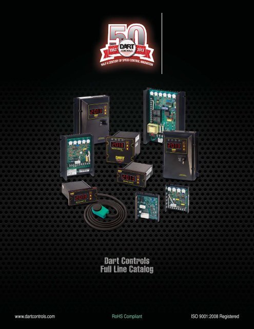
<strong>Dart</strong> <strong>Controls</strong><br />
<strong>Full</strong> Line <strong>Catalog</strong><br />
www.dartcontrols.com RoHS Compliant ISO 9001:2008 Registered
<strong>Dart</strong> Delivers What You Want…<br />
When You Need It!<br />
Since 1963, <strong>Dart</strong> <strong>Controls</strong> has<br />
been designing and manufacturing<br />
variable speed drives, controls,<br />
and accessories for electric<br />
motors in our Zionsville,<br />
Indiana facility.<br />
Our Mission is to lead<br />
the market in development<br />
of technologically advanced<br />
variable speed motor controls<br />
and accessory products while<br />
maintaining our commitment to customers,<br />
employees and owners.<br />
Our Passion is to develop or<br />
make available for sale the broadest<br />
range of products possible to<br />
meet customer’s<br />
variable speed<br />
drive and motor<br />
requirements. We<br />
listen to customers<br />
and when<br />
needed, we will<br />
modify existing or add a new design<br />
to our product offering. We also<br />
leverage our industry relationships to<br />
make available for sale<br />
related products (AC<br />
drives, motors and gear<br />
reducers for example)<br />
from manufacturers who<br />
share our passion for excellence<br />
and value.<br />
This Total Solutions<br />
Provider approach allows us to deliver<br />
Total Value to our customers.<br />
DART DELIVERS!<br />
PUT US TO THE TEST<br />
All information contained in this<br />
catalog is intended to be correct,<br />
however information and data in<br />
this catalog are subject to change<br />
without notice. <strong>Dart</strong> <strong>Controls</strong>, Inc.<br />
(DCI) makes no warranty of any kind<br />
with regard to this information or<br />
data. Further, DCI is not responsible<br />
for any omissions or errors or<br />
consequential damage caused by<br />
the user of the product. DCI reserves<br />
the right to make manufacturing<br />
changes which may not be included<br />
in this catalog.<br />
1963<br />
2013<br />
HALF A CENTURY OF SPEED CONTROL INNOVATION<br />
P.O. Box 10, 5000 W. 106th Street, Zionsville, Indiana 46077<br />
Phone: (317) 873-5211 FAX: (317) 873-1105<br />
www.dartcontrols.com<br />
ISO 9001:2008 REGISTERED RoHS Compliant<br />
2
TABLE OF CONTENTS<br />
PAGE<br />
SCR DC SPEED CONTROLS (1/50–3 Horsepower) 4–13<br />
500 Series<br />
250 Series<br />
130 Series<br />
125 Series<br />
15 Series<br />
Voltage Signal Isolator<br />
DIGITAL DC SPEED CONTROLS (1/50–2 Horsepower) 14–19<br />
MD Series<br />
MD plus Series<br />
MD II Series<br />
SMART SPEED POT CONTROL ACCESSORIES 20–25<br />
Accu-Set Series<br />
Accu-Set plus Series<br />
Accu-Set II Series<br />
DC BRUSHLESS MOTOR SPEED CONTROLS 26–31<br />
700/Commutrol Series<br />
BATTERY OPERATED MOTOR SPEED CONTROLS 32–33<br />
65 Series<br />
FIELD PROGRAMMABLE DIGITAL TACHOMETERS 34–36<br />
DM8000 Series<br />
DP4 Series<br />
SPEED SENSORS 37–40<br />
PU-E Pick-up Series<br />
Optical Pick-up Series<br />
CF Pick-up Series<br />
MPU-A Pick-up Series<br />
VARIABLE AC VOLTAGE SUPPLIES 41<br />
55AC Series and AC03 Series<br />
MASTER SPEED CONTROL 42<br />
STANDARD STOCK DC MOTORS (1/4–2.0 Horsepower) 43<br />
Stock DC Motors<br />
APPLICATION HIGHLIGHTS 44–46<br />
DEFINITION OF TERMS 47<br />
www.dartcontrols.com<br />
3
500 Series<br />
Variable Speed Control<br />
NEMA 4/12<br />
“RC” Chassis<br />
Washdown Duty<br />
cULus Recognized<br />
<strong>Dart</strong>’s most fully featured<br />
analog DC speed control is<br />
reliable, versatile, and economical.<br />
Rated to 3 horsepower, it provides<br />
many standard features typically<br />
offered as options.<br />
The <strong>Dart</strong> 500 Series control<br />
combines advanced engineering<br />
design, quality component selection<br />
and rigorous quality control to deliver<br />
an excellent off-the-shelf SCR control.<br />
Dependable, time-proven circuitry<br />
offers performance characteristics<br />
previously available only in more<br />
costly controls.<br />
MADE IN THE<br />
<br />
While providing a wide range<br />
of standard features, many options<br />
quickly and easily extend the 500<br />
Series’ capabilities to meet specific<br />
application requirements.<br />
An integral part of a distinguished<br />
line of quality products, the 500 Series<br />
is representative of <strong>Dart</strong>’s continuing<br />
effort to provide reliable, versatile<br />
controls to the OEM, distributor, and<br />
the industrial markets.<br />
Speed Potentiometer<br />
Kit Included<br />
4 www.dartcontrols.com
500 SERIES STANDARD FEATURES<br />
<br />
<br />
<br />
<br />
<br />
<br />
<br />
<br />
<br />
<br />
<br />
<br />
<br />
<br />
knob included<br />
<br />
<br />
remote switching of AC power with low current momentary<br />
contacts. Prevents automatic restart after interruption of<br />
AC power.<br />
<br />
<br />
<br />
<br />
<br />
<br />
1000 RPM)<br />
<br />
<br />
<br />
<br />
<br />
<br />
500 SERIES SELECTION GUIDE<br />
H.P. CHASSIS ENCLOSED CHASSIS WITH<br />
RANGE “C” “RE” RELAY “RC”<br />
115 VAC Single Phase Input, 0-90 VDC Output 1<br />
<br />
1.5 533BC Available in chassis only, limited options available.<br />
230 VAC Single Phase Input, 0-180 VDC Output<br />
<br />
3.0 533BC Available in chassis only, limited options available.<br />
Horsepower settings are adjustable, see installation manual. Control is tested<br />
<br />
<br />
horsepower rating.<br />
DIMENSIONAL SPECIFICATIONS<br />
MODEL WIDTH LENGTH DEPTH WEIGHT<br />
English (inches)<br />
<br />
<br />
Metric (centimeters)<br />
Chassis 17.02 22.86 5.08 1134 gm.<br />
Enclosed 17.02 25.40 12.07 1422 gm.<br />
OPERATING CONDITIONS<br />
Temperature .......................................................... <br />
AC Input Voltage ................................... <br />
Input Frequency .............................................................<br />
ELECTRICAL SPECIFICATIONS AC INPUT 50/60 HZ<br />
115 VAC Single Phase Input, 0-90 VDC Output<br />
MAX. AC<br />
MAX. ARM*<br />
H.P. AMPS KVA AMPS DC<br />
1/8 1.8 0.22 1.4<br />
1/6 2.6 0.31 2.1<br />
1/4 3.5 0.42 2.7<br />
1/3 4.4 0.53 3.4<br />
1/2 6.5 0.78 5.0<br />
3/4 9.3 1.12 7.2<br />
1.0 13.2 1.58 10.2<br />
1.5 21.5 2.57 14.7<br />
230 VAC Single Phase Input, 0-180 VDC Output<br />
MAX. AC<br />
MAX. ARM*<br />
H.P. AMPS KVA AMPS DC<br />
1/4 1.8 0.42 1.4<br />
1/3 2.2 0.53 1.7<br />
1/2 3.3 0.78 2.5<br />
3/4 4.8 1.15 3.7<br />
1.0 6.5 1.56 5.0<br />
1.5 9.7 2.33 7.5<br />
2.0 12.9 3.10 9.9<br />
3.0 22.0 5.30 15.0<br />
<br />
POPULAR OPTIONS<br />
-5 option<br />
OPTION DESCRIPTION<br />
-36M option<br />
OPTION<br />
SUFFIX<br />
Jog (enclosed only) ...................................................................<br />
........................<br />
........................................<br />
Ten turn speed pot and dial plate (chassis only) ....................<br />
..................... <br />
NEMA 4/12 Enclosure .....................................................Standard<br />
<br />
Direction controlled with SPDT switch, relay contact (dry contact<br />
switching), or NPN open collector. Once direction change is initiated,<br />
cannot be aborted until motor stops; prevents relay contact welding<br />
(available through 2 H.P.)<br />
120 VAC ....................................................................... 1<br />
240 VAC ....................................................................... 1<br />
Other options are available, please consult factory for your requirement.<br />
* Field installable on chassis version only.<br />
<br />
www.dartcontrols.com<br />
5
250 Series<br />
Variable Speed Control<br />
Chassis<br />
NEMA 4/12<br />
Washdown Duty<br />
Speed Potentiometer<br />
Kit Included<br />
cULus Listed<br />
MADE IN THE<br />
<br />
The 250 Series offers superb<br />
flexibility, reliability, and value. A<br />
general purpose, economical control<br />
rated to 2 horsepower, it provides<br />
the ultimate in standard features and<br />
versatility including: dual voltage<br />
(120/240 VAC), adjustable H.P.<br />
settings, packaged power bridge,<br />
barrier terminal strip, fully ratedno<br />
auxiliary heatsink required,<br />
and chassis or NEMA 4/12 enclosure.<br />
Many options further extend<br />
the 250’s capabilities.<br />
A logical, easily accessible layout<br />
simplifies installation and adjustment.<br />
Clean design, quality components<br />
and careful assembly are trademarks<br />
of <strong>Dart</strong> <strong>Controls</strong>.<br />
History Note–1963<br />
The Easy<br />
Bake® oven<br />
was the #1<br />
toy seller<br />
<strong>Dart</strong><br />
<strong>Controls</strong><br />
was<br />
incorporated<br />
6 www.dartcontrols.com
250 SERIES STANDARD FEATURES<br />
<br />
<br />
<br />
<br />
<br />
±<br />
<br />
<br />
<br />
<br />
<br />
<br />
<br />
<br />
<br />
<br />
<br />
<br />
ungrounded analog input signal (0–12 VDC)<br />
<br />
<br />
<br />
<br />
200V for 240 VAC input)<br />
<br />
<br />
250 SERIES SELECTION GUIDE<br />
H.P. RANGE CHASSIS “C” ENCLOSED “E”<br />
120 VAC Single Phase Input, 0-90 VDC Output<br />
<br />
<br />
240 VAC Single Phase Input, 0-180 VDC Output<br />
<br />
<br />
<br />
<br />
its category.<br />
DIMENSIONAL SPECIFICATIONS<br />
MODEL WIDTH LENGTH DEPTH WEIGHT<br />
English (inches)<br />
<br />
<br />
Metric (centimeters)<br />
Chassis 14.1 17.78 4.14 404 gm.<br />
Enclosed 14.1 18.42 6.98 486 gm.<br />
OPERATING CONDITIONS<br />
Temperature .......................................................... <br />
AC Input Voltage ................................... <br />
Input Frequency .............................................................<br />
ELECTRICAL SPECIFICATIONS AC INPUT 50/60 HZ<br />
120 VAC Single Phase Input, 0-90 VDC Output<br />
MAX. AC<br />
MAX. ARM*<br />
H.P. AMPS KVA AMPS DC<br />
1/50 0.5 0.06 0.4<br />
1/20 1.0 0.12 0.8<br />
1/8 2.0 0.24 1.6<br />
1/4 3.5 0.42 2.7<br />
1/3 4.4 0.53 3.4<br />
1/2 6.5 0.78 5.0<br />
3/4 9.3 1.12 7.2<br />
1 13.2 1.58 10.2<br />
240 VAC Single Phase Input, 0-180 VDC Output<br />
MAX. AC<br />
MAX. ARM*<br />
H.P. AMPS KVA AMPS DC<br />
1/4 1.8 0.42 1.4<br />
1/3 2.2 0.53 1.7<br />
1/2 3.3 0.78 2.5<br />
3/4 4.8 1.15 3.7<br />
1 6.5 1.56 5.0<br />
1 1/2 9.7 2.33 7.5<br />
2 12.9 3.10 9.9<br />
For dual voltage 250 series, use table for the input voltage you are using.<br />
<br />
POPULAR OPTIONS<br />
-5 option board<br />
OPTION DESCRIPTION<br />
-55G2 option<br />
boards<br />
OPTION<br />
SUFFIX<br />
NEMA 4X Enclosure .................................................................<br />
........................<br />
......................................... 1<br />
Decel equals Accel time .........................................................<br />
<br />
(center blocked, no Dynamic Brake–enclosed only) ...................<br />
<br />
..............................................................<br />
Torque control (enclosed only) ..............................................<br />
Isolated voltage follower (120/240 VAC input) – controls speed from<br />
any external grounded or ungrounded signal: 0-5 VDC thru 0-250 VDC<br />
adjustable (chassis only) ....................................................... <br />
........................... 1<br />
Other options are available, please consult factory for your requirement.<br />
* Field installable<br />
<br />
www.dartcontrols.com<br />
7
130 Series Reversing Control<br />
for PM and Shunt Wound DC Motors<br />
through 2 HP<br />
cULus Listed<br />
MADE IN THE<br />
<br />
Speed Potentiometer<br />
Kit Included<br />
Instant reversing, quick stopping,<br />
rapid cycling… The 130<br />
Series reversing control outperforms<br />
other dynamic braking and<br />
reversing controls by utilizing<br />
<strong>Dart</strong>’s unique zero-speed detect<br />
and dynamic braking circuits.<br />
These circuits eliminate the<br />
contact arcing and failed braking<br />
problems associated with other<br />
reversing and dynamic braking<br />
controls. <strong>Dart</strong>’s zero speed detect<br />
circuit also eliminates motor plug<br />
reversing problems.<br />
In the event of a power loss<br />
or emergency stop condition, the<br />
130 Series control will drop into a<br />
dynamic brake condition to safely<br />
and quickly bring the motor to a<br />
stop and remain there until power<br />
is reapplied and a run condition<br />
is recognized.<br />
History Note–1968<br />
UCLA wins<br />
men's NCAA®<br />
basketball<br />
title (again)<br />
Silicon<br />
Controlled<br />
Rectifier<br />
(SCR)<br />
patented<br />
8 www.dartcontrols.com
130 SERIES STANDARD FEATURES<br />
<br />
<br />
<br />
<br />
<br />
<br />
<br />
<br />
<br />
<br />
<br />
<br />
<br />
<br />
VAC input or 200V for 240 VAC input)<br />
<br />
<br />
<br />
130 SERIES OPERATING CONDITIONS<br />
Temperature ........................................................... <br />
AC Input Voltage ................................... <br />
Input Frequency ..............................................................<br />
TYPICAL APPLICATIONS<br />
<br />
<br />
<br />
<br />
<br />
<br />
<br />
130 SERIES MODEL NUMBERS AND RATINGS<br />
INPUT OUTPUT CYCLE<br />
MODEL VOLTAGE HP RANGE AMPS DC RATE<br />
<br />
<br />
<br />
<br />
<br />
<br />
<br />
<br />
* Up to 10 amps continuous output current at 1 Hp 90VDC with suitable external heat sink.<br />
** Up to 10 amps continuous output current at 2 Hp 180VDC with suitable external heat sink.<br />
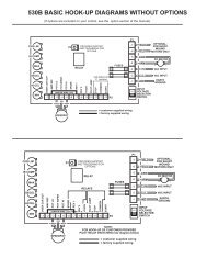
130 SERIES MECHANICAL SPECIFICATIONS, ADJUSTMENTS AND HOOK-UPS<br />
130 Series Hook-up<br />
4.063<br />
130 Series HC Models<br />
130 Series LC Models<br />
All dimensions in inches<br />
www.dartcontrols.com<br />
9
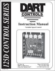
125 Series<br />
Variable Speed DC Control<br />
125DV-C<br />
Speed Potentiometer<br />
Kit Included<br />
cULus Recognized<br />
MADE IN THE<br />
<br />
The 125 Series is a compact,<br />
cost efficient, reliable control for<br />
PM, shunt wound, and universal<br />
motors that incorporates up-to-date<br />
design and engineering into a<br />
compact package.<br />
Installation and field adjustments<br />
are facilitated using a barrier type<br />
terminal strip and large, easily<br />
adjusted trimpots. Adjustable horsepower<br />
range.<br />
The 123D-C model operates on a<br />
low input voltage of 24/36 VAC with<br />
an output of 150mA–5.5 ADC<br />
Standard features include an<br />
inhibit circuit for start-stop operation<br />
and 1% speed regulation over<br />
a 50:1 speed range. Dual voltage<br />
120/240VAC or 24/36VAC models<br />
are available.<br />
Long life and quality are assured<br />
by 100% full load testing.<br />
The 125 Series is ideal for applications<br />
such as: office machinery, conveyors,<br />
office packaging equipment,<br />
printers, process equipment, centrifuges,<br />
and exercise equipment.<br />
History Note–1973<br />
Streaking is<br />
all the rage,<br />
for some<br />
reason<br />
<strong>Dart</strong><br />
introduces<br />
first SCR<br />
control for<br />
industrial<br />
use<br />
10 www.dartcontrols.com
125 SERIES STANDARD FEATURES<br />
<br />
<br />
<br />
<br />
<br />
±<br />
<br />
<br />
<br />
<br />
<br />
<br />
<br />
<br />
<br />
<br />
<br />
supplying ungrounded analog input signal (0–12 VDC)<br />
<br />
<br />
<br />
<br />
125 SERIES SELECTION GUIDE<br />
H.P. RANGE MODEL INPUT OUTPUT<br />
<br />
}<br />
<br />
<br />
<br />
<br />
}<br />
<br />
<br />
<br />
from 5.5 amps DC to 10.0 amps DC.<br />
<br />
<br />
OPERATING CONDITIONS<br />
Temperature .......................................................... <br />
AC Input Voltage ................................... <br />
Input Frequency .............................................................<br />
ELECTRICAL SPECIFICATIONS AC INPUT 50/60 HZ<br />
120 VAC Single Phase Input, 0-90 VDC Output<br />
MAX. AC<br />
MAX. ARM*<br />
H.P. AMPS KVA AMPS DC<br />
1/50 0.5 0.06 0.4<br />
1/20 1.0 0.12 0.8<br />
1/8 2.0 0.24 1.6<br />
1/4 3.5 0.42 2.7<br />
1/3 4.4 0.53 3.4<br />
1/2 6.5 0.78 5.0<br />
240 VAC Single Phase Input, 0-180 VDC Output<br />
MAX. AC<br />
MAX. ARM*<br />
H.P. AMPS KVA AMPS DC<br />
1/4 1.8 0.42 1.4<br />
1/3 2.2 0.53 1.7<br />
1/2 3.3 0.78 2.5<br />
3/4 4.8 1.15 3.7<br />
1 6.5 1.56 5.0<br />
<br />
DIMENSIONAL SPECIFICATIONS<br />
MODEL WIDTH HEIGHT DEPTH WEIGHT<br />
English (inches)<br />
<br />
Metric (centimeters)<br />
Chassis 9.20 10.80 3.30 227 gm.<br />
ADJUSTMENTS AND HOOK-UP<br />
MIN<br />
MAX<br />
IR COMP<br />
CUR LIM<br />
POPULAR OPTIONS<br />
-55G option<br />
-5 option<br />
OPTION DESCRIPTION<br />
INHIBIT<br />
SPEEDPOT LO<br />
SPEEDPOT WIPER<br />
SPEEDPOT HI<br />
+FIELD<br />
-ARM/-FIELD<br />
+ARM<br />
AC INPUT<br />
AC INPUT<br />
-2A option<br />
OPTION<br />
SUFFIX<br />
Electronic speed control interlock – when AC power to control is<br />
applied, prevents motor from starting until speedpot is first<br />
rotated to the zero position, then CW. Also, should AC power<br />
be interrupted then restored, prevents automatic restart .....................<br />
Independently adjustable linear accel and decel<br />
............................................................... <br />
...............................................<br />
..........................................<br />
.................................. <br />
...................................... <br />
<br />
(center blocked, no Dynamic Brake) ................................... <br />
Isolated voltage follower (120/240 VAC input)– controls speed<br />
from any external grounded or ungrounded signal: 0-5 VDC thru 0-250<br />
VDC adjustable ...................................................................... <br />
.............................. <br />
<br />
........................... <br />
Other options are available, please consult factory for your requirement.<br />
* Field installable<br />
-8<br />
-7<br />
-6<br />
-5<br />
-4<br />
-3<br />
-2<br />
-1<br />
P1<br />
www.dartcontrols.com<br />
11
15DV1A<br />
MADE IN THE<br />
<br />
cULus Recognized<br />
15DV-E<br />
15 Series<br />
Adjustable Speed DC Control<br />
15DV2A<br />
The 15 Series is a general purpose, economical variable speed<br />
control for small DC and universal motor applications featuring:<br />
dual input voltages of 12/24 VAC or 120/240 VAC with a DC output<br />
current rating of 2 Amps, adjustable trimpot settings, and quick<br />
connect terminal pins. The 15 Series is available in two compact<br />
panel mount styles and a NEMA 4/12 enclosed model.<br />
15 SERIES STANDARD FEATURES<br />
Dual voltage models of 12/24 VAC or 120/240 VAC input<br />
<br />
<br />
<br />
<br />
<br />
<br />
<br />
<br />
<br />
<br />
<br />
<br />
<br />
} Enclosed Model<br />
15 SERIES SELECTION GUIDE<br />
Suffix -1 and -2 refer to mounting configuration, see diagram below.<br />
MODEL DC OUTPUT INPUT OUTPUT<br />
CURRENT<br />
<br />
<br />
<br />
<br />
<br />
<br />
* Rating for D.C. Output Current can be increased from 2.0 to 4.0 amps w/suitable external heatsink<br />
(equiv. to 4” x 4” x .125” aluminum plate).<br />
DIMENSIONAL SPECIFICATIONS<br />
MODEL WIDTH HEIGHT DEPTH WEIGHT<br />
English (inches)<br />
<br />
<br />
<br />
Metric (centimeters)<br />
13DV1A/15DV1A 7.20 3.30 8.40 75 gm.<br />
13DV2A/15DV2A 7.20 3.90 8.40 83 gm.<br />
<br />
OPERATING CONDITIONS<br />
Temperature .......................................................... <br />
AC Input Voltage ................................... <br />
Input Frequency .............................................................<br />
ELECTRICAL SPECIFICATIONS AC INPUT 50/60 HZ<br />
MAXIMUM MAX.<br />
CONTINUOUS CONTINUOUS MAX<br />
MODEL AC AMPS ARM AMPS* HP<br />
12 VAC Single Phase Input, 0-11 VDC Output<br />
13DVA 2.6 2.0 1/40<br />
<br />
24 VAC Single Phase Input, 0-22 VDC Output<br />
13DVA 2.6 2.0 1/20<br />
<br />
120 VAC Single Phase Input, 0-90 VDC Output<br />
15DVA 2.6 2.0 1/6<br />
<br />
240 VAC Single Phase Input, 0-180 VDC Output<br />
15DVA 2.6 2.0 1/3<br />
<br />
* Minimum Armature Amps: 150mA D.C.<br />
HOOK-UP DIAGRAM<br />
HEATSINK DIMENSIONS AND STYLES<br />
.592<br />
.140<br />
.216<br />
.240<br />
2.500 +/-.050<br />
2.055<br />
.318 .178<br />
.203<br />
1.261<br />
.377 DIA.<br />
(1 HOLE)<br />
C L<br />
2.126<br />
2.326<br />
OPTION DESCRIPTION<br />
MAX<br />
IR COMP<br />
MIN<br />
.140 DIA.<br />
(2 PLACES)<br />
.750<br />
.230<br />
+ FIELD<br />
AC INPUT<br />
AC INPUT<br />
- FIELD<br />
- ARMATURE<br />
+ ARMATURE<br />
1 HOUSING<br />
(SIDE PROFILE)<br />
2 HOUSING<br />
OPTION<br />
SUFFIX<br />
Single pole AC switch integral with speedpot for<br />
120 VAC application only .................................................<br />
.............<br />
12 www.dartcontrols.com
VSI Series<br />
Voltage Signal Isolator*<br />
MADE IN THE<br />
<br />
The <strong>Dart</strong> VSI (voltage signal isolator) permits the user to control<br />
the output of a variable speed motor drive from any external<br />
grounded or ungrounded DC input signal. A single model accepts<br />
a wide range of input voltages (0-5 through 0-25VDC or 0-25<br />
through 0-250VDC). The GAIN trimpot is used to adjust the output<br />
of the VSI to full on when a full speed signal is applied to its<br />
input terminals. The VSI incorporates <strong>Dart</strong>’s unique feedback circuit,<br />
which virtually eliminates output changes due to the thermal<br />
drift of logic components. The VSI is packaged in an aluminum<br />
chassis mount housing and contains an on-board power supply<br />
for its logic circuit. An electrical isolation rating of 2500Vrms is<br />
achieved by the use of an optically isolated IC package.<br />
The <strong>Dart</strong> VSI can be used with virtually any motor speed control<br />
that has a speed reference circuit of +5 to +15VDC and an<br />
input impedance greater than 47K ohms. The output of the VSI<br />
is a filtered, pulse width modulated signal that is directly proportional<br />
to the input speed signal. The wide input range allows the<br />
VSI to follow signals as low as +0-5V logic levels and up to the<br />
180 VDC levels present at the armature leads of a 180 VDC motor.<br />
By simply connecting the input terminals across the armature<br />
leads of a “master motor”, you can use the VSI for master/follower<br />
operation. The addition of a scaling pot will provide for proportional<br />
follower operation.<br />
* By adding a resistor across signal input, VSI can function as<br />
a Current Signal Isolator.<br />
VSI SERIES SELECTION GUIDE<br />
MODEL<br />
<br />
SUPPLY VOLTAGE<br />
<br />
DIMENSIONAL SPECIFICATIONS<br />
WIDTH LENGTH DEPTH WEIGHT<br />
English<br />
<br />
Metric<br />
9.220 cm 10.795 cm 4.191 cm 277.3 gm<br />
VSI HOOK-UP CONFIGURATIONS<br />
AC INPUT<br />
DUAL VOLTAGE INPUT<br />
CONNECT TO<br />
SPEEDPOT INPUT<br />
OF MOTOR CONTROL{<br />
SIGNAL COMMON<br />
N.C.<br />
SIGNAL POSITIVE<br />
P3<br />
AC<br />
AC<br />
HI<br />
W<br />
LO<br />
COMMON<br />
+5V<br />
SIGNAL IN<br />
GAIN<br />
TRIMPOT<br />
STANDARD<br />
HOOK-UP<br />
P4<br />
-3<br />
-2<br />
-1<br />
JUMPER<br />
CLIP **<br />
CONNECT TO<br />
SPEEDPOT INPUT<br />
OF MOTOR CONTROL<br />
- ARM<br />
+ ARM<br />
www.dartcontrols.com<br />
MASTER<br />
MOTOR<br />
AC INPUT<br />
DUAL VOLTAGE INPUT<br />
250VDC<br />
MAX.<br />
{<br />
N.C.<br />
250K<br />
RATIO POT *<br />
(0-100% of Master)<br />
P3<br />
AC<br />
AC<br />
HI<br />
W<br />
LO<br />
COMMON<br />
+5V<br />
SIGNAL IN<br />
P4<br />
-3<br />
-2<br />
-1<br />
JUMPER<br />
CLIP **<br />
GAIN<br />
TRIMPOT<br />
FOLLOWER MODE<br />
HOOK-UP<br />
NOTES:<br />
*<br />
**<br />
If ratio of Master is NOT needed,<br />
delete the 250K pot and connect<br />
+Armature directly to Signal<br />
Input.<br />
Jumper clip is used to select<br />
input voltage range. When<br />
installed from P4-1 to P4-2, the<br />
range is 0-25VDC thru 0-250VDC;<br />
when installed from P4-2 to P4-3,<br />
range is 0-5VDC thru 0-25VDC.<br />
13
MD3E<br />
MD3P<br />
MD Series<br />
Digital Closed Loop DC Speed Control<br />
The MD Series is a compact, programmable DC speed control<br />
with digital closed loop feedback and LED display for DC<br />
motors rated to 2 horsepower. An on-board microprocessor with<br />
non-volatile memory, coupled with sophisticated internal software,<br />
makes <strong>Dart</strong>’s Micro-Drive the ultimate value in accuracy<br />
and control.<br />
Friendly front-panel field programming permits customizing<br />
the MD for specific applications. The MD can be set to<br />
display the target speed directly in RPM, FPM, GPM, process<br />
time, or any other engineering unit. Programmable parameters<br />
include maximum and minimum set speed, decimal points, and<br />
operating mode (master or follower).<br />
The Micro-Drive is simple to operate: set the desired RPM,<br />
rate, or time in the large 1/2" LED display by depressing the “Up”<br />
and “Down” pushbuttons on the front panel. Settings can be one<br />
digit at a time or fast sweep. The Micro-Drive settings are exact<br />
and repeatable. It will precisely control speed to ±1/2 RPM of set<br />
speed, long term. No calibrations of the control are necessary.<br />
The MD10P and MD3P have 1/8 DIN and 1/4 DIN<br />
industry standard cutout dimensions respectively, providing easy<br />
panel installations.<br />
TYPICAL APPLICATIONS<br />
<br />
<br />
<br />
processes, and heat shrink packaging<br />
<br />
<br />
<br />
<br />
<br />
MD10P<br />
MD SERIES STANDARD FEATURES<br />
<br />
<br />
<br />
<br />
<br />
<br />
<br />
<br />
future use<br />
<br />
<br />
<br />
new settings<br />
<br />
lockout capability<br />
<br />
<br />
<br />
<br />
and intensity<br />
<br />
<br />
<br />
<br />
85–265 VAC<br />
<br />
<br />
<br />
form C relay<br />
<br />
OPTION DESCRIPTION<br />
MADE IN THE<br />
<br />
OPTION<br />
SUFFIX<br />
Provision for remote pushbutton switches ...............................<br />
...............................................................................<br />
Pluggable terminal strip ........................................................... <br />
...................................................<br />
14 www.dartcontrols.com
Tach<br />
MD SERIES SELECTION GUIDE<br />
MODEL MAX. ARM MAX<br />
NUMBER DC AMPS H.P. INPUT OUTPUT<br />
<br />
<br />
MOUNTING SPECIFICATIONS<br />
CONTROLS Page<br />
Ite<br />
Valu<br />
m<br />
4.000"<br />
Tach<br />
ENTER<br />
4.000"<br />
3.622"<br />
MD10P<br />
HOUSING DEPTH<br />
4.625"<br />
0.885"<br />
1.770"<br />
<br />
<br />
1/8 DIN<br />
MICRO-DRIVE<br />
.140" x 2<br />
PANEL CUT-OUT<br />
MD3E <br />
<br />
<br />
<br />
<br />
-Sensor must have minimum output current of 10 mA.<br />
-Drive includes supply for external sensor of 5VDC @50 mA max.<br />
-Shipped set for 0-2400 RPM with one pulse per revolution.<br />
MICRO-DRIVE<br />
CONTROLS<br />
ENTER<br />
.140" x 4<br />
3.622<br />
MD3P<br />
HOUSING DEPTH<br />
4.625"<br />
PANEL CUT-OUT<br />
0.811"<br />
3.622"<br />
2.000"<br />
OPERATING SPECIFICATIONS<br />
Temperature ........................................................... <br />
AC input voltage ........................................................ 85–265 VAC<br />
Input frequency ...............................................................<br />
Overload capacity ............................................ <br />
Transducer signal input ....................................... <br />
...........................................5 VDC, 50mA<br />
DIMENSIONAL SPECIFICATIONS<br />
MODEL WIDTH HEIGHT DEPTH<br />
MD10P inches (millimeters)<br />
Housing 3.620 (91.95) 1.656 (42.06) 4.625 (117.47)<br />
Lens 4.539 (115.29) 2.289 (58.13) 0.375 (9.52)<br />
MD3P inches (millimeters)<br />
Housing 3.620 (91.95) 3.497 (88.82) 4.625 (117.47)<br />
Lens 4.539 (115.29) 4.179 (106.15) 0.375 (9.52)<br />
1/4 DIN<br />
WIRING DIAGRAMS<br />
MD3E<br />
P1-1<br />
P1-2<br />
P1-3<br />
P1-4<br />
P1-5<br />
P1-6<br />
P1-7<br />
P1-8<br />
P1-9<br />
P1-10<br />
P1-11<br />
P1-12<br />
N<br />
L<br />
-A<br />
+A<br />
COM<br />
+5V<br />
S1<br />
S2<br />
NO<br />
C<br />
NC<br />
IN1<br />
-ARM<br />
+ARM<br />
COMMON<br />
+5VDC<br />
SIGNAL<br />
*Jog Input<br />
Ground Lug<br />
AC INPUT<br />
AC INPUT} 85-265VAC<br />
black<br />
red<br />
white<br />
Alarm Output - Normally Open<br />
Alarm Output - Common<br />
Alarm Output - Normally Closed<br />
*INHIBIT<br />
User Input 1<br />
MOTOR<br />
COM (P1-5)<br />
}<br />
Form<br />
* P1-8 & P1-12 user input may be programmed<br />
for a number of functions. Including (jog, inhibit, etc.)<br />
C<br />
Relay Output<br />
(Programmable)<br />
PICK-UP MOUNTED<br />
TO MOTOR SHAFT<br />
(Mounts on rotating<br />
end shaft with 10-32<br />
tapped hole, 1/2" deep)<br />
MOUNTING SPECIFICATIONS MD3E<br />
5.530<br />
Page Item Valu Tach<br />
ENTER<br />
7/32" TYP.<br />
(4 SLOTS)<br />
.350 DEEP<br />
MDP<br />
MASTER<br />
P1-1<br />
P1-2<br />
P1-3<br />
P1-4<br />
P1-5<br />
P1-6<br />
P1-7<br />
P1-8<br />
P1-9<br />
P1-10<br />
P1-11<br />
P1-12<br />
AC INPUT<br />
FUSE<br />
N<br />
MD10P = 7.5 Amp* }85-265VAC<br />
MD3P = 15 Amp*<br />
L<br />
AC INPUT<br />
-A<br />
-ARM<br />
+A<br />
+ARM<br />
MOTOR<br />
COM<br />
COMMON black<br />
+5V<br />
+5VDC red<br />
S1<br />
SIGNAL white<br />
S2<br />
**Jog Input<br />
NO Alarm Output - Normally Open<br />
C Alarm Output - Common<br />
Form C<br />
Relay Output<br />
NC Alarm Output - Normally Closed}<br />
(Programmable)<br />
IN1<br />
User Input 1<br />
**INHIBIT<br />
PICK-UP MOUNTED<br />
TO MOTOR SHAFT<br />
(Mounts on rotating<br />
end shaft with 10-32<br />
tapped hole, 1/2" deep)<br />
COM (P1-5)<br />
black<br />
CONTROLS<br />
* For AC inputs utilizing two hot lines, both inputs should be<br />
protected with appropriately sized fuses or circuit breakers.<br />
** P1-8 & P1-12 user input may be programmed<br />
for a number of functions. Including (jog, inhibit, etc.)<br />
white<br />
7.400<br />
ON<br />
OFF<br />
5.500<br />
.750<br />
MDP<br />
FOLLOWER<br />
P1-1<br />
P1-2<br />
P1-3<br />
P1-4<br />
P1-5<br />
P1-6<br />
P1-7<br />
P1-8<br />
P1-9<br />
P1-10<br />
P1-11<br />
P1-12<br />
N<br />
L<br />
FUSE<br />
MD10P = 7.5 Amp*<br />
MD3P = 15 Amp*<br />
-A<br />
-ARM<br />
+A<br />
+ARM<br />
COM<br />
COMMON<br />
+5V<br />
+5VDC<br />
S1<br />
SIGNAL 1<br />
S2<br />
NO Alarm Output - Normally Open<br />
C Alarm Output - Common<br />
NC Alarm Output - Normally Closed<br />
IN1<br />
User Input 1<br />
**INHIBIT<br />
SIGNAL 2<br />
COM (P1-5)<br />
AC INPUT<br />
}85-265VAC<br />
AC INPUT<br />
}<br />
MOTOR<br />
black<br />
red<br />
white<br />
Form C<br />
Relay Output<br />
(Programmable)<br />
FOLLOWER PICK-UP<br />
MOUNTED TO<br />
MOTOR SHAFT<br />
(Mounts on rotating<br />
end shaft with 10-32<br />
tapped hole, 1/2" deep)<br />
5.125 TYP.<br />
* For AC inputs utilizing two hot lines, both inputs should be<br />
protected with appropriately sized fuses or circuit breakers.<br />
** P1-8 & P1-12 user input may be programmed<br />
for a number of functions. Including (jog, inhibit, etc.)<br />
www.dartcontrols.com<br />
15
MD50E<br />
MD50P<br />
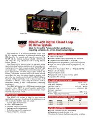
MD40P<br />
MADE IN THE<br />
<br />
MD Plus Series<br />
Digital Closed Loop DC Drive<br />
IDEAL FOR METERING PUMP AND OTHER APPLICATIONS<br />
REQUIRING AN ISOLATED 4-20MA INPUT/OUTPUT SIGNAL<br />
The MD plus is a field-programmable closed loop DC<br />
drive system employing an advanced velocity-form PID algorithm<br />
for accurate and responsive control. The MD plus system<br />
also features an optional isolated 4-20mA input and output<br />
for easy integration with existing Process Control systems.<br />
The MD plus system is ideally suited for metering pump<br />
applications by efficiently combining all of the application<br />
requirements into a single compact package. The MD plus<br />
system, when used with the OPT420 option, not only<br />
accepts a 4-20mA signal to control the pump speed,<br />
but it also provides a 4-20mA output signal back to the<br />
Process Control that is proportional to the actual running<br />
speed. Both the input and output signals are isolated from each<br />
other and from the control itself. The MD plus system also<br />
has two field-programmable Form C relay contacts that<br />
can be set to indicate a wide variety of conditions such as<br />
the pump is running, a “fault” condition exists, and many<br />
other events.<br />
The MD plus system is available in both enclosed and<br />
panel-mount versions. The MD50E version comes in a NEMA<br />
4X enclosure complete with an auto/off/manual switch on the<br />
cover. The 1/8 DIN MD40P and 1/4 DIN MD50P panel-mount<br />
versions come complete with a NEMA 4X rated faceplate, gasket<br />
kit, stainless steel mounting hardware, and connections for<br />
an external auto/manual switch.<br />
STANDARD FEATURES<br />
<br />
<br />
<br />
<br />
<br />
<br />
<br />
<br />
<br />
<br />
<br />
AVAILABLE OPTIONS<br />
<br />
<br />
<br />
OPERATING SPECIFICATIONS<br />
Ambient Temp .........................................................<br />
Line Input Frequency ......................................................<br />
Overload Capacity ........................................... <br />
Transducer Input ................................................. <br />
<br />
Power Supply ...........................................................5 VDC, 50mA<br />
.............................................. ± <br />
16 www.dartcontrols.com
MD plus SERIES SELECTION GUIDE<br />
MODEL MAX. ARM MAX<br />
NUMBER DC AMPS H.P. INPUT OUTPUT<br />
<br />
<br />
<br />
<br />
<br />
<br />
DIMENSIONS (INCHES)<br />
MODEL WIDTH HEIGHT DEPTH<br />
MD40P (1/8 DIN)<br />
Housing 3.620 1.656 4.625<br />
Lens 4.539 2.289 0.375<br />
MD50P (1/4 DIN)<br />
Housing 3.620 3.497 4.625<br />
Lens 4.539 4.179 0.375<br />
MD50E (NEMA 4 enclosed)<br />
Housing 3.620 3.497 4.625<br />
Lens 4.539 4.179 0.375<br />
APPLICATIONS<br />
The MD plus system is ideal in many process applications<br />
requiring a closed-loop DC variable speed drive with an optional<br />
isolated 4-20mA input and output.<br />
Typical applications include:<br />
• Waste water treatment<br />
• Chemical metering processes<br />
• Laboratory mixing equipment<br />
• Industrial auger/mixing equipment<br />
• Polymer injection processes<br />
OPT420 OPTION<br />
The OPT420 Option may be factory or field installed to any<br />
drive in the MD Plus Series. The 4-20mA output is Loop Powered,<br />
relying on another device in the loop for its power. Both the<br />
4-20mA input and output are individually isolated. A second relay<br />
output is available when this option is used to indicate alarm and<br />
status information.<br />
OPT420 OPTION WIRING DIAGRAM<br />
+<br />
-<br />
+<br />
-<br />
P6<br />
P3<br />
3<br />
2<br />
1<br />
6<br />
5<br />
4<br />
3<br />
2<br />
1<br />
MD50E DRIVE TYPICAL WIRING DIAGRAM<br />
OPT420<br />
SEE<br />
4-20mA HOOK-UP<br />
5A 250V<br />
Form C<br />
}<br />
OPT420 RELAY Output - Common<br />
OPT420 RELAY Output - Normally Open Relay Output<br />
(Programmable)<br />
OPT420 RELAY Output - Normally Closed<br />
Auto / Manual Switch<br />
(Open = Manual)<br />
- 4-20mA In (Black)<br />
WIRING DIAGRAM – MASTER/FOLLOWER<br />
MD plus<br />
MASTER<br />
MD plus<br />
FOLLOWER<br />
P1-1<br />
P1-2<br />
P1-3<br />
P1-4<br />
P1-5<br />
P1-6<br />
P1-7<br />
P1-8<br />
P1-9<br />
P1-10<br />
P1-11<br />
P1-12<br />
MD<br />
MASTER<br />
P1-1<br />
P1-2<br />
P1-3<br />
P1-4<br />
P1-5<br />
P1-6<br />
P1-7<br />
P1-8<br />
P1-9<br />
P1-10<br />
P1-11<br />
P1-12<br />
P1-1<br />
P1-2<br />
P1-3<br />
P1-4<br />
P1-5<br />
P1-6<br />
P1-7<br />
P1-8<br />
P1-9<br />
P1-10<br />
P1-11<br />
P1-12<br />
N<br />
L<br />
-A<br />
+A<br />
COM<br />
+5V<br />
S1<br />
S2<br />
NO<br />
C<br />
NC<br />
IN1<br />
- 4-20mA Out (Black)<br />
-ARM<br />
+ARM<br />
COMMON<br />
+5VDC<br />
SIGNAL<br />
*Jog Input<br />
Ground Lug<br />
-<br />
4-20mA OUT<br />
(White)<br />
4-20mA IN (White)<br />
AC INPUT<br />
AC INPUT} 85-265VAC<br />
MOTOR<br />
black<br />
red<br />
white<br />
Alarm Output - Normally Open<br />
Alarm Output - Common<br />
Alarm Output - Normally Closed<br />
User Input 1<br />
**INHIBIT<br />
COM (P1-5)<br />
* For AC inputs utilizing two hot lines, both inputs should be<br />
protected with appropriately sized fuses or circuit breakers.<br />
** P1-8(S2) & P1-12(IN1) user input may be programmed<br />
for a number of functions, including (jog, inhibit, etc.)<br />
+<br />
+<br />
-<br />
Form C<br />
Relay Output<br />
}(Programmable)<br />
AC INPUT<br />
FUSE<br />
N MD40P = 7.5 Amp* }85-265VAC<br />
MD50P = 15 Amp*<br />
L<br />
AC INPUT<br />
-A<br />
-ARM<br />
+A<br />
+ARM<br />
MOTOR<br />
COM<br />
COMMON black<br />
+5V<br />
+5VDC red<br />
S1<br />
SIGNAL white<br />
S2<br />
**Jog Input<br />
NO Alarm Output - Normally Open<br />
C Alarm Output - Common<br />
Form C<br />
Relay Output<br />
}<br />
NC Alarm Output - Normally Closed (Programmable)<br />
IN1<br />
User Input 1<br />
**INHIBIT<br />
COM (P1-5)<br />
black<br />
white<br />
AC INPUT<br />
FUSE<br />
N MD40P = 7.5 Amp* }85-265VAC<br />
MD50P = 15 Amp*<br />
L<br />
AC INPUT<br />
-A<br />
-ARM<br />
+A<br />
+ARM<br />
MOTOR<br />
COM<br />
COMMON<br />
black<br />
+5V<br />
red<br />
+5VDC<br />
S1<br />
SIGNAL 1<br />
white<br />
S2<br />
SIGNAL 2<br />
NO Alarm Output - Normally Open<br />
C Alarm Output - Common<br />
Form C<br />
Relay Output<br />
NC<br />
}<br />
Alarm Output - Normally Closed (Programmable)<br />
IN1<br />
User Input 1<br />
**INHIBIT<br />
COM (P1-5)<br />
+ -<br />
9-36VDC<br />
EXCITATION<br />
SUPPLY<br />
PICK-UP MOUNTED<br />
TO MOTOR SHAFT<br />
(Mounts on rotating<br />
end shaft with 10-32<br />
tapped hole, 1/2" deep)<br />
CUSTOMER<br />
SUPPLIED<br />
IF NEEDED<br />
PICK-UP MOUNTED<br />
TO MOTOR SHAFT<br />
(Mounts on rotating<br />
end shaft with 10-32<br />
tapped hole, 1/2" deep)<br />
FOLLOWER PICK-UP<br />
MOUNTED TO<br />
MOTOR SHAFT<br />
(Mounts on rotating<br />
end shaft with 10-32<br />
tapped hole, 1/2" deep)<br />
www.dartcontrols.com<br />
17
MD30P<br />
MD20P<br />
MADE IN THE<br />
<br />
The MDII Series digital motor speed controls, employing<br />
an advanced 16-bit microprocessor, are designed for digital closed<br />
loop operation of up to 2 horsepower DC permanent magnet<br />
motors. This control features a true P-I-D algorithm, for extremely<br />
responsive and precise control over a wide variety<br />
of desired speeds and applications. The MDII Series is<br />
designed as a companion or direct replacement control to the MD<br />
Series, while offering expanded performance features.<br />
Set or actual speed is displayed directly in RPM, FPM,<br />
PROCESS TIME, or other engineering units. Field programming<br />
permits customizing specific operating parameters.<br />
The integrated RS485/RS422/RS232 serial interface port is<br />
perfect for monitoring or control using almost any computer or<br />
process controller. Units can even be attached in a Local Area<br />
Network, and can then be controlled and programmed either individually<br />
or all at once. Multiple programs allow the user to choose<br />
between a “menu” of up to six programmed configurations.<br />
The MDII series is the ultimate answer for precise, responsive,<br />
cost-effective and flexible closed loop motor speed control.<br />
COMMUNICATION FEATURES<br />
MD30E<br />
MDII Series<br />
Programmable Digital Closed Loop<br />
DC Speed Control with P-I-D and<br />
RS Communication<br />
<br />
<br />
<br />
<br />
<br />
<br />
via one cable. <strong>Controls</strong> can be individually programmed<br />
or integrated.<br />
<br />
<br />
be followed together over single RS485 twisted pair<br />
<br />
STANDARD FEATURES<br />
<br />
<br />
<br />
<br />
<br />
time, or other engineering units<br />
<br />
<br />
±1/2 RPM of set speed<br />
<br />
<br />
<br />
<br />
programmable parameters<br />
<br />
<br />
control target speed, current program or frequency generator<br />
output<br />
<br />
<br />
control units<br />
<br />
front panel lockout prevents accidental setting changes<br />
<br />
<br />
<br />
<br />
<br />
<br />
leader frequency.<br />
<br />
membrane seals faceplate from environment<br />
<br />
<br />
selected from the front panel via the up/down pushbutton<br />
switches<br />
PROGRAMMING FEATURES<br />
<br />
<br />
<br />
<br />
<br />
<br />
<br />
<br />
<br />
<br />
rate or time<br />
<br />
<br />
<br />
<br />
<br />
<br />
follower, Network Follower)<br />
<br />
<br />
<br />
<br />
18 www.dartcontrols.com
MDII SERIES SELECTION GUIDE<br />
MODEL MAX. ARM MAX<br />
NUMBER DC AMPS H.P. INPUT OUTPUT<br />
<br />
<br />
<br />
<br />
OPERATING SPECIFICATIONS<br />
Temperature ..........................................................<br />
AC Input Voltage ...................................................... 85–265 VAC<br />
Input Frequency ............................................................<br />
Overload Capacity .......................................... <br />
Transducer Signal Input .................<br />
WIRING DIAGRAM–MASTER/FOLLOWER<br />
<br />
<br />
<br />
<br />
<br />
-Sensor must have minimum output current of 10 mA.<br />
-Drive includes supply for external sensor of 5VDC @25 mA max.<br />
-Shipped set for 0-2400 RPM with one pulse per revolution.<br />
MDII<br />
MASTER<br />
P1-1<br />
P1-2<br />
P1-3<br />
P1-4<br />
P1-5<br />
P1-6<br />
P1-7<br />
P1-8<br />
P1-9<br />
P1-10<br />
P1-11<br />
P1-12<br />
FUSE*<br />
-ARM<br />
+ARM<br />
COMMON<br />
+5VDC<br />
SIGNAL 1<br />
UNUSED<br />
UNUSED<br />
UNUSED<br />
UNUSED<br />
black<br />
red<br />
white<br />
OPTIONAL<br />
INHIBIT<br />
SWITCH<br />
* MD20P = 7.5 Amp<br />
MD30P = 15 Amp<br />
AC AC INPUT} 85-265VAC<br />
MOTOR<br />
black<br />
white<br />
PICK-UP MOUNTED<br />
TO MOTOR SHAFT<br />
(Mounts on rotating<br />
end shaft with 10-32<br />
tapped hole, 1/2" deep)<br />
OPTION DESCRIPTION<br />
OPTION<br />
SUFFIX<br />
<br />
signal input (MD30E only) .......................................................<br />
....................................................<br />
...................................................<br />
Pluggable terminal strip ............................................................ <br />
WIRING DIAGRAM - MASTER<br />
MDII<br />
FOLLOWER<br />
P1-1<br />
P1-2<br />
P1-3<br />
P1-4<br />
P1-5<br />
P1-6<br />
P1-7<br />
P1-8<br />
P1-9<br />
P1-10<br />
P1-11<br />
P1-12<br />
FUSE*<br />
-ARM<br />
+ARM<br />
COMMON<br />
UNUSED<br />
UNUSED<br />
UNUSED<br />
+5VDC<br />
SIGNAL 1<br />
UNUSED<br />
OPTIONAL<br />
INHIBIT<br />
SWITCH<br />
AC AC INPUT} 85-265VAC<br />
black<br />
red<br />
white<br />
MOTOR<br />
FOLLOWER PICK-UP<br />
MOUNTED TO<br />
MOTOR SHAFT<br />
(Mounts on rotating<br />
end shaft with 10-32<br />
tapped hole, 1/2" deep)<br />
P1-1<br />
P1-2<br />
P1-3<br />
P1-4<br />
P1-5<br />
P1-6<br />
P1-7<br />
P1-8<br />
P1-9<br />
P1-10<br />
P1-11<br />
P1-12<br />
Page<br />
FUSE*<br />
-ARM<br />
+ARM<br />
COMMON<br />
+5VDC<br />
SIGNAL 1<br />
UNUSED<br />
UNUSED<br />
UNUSED<br />
UNUSED<br />
OPTIONAL<br />
INHIBIT<br />
SWITCH<br />
Item<br />
CONTROLS<br />
5.530<br />
Valu<br />
black<br />
red<br />
white<br />
COM (P1-5)<br />
Tach<br />
AC AC INPUT} 85-265VAC<br />
ENTER<br />
MOTOR<br />
MOUNTING SPECIFICATIONS - MD30E<br />
PICK-UP MOUNTED<br />
TO MOTOR SHAFT<br />
(Mounts on rotating<br />
end shaft with 10-32<br />
tapped hole, 1/2" deep)<br />
7/32" TYP<br />
(4 SLOTS)<br />
.350 DEEP<br />
<br />
fusing or switch needed.<br />
DIMENSIONAL SPECIFICATIONS<br />
MODEL WIDTH HEIGHT DEPTH<br />
MD20P inches (millimeters)<br />
Housing 3.620 (91.95) 1.656 (42.06) 4.625 (117.47)<br />
Lens 4.539 (115.29) 2.289 (58.13) 0.375 (9.52)<br />
MD30P inches (millimeters)<br />
Housing 3.620 (91.95) 3.497 (88.82) 4.625 (117.47)<br />
Lens 4.539 (115.29) 4.179 (106.15) 0.375 (9.52)<br />
MOUNTING SPECIFICATIONS - MD20P / MD30P<br />
CONTROLS<br />
Page<br />
Item<br />
4.000"<br />
Valu<br />
Tach<br />
MICRO-DRIVE II<br />
4.000"<br />
ENTER<br />
* MD20P = 7.5 Amp<br />
MD30P = 15 Amp<br />
Dia .140" x 2<br />
4.000"<br />
3.622"<br />
MD20P<br />
HOUSING DEPTH<br />
4.625"<br />
PANEL CUT-OUT<br />
4.000"<br />
3.622"<br />
.885"<br />
1.770"<br />
7.400<br />
5.500<br />
Page<br />
Item<br />
Valu<br />
Tach<br />
ENTER<br />
MD30P<br />
.811"<br />
ON<br />
OFF<br />
MICRO-DRIVE II<br />
HOUSING DEPTH<br />
4.625"<br />
3.622"<br />
2.000"<br />
CONTROLS<br />
PANEL CUT-OUT<br />
Dia .140" x 4<br />
.750<br />
5.125 TYP.<br />
www.dartcontrols.com<br />
19
Accu-Set Series<br />
Smart Speed Potentiometer<br />
for Improved AC or DC Drive<br />
System Performance<br />
MADE IN THE<br />
<br />
The Accu-Set is a compact, economical control that can<br />
be used with conventional AC, DC, or Brushless DC adjustable<br />
speed drive systems to provide an LED display of set<br />
speeds and precise, digital closed loop motor speed control.<br />
An on-board microprocessor with non-volatile memory coupled<br />
with sophisticated internal software makes <strong>Dart</strong>’s Accu-Set the<br />
ultimate in accuracy and control.<br />
Target speeds are displayed directly in RPM, FPM, GPM,<br />
process time, or any other engineering unit of measure.<br />
Friendly front-panel field programming permits customizing the<br />
Accu-Set to the exact specifications for each application; maximum<br />
and minimum set speed, decimal points or colon, operating<br />
mode (master or follower), and the constant which takes into account<br />
motor gear ratios.<br />
The Accu-Set is simple to operate… just set the desired RPM,<br />
rate, or time in the large 1/2" LED display by depressing the<br />
“up-down” pushbuttons, one digit at a time or fast sweep. The<br />
Accu-Set settings are exact and repeatable. It will precisely control<br />
speed to a remarkable ±1/2 RPM of set speed, long term.<br />
The panel mount unit is easy to install in the industry standard<br />
cutout dimensions of 1/8 DIN. All wiring connects directly to a<br />
European style terminal strip through the easy access rear panel.<br />
TYPICAL APPLICATIONS<br />
<strong>Dart</strong>’s Accu-Set design is ideal for providing the same precise<br />
closed loop control and digital readout as the MD Series Micro-<br />
Drive in new or retro-fit applications that use an AC, DC, or Brushless<br />
DC motor drive system.<br />
OPERATING SPECIFICATIONS<br />
Temperature .......................................................... -10° to +45° C<br />
AC input voltage .......................................................85–265 VAC<br />
Input frequency ...............................................................50/60 Hz<br />
Transducer signal input ......................................0-5 to 0-24 VDC<br />
On-board power supply ..........................................5 VDC, 50mA<br />
(for external sensors)<br />
History Note–1978<br />
The<br />
Unabomber<br />
sends<br />
his first<br />
"package"<br />
<strong>Dart</strong><br />
expands<br />
into<br />
worldwide<br />
markets<br />
20 www.dartcontrols.com
Tach<br />
ACCU-SET SERIES STANDARD FEATURES<br />
<br />
<br />
<br />
<br />
<br />
<br />
<br />
<br />
with parameter lockout capability<br />
<br />
(linear or accelerating)<br />
<br />
<br />
and intensity<br />
<br />
<br />
<br />
<br />
input from 85–265 VAC<br />
<br />
<br />
<br />
<br />
<br />
stored for future use<br />
<br />
<br />
<br />
ASP SELECTION GUIDE<br />
MODEL INPUT DISPLAY UNITS STD. SPEED RANGE<br />
ASP10 120/240 VAC Rate or Time Field Programmable*<br />
Requires <strong>Dart</strong> PU-E or other pick-up.<br />
* Shipped set for 0–2400 RPM with one pulse per revolution<br />
ASP<br />
ASTER<br />
ACCU-SET HOOK-UP- MASTER AND FOLLOWER<br />
M<br />
A<br />
S<br />
T<br />
E<br />
R<br />
P1-1<br />
P1-2<br />
P1-3<br />
P1-4<br />
P1-5<br />
P1-6<br />
P1-7<br />
P1-8<br />
P1-9<br />
P1-10<br />
P1-11<br />
P1-12<br />
ASP CONFIGURATIONS<br />
2 AMP AC AC INPUT} 85-265VAC<br />
HIGH OUTPUT<br />
Connect to the speedpot<br />
of the control being driven.<br />
WIPER OUTPUT } High must be positive<br />
voltage with respect to low.<br />
LOW OUTPUT<br />
COMMON<br />
+5VDC<br />
SIGNAL 1<br />
black<br />
red<br />
white<br />
SIGNAL 2<br />
Alarm Output - Normally Open<br />
Form C<br />
Relay output<br />
}<br />
Alarm Output - Common<br />
Alarm Output - Normally Closed (Programmable)<br />
* P1-9 signal input may be programmed for a number of functions. Incl (jog, inhibit, etc.)<br />
F<br />
O<br />
L<br />
ASP<br />
OLLOWER L<br />
O<br />
W<br />
E<br />
R<br />
P1-1<br />
P1-2<br />
P1-3<br />
P1-4<br />
P1-5<br />
P1-6<br />
P1-7<br />
P1-8<br />
P1-9<br />
P1-10<br />
P1-11<br />
P1-12<br />
COMMON<br />
+5VDC<br />
* Optional Inhibit Switch<br />
*<br />
black<br />
red<br />
SIGNAL 1<br />
white<br />
*<br />
SIGNAL 2<br />
Alarm Output - Normally Open<br />
Form C<br />
Relay output<br />
}<br />
Alarm Output - Common<br />
Alarm Output - Normally Closed (Programmable)<br />
black<br />
2 AMP AC AC INPUT} 85-265VAC<br />
HIGH OUTPUT Connect to the speedpot<br />
of the control being driven.<br />
WIPER OUTPUT } High must be positive<br />
voltage with respect to low.<br />
LOW OUTPUT<br />
white<br />
PICK-UP MOUNTED<br />
TO MOTOR SHAFT<br />
(Mounts on rotating<br />
end shaft with 10-32<br />
tapped hole, 1/2" deep)<br />
FOLLOWER PICK-UP<br />
MOUNTED TO<br />
MOTOR SHAFT<br />
(Mounts on rotating<br />
end shaft with 10-32<br />
tapped hole, 1/2" deep)<br />
OPTION DESCRIPTION<br />
OPTION<br />
SUFFIX<br />
Provisions for remote pushbutton switches ...............................<br />
Pluggable terminal strip ............................................................ <br />
....................................................<br />
DIMENSIONAL SPECIFICATIONS<br />
MODEL WIDTH HEIGHT DEPTH<br />
ASP 10 inches (millimeters)<br />
Housing 3.620 (91.95) 1.656 (42.06) 4.625 (117.47)<br />
Lens 4.539 (115.29) 2.289 (58.13) 0.375 (9.52)<br />
FEED<br />
REEL<br />
PU-2E<br />
ASP10<br />
motor<br />
PICK-UP<br />
Constant rate control<br />
speed<br />
control<br />
TAKE UP<br />
REEL<br />
SPEED<br />
CONTROL<br />
Ideal for maintaining precise SCR speed<br />
load regulation<br />
MOTOR<br />
ASP10<br />
MOUNTING SPECIFICATIONS<br />
4.000"<br />
4.000"<br />
3.622"<br />
speed<br />
control<br />
motor<br />
PU-2E<br />
ASP10<br />
speed<br />
control<br />
motor<br />
PU-2E<br />
CONTROLS<br />
Page<br />
Ite<br />
m<br />
Valu<br />
Tach<br />
ENTER<br />
ASP10<br />
HOUSING DEPTH<br />
4.625"<br />
0.885"<br />
1.770"<br />
Follower motor as % of master motor speed<br />
MICRO-DRIVE<br />
ACCU-SET<br />
.140" x 2<br />
PANEL CUT-OUT<br />
PU-2E<br />
motor<br />
speed<br />
control<br />
ASP10<br />
ASP10<br />
speed<br />
control<br />
motor<br />
PU-2E<br />
PU-2E<br />
motor<br />
speed ASP10<br />
control<br />
System for mixing and blending ratio control<br />
www.dartcontrols.com<br />
21
ASP Plus Series<br />
Smart Speed Pot for Any * Drive<br />
*must accept a 3-wire speed pot input<br />
Performance matched with<br />
<strong>Dart</strong>'s PU Series Encoder<br />
MADE IN THE<br />
<br />
The ASP PLUS Series is the<br />
latest development from <strong>Dart</strong> in the<br />
area of SMART speed pots.<br />
A SMART speed pot is:<br />
• Digital<br />
• Programmable<br />
• Closed-loop<br />
• Multi-function<br />
• Multi-mode<br />
The ASP PLUS is ideal for<br />
applications where a remote PLC/<br />
SCADA system sends the motor<br />
drive a set speed.<br />
History Note–1980<br />
Rubik's Cube,<br />
Pac-Man,<br />
J.R. Ewing<br />
(Dallas)<br />
<strong>Dart</strong><br />
introduces the<br />
Micro-Drive<br />
digital DC<br />
speed control<br />
The ASP PLUS works in con-<br />
junction with any drive by providing<br />
an isolated input for the PLC/SCADA<br />
command, using encoder feedback<br />
closes the motor loop to maintain tight<br />
speed regulation, and sends analog<br />
or serial communication data back<br />
to the supervisory system to verify<br />
actual motor speed. Along with motor<br />
not running indication, remote stop<br />
and Auto/Manual control modes the<br />
ASP PLUS packs all these features<br />
in one small package eliminating<br />
installation space and labor costs.<br />
The ASP PLUS is a real problem<br />
solver for plant maintenance,<br />
system integrator and OEM equipment<br />
designers.<br />
22 www.dartcontrols.com
ASP PLUS STANDARD FEATURES<br />
<br />
to suit your process control needs<br />
<br />
to accommodate a wide variety of I/O<br />
±1/2 RPM of<br />
set speed or equivalent<br />
<br />
impractical or undesired<br />
<br />
when power has been removed<br />
<br />
<br />
options, alarm options, and more<br />
<br />
<br />
<br />
<br />
automatically adjusts as needed.<br />
<br />
industrial environments<br />
<br />
<br />
<br />
at least 3mA<br />
<br />
<br />
<br />
<br />
Jog functionality<br />
<br />
(colon displayed in Time mode)<br />
<br />
Polycarbonate membrane and gasket (which are included) meet<br />
NEMA 4X standards when used with NEMA 4X enclosures<br />
<br />
block available<br />
<br />
<br />
<br />
<br />
<br />
<br />
Gallons per Second, etc.<br />
<br />
<br />
<br />
ASP PLUS SELECTION GUIDE<br />
MODEL INPUT ENCODER 4-20mA<br />
@ 50-60HZ REQUIRED? OUTPUT?<br />
<br />
<br />
DIMENSIONAL SPECIFICATIONS<br />
MODEL WIDTH HEIGHT DEPTH<br />
ASP40/ASP40-420 English (inches)<br />
Housing 3.620 1.656 4.625<br />
Lens 4.539 2.289 0.375<br />
ASP40/ASP40-420 Metric (millimeters)<br />
Housing 91.95 42.06 117.47<br />
Lens 115.29 58.14 9.52<br />
SPECIFICATIONS<br />
Signal Input Voltage Range .................................. 5VDC to 24VDC<br />
<br />
<br />
Speed Pickup<br />
Input Frequency (S1 and S2 Inputs) ..........................0 – 600,000<br />
<br />
<br />
Display Range .........................................................0.001 – 9,999<br />
"Engineering Units” .......................User Programmable, any Units<br />
Sensor / Pickup Power Supply ................................... <br />
ASP40 Isolated Alarm Relay Output Rating .............<br />
OPT420 Isolated Alarm Relay Output Rating .............<br />
Voltage Difference<br />
between PotLo and PotHi Inputs ....................... 2VDC to 24VDC<br />
<br />
voltage range ...................<br />
OPERATING CONDITIONS<br />
Temperature .......................................................... <br />
us<br />
ASP PLUS HOOK-UP– MASTER AND FOLLOWER<br />
M<br />
A<br />
S<br />
T<br />
E<br />
R<br />
P1-1<br />
P1-2<br />
P1-3<br />
P1-4<br />
P1-5<br />
P1-6<br />
P1-7<br />
P1-8<br />
P1-9<br />
P1-10<br />
P1-11<br />
P1-12<br />
2 AMP AC AC INPUT} 85-265VAC<br />
HIGH OUTPUT<br />
Connect to the speedpot<br />
of the control being driven.<br />
WIPER OUTPUT } High must be positive<br />
voltage with respect to low.<br />
LOW OUTPUT<br />
COMMON black<br />
red<br />
+5VDC<br />
SIGNAL 1 white<br />
*<br />
SIGNAL 2<br />
Alarm Output - Normally Open<br />
Alarm Output - Common<br />
Alarm Output - Normally Closed<br />
Form C<br />
Relay output<br />
} (Programmable)<br />
signal input may be programmed for a number of functions. Incl (jog, inhibit, etc.)<br />
P1-9 signal input may be programmed for a number of functions. Incl (jog, inhibit, etc.<br />
F<br />
O<br />
L<br />
L<br />
O<br />
W<br />
E<br />
R<br />
us<br />
R<br />
P1-1<br />
P1-2<br />
P1-3<br />
P1-4<br />
P1-5<br />
P1-6<br />
P1-7<br />
P1-8<br />
P1-9<br />
P1-10<br />
P1-11<br />
P1-12<br />
2 AMP AC AC INPUT} 85-265VAC<br />
HIGH OUTPUT Connect to the speedpot<br />
of the control being driven.<br />
WIPER OUTPUT } High must be positive<br />
voltage with respect to low.<br />
LOW OUTPUT<br />
COMMON<br />
+5VDC<br />
SIGNAL 1<br />
SIGNAL 2<br />
Alarm Output - Normally Open<br />
Alarm Output - Common<br />
Alarm Output - Normally Closed<br />
* Optional Inhibit Switch<br />
black<br />
red<br />
black<br />
white<br />
*<br />
Form C<br />
Relay output<br />
}<br />
(Programmable)<br />
white<br />
PICK-UP MOUNTED<br />
TO MOTOR SHAFT<br />
(Mounts on rotating<br />
end shaft with 10-32<br />
tapped hole, 1/2" deep)<br />
FOLLOWER PICK-UP<br />
MOUNTED TO<br />
MOTOR SHAFT<br />
(Mounts on rotating<br />
end shaft with 10-32<br />
tapped hole, 1/2" deep)<br />
www.dartcontrols.com<br />
23
MADE IN THE<br />
<br />
Accu-Set II Series<br />
Smart Speed Potentiometer<br />
for Use with Conventional<br />
AC Frequency or DC Drives<br />
The Accu-Set II Series digital control unit, with an advanced<br />
16-bit Microprocessor, is designed for use with conventional AC<br />
frequency or DC drives, any horsepower, to provide: LED display<br />
of set or actual speed, closed loop motor speed control, Master or<br />
Follower modes, and Serial communications.<br />
The Accu-Set II Series is a companion control to the<br />
Accu-Set Series, while offering significantly improved<br />
performance. This control features a true P-I-D algorithm, for<br />
extremely responsive and precise control over a wide variety of<br />
desired speeds and applications.<br />
Set or actual speed is displayed directly in RPM, FPM, Process<br />
Time, or other engineering units. Field programming permits<br />
customizing specific operating parameters.<br />
The integrated RS485/RS422/RS232 serial interface port is<br />
perfect for monitoring or control using almost any computer or<br />
process controller. Units can even be attached in a Local Area<br />
Network, and can then be controlled and programmed either individually<br />
or all at once. Multiple programs allow the user to choose<br />
between a “menu” of up to six programmed configurations.<br />
The Accu-Set II Series is ideally suited for commercial or<br />
industrial applications, including system up-grades.<br />
COMMUNICATION FEATURES<br />
<br />
<br />
<br />
<br />
<br />
<br />
via one cable. <strong>Controls</strong> can be individually programmed<br />
or integrated.<br />
<br />
9600 baud<br />
<br />
followed together over single RS485 twisted pair wire or over<br />
<br />
ACCU-SET II SERIES STANDARD FEATURES<br />
<br />
<br />
<br />
<br />
process time, or other engineering units<br />
<br />
<br />
<br />
<br />
<br />
<br />
<br />
programmable parameters<br />
<br />
<br />
control target speed, current program or frequency generator<br />
output<br />
<br />
<br />
control units<br />
<br />
front panel lockout prevents accidental setting changes<br />
<br />
<br />
<br />
<br />
<br />
leader frequency.<br />
<br />
<br />
<br />
<br />
be selected from the front panel via the up/down pushbutton<br />
switches<br />
PROGRAMMING FEATURES<br />
<br />
<br />
<br />
<br />
<br />
<br />
<br />
<br />
<br />
<br />
rate or time<br />
<br />
<br />
<br />
be programmed<br />
<br />
<br />
network follower)<br />
<br />
<br />
<br />
<br />
24 www.dartcontrols.com
ACCU-SET II SERIES ASP20 SELECTION GUIDE<br />
MODEL INPUT DISPLAY UNITS STD. SPEED RANGE<br />
ASP20 120/240 VAC Rate or Time Field Programmable*<br />
Requires <strong>Dart</strong> PU-E or other pick-up.<br />
* Shipped set for 0 - 3600 RPM with one pulse per revolution.<br />
OPERATING SPECIFICATIONS<br />
Temperature .......................................................... <br />
AC input voltage ........................................................ 85–265 VAC<br />
Input frequency ..............................................................<br />
Transducer signal input ....................................... <br />
...........................................5 VDC, 50mA<br />
<br />
MOUNTING SPECIFICATIONS - ASP20<br />
CONTROLS<br />
Page<br />
Item<br />
4.000"<br />
Valu<br />
Tach<br />
MICRO-DRIVE<br />
ACCU-SET II<br />
DIMENSIONAL SPECIFICATIONS<br />
Dia .140" x 2<br />
4.000"<br />
3.622"<br />
ASP20<br />
HOUSING DEPTH<br />
4.625"<br />
PANEL CUT-OUT<br />
.885"<br />
1.770"<br />
MODEL WIDTH HEIGHT DEPTH<br />
ASP20 inches (millimeters)<br />
Housing 3.620 (91.95) 1.656 (42.06) 4.625 (117.47)<br />
Lens 4.539 (115.29) 2.289 (58.13) 0.375 (9.52)<br />
OPTION DESCRIPTION<br />
OPTION<br />
SUFFIX<br />
....................................................<br />
................................................................................<br />
HOOK-UP DIAGRAMS - ASP20<br />
A<br />
S<br />
P<br />
20<br />
M<br />
A<br />
S<br />
T<br />
E<br />
R<br />
A<br />
S<br />
P<br />
20<br />
F<br />
O<br />
L<br />
L<br />
O<br />
W<br />
ER<br />
P1-1<br />
P1-2<br />
P1-3<br />
P1-4<br />
P1-5<br />
P1-6<br />
P1-7<br />
P1-8<br />
P1-9<br />
P1-10<br />
P1-11<br />
P1-12<br />
P1-1<br />
P1-2<br />
P1-3<br />
P1-4<br />
P1-5<br />
P1-6<br />
P1-7<br />
P1-8<br />
P1-9<br />
P1-10<br />
P1-11<br />
P1-12<br />
FUSE<br />
2 Amp<br />
COMMON<br />
+5VDC<br />
SIGNAL 1<br />
SIGNAL 2<br />
UNUSED<br />
UNUSED<br />
UNUSED<br />
HIGH OUT<br />
WIPER OUT<br />
LOW OUT<br />
FUSE<br />
2 Amp<br />
HIGH OUT<br />
WIPER OUT<br />
LOW OUT<br />
COMMON<br />
+5VDC<br />
SIGNAL 1<br />
UNUSED<br />
UNUSED<br />
UNUSED<br />
black<br />
red<br />
white<br />
AC INPUT} AC INPUT<br />
85-265VAC<br />
SIGNAL 2<br />
* OPTIONAL INHIBIT SWITCH<br />
(Open = Inhibit)<br />
(Closed = Run)<br />
AC AC INPUT} 85-265VAC<br />
*<br />
Output<br />
Connection<br />
}See<br />
Note Below<br />
* OPTIONAL INHIBIT<br />
SWITCH<br />
(Open = Run)<br />
(Closed = Inhibit)<br />
Output<br />
Connection<br />
}See<br />
Note Below<br />
*<br />
white<br />
black<br />
red<br />
white<br />
PICK-UP MOUNTED<br />
TO MOTOR SHAFT<br />
(Mounts on rotating<br />
end shaft with 10-32<br />
tapped hole, 1/2" deep)<br />
red<br />
black<br />
FOLLOWER PICK-UP<br />
MOUNTED TO<br />
MOTOR SHAFT<br />
(Mounts on rotating<br />
end shaft with 10-32<br />
tapped hole, 1/2" deep)<br />
MASTER PICK-UP<br />
MOUNTED TO<br />
MOTOR SHAFT<br />
(Mounts on rotating<br />
end shaft with 10-32<br />
tapped hole, 1/2" deep)<br />
OUTPUT CONNECTION NOTE:<br />
<br />
<br />
<br />
<br />
<br />
to the Common terminal (Pot Low) and set Page 7 Item 11 to a<br />
value of 1.<br />
HOOK-UP PROCEDURE:<br />
<br />
<br />
A 2 amp fuse is recommended.<br />
<br />
<br />
driven.<br />
<br />
NOTE: Shielded cable is recommended for applications where<br />
pick-up cord length is in excess of 6 feet.<br />
Connect the shield to the common terminal of the ASP20, leaving<br />
<br />
CAUTION: When pick-up signal is lost, a master ASP20 will run<br />
at full speed, while a follower ASP20 will go to zero speed.<br />
ACCU-SET SERIES CONFIGURATIONS<br />
speed<br />
control<br />
motor<br />
PU-2E<br />
ASP20<br />
speed<br />
control<br />
motor<br />
PU-2E<br />
FEED<br />
REEL<br />
PICK-UP<br />
TAKE UP<br />
REEL<br />
MOTOR<br />
Follower motor as % of master motor speed<br />
ASP20<br />
Constant rate control<br />
SPEED<br />
CONTROL<br />
PU-2E<br />
motor<br />
speed<br />
control<br />
ASP20<br />
ASP20<br />
speed<br />
control<br />
motor<br />
PU-2E<br />
PU-2E<br />
motor<br />
speed ASP20<br />
control<br />
PU-2E<br />
motor<br />
speed<br />
control<br />
ASP20<br />
System for mixing and blending ratio control<br />
Ideal for maintaining precise SCR speed<br />
load regulation<br />
www.dartcontrols.com<br />
25
700/Commutrol TM<br />
Series<br />
DC Brushless Motor Control<br />
710ADC<br />
703BDC<br />
<strong>Dart</strong>’s 700/Commutrol Series<br />
is a family of brushless DC motor<br />
controls designed to provide<br />
commutated power and variable<br />
speed control for standard 3 phase<br />
brushless (BLDC) motors. The<br />
controls operate in a basic open loop<br />
or closed loop configuration with<br />
either 60" or 120" brushless D.C.<br />
motors. Compact, economical, and<br />
efficient, the 700/Commutrol Series<br />
is ideal where high torque, high speed<br />
and quiet operation are needed.<br />
MADE IN THE<br />
<br />
The latest addition to the 700<br />
Series, the 703BDC, has the same<br />
compact surface mount layout as the<br />
701BDC with the following added<br />
features: Adjustable Accel/Decel<br />
plus a bi-directional speedpot control<br />
capability (wig-wag).<br />
The 700/Commutrol Series<br />
controls can also be provided with<br />
a pluggable connector and fixed<br />
settings for OEM applications.<br />
Speed Potentiometer<br />
Kit Included<br />
26 www.dartcontrols.com
700/COMMUTROL TM<br />
STANDARD FEATURES<br />
<br />
<br />
<br />
<br />
<br />
<br />
<br />
OPERATING CONDITIONS<br />
Temperature ......................................................... <br />
700/COMMUTROL SELECTION GUIDE<br />
For 700B Series For 710A Series For 730 Series<br />
Model 700BDC Model 710ADC Model 730 Open Loop<br />
Model 701BDC Model 711ADC Model 731 Closed Loop<br />
Model 703BDC Model 733 Closed Loop<br />
700/730 SERIES HOOK-UP<br />
P3<br />
-1<br />
-2<br />
-3<br />
P7<br />
P2<br />
P5<br />
-3<br />
-2<br />
-1<br />
-1 -2 -3 -4 -5 -6 -7 -8 -9 -10 -11-12 -13 -14<br />
-3<br />
-2<br />
-1<br />
P1<br />
NOTE: P5 ONLY<br />
USED ON<br />
703/733 CONTROL<br />
700/COMMUTROL TM<br />
OPTION DESCRIPTION<br />
OPTION<br />
SUFFIX<br />
Pluggable terminal strip (700/730 Series only) ....................... <br />
DIMENSIONAL SPECIFICATIONS<br />
MODEL WIDTH LENGTH DEPTH WEIGHT<br />
English (inches) Metric (centimeters)<br />
700BDC/730 3.63 9.21 4.25 10.80 1.30 3.30 170 gm.<br />
701BDC/731 3.63 9.21 4.25 10.80 1.30 3.30 170 gm.<br />
703BDC/733 3.63 9.21 4.25 10.80 1.30 3.30 170 gm.<br />
710ADC 3.62 9.20 7.00 17.78 2.00 5.08 453 gm.<br />
711ADC 3.62 9.20 7.00 17.78 2.00 5.08 453 gm.<br />
ON/OFF<br />
SWITCH<br />
+B<br />
5 AMP<br />
NORMAL<br />
BLOW<br />
FUSE<br />
-B<br />
F/R<br />
GND +5V<br />
S 1<br />
3<br />
1<br />
2<br />
BLDC<br />
MOTOR<br />
S 2<br />
S 3<br />
HI<br />
W LO<br />
orange<br />
red<br />
white<br />
5K<br />
SPEEDPOT<br />
700/COMMUTROL SPECIFICATIONS<br />
700B SERIES 730 SERIES 710A SERIES<br />
Input Voltage 11–40 VDC 1 10.5–54 VDC 2,3 10–54 VDC 2<br />
Output Voltage 0–Input Voltage 0–Input Voltage 0–Input Voltage<br />
Load Current 5 Amps continuous 8 Amps continuous 20 Amps continuous<br />
Overload Current <br />
Speed<br />
Adjustment<br />
Potentiometer or 0–5 VDC<br />
Analog Input Signal<br />
Potentiometer or 0–5 VDC<br />
Analog Input Signal<br />
Potentiometer or 0–6.2 VDC<br />
Analog Input Signal<br />
Speed Range <br />
Current Limit Adjustable Trimpot Adjustable Trimpot Adjustable Trimpot<br />
Motor Hall Spacing 60 or 120 degrees 60 or 120 degrees 60 or 120 degrees<br />
(electrical degrees) <br />
Acceleration <br />
Adjustable 0–10 Sec (703 only) Adjustable 0–10 Sec (733 only)<br />
Decceleration <br />
Adjustable 0–10 Sec (703 only) Adjustable 0–10 Sec (733 only)<br />
Min Speed <br />
Max Speed <br />
Input/Output Connections <br />
Speed Open loop (700BDC) Open loop (730) Open loop (710ADC)<br />
Regulation Closed loop (701BDC, 703BDC) Closed loop (731, 733) Closed loop (711ADC)<br />
± ± ±<br />
www.dartcontrols.com<br />
1 - Field selectable voltage range 11-14 VDC input or 18-40 VDC input.<br />
2 - Field selectable voltage range 10-13.5 VDC input or 18-54 VDC input.<br />
3 - Load Current is 5 Amps continuous above 40VDC supply.<br />
27
720 Series<br />
Line Voltage Brushless DC Control<br />
MADE IN THE<br />
<br />
History Note–1985<br />
Tears For <strong>Dart</strong><br />
Fears, launches<br />
Duran Duran standard<br />
top the brushless DC<br />
music charts drive line<br />
The 720 Series is the result of<br />
<strong>Dart</strong>’s continued leadership and<br />
investment in brushless DC technology.<br />
It is a family of feature-rich<br />
drives designed for incorporation<br />
into many types of OEM equipment:<br />
medical, door actuators, printers,<br />
scanners, air handling, parts placement,<br />
packaging / labeling and<br />
many more. As designers<br />
consider the long term cost<br />
of ownership, maintenance<br />
and service, brushless DC<br />
drive systems offer an opportunity<br />
to gain a competitive<br />
market edge.<br />
Speed Potentiometer<br />
Kit Included<br />
The 720 Series is available in a<br />
variety of styles and capabilities.<br />
Both the chassis and NEMA 4/12<br />
enclosed versions come in open or<br />
closed loop, isolated or non- isolated<br />
versions. All include the standard<br />
features designers need to address<br />
their motion control requirements:<br />
120/240*VAC source power, quiet<br />
17 KHz switching, FWD/REV control,<br />
dynamic brake and Inhibit, LED<br />
indication of drive status and fault<br />
conditions, and remote signal<br />
follower capability.<br />
Contact <strong>Dart</strong> today to discuss the<br />
720 Series for your application<br />
* Released early 2011<br />
28 www.dartcontrols.com
720 SERIES STANDARD FEATURES<br />
<br />
<br />
<br />
<br />
<br />
<br />
<br />
<br />
<br />
<br />
<br />
Ω speedpot kit<br />
<br />
SPECIFICATIONS*<br />
Input Voltage ..................................................<br />
* Call factory for complete specifications<br />
CONNECTION DIAGRAMS<br />
Enclosed Wiring<br />
OPERATING CONDITIONS<br />
Temperature .......................................................... <br />
720 SERIES SELECTION GUIDE<br />
CONTROL CHASSIS ENCLOSED ISOLATED ISOLATED<br />
TYPE MODEL MODEL CHASSIS CHASSIS<br />
MODEL MODEL<br />
<br />
<br />
DIMENSIONAL SPECIFICATIONS<br />
MODEL WIDTH LENGTH HEIGHT WEIGHT<br />
<br />
<br />
Chassis Wiring<br />
<br />
<br />
<br />
<br />
<br />
<br />
<br />
<br />
<br />
<br />
<br />
<br />
<br />
<br />
<br />
<br />
<br />
<br />
<br />
3<br />
2<br />
1<br />
S1<br />
S2<br />
S3<br />
BLDC<br />
MOTOR<br />
<br />
<br />
<br />
<br />
<br />
<br />
<br />
<br />
<br />
<br />
3<br />
1<br />
2<br />
1 S<br />
S2<br />
S3<br />
BLDC<br />
MOTOR<br />
<br />
<br />
<br />
<br />
<br />
<br />
<br />
<br />
<br />
<br />
<br />
<br />
<br />
<br />
<br />
<br />
<br />
Customer Installed<br />
Speedpot<br />
(factory provides 8" leads)<br />
<br />
<br />
<br />
<br />
<br />
<br />
<br />
<br />
<br />
<br />
www.dartcontrols.com<br />
29
BLM 700 Series<br />
MicroDrive Brushless DC Control<br />
MADE IN THE<br />
<br />
History Note–2000<br />
Gladiator<br />
wins Oscar<br />
for<br />
Best Movie<br />
The BLM700 Series from <strong>Dart</strong><br />
is the brushless DC version of<br />
the very popular <strong>Dart</strong> Micro-Drive<br />
Series of closed loop controls.<br />
The BLM700 Series continues this<br />
success by providing the OEM<br />
designer an integrated, fully programmable<br />
digital display with the<br />
latest technology brushless DC<br />
motor speed control. Even better, the<br />
BLM700 does not require a separate<br />
motor speed<br />
pickup, instead utilizing<br />
the existing<br />
<strong>Dart</strong><br />
implements<br />
Lean<br />
Manufacturing<br />
/ISO 9001<br />
motor hall-effect<br />
transistors to provide<br />
actual speed<br />
information to<br />
close the loop.<br />
The BLM Series is available in a<br />
NEMA 4X 1/8 DIN panel mount. This<br />
microprocessor-based closed loop<br />
BLDC control maintains ± 1/2 RPM<br />
of set speed by using a full velocity<br />
form PID algorithm. The BLM700<br />
allows for user configuration of<br />
MIN, MAX, ACCEL, DECEL and<br />
display units that are all maintained<br />
in non-volatile on-board<br />
memory. The unit has a program<br />
lockout capability to prevent changes<br />
being made to the configuration except<br />
under managed conditions.<br />
30 www.dartcontrols.com
BLM700 SERIES STANDARD FEATURES<br />
<br />
<br />
<br />
<br />
<br />
<br />
<br />
<br />
<br />
<br />
" LED display<br />
<br />
<br />
SPECIFICATIONS<br />
<br />
<br />
<br />
<br />
<br />
<br />
<br />
<br />
<br />
<br />
<br />
OPERATING CONDITIONS<br />
Temperature .......................................................... <br />
BLM700 SERIES SELECTION GUIDE<br />
BLM701P<br />
** More versions coming soon! Check with <strong>Dart</strong> to discuss your<br />
application and for availability.<br />
DIMENSIONAL SPECIFICATIONS<br />
MODEL WIDTH HEIGHT DEPTH<br />
BLM700 English (inches)<br />
Housing 3.620 1.656 4.625<br />
Lens 4.539 2.289 0.375<br />
BLM700 Metric (millimeters)<br />
Housing 91.95 42.06 117.47<br />
Lens 115.29 58.14 9.52<br />
CONNECTION DIAGRAMS<br />
P2<br />
11<br />
P1<br />
10<br />
P3<br />
9<br />
B+<br />
1,2<br />
B-<br />
3,4<br />
COM<br />
5<br />
BRAKE<br />
6<br />
S1<br />
S2<br />
S3<br />
S3<br />
8<br />
S2<br />
16<br />
S1<br />
15<br />
5V<br />
RELAY_NC<br />
RELAY_COM<br />
12<br />
13<br />
7<br />
RELAY_NO 14 7<br />
8<br />
6<br />
5<br />
4<br />
3<br />
2<br />
1<br />
16<br />
15<br />
14<br />
13<br />
12<br />
11<br />
10<br />
9<br />
www.dartcontrols.com<br />
31
65 Series<br />
Battery Operated DC Motor Speed Control<br />
65E60<br />
65E40/65E20<br />
65E10<br />
MADE IN THE<br />
<br />
Speed Potentiometer<br />
Kit Included<br />
The 65 Series controls are<br />
high performance PWM<br />
controls for 12, 24, and<br />
36 volt battery powered<br />
equipment providing smooth<br />
control with high efficiency<br />
operation. The advanced design<br />
permits a substantial increase in<br />
the equipment running time between<br />
charges over conventional techniques.<br />
Features include adjustable<br />
maximum speed, minimum speed,<br />
current limit, I.R. compensation, and<br />
acceleration. The adjustable current<br />
limit feature protects the control, battery,<br />
and motor from sustained overloads.<br />
The higher capacity models<br />
also provide thermal protection.<br />
<strong>Dart</strong>’s 65 Series controls are<br />
designed for heavy duty battery<br />
operated PM motor applications,<br />
such as: floor scrubbers, small<br />
personnel carriers, AGV’s, agricultural<br />
sprayers and a vast variety of<br />
portable equipment.<br />
The newest addition to the 65<br />
Series is the 65E10. Rated for 10<br />
amps continuous current, the 65E10<br />
is packaged in the same compact<br />
industry standard footprint as <strong>Dart</strong>'s<br />
popular 125 Series DC speed control.<br />
The 65E10 also features a quiet<br />
operating frequency of 18 kHz.<br />
All the 65 Series controls come<br />
standard with a speed pot, knob, and<br />
dial plate.<br />
32 www.dartcontrols.com
65 SERIES STANDARD FEATURES<br />
<br />
<br />
<br />
<br />
<br />
<br />
<br />
<br />
<br />
<br />
<br />
<br />
<br />
<br />
input signal<br />
<br />
battery line<br />
65 SERIES SELECTION GUIDE<br />
MODEL NUMBER<br />
12 VDC Input, 0-12 VDC Output<br />
<br />
<br />
<br />
<br />
24/36 VDC Input, 0-24/0-36 VDC Output<br />
65E10<br />
65E20<br />
65E40<br />
65E60<br />
CONTINUOUS CURRENT<br />
<br />
<br />
<br />
<br />
10 Amps<br />
20 Amps<br />
40 Amps<br />
60 Amps<br />
OPERATING CONDITIONS<br />
Operating Temperature.............. <br />
Input Frequency ..................................................................... D.C.<br />
DIMENSIONAL SPECIFICATIONS<br />
MODEL WIDTH LENGTH DEPTH WEIGHT<br />
English (inches) Metric (centimeters)<br />
65E10 3.625 9.21 4.25 10.76 1.30 3.30 170 gm.<br />
65E20 3.70 9.40 7.00 17.78 1.70 4.32 297 gm.<br />
65E40 3.70 9.40 7.00 17.78 1.70 4.32 297 gm.<br />
65E60 6.70 17.02 9.00 22.86 2.27 5.77 962 gm.<br />
-<br />
+<br />
65E10 HOOK-UP DIAGRAM<br />
Min Speed<br />
Max Speed<br />
Accel<br />
I.R. Comp.<br />
Current Limit<br />
P1<br />
Inhibit (P1-9)<br />
Common (P1-8)<br />
Pot Low (P1-7)<br />
Pot Wiper (P1-6)<br />
Pot High (P1-5)<br />
-Arm (P1-4)<br />
+Arm (P1-3)<br />
+Battery (P1-2)<br />
-Battery (P1-1)<br />
Optional<br />
Inhibit<br />
(see hook-up<br />
below)<br />
Orange<br />
Red<br />
White<br />
Battery<br />
Customer supplied<br />
SPST switch or relay<br />
65E20/40/60 HOOK-UP DIAGRAM<br />
-<br />
Battery<br />
Motor<br />
Customer supplied<br />
SPST switch<br />
Caution:<br />
Motor and battery wire must<br />
be a minimum of 12 ga. and<br />
a maximum of 6 ga.<br />
+<br />
P1<br />
-Battery (P1-1)<br />
-Arm (P1-2)<br />
No Connect (P1-3)<br />
+Battery (P1-4)<br />
+Arm (P1-5)<br />
5K<br />
Speedpot<br />
Motor<br />
Pot High (P2-1)<br />
Pot Wiper (P2-2)<br />
Pot Low (P2-3)<br />
Common (P2-4)<br />
Inhibit (P2-5)<br />
Current Limit<br />
P2<br />
White<br />
Red<br />
Orange<br />
I.R. Comp.<br />
Accel<br />
Max Speed<br />
Min Speed<br />
5K<br />
Speedpot<br />
Optional<br />
Inhibit<br />
(see hook-up<br />
below)<br />
65 SERIES SPECIFICATIONS<br />
65E10 65E20 65E40 65E60<br />
Load Current (continuous) 10 Amps 20 Amps 40 Amps 60 Amps<br />
<br />
<br />
<br />
<br />
<br />
<br />
<br />
<br />
<br />
<br />
<br />
<br />
<br />
<br />
<br />
<br />
<br />
<br />
<br />
<br />
<br />
<br />
<br />
<br />
www.dartcontrols.com<br />
33
DM8000 Series<br />
Microprocessor Based Digital Tachometer<br />
and Process Meter<br />
MADE IN THE<br />
<br />
The DM8000 is an economical<br />
microprocessor-based digital<br />
tachometer system capable of<br />
measuring shaft speeds lower<br />
than 1 RPM.<br />
With an on-board microcomputer<br />
coupled with sophisticated internal<br />
software and a quartz crystal<br />
controlled reference frequency,<br />
the DM8000 is able to maintain<br />
accuracy of ±0.04%, even if the shaft<br />
is uneven.<br />
The DM8000 is field programmable<br />
through the easy-to-use front<br />
panel interface and can be configured<br />
to display any desired unit of<br />
measure. Large 1/2 inch<br />
4-digit LED display<br />
History Note–Future<br />
Exciting new products<br />
are under development.<br />
Watch for news at:<br />
www.dartcontrols.com<br />
numbers allow<br />
viewing under<br />
the most adverse<br />
conditions.<br />
The DM8000 is actually four<br />
devices in one:<br />
• Tachometer<br />
• Counter<br />
• Totalizer<br />
• Zero Speed Switch<br />
The isolated 5 Amp form C<br />
relay output can be configured<br />
for many different alarming conditions.<br />
Designed to use a variety of<br />
inputs, including the <strong>Dart</strong> patented<br />
Hall-Effect solid state PU-E pick-up,<br />
the system delivers trouble free operation<br />
at an economical cost.<br />
The DM8000 offers the same<br />
enhanced display options and<br />
capabilities featured in our other digital<br />
control products, as well as the<br />
Universal Power Supply and rugged<br />
European style terminal strip.<br />
34 www.dartcontrols.com
DM8000 STANDARD FEATURES<br />
<br />
(a second alarm option is available)<br />
<br />
gate, and alarm display<br />
<br />
<br />
<br />
<br />
new settings<br />
<br />
future use<br />
<br />
TYPICAL APPLICATIONS<br />
The DM8000 can be used in process applications for<br />
monitoring speeds and rates, or counting discrete input signals.<br />
<br />
<br />
applications using speed or rate monitoring may be conveyors,<br />
conveyor ovens, material flow, rotational rpm, and testing.<br />
DM8000 SELECTION GUIDE<br />
MODEL INPUT DISPLAY UNITS STD. SPEED RANGE<br />
DM8000 120/240 VAC Rate or Time Field Programmable*<br />
<br />
* Shipped set for 0 - 2400 RPM with one pulse per revolution.<br />
DM8000 OPTION DESCRIPTION<br />
OPTION<br />
SUFFIX<br />
Second alarm output relay (form C) .......................................... <br />
Provision for remote pushbutton switches ................................<br />
Pluggable terminal strip ............................................................ <br />
....................................................<br />
DM8000 OPERATING SPECIFICATIONS<br />
AC input voltage ........................................................ 85–265 VAC<br />
Input frequency ...............................................................<br />
Input pulse rate ...................1 to 125,000 input pulses per minute<br />
Resolution .............................................................from 0.01 RPM<br />
Accuracy ...............................±<br />
or 0.5 seconds, whichever is longer<br />
Isolated high/low alarm output ............................ 5 Amp 230 VAC<br />
<br />
<br />
Transducer signal input ...................<br />
4-IN-1 METER DOES IT ALL<br />
<br />
<br />
<br />
<br />
DM8000 MOUNTING SPECIFICATIONS<br />
CONTROLS<br />
DM8000 DIMENSIONAL SPECIFICATIONS<br />
MODEL WIDTH HEIGHT DEPTH<br />
DM8000 inches (millimeters)<br />
Housing 3.620 (91.95) 1.656 (42.06) 4.428 (112.47)<br />
Lens 4.539 (115.29) 2.289 (58.13) 0.375 (9.52)<br />
DM8000 HOOK-UP<br />
D<br />
M<br />
8<br />
0<br />
0<br />
0<br />
4.000"<br />
TACHOMETER<br />
P1-1<br />
P1-2<br />
P1-3<br />
P1-4<br />
P1-5<br />
P1-6<br />
P1-7<br />
P1-8<br />
P1-9<br />
P1-10<br />
P1-11<br />
P1-12<br />
Alarm Output 1 - Normally Closed<br />
Alarm Output 1 - Common<br />
C<br />
Relay Output<br />
Alarm Output 1 - Normally Open}Form (Programmable)<br />
Alarm Output 2 - Normally Closed<br />
Alarm Output 2 - Common<br />
C<br />
Relay Output<br />
Alarm Output 2 - Normally Open}Form<br />
(Programmable)<br />
AC NEUTRAL<br />
5 Amp AC LINE<br />
COMMON<br />
+5VDC<br />
SIGNAL 1<br />
black<br />
white<br />
DART PU-E SELECTION AND MOUNTING<br />
red<br />
SIGNAL 2 *<br />
* Used for various functions, including<br />
quadrature counter mode.<br />
PULSES MIN. MAX.<br />
MODEL PER REV RPM RPM<br />
PU-2E ONE 1.0 5000<br />
PU-20E TEN 0.1 5000<br />
dust<br />
cover<br />
ENTER<br />
10-32<br />
screw<br />
magnet<br />
disc<br />
PICK-UP DIMENSIONS:<br />
1.60" WIDE x 0.93" DEEP x 2.40" LONG<br />
black wire<br />
common<br />
AC LINE<br />
AC LINE INPUT<br />
INPUT} 85-265VAC<br />
white wire<br />
signal<br />
red wire<br />
+5 volts<br />
PICK-UP MOUNTED<br />
TO MOTOR SHAFT<br />
(Mounts on rotating<br />
end shaft with 10-32<br />
tapped hole, 1/2" deep)<br />
MOUNTING PROCEDURE<br />
1. Tap motor shaft 10-32 x 1/2" deep.<br />
2. Remove red cap on pick-up screw.<br />
3. Remove black dust cover from PU.<br />
4. See illustration below.<br />
flat<br />
washer<br />
PU-E<br />
bearing<br />
3.622"<br />
DM8000<br />
HOUSING DEPTH<br />
4.553"<br />
PANEL CUT-OUT<br />
3/16"<br />
spacer<br />
tapped<br />
motor<br />
shaft<br />
1.770"<br />
www.dartcontrols.com<br />
35
MADE IN THE<br />
<br />
DP4 Series<br />
Digital Potentiometer with<br />
Scalable Display & User I/O<br />
The DP4 is a microprocessor based digital speed potentiometer<br />
that can directly replace a conventional 3-wire analog<br />
speedpot or motorized speedpot for most AC and DC drives. The<br />
desired set speed is entered into the large 1/2 inch LED display<br />
through the convenient front-panel interface, and display units are<br />
now programmable for virtually any unit of measure.<br />
The attractive panel mount unit is easy to install in industry<br />
standard 1/8 DIN cut-out dimensions. The electrically isolated<br />
common signal permits direct wiring from the unit terminal block<br />
to the drive’s potentiometer terminal points.<br />
The DP4 offers the same enhanced display options and capabilities<br />
featured in our other digital control products, as well as the<br />
Universal Power Supply and rugged screw type terminal strip.<br />
TYPICAL APPLICATIONS<br />
<br />
most AC or DC drive systems where precise, repeatable speed<br />
setting and digital readout are desired. The DP4 is also ideal in<br />
applications where high vibration and other environmental factors<br />
can cause normal speedpot settings to drift.<br />
STANDARD FEATURES<br />
<br />
<br />
<br />
<br />
<br />
<br />
new settings<br />
<br />
<br />
DIMENSIONAL SPECIFICATIONS<br />
MODEL WIDTH HEIGHT DEPTH<br />
DP4 inches (millimeters)<br />
Housing 3.620 (91.95) 1.656 (42.06) 4.625 (117.47)<br />
Lens 4.539 (115.29) 2.289 (58.13) 0.375 (9.52)<br />
DP4 SELECTION GUIDE<br />
MODEL INPUT STD. SPEED RANGE<br />
<br />
(0.1% Increments)<br />
OPTION DESCRIPTION<br />
OPTION<br />
SUFFIX<br />
Provisions for remote pushbutton switches ...............................<br />
................................................................................<br />
Pluggable terminal strip .......................................................... <br />
*Check factory for availability.<br />
OPERATING SPECIFICATIONS<br />
Temperature ............................................................<br />
AC input voltage ........................................................ 85–265 VAC<br />
Input frequency ...............................................................<br />
Output compatible ........................... any drive input impedance of<br />
1000 ohms to 10,000,000 ohms.<br />
Output support ........................±<br />
MOUNTING SPECIFICATIONS<br />
CONTROLS<br />
4.000"<br />
DIGITAL POT<br />
DP4 HOOK-UP<br />
DP4<br />
ENTER<br />
P1-1<br />
P1-2<br />
P1-3<br />
P1-4<br />
P1-5<br />
P1-6<br />
P1-7<br />
P1-8<br />
P1-9<br />
P1-10<br />
P1-11<br />
P1-12<br />
N<br />
L<br />
HI<br />
W<br />
LO<br />
COM<br />
+5V<br />
S1<br />
S2<br />
NO<br />
C<br />
NC<br />
3.622"<br />
DP4<br />
HOUSING DEPTH<br />
4.553"<br />
PANEL CUT-OUT<br />
1.770"<br />
2 AMP AC AC INPUT} 85-265VAC<br />
HIGH OUTPUT<br />
Connect to the speedpot<br />
of the control being driven.<br />
WIPER OUTPUT } High must be positive<br />
voltage with respect to low.<br />
LOW OUTPUT<br />
COMMON<br />
External Supply (+5V@50mA)<br />
}<br />
+5VDC<br />
*<br />
SIGNAL 1<br />
*<br />
SIGNAL 2<br />
Alarm Output - Normally Open<br />
Form C<br />
Relay output<br />
}<br />
Alarm Output - Common<br />
Alarm Output - Normally Closed (Programmable)<br />
* P1-8 & P1-9 signal inputs may be programmed for a number of functions.<br />
36 www.dartcontrols.com
PU-R Series<br />
industrial/outdoor applications<br />
MADE IN THE<br />
<br />
PU-E Series<br />
Hall-Effect Pick-up<br />
The PU Series pick-up is an economical and reliable way<br />
to monitor motor speed. Its unique design provides ease of<br />
installation in otherwise difficult to reach areas. The PU pick-up<br />
operates at a 5 to 24 volt level producing a sharp square wave<br />
output, which may be fed into <strong>Dart</strong>’s field programmable tachometer,<br />
closed-loop control, counter, or any other digital device.<br />
The PU pick-up series also includes a quadrature model<br />
to monitor both motor speed and direction by providing<br />
two square wave output signals 81° out-of-phase.<br />
STANDARD FEATURES<br />
<br />
<br />
<br />
<br />
<br />
Square wave output,signal voltage equals supply voltage.<br />
<br />
<br />
<br />
<br />
<br />
<br />
<br />
<br />
<br />
<br />
PU SERIES SELECTION GUIDE<br />
MODEL<br />
PULSES/REVOLUTION<br />
industrial/indoor app.industrial/outdoor app. 1<br />
<br />
<br />
<br />
<br />
PU-E Series<br />
industrial/indoor applications<br />
DIMENSIONAL SPECIFICATIONS<br />
dust<br />
cover<br />
1.60 .925<br />
10-32<br />
screw<br />
72.00<br />
No other mounting brackets or screws are necessary, as the cord<br />
will keep the unit from rotating. The PU gives a high signal when the<br />
<br />
The signal is switched low when the north pole crosses this<br />
same transistor.<br />
INSTALLATION AND WIRING<br />
magnet<br />
disc<br />
flat<br />
washer<br />
black wire (common)<br />
white wire (signal out A)<br />
pick-up<br />
bearing<br />
3/16"<br />
spacer<br />
red wire<br />
(+VCC)<br />
brown wire<br />
(signal out B)<br />
tapped<br />
motor<br />
endshaft<br />
CAUTION: DO NOT OVER TIGHTEN MOUNTING SCREW !!!<br />
CAUTION: The PU cord should not be grouped with any other wires or<br />
cords. For applications with PU wires over 6 feet long, or particularly<br />
noisy environments, a SHIELDED CABLE is recommended. Connect<br />
the shield to the COMMON terminal of the control device, leaving<br />
<br />
2.40<br />
www.dartcontrols.com<br />
37
STANDARD FEATURES<br />
<br />
physical contact<br />
<br />
<br />
<br />
<br />
<br />
<br />
<br />
OPU<br />
OPU SERIES SELECTION GUIDE<br />
MODEL PULSES PER REVOLUTION<br />
OPU Based on the number of reflective bands on target<br />
DIMENSIONAL SPECIFICATIONS<br />
SIDE VIEW<br />
FACE VIEW<br />
.500 DIA.<br />
OPU Series<br />
Photoelectric Optical Pick-up<br />
The OPU Series pick-up is another motor speed pick-up available<br />
from <strong>Dart</strong>. It can be used in place of the PU-E pick-up, when<br />
limited space prevents physical contact with the motor shaft. The<br />
OPU is designed for use in applications which are shielded from<br />
ambient light, especially sunlight.<br />
The OPU is an infrared LED transciever which produces a<br />
high (+5 Volt max) signal from the reflective (light) target, and a<br />
low (0 Volt) signal from a non-reflective (dark) target surface. The<br />
result is a square wave with the frequency (number of pulses)<br />
dependent on the number of alternating light and dark surfaces<br />
on the target. The OPU can monitor not only rotating shafts but<br />
belts or virtually any moving surface.<br />
.750<br />
INSTALLATION AND WIRING<br />
white wire<br />
signal<br />
red wire<br />
+5 volts<br />
black wire<br />
common<br />
shield<br />
wire<br />
(tie to<br />
common)<br />
6 foot<br />
shielded cable<br />
OPU<br />
mounting<br />
bracket and<br />
locknuts<br />
1/4 - 18 STD. PIPE THREAD<br />
(mounting bracket not included)<br />
CAUTION: The OPU cord should not be grouped with any other<br />
wires or cords. For applications with OPU wires over 6 feet long,<br />
or particularly noisy environments, may become sensitive to<br />
electrical noise.<br />
pulley (target)<br />
with white or<br />
reflective<br />
tape<br />
IMPORTANT!<br />
" to 1" from white marked surface<br />
or 3/8" to 4" from reflective marked surface!<br />
38 www.dartcontrols.com
STANDARD FEATURES<br />
<br />
bolts and sensing disk.<br />
<br />
<br />
<br />
<br />
<br />
CF SERIES SELECTION GUIDE<br />
MODEL# DISK ONLY FRAME SIZE PULSES PER<br />
REVOLUTION<br />
<br />
<br />
<br />
<br />
CF Series<br />
Hall-Effect Pick-up Kit<br />
The CF SERIES pick-up kit can be used in place of the PU-E<br />
or OPU series to monitor motor speeds when access to the motor<br />
shaft is otherwise impossible.<br />
The CF series mounts directly to a motor’s, NEMA “C” face. It<br />
operates at a 4.5 to 24 volt level producing a square wave output<br />
which may be used with <strong>Dart</strong>’s tachometers, closed loop controls,<br />
or other digital devices.<br />
<br />
<br />
<br />
<br />
* Frame sizes 143TC, 145TC, 182C, 184C<br />
DIMENSIONAL SPECIFICATIONS AND SCHEMATIC (DIMENSIONS IN INCHES)<br />
Conduit Box<br />
Sensing Disk<br />
Detail<br />
9.375<br />
.390 Dia.<br />
Hole (4)<br />
Air Gap (Typical)<br />
Between Disk and Sensor<br />
Refer to Chart<br />
.250 .500<br />
Set Screws<br />
8-32 Threads<br />
RED<br />
HOOKUP DIAGRAM<br />
Vcc<br />
4.5 to 24 VDC<br />
45 o<br />
BLUE<br />
Signal Output<br />
7.875<br />
4.000<br />
5.875<br />
45 o<br />
"A"<br />
BLACK<br />
Common<br />
2.000 Dia.<br />
.750<br />
Sensing Disk<br />
Motor Ring<br />
Frame Size "A" Dimension<br />
56C ---------------------- .625<br />
143TC, 145TC<br />
182C, 184C ----------- .875<br />
www.dartcontrols.com<br />
39
DIMENSIONAL SPECIFICATIONS<br />
40.000" 1.000"<br />
.438<br />
.469<br />
#22 wires (3)<br />
Vcc - Brown<br />
Gnd - Blue<br />
Out - Black<br />
15/32-32 T.PI<br />
<br />
<br />
long, or for particularly noisy environments, a SHIELDED CABLE<br />
is recommended. Connect the shield to the COMMON terminal on<br />
<br />
MPU-A Series<br />
Hall-Effect Geartooth Pick-up<br />
The MPU-A Series geartooth speed pick-up provides speed<br />
sensing capabilities using an integrated Hall-Effect sensor in<br />
conjunction with a permanent magnet which supplies a bias<br />
field. This ready-to-use pick-up directly senses rotating ferrous<br />
gear and other similar gear-type targets.<br />
The MPU-A Series is capable of sensing various target<br />
tooth sizes over wide ranges of airgap. The operational<br />
airgap achieved is independent of gear rotation speed. The<br />
small module size makes it ideal in applications where space<br />
considerations are of concern. The rugged design allows the<br />
operation of these sensor assemblies in hostile environments<br />
where dirt and oil are major problems.<br />
The MPU-A Series pick-up can be used in place of a PU-E,<br />
OPU or CF Series to monitor motor speeds when access to<br />
the motor shaft or restraints limit their use.<br />
STANDARD FEATURES<br />
<br />
<br />
<br />
<br />
<br />
<br />
<br />
<br />
<br />
<br />
<br />
MPU-A SELECTION GUIDE<br />
MODEL<br />
<br />
PULSES PER REVOLUTION<br />
<br />
INSTALLATION AND WIRING<br />
<br />
perpendicular to the direction of rotation. The flat side of the sensor<br />
housing must be parallel to the direction of the gear rotation.<br />
COMMON (black)<br />
Vcc (red)<br />
SIGNAL OUT (green)<br />
15/32 NUTS<br />
MOUNTING BRACKET<br />
MPU-A<br />
GEAR<br />
ROTATION<br />
2 1<br />
AIRGAP<br />
FIGURE 1<br />
1) The practical minimum <br />
tooth, 0.15” tooth depth, and 0.10” spacing between teeth.<br />
2) The working airgap for target dimensions approaching the<br />
<br />
Optimum airgap performance is achieved using target materials<br />
with a high magnetic permeability such as low carbon steels.<br />
All <strong>Dart</strong> products requiring digital pulse feedback are designed with<br />
<br />
a peripheral that does not have a pullup resistor, then the resistor<br />
<br />
sink<br />
mA).<br />
For 5 volt Vcc and a desired 5 mA sink current, a resistor value of<br />
960 ohm is calculated (1K ohm may be used).<br />
MPU-A SERIES SCHEMATIC<br />
S1<br />
S2<br />
M<br />
A<br />
G<br />
N<br />
E<br />
T<br />
Reg<br />
Vcc:<br />
(brown wire)<br />
EXTERNAL PULL-UP<br />
RESISTOR<br />
SIGNAL OUTPUT<br />
(black wire)<br />
COMMON<br />
(blue wire)<br />
40 www.dartcontrols.com
Min speed trim pot<br />
55AC10E/15E<br />
55 SERIES DIMENSIONAL SPECIFICATIONS<br />
MODEL/OPTION WIDTH LENGTH DEPTH<br />
English (inches)<br />
55AC10/15C 2.90 1.80 2.20<br />
57AC10/15C 2.90 3.50 2.20<br />
55AC10/15E 4.00 5.53 3.80<br />
57AC10/15E 4.00 5.53 3.80<br />
Metric (centimeters)<br />
55AC10/15C 7.37 4.57 5.59<br />
57AC10/15C 7.37 8.89 5.59<br />
55AC10/15E 10.16 14.07 9.65<br />
57AC10/15E 10.16 14.07 9.65<br />
55 SERIES ENCLOSURE DIAGRAM<br />
5.030<br />
55AC10C/15C<br />
MADE IN THE<br />
<br />
3.780<br />
55AC and AC03 Series<br />
Variable AC Voltage Supplies<br />
A dependable, economical and compact variable AC<br />
voltage supply manufactured especially for the vibratory feeder,<br />
fan, pump, heating, and lighting industries. All models feature<br />
single-phase AC input and fully variable AC output. The enclosed<br />
version comes with a rugged housing, power on/off switch, power<br />
on indicator lamp, front access fuse, as well as convenient input<br />
and output cords and plugs.<br />
The heart of the control is a triac fired in a manner to adjust<br />
phase and thereby vary speed. The 55 Series is designed to work<br />
with shaded pole, permanent split capacitor, universal motors or<br />
any resistive load. It is not designed for capacitor start motors.<br />
55 SERIES SELECTION GUIDE<br />
C = Chassis; E = Enclosed<br />
120 VAC Single Phase Input 50/60 Hz., 0-120 VAC Output<br />
AC INPUT MODEL AC OUTPUT AMPS WATTS<br />
55AC10C/E 10 1150<br />
55AC15C/E 15 1725<br />
240 VAC Single Phase Input 50/60 Hz., 0-240 VAC Output<br />
AC INPUT MODEL AC OUTPUT AMPS WATTS<br />
57AC10C/E 10 2300<br />
57AC15C/E 15 3450<br />
OPTION DESCRIPTION<br />
OPTION<br />
SUFFIX<br />
<br />
.................... <br />
* Option compatible with DC PM or universal motors and resistive load.<br />
55 SERIES OPERATING CONDITIONS<br />
Temperature .......................................................... <br />
AC Input Voltage ................................... ±<br />
Input Frequency .............................................................<br />
55 SERIES HOOK-UP DIAGRAM<br />
L1<br />
L2<br />
ON/OFF<br />
SWITCH<br />
FUSE<br />
LOAD<br />
55AC / 57AC<br />
NOTE: Switch and fuse furnished with enclosed unit only.<br />
AC03 SERIES SPECIFICATIONS (LOWER CURRENT APPLICATIONS)<br />
Input Voltage ....................................................................120............................120 VAC<br />
Output Voltage .............................................................0–120 . ...................0–120 VAC<br />
.........................................2.5 .......................2.5 Amps<br />
<br />
phase AC motors and<br />
restrictive loads, not<br />
equipped to handle<br />
capacitor start motors<br />
<br />
AC03 cULus Recognized<br />
www.dartcontrols.com<br />
41
MSC38A MOUNTING DIMENSIONS<br />
4.990"<br />
Total height of control<br />
(including standoffs) is<br />
2.128"<br />
2.750"<br />
MADE IN THE<br />
<br />
MSC38A Series<br />
Eight Channel Master<br />
Speed Control<br />
A reliable, economical master speed control unit for operating<br />
multiple variable speed drives from a single 5K master potentiometer<br />
or field selectable DC voltage range of 0-5 through 0-25 VDC<br />
OR 0-25 through 0-200 VDC input (grounded or ungrounded).<br />
Drives may be controlled to maintain identical speeds or<br />
individually pre-set proportional speeds with respect to the MSC<br />
speed setting.<br />
STANDARD FEATURES<br />
±<br />
<br />
<br />
<br />
<br />
<br />
<br />
<br />
mounting included<br />
<br />
<br />
<br />
<br />
<br />
<br />
as 500 ohm<br />
DIMENSIONAL SPECIFICATIONS<br />
WIDTH HEIGHT LENGTH WEIGHT<br />
English (inches)<br />
<br />
Metric (centimeters)<br />
7.95 5.41 13.73 208.3 gm<br />
OPERATING CONDITIONS<br />
Temperature .................................<br />
AC Input Voltage ................................... ±<br />
Input Frequency ..........................................................<br />
Output Voltage ..................... <br />
Output Current ................................................ 10 mA per channel<br />
MSC38A HOOK-UP FOR DIRECT OPERATION<br />
INPUT HOOK-UP FOR RATIO OPERATION<br />
FROM<br />
MSC<br />
AC1<br />
AC2<br />
Cascade Out<br />
Cascade In<br />
Output to<br />
Control # 1<br />
Output to<br />
Control # 2<br />
Output to<br />
Control # 3<br />
Output to<br />
Control # 4<br />
Low<br />
Wiper<br />
High<br />
Low<br />
Wiper<br />
High<br />
Low<br />
Wiper<br />
High<br />
Low<br />
Wiper<br />
High<br />
LOW<br />
WIPER<br />
HIGH<br />
P1<br />
10K-250K<br />
OHM<br />
increase<br />
For 0-5VDC through 0-25VDC,<br />
connect P3-1 to P3-2;<br />
For 0-25VDC through 0-200VDC,<br />
connect P3-2 to P3-3<br />
Gain<br />
Trimpot<br />
RATIO<br />
CONTROL<br />
approx.<br />
5K<br />
High<br />
Wiper<br />
Low<br />
-3-2-1<br />
Min<br />
Trimpot<br />
P3<br />
Common<br />
High<br />
Wiper<br />
Low<br />
High<br />
Wiper<br />
Low<br />
High<br />
Wiper<br />
Low<br />
High<br />
Wiper<br />
Low<br />
High<br />
Wiper<br />
Low<br />
CONTROL UNIT<br />
(i.e. 500, 250, 125 SERIES<br />
SPEEDPOT LO<br />
SPEEDPOT WIPER<br />
SPEEDPOT HI<br />
+ ARMATURE<br />
- ARMATURE<br />
+ FIELD<br />
- FIELD<br />
SPARE<br />
SPARE<br />
AC INPUT<br />
AC INPUT<br />
CASCADE HOOK-UP FOR BASIC CONTROLS<br />
Master<br />
Speedpot<br />
Output to<br />
Control # 8<br />
Output to<br />
Control # 7<br />
Output to<br />
Control # 6<br />
Output to<br />
Control # 5<br />
Master<br />
Speedpot<br />
Common Common Common<br />
MSC # 1 MSC # 2 MSC # 3<br />
Cascade Out Cascade In Cascade In<br />
For more than 8 outputs using a single Master speedpot, controls can be<br />
cascaded together via the cascade and common terminals shown above.<br />
P2<br />
Optional DC<br />
Voltage Source<br />
(can be used in place<br />
of Master Speedpot)<br />
42 www.dartcontrols.com
Standard DC Motors<br />
<strong>Dart</strong> has partnered with Leeson<br />
Electric to sell their motors, gearmotors<br />
and reducers. Our philosophy is to<br />
make these items available to our<br />
customers with quick delivery at a<br />
competitive price, regardless of<br />
order size.<br />
Leeson has provided <strong>Dart</strong> with<br />
access to any item in their catalog.<br />
For items we do not stock ourselves,<br />
we are able to drop ship directly to<br />
customers from any one of 25 domestic<br />
Leeson warehouse locations.<br />
Our application engineers are<br />
ready to help you select the right<br />
motor / gearmotor / reducer for your<br />
application. If we cannot answer your<br />
questions directly, we will get those<br />
answers for you. You owe it to yourself<br />
to check our service and price<br />
against your current solution – you<br />
may be presently surprised.<br />
Stock Motors<br />
<strong>Dart</strong> maintains stock of NEMA<br />
frame DCPM motors through 2HP.<br />
These motors from Leeson have<br />
their shafts drilled and tapped to accommodate<br />
the very popular PU-E<br />
Series encoders.<br />
STOCK MOTORS<br />
MODEL HP VOLTAGE<br />
LM90T025 1/4 90<br />
LM90T033 1/3 90<br />
LM90T050 1/2 90<br />
LM90T075 3/4 90<br />
LM90T100 1 90<br />
LM180T050 1/2 180<br />
LM180T075 3/4 180<br />
LM180T100 1 180<br />
LM180T150 1½ 180<br />
LM180T200 2 180<br />
Get your copy of the latest Leeson Stock <strong>Catalog</strong>:<br />
http://www.leeson.com/Literature/brochures_1050.html<br />
For outline drawings and complete specifications, go to:<br />
http://www.dartcontrols.com/product-guide/motors-and-gear-reducers/standard-stock-dc-motors/<br />
www.dartcontrols.com<br />
43
APPLICATION HIGHLIGHTS<br />
Three Set Speeds of Operation<br />
<strong>Dart</strong> <strong>Controls</strong> DC motor speed controls can be configured for<br />
field selectable 3 set speeds of operation by connecting a switch<br />
in the potentiometer circuit.<br />
The 3 set speeds are as follows:<br />
1) High Speed – Maximum speed set by the board mounted<br />
max speed pot<br />
2) Mid Speed – Adjustable speed set by the main speed pot<br />
3) Low Speed – Minimum speed set by the board mounted<br />
min speed pot<br />
Valid For Models: Any <strong>Dart</strong> <strong>Controls</strong> motor control with an<br />
adjustable speed potentiometer.<br />
SCR <strong>Controls</strong>: .........................500, 250, 130, 125, 15<br />
PWM <strong>Controls</strong>: ........................DPW<br />
Brushless <strong>Controls</strong>: ...............700<br />
Battery Operated <strong>Controls</strong>: ...65<br />
<strong>Dart</strong> <strong>Controls</strong> offers both AC and DC motors and controls.<br />
Feel free to contact us for assistance in selecting the right AC or<br />
DC motor and control for your application.<br />
HIGH<br />
WIPER<br />
LOW<br />
S1<br />
high<br />
speed<br />
low<br />
speed<br />
mid<br />
speed<br />
5K<br />
SPEED<br />
POT<br />
44 www.dartcontrols.com
APPLICATION HIGHLIGHTS<br />
Low Impedance 4–20 mA<br />
Current Signal Follower<br />
Requirement:<br />
Use the VSI or -55 Voltage Signal Follower option board as a<br />
Low- Impedance 4-20mA Current Signal Follower.<br />
R1<br />
270<br />
1/2W<br />
-1 -2 -3<br />
P1<br />
GAIN<br />
TRIMPOT<br />
SIG<br />
+5V<br />
COM<br />
LO<br />
WIPER<br />
HI<br />
-55 OPTION BOARD<br />
P2<br />
-55 Option/VSI Voltage Follower<br />
AC<br />
AC<br />
-2<br />
-1<br />
AC2<br />
AC1<br />
Solution:<br />
Connect a 270 (1/2 W) resistor across the SIG and COM<br />
board terminals.Connect the 4-20mA signal to the SIG terminal<br />
and the 4-20mA common tothe COM terminal. The 4-20mA signal<br />
will produce a 1.0-5.4V signal across the resistor. Calibrate<br />
the voltage follower board to read this range asfollows:<br />
1) Set Min trimpot fully CCW.<br />
2) Set Max. trimpot to 50%.<br />
3) Set Gain trimpot on option board fully CW. Note that the<br />
Gain trimpot is a 30 turn trimpot and will click when<br />
reaching the end of it's adjustment range.<br />
4) Apply a 4mA input signal and turn Min. trimpot CW until<br />
some armature voltage is detected, then slowly turn the<br />
Min. trimpot back CCW until just reaching 0 voltage.<br />
5) Apply a 20mA input signal and turn the Max trimpot until<br />
the armature voltage is at the desired maximum.<br />
6) With 20mA still applied, turn the Gain trimpot CCW<br />
until the maximum armature voltage starts to decrease,<br />
then slowly turn Gaintrimpot back CW just until maximum<br />
armature voltage is established.<br />
Valid for models in these series:<br />
SCR <strong>Controls</strong>: .........................500, 250, 130, 125, 15<br />
PWM <strong>Controls</strong>: ........................DPW<br />
Brushless <strong>Controls</strong>: ...............700<br />
Battery Operated <strong>Controls</strong>: ...65<br />
www.dartcontrols.com<br />
45
APPLICATION HIGHLIGHTS<br />
Control Chassis Grounding<br />
It is important to understand and implement proper grounding<br />
of your motor control to ensure safety of personnel and<br />
protect your product investment.<br />
Chassis or circuit common (sometimes called ‘ground’) and<br />
earth ground are NOT synonymous.<br />
The motor control circuitry should remain isolated from<br />
earth ground at all times. Earth ground conductors should not<br />
terminate at any screw terminal unless specifically labeled<br />
GND, as in the 500 series. The 500 series is the only <strong>Dart</strong><br />
product line that provides a screw terminal connection for<br />
earth ground wiring.<br />
<strong>Dart</strong> motor controls are mounted to various types of metal<br />
chassis which act as heat-sinks for the motor current carrying<br />
components of the control circuitry. These chassis are electrically<br />
isolated from the circuitry and should be grounded. If<br />
present, the GND screw terminal will safely ground the chassis.<br />
If a GND screw terminal is not provided (the case for ALL <strong>Dart</strong><br />
products except the 500 Series), ground termination points may<br />
be provided in the form of a ground lug or spade. Consult the<br />
product Instruction manual to verify whether a screw terminal or<br />
spade pin is provided to accommodate earth ground wiring.<br />
If a termination point is not provided on the terminal strip<br />
or chassis directly, a ground conductor may be terminated<br />
under a mounting screw or bolt at one of the mounting slots<br />
of the chassis.<br />
SPADE<br />
P2<br />
P1-1<br />
P1-2<br />
P1-3<br />
P1 4<br />
N<br />
L<br />
-A<br />
+A<br />
GND TERMINAL<br />
INPUT VOLTAGE<br />
SELECTION SWITCH<br />
115V<br />
AC<br />
-1 -2 -3 -<br />
GND AC AC +<br />
CHASSIS<br />
MOUNTING<br />
SLOT<br />
MIN<br />
MAX<br />
IR COMP<br />
CHASSIS<br />
LUG<br />
3 -4 -5 - -6 -7 -8- -9 -10 -11<br />
-Arm<br />
+Arm<br />
+Field<br />
-Field<br />
Spare<br />
Spare<br />
AC<br />
AC<br />
field* ac input<br />
motor<br />
armature<br />
chassis<br />
ground<br />
46 www.dartcontrols.com
DEFINITION OF TERMS<br />
1. ADJUSTABLE CURRENT LIMITING (TORQUE LIMITING)<br />
<br />
<br />
produce.<br />
2. ADJUSTABLE LINEAR ACCELERATION<br />
Allows the operator to adjust the amount of time it takes the motor to<br />
<br />
spans up to 12 seconds (model dependent), with longer times available<br />
as special items.<br />
3. ADJUSTABLE MINIMUM AND MAXIMUM SPEED<br />
<br />
that the motor is to operate. The main speed dial then adjusts the speed<br />
between this range.<br />
4. BASIC TYPE OF LOAD<br />
The three basic types of loads, (constant torque, variable torque, and<br />
constant horsepower) can be accommodated with <strong>Dart</strong> controllers when<br />
properly selected.<br />
5. CHASSIS MOUNT (LESS ENCLOSURE)<br />
<br />
control consoles.<br />
6. COGGING<br />
Speed change as a result of armature coils entering and leaving<br />
<br />
7. CONSTANT HORSEPOWER<br />
This type of load requires constant horsepower throughout the speed<br />
range and the torque increases as the speed decreases. For all constant<br />
<br />
operating speed determines the horsepower of the drive.<br />
8. CONSTANT TORQUE<br />
By far the most common of loads. Torque remains constant throughout the<br />
speed range while the horsepower required decreases in direct proportion<br />
<br />
<br />
<br />
9. CONTROL BY REMOTE SIGNAL<br />
Remote signal controls take the form of voltage or current signals in the<br />
<br />
<br />
therefore to indicate if the remote signal is not electrically isolated from<br />
the power source (grounded).<br />
10. CONTROLLED (TIMED) ACCELERATION<br />
This feature will accelerate the motor to the set speed in a given length<br />
of time.<br />
11. DUTY-CYCLE<br />
The relation between the operating time and the rest time of a motor. A<br />
motor which continues to operate after it has reached its normal operating<br />
(steady) temperature is operating under continuous duty conditions. One<br />
which never reaches a steady temperature but is permitted to cool between<br />
operations is operating under intermittent duty conditions.<br />
12. DYNAMIC BRAKING<br />
<br />
source. The rotating motor then becomes a generator which is connected<br />
to a resistor. The energy of rotation is then dissipated as heat in the<br />
resistors.<br />
13. HORSEPOWER OR TORQUE REQUIRED<br />
If the horsepower or torque for a given application is not known, it can<br />
<br />
<br />
33,000<br />
<br />
63,025<br />
<br />
5,252<br />
<br />
RPM<br />
<br />
RPM<br />
<br />
14. IR COMPENSATION<br />
This function compensates for the resistance change in the armature due<br />
to load changes and also increases the speed regulation range.<br />
www.dartcontrols.com<br />
15. JOGGING<br />
This feature provides a means of inching the motor using a single button.<br />
The jog feature is available only when a separate remote station is used (i.e.<br />
<br />
16. LINE VOLTAGE COMPENSATION<br />
Holds the motor speed constant when the line voltage fluctuates over a<br />
<br />
17. MULTI-MOTOR CONTROL OR MASTER OVERRIDE<br />
<br />
A) A master control which controls each individual control and its<br />
<br />
speed that can be set on the individual unit, maintaining the ratio.<br />
B) Connecting more than one motor to an individual control. Satisfactory<br />
<br />
the applications department before specifying this system.<br />
18. PLUG REVERSAL<br />
A method of changing the rotation of a motor by reversing connection<br />
polarity as the motor runs. This is not recommended for DC motors – it<br />
can damage the control and motor and reduce their life.<br />
19. POTENTIOMETER SPEED INDICATOR<br />
This feature provides a means of speed indication by monitoring the voltage<br />
on the speed set control. This meter is accurate to the degree the control<br />
<br />
<br />
where a meter is desired.<br />
20. PRE-SET SPEED<br />
A selected speed may be set when the control is not in operation. The motor<br />
<br />
21. PUSHBUTTON SPEED CONTROL<br />
Permits the selection of speed settings via pushbuttons.<br />
22. REVERSING, ELECTRICAL (AUTOMATIC)<br />
<br />
<br />
speed. Direction is controlled with a SPDT switch, relay contacts (dry<br />
contact switching), or NPN open collector.<br />
23. REVERSING, MANUAL<br />
The manual reverse incorporates a switch to reverse the polarity of the<br />
armature leads. The switch is constructed so that the leads cannot be<br />
reversed without going through a neutral or brake position.<br />
24. SPEED ADJUSTMENT POTENTIOMETER<br />
<br />
25. SPEED RANGE<br />
<br />
where the speed regulation published is obtained. The motor speed is<br />
<br />
26. SPEED REGULATION<br />
<br />
<br />
generator feedback system or digital closed loop control is suggested.<br />
27. TACHOMETER FEEDBACK<br />
This feature includes the tachometer mounted on the opposite end of the<br />
<br />
<br />
28. TACHOMETER FOLLOWER<br />
Permits the speed control to be controlled by a remote tachometer. The<br />
<br />
<br />
the speed the motor to be controlled runs.<br />
29. TACHOMETER SPEED REGULATION<br />
This feature normally used in conjunction with Tachometer Feedback (item<br />
27) includes the tachometer mounted on the end shaft of the motor and a<br />
<br />
standard meter scale is 3.5 inches.<br />
30. VARIABLE TORQUE AND HORSEPOWER<br />
Although encountered considerably less often than constant torque, this<br />
<br />
<br />
the horsepower and torque required increases at a greater rate than the<br />
increases in driver speed. As with the constant torque load drive the variable<br />
<br />
<br />
47
A CUSTOMER-DRIVEN COMPANY<br />
Accent on Product<br />
<strong>Dart</strong> is the most responsive manufacturer<br />
of controls anywhere. We listen to<br />
our customers’ needs and respond with<br />
the control product that best fits their<br />
special requirements.<br />
For product and application<br />
assistance, please contact us.<br />
• SCR and Digital DC speed<br />
controls for AC line voltage to<br />
three horsepower<br />
• DC reversing controls<br />
• PWM DC speed controls<br />
• Brushless DC speed controls<br />
• Battery operated DC speed<br />
controls<br />
• Open and closed loop control<br />
systems<br />
• Digital tachometer for rate<br />
and time<br />
• Speed sensors<br />
• Variable AC voltage supply<br />
• Standard stock DC motors<br />
• RoHS Compliant Products<br />
Available From:<br />
Accent on Service<br />
<strong>Dart</strong> has refined its lean manufacturing<br />
process to be able to schedule production<br />
runs in multiple quantities and models.<br />
We can promise shipment the same<br />
day on standard products and within<br />
five days for specials.<br />
• Local stocking distributors in most<br />
major cities, U.S.A., Canada, and<br />
selected overseas countries.<br />
• Sales representatives covering 48<br />
states and Canada.<br />
<strong>Dart</strong> <strong>Controls</strong><br />
Headquarters Contacts:<br />
Customer Service<br />
(317) 733-2133 ext. 350<br />
customerservice@dartcontrols.com<br />
Price and shipment information, order<br />
placement, and warranty.<br />
Sales Department<br />
(317) 873-5211<br />
sales@dartcontrols.com<br />
Application Support<br />
(317) 733-2133 ext. 330<br />
applications@dartcontrols.com<br />
Product information and application<br />
assistance.<br />
Technical Support<br />
(317) 733-2133 ext. 465 or ext. 460<br />
techsupport@dartcontrols.com<br />
Customer Feedback<br />
(317) 873-5211<br />
feedback@dartcontrols.com<br />
1963<br />
2013<br />
HALF A CENTURY OF SPEED CONTROL INNOVATION<br />
Manufacturer of High Quality<br />
Motor Speed <strong>Controls</strong> and<br />
Accessories Since 1963.<br />
P.O. Box 10<br />
5000 W. 106th Street<br />
Zionsville, Indiana 46077<br />
Phone: (317) 873-5211<br />
FAX: (317) 873-1105<br />
For the most recent updates on<br />
<strong>Dart</strong> product innovations, see our<br />
website at:<br />
www.dartcontrols.com