730BDC Series Manual - Dart Controls
730BDC Series Manual - Dart Controls
730BDC Series Manual - Dart Controls

You also want an ePaper? Increase the reach of your titles
YUMPU automatically turns print PDFs into web optimized ePapers that Google loves.
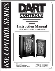
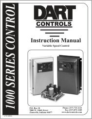
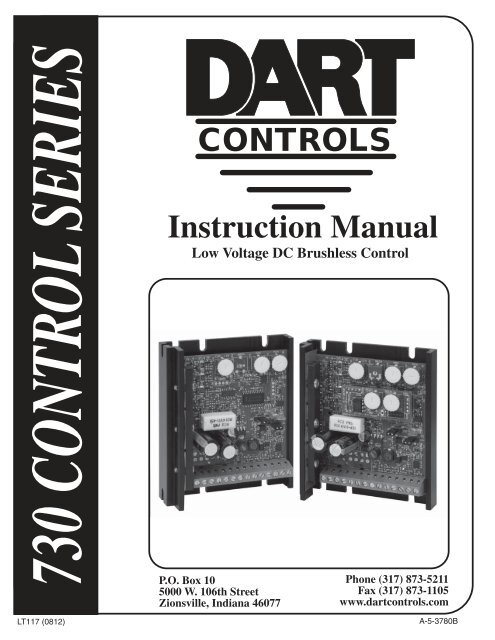
730 CONTROL SERIESCONTROLSInstruction <strong>Manual</strong>Low Voltage DC Brushless ControlP.O. Box 105000 W. 106th StreetZionsville, Indiana 46077Phone (317) 873-5211Fax (317) 873-1105www.dartcontrols.comLT117 (0812)A-5-3780B
TABLE OF CONTENTSWarranty ........................................................................................................................................... 1Warning ............................................................................................................................................. 1Introduction ....................................................................................................................................... 2Standard Features ............................................................................................................................ 2Model Selection ................................................................................................................................ 2Unpacking ......................................................................................................................................... 2Mounting Instructions and Dimensions ......................................................................................... 3Brushless Motor Control Hook-up & Fusing ................................................................................. 3Hook-up Diagram .......................................................................................................................... 4Hook-up Procedure for Motors with Timing Diagrams .................................................................. 4Hook-up Procedure for Motors Without Timing Diagrams ............................................................ 5Features ............................................................................................................................................. 5Sensor Spacing & Input Voltage Selection ................................................................................... 5Speed Command Selection and Hook-up .................................................................................... 6Inhibiting the Control ..................................................................................................................... 6Braking the Control ....................................................................................................................... 6Current Limit / Fault Condition Latch ............................................................................................ 6Motor Direction Selection and Reversing ..................................................................................... 6Power ON LED ............................................................................................................................. 6Internal Fault LED ......................................................................................................................... 6Adjustments ...................................................................................................................................... 7Current Limit ................................................................................................................................. 7Minimum Speed ............................................................................................................................ 7Maximum Speed ........................................................................................................................... 7Closed Loop (731BDC and 733BDC) Gain .................................................................................. 7Accel and Decel (733BDC) ........................................................................................................... 8Heatsink & Cooling ........................................................................................................................... 8Specifications ................................................................................................................................... 8Timing Diagram for 60° Motor ......................................................................................................... 9Timing Diagram for 120° Motor ..................................................................................................... 10Warranty<strong>Dart</strong> <strong>Controls</strong>, Inc. (DCI) warrants its products to be free from defects in material and workmanship. The exclusive remedy forthis warranty is DCI factory replacement of any part or parts of such product which shall within 12 months after delivery to thepurchaser be returned to DCI factory with all transportation charges prepaid and which DCI determines to its satisfaction tobe defective. This warranty shall not extend to defects in assembly by other than DCI or to any article which has been repairedor altered by other than DCI or to any article which DCI determines has been subjected to improper use. DCI assumes noresponsibility for the design characteristics of any unit or its operation in any circuit or assembly. This warranty is in lieu of allother warranties, express or implied; all other liabilities or obligations on the part of DCI, including consequential damages,are hereby expressly excluded.NOTE: Carefully check the control for shipping damage. Report any damage to the carrier immediately. Do not attempt tooperate the drive if visible damage is evident to either the circuit or to the electronic components.All information contained in this manual is intended to be correct, however information and data in this manual are subjectto change without notice. DCI makes no warranty of any kind with regard to this information or data. Further, DCI is notresponsible for any omissions or errors or consequential damage caused by the user of the product. DCI reserves the rightto make manufacturing changes which may not be included in this manual.WarningImproper installation or operation of this control may cause injury to personnel or control failure. The control must beinstalled in accordance with local, state, and national safety codes. Make certain that the power supply is disconnectedbefore attempting to service or remove any components!!! If the power disconnect point is out of sight, lock it indisconnected position and tag to prevent unexpected application of power. Only a qualified electrician or servicepersonnel should perform any electrical troubleshooting or maintenance. At no time should circuit continuity bechecked by shorting terminals with a screwdriver or other metal device.1
Introduction<strong>Dart</strong> <strong>Controls</strong> 730 <strong>Series</strong> is a family of general purpose brushless motor controls. These controlscommutate power into standard 3 phase sensored brushless (BLDC) motors.The 730 <strong>Series</strong> uses DC power sources of 11 to 15VDC or 18 to 54VDC, including batteries of 12,24, 36, and 48 volts. The 730 <strong>Series</strong> will supply up to 7.5 amperes of continuous current to the motorwithout an additional heat sink. With the -HS2 optional heat sink, the 730 series will supply up to 9amperes of continuous current to the motor. It is available in either a basic open loop (<strong>730BDC</strong>), abasic closed loop (731BDC), and a full featured closed loop (733BDC), and all can drive motors withsensor spacings of 60 or 120 degrees.A 14 position terminal strip connects the control to the DC power source, the motor, the speedpot, andthe forward/reverse control switch. A pluggable terminal strip (-P option) is also available. There is a¼” spade pin that can be used for inhibiting the control. There is a 1/8" spade pin that can be used tobrake the control. The control’s PC board carries the minimum speed, maximum speed and currentlimit trimpots for the <strong>730BDC</strong>, an additional gain trimpot for the 731BDC, as well as Accel and Deceltrimpots for the 733BDC.Standard Features● AVAILABLE IN OPEN LOOP (<strong>730BDC</strong>), CLOSED LOOP (731BDC) AND FULLFEATURED (733BDC) VERSIONS● POWER MOSFET TRANSISTORS● QUIET 17KHz “PULSE WIDTH MODULATED” SWITCHED FREQUENCY● FORWARD/REVERSE DIRECTIONAL CONTROL● 5KΩ SPEED POTENTIOMETER W/ DIAL, LEADS & KNOB FOR REMOTE MOUNTING● ANODIZED CHASSIS● INHIBIT INPUT PIN FOR START/STOP OPERATION● BRAKE INPUT PIN FOR QUICK STOP OPERATION● INTERNAL +6.2 VOLT DC SUPPLY FOR MOTOR HALL EFFECT SENSORSModel SelectionMODEL # CONTROL TYPE INPUT VOLTAGE PHASE<strong>730BDC</strong>OPEN LOOP12VDC or 18-54VDCSELECTABLE VIA JUMPER60 o or 120 o SELECTABLEVIA JUMPER731BDCCLOSED LOOP12VDC or 18-54VDCSELECTABLE VIA JUMPER60 o or 120 o SELECTABLEVIA JUMPER733BDCCLOSED LOOP12VDC or 18-54VDCSELECTABLE VIA JUMPER60 o or 120 o SELECTABLEVIA JUMPER733BDC-CLCLOSED LOOP W/CUR LIM LATCH12VDC or 18-54VDCSELECTABLE VIA JUMPER60 o or 120 o SELECTABLEVIA JUMPERUnpackingUnpack the control and check for shipping damage. Locate the motor and its timing diagram. In addition,the 5KΩ speedpot supplied with the chassis control, a DC power source, hook-up wires, and appropriatetools for installation are needed. If the motor does not have a timing diagram, an ammeter of at leasta rating of 200% of the full load motor current and a small hand-held DC volt-ohmmeter are required.2
Mounting Instructions and Dimensions1. Six 3/16" wide slots are provided for control mounting (see dimension diagram below).2. Control chassis can be used as a template.3. Use standard hardware to mount.Caution:Do not mount where ambient temperature is outside range of -10 o C (15 o F) to 45 o C (115 o F).6.000"5.050"4.250".950".188" DIA.(6 SLOTS)P1.694".300"1.750"3.625"0.344"0.750"4.825"5.125".380"1.300".395" .240".315"3.750"1.000"4.840"STANDARD 730 SERIES-HS2Brushless Motor Control Hook-up & FusingBrushless DC motors have eight (8) wires: three (3) phase lines to the motor, three (3) Hall sensorlines, and sensor power and common. Also BLDC motors come in two sensor confi gurations, 60 and120 degrees.Many BLDC motor manufacturers are familiar with the 730 <strong>Series</strong>, and supply specifi c hook-upinformation for the <strong>Dart</strong> control. Other manufacturers only supply timing diagrams, leaving it up to theinstaller to generate a hook-up procedure. Finally, some manufacturers may supply motors with noaccompanying information. The last two situations will be discussed later. All BLDC motors, no matterwhat the hook-up status, are connected to the 730 <strong>Series</strong> control as shown in fi gure 1 of the Hook-UpDiagram section.Notice how the power is connected to terminals P1-4 and P1-5 through an appropriate switch andfuse. <strong>Dart</strong> recommends the use of a Littlefuse 314 <strong>Series</strong> or Bussman ABC <strong>Series</strong> type fuse rated at150% of the full load motor current. The power should be off until the hook-up procedure is completeand the motor is ready to run.3
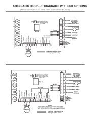
Hook-up DiagramD8Internal Fault LED733BDC-CL ONLYP101P10P2-3 -2 -1P7-3 -2 -1 P3D12Power ON LED-1 -2 -3 -4 -5 -6 -7 -8 -9 -10 -11-12-13-14P1ON/OFFSWITCH+B10/12 AMPNORMALBLOWFUSE-BF/RGND +5VΦ S 1Φ 2S 2Φ 13 S 3BLDCMOTORHI W LOorangeredwhite5KΩSPEEDPOTFigure 1Hook-up Procedure for Motors with Timing DiagramsIt is prudent that when fi rst testing the motor a DC ammeter be placed in series with the DC source.Zero to twenty amperes is fine (an analog movement is preferable).Most manufacturers of BLDC motors send timing diagrams with their product. These diagrams showthe sequencing of the Hall sensor outputs as related to the three motor phases. See pages 9 & 10.The Hall sensor sequencing is very useful, but since everyone has a slightly different way of notatingthe same information, deciphering the motor phases is typically quite confusing. The recommendedprocedure is to hook up the sensors according to their diagrams, then test for the proper motor phases.The current limit circuitry will protect the control from miswired phases.First, determine the spacing of the motor Hall sensors. They will either be 60 or 120 degrees. Usuallythe motor manufacturer will supply the spacing. If they don’t, compare the sensor diagram sent withthe motor with those at the end of this manual. Observe that 60 degree spacing will, at some position,have all sensor lines at logic high. With 120 degree spacing, all three sensors are never at the samelogic level at the same time.Once the spacing is determined, make sure the control is set correctly. Return to the correct wiringdiagram and connect the sensors to terminals S3, S2 and S1 of P1. Notice that for the 60 degreespacing there is a specifi c sensor line that leads the sequence, followed by a line lagging by 60 degrees,and a third line lagging the second by 60 degrees. It is important that the middle line in the train beconnected to terminal S2 of P1.After the sensors are connected, attach the sensor power line to terminal 6.25V of P1. The sensorcommon line is connected to terminal COM of P1. Now attach the three motor armature wires andtest for proper hook-up.It is recommended arbitrarily attaching the phase lines to terminals P1, P2, and P3 of connector P1.Choose a confi guration, test it, and then keep track of the results on paper.4
Now apply power to the control. Slowly increase the speed by adjusting the Speed Pot clockwise.Watch for erratic rotation or excessive source current. If either occurs, immediately turn the Speed Potcounterclockwise to reduce speed, and turn off the power. Try a new phase line confi guration, applypower and test again. There are six (6) different combinations for connecting the three phase lines tothe control. One of them will work. The correct combination will allow smooth rotation of the motor andthe lowest current draw from the DC source.Hook-up Procedure for Motors without Timing DiagramsIf the BLDC motor has with no timing diagram, it is possible, with a little patience, to sort out the variousleads and operate it with the 730 <strong>Series</strong> control. Find a voltmeter that will read a 6.25 volt logic level.First, separate the three motor armature wires from the sensor wires. Armature wires are usually aheavier gauge wire. Once the armature wires are found, check them by measuring the resistancebetween any two. The resistance should be low, under 100 ohms, and be the same across any two ofthe three wires. The remaining fi ve wires are the three sensors, sensor power, and sensor common.To fi nd the power and common, look for color and gauge differences. If all else fails, call the motormanufacturer. Once the sensor power leads have been located, the remaining three leads will be theHall sensors. Now construct a timing diagram using the sensor lines. First, connect the motor to thecontrol, but leave off the three motor armature wires. Don’t worry about sensor spacing at this time.Next, connect the voltmeter to any sensor lead. Reference the meter to terminal COM of P1. Applypower and slowly rotate the motor shaft by hand. The meter should move from 0 to >5 volts as theHall sensor switches. Check the other two sensors for switching.Now, compare each sensor against the others and draw a timing diagram. The motor can now behooked up with this new information using the procedure for motors with timing diagrams.FeaturesSensor Spacing & Input Voltage SelectionNormally the 730 <strong>Series</strong> control is shipped ready for 120 degree sensor spacing (P2-2 and P2-3connected). However, if connecting to a motor that has 60 degree sensor spacing, connect the suppliedjumper to P2-2 to P2-1. Note fi gure 1 of the Hook-Up Diagram section, which shows the location ofthe selectable sensor spacing connector and attached jumper connector. Using this selectable jumperconnector enables the control to drive motors with 60 or 120 degree sensor spacings.The input voltage is also jumper selectable and is shipped with the standard setting of 24/48VDC input(P3-2 and P3-3 connected). If 12 volt input is desired, move the supplied jumper to connect P3-2 toP3-1. See fi gure 1 of the Hook-Up Diagram section for location of the selectable input voltage connectorand attached jumper connector.Speed Command Selection and Hook-upThe 730 series controls can be operated with a 5K potentiometer (supplied with control) or a 0 to 5VDCpower source. The 5K ohm speedpot is connected to terminals P1-12, P1-13, and P1-14. Connect thespeedpot “LO” lead (orange wire) to terminal P1-14, the speedpot “WIPER” lead (red wire) to P1-13,and the speedpot “HI” lead (white wire) to P1-12. A 0 to 5V DC signal can also be used to regulate thespeed. This is accomplished by connecting the DC source signal lead to terminal P1-13 (WIPER) andthe common lead to terminal P1-14 (LO).Note: A 5K ohm resistor must be connected from the Pot Hi terminal (P1-12) to the Pot Lo terminal(P1-14) for proper operation of the Min trimpot.5
Inhibiting the ControlThe 730 series control has a ¼” spade pin (P7) on the control that can be used to inhibit the control.Tying this pin to the control common terminal (P1-6) will stop the control and override any other speedcommand. Using inhibit to start and stop the control will over ride the Accel and Decel settings of the733BDC model. For a start and stop function with Accel and Decel, it is recommended the pot wiperor signal wire, via a switch, be connected to the control wiper input terminal (P1-13) and opened forstop and closed for start.Braking the ControlThe 730B series control has a 1/8” spade pin (P10) on the control that can be used to brake the control.Tying this pin to the control common terminal (P1-6) will quickly stop the control and override any otherspeed command. Using brake to start and stop the control will override the Accel and Decel settingsof the 733BDC model. For a start and stop function with Accel and Decel, it is recommended the potwiper or signal wire, via a switch, be connected to the control wiper input terminal (P1-13) and openedfor stop and closed for start.Current Limit / Fault Condition Latch733BDC-CL OnlyThe 733BDC-CL has a 1/8” spade pin (P101) on the control's top board. If the motor is stalled forany reason, this feature will not allow the motor to restart until the Current Limit Latch feature is reset.Momentarily tying pin (P101) to the control common terminal (P1-6) will reset the Current Limit Latchand override any other speed command. A Fault Condition Latch such as incorrect motor phase ordrive over-temperature will also activate this shutdown / latch feature and may be cleared the sameway (after fault condition is corrected).Motor Direction Selection and ReversingTerminal P1-8 on the 730 <strong>Series</strong> is the forward/reverse control. Allowing terminal P1-8 to remainunconnected will let the motor turn in a particular direction. Connecting terminal P1-8 to P1-6 willreverse the rotation direction. Either a jumper wire, switch, relay, or an open collector NPN transistorcan be used to make this connection. MAKE SURE WHEN THE MOTOR DIRECTION IS REVERSEDTHAT THE MOTOR IS STOPPED. THE CONTROL ISN’T DESIGNED FOR PLUG REVERSING.Sometimes it may be necessary to reverse the motor without using terminal P1-8. This is done bystopping the motor and exchanging terminals P1-1 with P1-2 and terminals P1-10 with P1-11. Thiswill work with either a 60 or 120 degree motor.If the motor draws an excessive amount of current in the reverse direction, this may be a motor designedfor only one direction. Consult with the motor manufacturer about this problem.This completes a general hook-up for the 730 <strong>Series</strong>. The next task is to connect the motor to the control.Power ON LEDThe internal 12V supply has a green LED attached to it for an indication that the internal power supplyis operating and power is applied to the control.Internal Fault LEDThe internal fault LED (Red) indicates that there is a fault condition present with the control. One orseveral of the following fault conditions can be present: invalid sensor input code, 60 o /120 o phasingjumper in wrong direction, over current condition (i.e. Current Limit set too low), undervoltage lockout(i.e. +12V supply is less than 10.0V) or thermal shutdown (i.e. U2 is too hot). Typical fault conditionsare: invalid sensor attachment, 60 o /120 o phasing jumper is in the wrong position, or Current Limit isset too low.6
Current LimitAdjustments<strong>Dart</strong> has factory set the Current Limit to 125% of 7.5 Amps DC. This setting should not need to beincreased. If the current limit needs to be set to a lower value, do so by adjusting the Current Limittrimpot (CL) CCW until the desired setting is achieved.Setting Current LimitCurrent Limit should normally be set to approximately 125% of the FLA rating of the motor that isrunning. To set current limit for the specifi c motor or application, follow these steps while monitoringmotor current:1) Preset Current Limit trimpot (CL) fully CW.2) Run motor at full or normal running speed.3) Load motor to 125% of its FLA rating or the desired maximum load.4) Measure the DC input current with an analog DC current meter placed in series with the PositiveDC input lead.5) Decrease the Current Limit trimpot setting until the motor current begins to drop, and thenslowly increase the setting until just reaching the desired maximum current as obtained in step 3.Note: Do not use the Current Limit trimpot as a torque control or to reduce the speed of a motor.Caution: Remember, keep the average current at 7.5 Amps or under, and make sure the motoris rotating. A stalled motor, after about 30 seconds, may overheat and cause extensive damageto the control and/or motor.Minimum SpeedTurn the speedpot to zero (fully CCW). Next turn the minimum trimpot (MIN) clockwise until the motorbegins to rotate. Slowly rotate the trimpot CCW until the motor stops. The control will now run with azero deadband. If a nonzero minimum speed is desired, rotate the trimpot CW to the desired setting.Maximum SpeedTurn the speedpot fully clockwise. Adjust the maximum trimpot (MAX) counterclockwise to the desiredmaximum output.Closed Loop (731BDC and 733BDC) Gain1. Adjust the Maximum speed trimpot (MAX) to 50% CW rotation.2. Set Closed Loop Gain trimpot to the fully CW position.3. Advance speedpot to the fully CW position. The motor should now be rotating at its maximum speed*.4. Slowly rotate the Closed Loop Gain trimpot CCW until the motor speed decreases slightly**,then rotate the trimpot back CW just enough to return the motor to full speed.5. Refer to the above Minimum Speed (MIN) and Current Limit (CUR LIM) trimpot adjustments.* If the motor doesn’t reach its maximum speed with the speedpot and the gain pot fully CW, rotate theMAX trimpot CW until it does. Proceed with step 4.** If rotating the Closed Loop Gain trimpot fully CCW and the motor speed doesn’t decrease, rotatethe MAX trimpot CCW just enough to make the speed decrease slightly. Then rotate the Closed LoopGain trimpot CW just enough to return the motor to full speed.7
Accel and Decel (733BDC)Accel - The Accel trimpot is adjustable from 0-10 second of maximum output speed setting. The settingof the accel time is approximately proportional to the rotation of the Accel trimpot. As an example, a50% setting of the Accel trimpot will result in approximately a 5 second linear accel ramp from zero tomaximum speed. To test a setting, turn the speedpot to zero (fully CCW). Next turn the Accel trimpotCW to the estimated accel setting. Quickly rotate the speedpot full CW and time the motor accel rampfrom zero to maximum speed. If necessary, adjust the Accel trimpot setting as needed and test again.Decel - The Decel trimpot is adjustable from 0-10 second of maximum output speed setting. Thesetting of the decel time is approximately proportional to the rotation of the Decel trimpot. As anexample, a 50% setting of the Decel trimpot will result in approximately a 5 second linear decel rampfrom maximum to zero speed. To test a setting, turn the speedpot to maximum (fully CW). Next turnthe Decel trimpot CW to the estimated decel setting. Quickly rotate the speedpot full CCW and timethe motor decel ramp from maximum to zero speed. If necessary, adjust the Decel trimpot setting asneeded and test again.Note: Minumum, Maximum and Gain trimpot settings must already be completed to properly set andtest Accel and Decel. Refer to the Open Loop and Closed Loop Trimpot sections above for MinimumSpeed (MIN), Maximum speed (MAX), Current Limit (CUR LIM) and Gain trimpot adjustments.Heatsink & Cooling<strong>Dart</strong> recommends not letting the heatsink temperature rise above 75 o C. (167 o F.). The control, asshipped from the factory, will normally handle up to 7.5 Amps continuous current. With the use ofthe -HS2 optional heat sink, 9.0 Amps continuous current is achievable. If the ambient temperatureincreases above 25 o C. (77 o F.), adding more heatsink or decreasing the current to keep the heatsinktemperature from exceeding 75 o C is a must. Finally, no matter what the heatsink temperature, neverexceed the rated current.SpecificationsINPUT VOLTAGE (JUMPER SELECTABLE) ................................................... 11 to 15VDC OR 18 to 54VDCOUTPUT VOLTAGE ........................................................................................................ 0 to INPUT VOLTAGEMOTOR HALL SPACING - ELECTRICAL (JUMPER SELECTABLE) ......................................... 60 o OR 120 oLOAD CURRENT (CONTINUOUS) .................................................................................................. 7.5 AMPSLOAD CURRENT USING -HS2 (CONTINUOUS) ............................................................................. 9.0 AMPSSPEED RANGE ....................................................................................................................................... 50 : 1MINIMUM SPEED TRIMPOT ......................................................................... ADJUSTABLE 0-30% OF MAX.CURRENT LIMIT TRIMPOT ...................................................................................................... ADJUSTABLEOPEN LOOP SPEED REGULATION ...................................................................... (MODEL <strong>730BDC</strong>) NONEINPUT / OUTPUT CONNECTIONS ........................................................... 14 POSITION TERMINAL BLOCKINPUT / OUTPUT CONNECTIONS USING -P OPTION ....................................... 14 POSITION PLUGGABLESPEED COMMAND SIGNAL ....................... 5K Ohm SPEED POTENTIOMETER or 0 to +5V DC SIGNALOPERATING TEMPERATURE ....................................................................... 0 o C. to 45 o C. (32 o F. to 113 o F.)CLOSED LOOP SPEED REGULATION ............. (MODEL 731BDC and 733BDC) ± 1/2% OF BASE SPEEDMAXIMUM SPEED TRIMPOT ............................................. ADJUSTABLE 60 to 100% OF INPUT VOLTAGEACCELERATION / DECELERATION ...................................... (MODEL <strong>730BDC</strong> and 731BDC) FAST START......................................... (733BDC) ADJUSTABLE 0 – 10 SECONDSINTERNAL VOLTAGE SUPPLY (FOR MOTOR HALL SPACINGS) .................................................. +6.2 VDC8
Timing Diagram for 60° MotorINPUT - 60 o ELECTRICAL MOTORSENSOR 3 (S3) TOTERMINAL P1-11SENSOR 2 (S2) TOTERMINAL P1-10SENSOR 1 (S1) TOTERMINAL P1-9OUTPUT - 60 o ELECTRICAL MOTORPHASE 3 (3) TOTERMINAL P1-1PHASE 2 (2) TOTERMINAL P1-3PHASE 1 (1) TOTERMINAL P1-2Figure 39
Timing Diagram for 120° MotorINPUT - 120 o ELECTRICAL MOTORSENSOR 1 (S1) TOTERMINAL P1-9SENSOR 2 (S2) TOTERMINAL P1-10SENSOR 3 (S3) TOTERMINAL P1-11OUTPUT - 120 o ELECTRICAL MOTORPHASE 1 (θ1) TOTERMINAL P1-2PHASE 2 (θ2) TOTERMINAL P1-3PHASE 3 (θ3) TOTERMINAL P1-1Figure 410
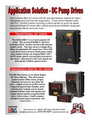
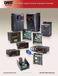
REPAIR PROCEDUREIn the event that a Product manufactured by <strong>Dart</strong> <strong>Controls</strong> Incorporated (DCI) is in need of repairservice, it should be shipped, freight paid, to: <strong>Dart</strong> <strong>Controls</strong>, Inc., 5000 W. 106th Street, Zionsville,IN. 46077, ATTN: Repair Department. Please include Name, Shipping Address (no P.O. Box),Phone Number and if possible, e-mail address.Those orders received from anyone without an existing account with DCI must specify if they willbe paying COD or Credit Card (Master Card/Visa/American Express). This information is requiredbefore work will begin. If you have an account with <strong>Dart</strong> your order will be processed accordingto the terms listed on your account. Products with Serial Number date codes over 5 years oldwill automatically be deemed Beyond Economical Repair (BER). A new, equivalent device will beoffered at a substantial discount.Completed repairs are returned with a Repair Report that states the problem with the controland the possible cause. Repair orders are returned via UPS Ground unless other arrangementsare made. If you have further questions regarding repair procedures, contact <strong>Dart</strong> <strong>Controls</strong>, Inc.at 317-873-5211.YOUR MOTOR SPEED CONTROL SOLUTIONS PROVIDER125D SERIESAC INPUT - VARIABLE DC OUTPUT1/50 HP through 1.0 HP250G SERIESAC INPUT - VARIABLE DC OUTPUT1/50 HP through 2.0 HP65 SERIESDC INPUT - VARIABLE DC OUTPUTCURRENT RATINGS OF 20, 40, AND60 AMPS700/COMMUTROL SERIESDC BRUSHLESS5 & 20 Amp for12,24,& 36VDC Inputs<strong>Dart</strong> <strong>Controls</strong>, Inc. is adesigner, manufacturer, andmarketer of analog anddigital electronic variablespeed drives, controls, andaccessories for AC, DC,and DC brushless motorapplications.Shown above is just a samplingof the expanded line of <strong>Dart</strong>controls that feature the latestin electronic technology andengineering. Products aremanufactured in the U.S.A. atour Zionsville (Indianapolis,MDP SERIESPROGRAMMABLECLOSED LOOP DCSPEED CONTROLIndiana) production andheadquarters facility - with over2,000,000 variable speed unitsin the fi eld.In addition to the standardoff-the-shelf products, you canselect from a wide variety ofoptions to customize controlsfor your specifi c application.For further information andapplication assistance,contact your local <strong>Dart</strong> salesrepresentative, stockingdistributor, or <strong>Dart</strong> <strong>Controls</strong>,Inc.www.dartcontrols.comISO9001:2008 REGISTEREDDM SERIESFIELD PROGRAMMABLEDIGITAL TACHOMETER<strong>Dart</strong> <strong>Controls</strong>, Inc.Manufacturer of high qualityDC and AC motor speedcontrols and accessoriessince 1963.P.O. Box 105000 W. 106th StreetZionsville, Indiana 46077Phone: (317) 873-5211Fax: (317) 873-1105