battery charger - Vanner
battery charger - Vanner
battery charger - Vanner

Create successful ePaper yourself
Turn your PDF publications into a flip-book with our unique Google optimized e-Paper software.
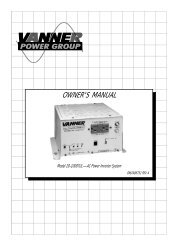
VANNER Incorporated<br />
Owners Manual<br />
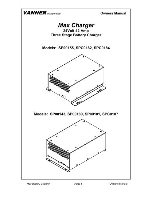
Max Charger<br />
24Volt 42 Amp<br />
Three Stage Battery Charger<br />
Models: SP00155, SPC0182, SPC0184<br />
Models: SP00143, SP00180, SP00181, SPC0187<br />
Max Battery Charger Page 1 Owner’s Manual
VANNER Incorporated<br />
Owners Manual<br />
Table of Contents<br />
1 Introduction .................................................................................................... 3<br />
2 General Information ...................................................................................... 3<br />
2.1 Introduction and Checkout ................................................................. 3<br />
2.2 Specifications ..................................................................................... 4<br />
2.3 Standard Features ............................................................................. 4<br />
3 Installation and Checkout ............................................................................. 5<br />
3.1 Selection of Battery Charger Location ................................................ 7<br />
3.2 Charger Mounting .............................................................................. 8<br />
3.3 Routing and Connecting Battery Charger DC Output Cables............. 8<br />
4 Battery Charger Operating Procedure ......................................................... 9<br />
4.1 Charger Setup .................................................................................... 9<br />
4.2 Charging Stages ................................................................................ 9<br />
5 Operation LED ............................................................................................. 10<br />
5.1 LED Status ....................................................................................... 10<br />
Figures<br />
F 1 Figure 2.1-1 <strong>Vanner</strong> Max Illustration ......................................................................................... 3<br />
F 2 Figure 3.4-1 Max Battery Charger Wiring Diagram ................................................................... 8<br />
F 3 Figure 4.2-1 Max Three-Stage Battery Charging Graph ........................................................... 9<br />
Max Battery Charger Page 2 Owner’s Manual
VANNER Incorporated<br />
Owners Manual<br />
Introduction<br />
Thank you for purchasing the <strong>Vanner</strong> Max Battery Charger. We are confident that you will be<br />
satisfied with this <strong>charger</strong>'s performance and its many features. With proper installation and care,<br />
you can look forward to years of service from this high performance product.<br />
This document will describe the operation, technical specifications, and installation procedures of<br />
this product. If you require additional information please contact your dealer, or contact <strong>Vanner</strong><br />
directly at the phone number or email address shown on the back of this manual.<br />
1 General Information<br />
1.1 Introduction<br />
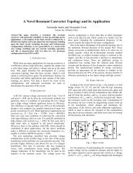
The <strong>Vanner</strong> Max Battery Charger is a high performance three-stage <strong>battery</strong> <strong>charger</strong> that has the<br />
ability to precisely charge 24VDC <strong>battery</strong> banks. The Max incorporates advanced <strong>battery</strong><br />
charging technology, correctly charging batteries automatically at the <strong>charger</strong>’s rated ampere<br />
output rather than tapering off like some other <strong>battery</strong> <strong>charger</strong>s. This three-stage design keeps<br />
batteries in top condition and minimizes <strong>battery</strong> failure, resulting in maximum <strong>battery</strong> life.<br />
FAN<br />
FLOAT<br />
GREEN<br />
BULK<br />
AMBER<br />
OVERTEMP<br />
RED<br />
F 1 Figure 2.1-1 <strong>Vanner</strong> Max Illustration<br />
Max Battery Charger Page 3 Owner’s Manual
VANNER Incorporated<br />
Owners Manual<br />
1.2 Specifications<br />
Model Numbers<br />
SP00143, SP00180,<br />
SP00181<br />
SP00155 SPC0184 SPC0182 SPC0187<br />
Input 15A at 120VAC ±10%, 60Hz ±10%<br />
Output<br />
DC Current Draw with<br />
no AC voltage applied<br />
“AC is connected”<br />
Output Signal, 4A max<br />
42A at 24VDC Nominal, 4AWG cables<br />
30 milliamps None<br />
30<br />
milliamps<br />
Ground (B-) +24VDC (B+) Ground (B-)<br />
Bulk Voltage (Nominal) 28.6VDC 29.8VDC<br />
Absorption Time<br />
20 Minutes<br />
Float Voltage (Nominal) 26.6VDC 27.4VDC<br />
Ambient Temperature<br />
Cooling<br />
Chassis<br />
Weight<br />
Dimensions<br />
-40 to +105°F (-40 to +40°C)<br />
Forced Air, 100 CFM, 24VDC Fan with front to rear air flow<br />
Steel with durable painted finish<br />
35 lbs<br />
9.85" W x 6.70" H x 15.75" D<br />
1.3 Standard Features<br />
• Fully automatic operation with three-stage <strong>battery</strong> charging (Bulk, Absorption, and Float)<br />
• Over current protection of AC input and DC output to protect both the <strong>charger</strong> and the<br />
batteries<br />
• Durable steel enclosure<br />
• 3 Status LED’s indicating: charging status (green and yellow), over temperature fault (red),<br />
and wiring disconnected (blinking green).<br />
• Output signal to indicate that the <strong>charger</strong> is connected to 120VAC.<br />
Max Battery Charger Page 4 Owner’s Manual
VANNER Incorporated<br />
Owners Manual<br />
2 Installation Instructions<br />
These symbols are used to note procedures that if not closely followed could lead to loss of life or<br />
damage to equipment or property due to electrocution.<br />
Electrocution hazard exists<br />
Fire hazard exists<br />
A potentially dangerous condition<br />
Explosive hazard exists<br />
Corrosive hazard exists<br />
Fault protection devices must be installed between the <strong>charger</strong> and<br />
the <strong>battery</strong>. A fault protection device would be any fuse or circuit breaker properly rated for the<br />
maximum DC current obtainable. This advisory is in accordance with SAE, NEC and UL, for<br />
mobile power applications. Install per applicable codes or within 18” of the <strong>battery</strong>. Contact<br />
<strong>Vanner</strong> at 1-800-227-6937 or pwrsales@vanner.com if assistance is needed in sizing fault<br />
protection devices.<br />
Caution: This equipment tends to produce arcs and sparks during<br />
installation. To prevent fire or explosion, compartments containing batteries or flammable<br />
materials must be properly ventilated. Safety goggles should always be worn when working near<br />
batteries<br />
WARNING: Before installing and using the MAX Charger, be sure to read<br />
and save these safety instructions.<br />
This manual contains important safety and operating instructions for the <strong>Vanner</strong> MAX Battery<br />
Charger<br />
CAUTION:<br />
CAUTION:<br />
WARNING:<br />
WARNING:<br />
Warning:<br />
Read owners manual BEFORE wiring or powering up.<br />
DO NOT cover or obstruct ventilation openings. DO NOT mount in a zeroclearance<br />
compartment. Overheating may result.<br />
Under high ambient temperature / high-power-output conditions some parts of<br />
the <strong>charger</strong> may become hot enough to cause burns. The unit should be installed<br />
so that it is not to be contacted by personnel.<br />
Improper use of this product may result in risk of electrical shock. Both AC and<br />
DC voltage sources are terminated inside this equipment.<br />
Battery connections are for disconnect only, NOT for current interruption.<br />
Max Battery Charger Page 5 Owner’s Manual
VANNER Incorporated<br />
Owners Manual<br />
2.1 General Precautions<br />
Do not expose the <strong>charger</strong> to direct water spray or snow.<br />
To reduce the risk of a fire hazard, do not cover or obstruct the ventilation openings.<br />
Do not install the <strong>charger</strong> in a zero clearance compartment. This may result in<br />
overheating or diminished performance.<br />
To avoid the risk of fire, electrical shock, or injury to persons, do not use<br />
attachments not recommended or sold by the <strong>Vanner</strong> Inc.<br />
<strong>Vanner</strong> recommends that all AC and DC electrical wiring be performed by a licensed<br />
electrician or a qualified technician to ensure compliance with all applicable national and local<br />
wiring regulations.<br />
To avoid a risk of fire and/or electrical shock, always verify wiring<br />
connections are in good electrical condition. All external conductors must use proper wire<br />
size to avoid dangerous overheating or diminished performance.<br />
If the <strong>charger</strong> has been dropped or damaged in any way, do not operate the <strong>charger</strong><br />
until it has been verified to be safe by a qualified technician.<br />
To reduce the risk of electrical shock, always disconnect the AC and DC connections<br />
to the <strong>charger</strong> before attempting any maintenance. Simply turning the <strong>charger</strong> off does not<br />
prevent electrical shock.<br />
The <strong>charger</strong> must be properly grounded in accordance with local and national codes<br />
and ordinances before operation. For most installations, the negative (ground) conductor<br />
should be bonded to the grounding system at one and only one point in the system.<br />
For optimum <strong>charger</strong> performance, <strong>battery</strong> temperature should be above 32 degrees<br />
Fahrenheit.<br />
Do not disassemble the <strong>charger</strong>. See the service section of this manual for<br />
instructions on obtaining service. Attempting to service the inverter yourself may result in a<br />
risk of electrical shock, fire and/or loss of warranty.<br />
Max Battery Charger Page 6 Owner’s Manual
VANNER Incorporated<br />
Owners Manual<br />
To reduce the risk of <strong>battery</strong> explosion, follow these instructions, the <strong>battery</strong><br />
manufacturer instructions, and the instructions of the manufacturer of the equipment in which<br />
the <strong>battery</strong> is installed. Working near a lead-acid <strong>battery</strong> is dangerous. Batteries generate<br />
explosive gases during normal <strong>battery</strong> operation.<br />
2.2 Battery Precautions<br />
1. Always have someone within range of your voice to come to your aid when you work near a<br />
lead-acid <strong>battery</strong>.<br />
2. Have close access to plenty of fresh water and soap in case <strong>battery</strong> acid contacts skin,<br />
clothing, or eyes.<br />
3. Always wear complete eye protection and clothing protection. Avoid touching eyes while<br />
working near batteries.<br />
4. If <strong>battery</strong> acid contacts skin or clothing, wash immediately with soap and water. If acid enters<br />
eye, immediately flood eye with running cold water for at least 20 minutes. Get medical<br />
attention immediately.<br />
5. NEVER smoke or allow a spark or flame near a <strong>battery</strong>. Gases produced by batteries are<br />
explosive.<br />
6. Be careful when working with metal tools around batteries. Potentials exist for sparks or<br />
short-circuit of the <strong>battery</strong> or other electrical part which could cause an explosion.<br />
3 Installation and Checkout<br />
3.1 Selection of Battery Charger Location<br />
NOTE<br />
Charger should not<br />
be installed in same<br />
compartment as batteries<br />
where corrosive or explosive<br />
gases are present.<br />
• Charger should be located close to <strong>battery</strong>. Locate within 3’ for<br />
optimum performance, but not in the same compartment.<br />
• Charger should be protected from weather. Install in a location<br />
that provides protection from direct water spray and dirt.<br />
• Mounting compartment should be well-ventilated and allow<br />
adequate air circulation for <strong>charger</strong> cooling. Allow 2" clearance<br />
around entire <strong>charger</strong>.<br />
• Do not store flammable items near <strong>charger</strong>. Do not expose<br />
<strong>charger</strong> to corrosive or explosive vapors.<br />
Max Battery Charger Page 7 Owner’s Manual
VANNER Incorporated<br />
Owners Manual<br />
3.2 Charger Mounting<br />
• Install the MAX Charger in the horizontal upright position. The <strong>charger</strong> is furnished with<br />
mounting brackets which provide adequate clearance for under chassis airflow. The <strong>charger</strong><br />
requires under chassis airflow for proper cooling.<br />
3.3 Routing and Connecting Battery Charger Output Cables<br />
This Charger is designed for 24 VDC applications only. If<br />
connected to other than 24V system, damage will result.<br />
WARNING<br />
Safety goggles<br />
should be worn<br />
when working with<br />
or near batteries<br />
WARNING<br />
Battery connections<br />
must be able to carry a<br />
minimum of 50 amps.<br />
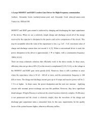
1. Connect the Max Charger's RED cable to the <strong>battery</strong>'s<br />
positive (+) terminal and the BLACK cable to the<br />
Battery's negative (-) terminal.<br />
2. Install a fuse in line with the positive <strong>battery</strong> source to<br />
the <strong>charger</strong>. Size fuse at an 80Amp minimum to a 150A<br />
maximum.<br />
3. Battery cable connections must be clean and secure to<br />
minimize electrical resistance for optimum performance.<br />
4. Route and secure <strong>charger</strong> DC cables away from Hot and<br />
Sharp surfaces and components.<br />
5. “AC power is Present” mating connection is a<br />
Delphi Weather-Pack 12015791 with terminal selected<br />
per the gauge wire required for application.<br />
MAX Charger<br />
12 Volt<br />
+<br />
Battery<br />
-<br />
12 Volt<br />
+<br />
Battery<br />
-<br />
Output Signal notifying<br />
that AC power is Present<br />
F 2 Figure 3.4-1 Max Battery Charger Wiring Diagram<br />
Max Battery Charger Page 8 Owner’s Manual
VANNER Incorporated<br />
Owners Manual<br />
4 Battery Charger Operation<br />
4.1 Charger ON/OFF Control<br />
1. There is no ON/OFF switch. Turn the <strong>charger</strong> ON by connecting the AC input line cord<br />
to a 15 Amp 120 Volt 60Hz power source. Turn the <strong>charger</strong> OFF by disconnecting AC<br />
power.<br />
2. The <strong>charger</strong> will not accept AC power above 65Hz or voltage below approx 100 VAC.<br />
4.2 Description of the Three Battery Charging Stages<br />
1. Charging begins when the unit receives 120VAC shore power. In Bulk Stage the<br />
<strong>charger</strong> output amps will be at full rated output and <strong>battery</strong> voltage will rise until <strong>battery</strong><br />
voltage reaches the models specified voltage. Battery voltage is held by reducing<br />
output current as needed. Bulk Stage ends when <strong>charger</strong> output current is reduced to<br />
75% of rated output. The <strong>charger</strong> then shifts to Absorption Stage.<br />
2. Absorption Stage holds <strong>battery</strong> voltage at the stated bulk rate for 20 minutes. Charger<br />
output current will vary as needed to hold <strong>battery</strong> voltage constant. After 20 minutes<br />
Absorption Stage ends and Float Stage begins.<br />
3. Float Stage holds the <strong>battery</strong> voltage at models specified voltage. Charger output<br />
current will vary as needed to hold <strong>battery</strong> voltage constant. Float Stage ends when<br />
<strong>charger</strong> output amps reaches full rated output. (In a normal situation the <strong>charger</strong> will<br />
cycle to Float Stage one time and then remain in Float Stage until disconnected from<br />
AC power. Please note: DC LOADS may cause the <strong>charger</strong> to reach full output<br />
which will cause Bulk Stage to restart. The batteries may be damaged due to<br />
overcharging if DC LOADS cause Bulk Stage to restart repeatedly.)<br />
30<br />
100<br />
Bulk Mode<br />
Absorption Mode for 20 minutes<br />
90<br />
25<br />
75% Rated Current<br />
Float Mode<br />
80<br />
Battery Voltage<br />
20<br />
15<br />
10<br />
70<br />
60<br />
50<br />
40<br />
30<br />
5<br />
20<br />
10<br />
0<br />
0 2.5 5 7.5 10 12.5 15 17.5 20 22.5 25 27.5 30 32.5 35 37.5 40<br />
0<br />
Time in Minutes<br />
- - - % Rated Charging Amps<br />
── Battery Voltage<br />
F 3 Figure 4.2-1 <strong>Vanner</strong> Max Three-Stage Battery Charging Graph<br />
Max Battery Charger Page 9 Owner’s Manual
VANNER Incorporated<br />
Owners Manual<br />
5 Operation<br />
LED Status Indicators for Models SP00143, SP00180, SP00181 and SPC0187<br />
LED<br />
Yellow solid<br />
Green solid<br />
Red solid<br />
Green<br />
BLINKING<br />
No LED’s<br />
Charger Status<br />
The <strong>charger</strong> is ON and is in Bulk Stage or Absorption Stage.<br />
The <strong>charger</strong> is ON and is in Float Stage.<br />
The <strong>charger</strong> is OFF because internal temperature is too high. Shutdown may<br />
have been caused by high ambient temperature or by restricted cooling air flow.<br />
The <strong>charger</strong> will automatically restart when internal temperature is acceptable.<br />
The <strong>charger</strong> is OFF. Either 120VAC is disconnected or <strong>battery</strong> is disconnected.<br />
The <strong>charger</strong> is OFF and is disconnected from both 120VAC and <strong>battery</strong>.<br />
LED Status Indicators for Models SP00155, SPC0182 and SPC0184<br />
LED<br />
Yellow solid<br />
Green solid<br />
Red solid<br />
Green<br />
Blinking<br />
No LED’s<br />
Charger Status<br />
The <strong>charger</strong> is ON and is in Bulk Stage or Absorption Stage.<br />
The <strong>charger</strong> is ON and is in Float Stage.<br />
The <strong>charger</strong> is OFF because internal temperature is too high. Shutdown may<br />
have been caused by high ambient temperature or by restricted cooling air flow.<br />
The <strong>charger</strong> will automatically restart when internal temperature is acceptable.<br />
The <strong>charger</strong> is OFF. The <strong>charger</strong> is connected to 120VAC but is disconnected<br />
from <strong>battery</strong>.<br />
The <strong>charger</strong> is OFF because 120VAC is disconnected. (Battery connection<br />
status is not defined.)<br />
Max Battery Charger Page 10 Owner’s Manual
VANNER Incorporated<br />
Owners Manual<br />
Notes:<br />
Max Battery Charger Page 11 Owner’s Manual
VANNER Incorporated<br />
Owners Manual<br />
<strong>Vanner</strong> Incorporated<br />
4282 Reynolds Drive<br />
Hilliard, Ohio 43026<br />
1-800-AC POWER<br />
(1-800-227-6937)<br />
Tel: 614-771-2718<br />
Fax: 614-771-4904<br />
www.vanner.com<br />
e-mail: pwrsales@vanner.com<br />
Manual Number D97598-F<br />
January 28, 2013<br />
Max Battery Charger Page 12 Owner’s Manual