Directed Reading Continuing Education Quiz - American Society of ...
Directed Reading Continuing Education Quiz - American Society of ...
Directed Reading Continuing Education Quiz - American Society of ...

You also want an ePaper? Increase the reach of your titles
YUMPU automatically turns print PDFs into web optimized ePapers that Google loves.
RADIOLOGIC<br />
Journal <strong>of</strong> the <strong>American</strong> <strong>Society</strong> <strong>of</strong> Radiologic Technologists Vol. 81, No. 5 May/June 2010<br />
Radiation Dose in Computed Tomography<br />
Diagnosis and Treatment <strong>of</strong> Ankle Fractures<br />
Computed Tomography Shielding Methods: A Literature Review<br />
R.T.s With Doctorates: Barriers To Conducting Research<br />
®<br />
<strong>American</strong> <strong>Society</strong> <strong>of</strong><br />
Radiologic Technologists
Everyone talks about<br />
lowering healthcare costs.<br />
We’re done talking.<br />
Lowering Costs Patient Safety Medical Accuracy Training Treatment<br />
At Covidien, we know one <strong>of</strong> the most complex procedures<br />
in modern healthcare is managing its financial impact.<br />
That’s why all <strong>of</strong> our technologies and initiatives are geared<br />
toward heightening safety measures, reducing complications<br />
and even shortening hospital stays in order to improve patient<br />
outcomes and reduce costs. To learn more about how we’re<br />
improving the health <strong>of</strong> patients and bottom lines alike,<br />
visit us at covidien.com/successstories.<br />
© 2009 Covidien. COVIDIEN, COVIDIEN with Logo, the Covidien Logo and “positive results for life” are U.S. and/or internationally registered trademarks <strong>of</strong> Covidien AG.
Get More<br />
From Your ASRT<br />
Membership!<br />
Select Your<br />
Area <strong>of</strong> Interest.<br />
CE opportunities to<br />
suit your needs.<br />
Can be an area other<br />
than your primary<br />
sphere <strong>of</strong> practice.<br />
Edit your member<br />
information at<br />
www.asrt.org<br />
or call 800-444-2778, Press 5.<br />
©2007 ASRT. All rights reserved.
A wide new window <strong>of</strong> opportunity 1,2<br />
Introducing ABLAVAR : the first and only blood-pool contrast agent for MRA 1,2<br />
A low-dose MRA contrast agent with the unique benefits <strong>of</strong> albumin binding 3<br />
• Time to acquire high-resolution first-pass and steady-state images 3<br />
• Imaging window up to 1 hour with a single, low-dose (0.12 mL/kg body weight<br />
[0.03 mmol/kg]) IV bolus 1,3<br />
• Diagnostic accuracy comparable to conventional X-ray angiography 4,5<br />
• Documented safety and tolerability with no reported cases <strong>of</strong> NSF* 6<br />
*No reported cases <strong>of</strong> nephrogenic systemic fibrosis (NSF) to date in clinical use with nearly 90,000 patients outside <strong>of</strong> the United States.<br />
References: 1. ABLAVAR [package insert]. North Billerica, MA: Lantheus Medical Imaging, Inc.; 2009. 2. U.S. Food and Drug Administration Web site. http://www.fda.gov/<br />
drugs. Accessed February 1, 2010. 3. Goyen M. Gad<strong>of</strong>osveset-enhanced magnetic resonance angiography. Vasc Health Risk Manag. 2008;4(1):1-9. 4. Goyen M, Edelman<br />
M, Perreault P, et al. MR angiography <strong>of</strong> aortoiliac occlusive disease: a phase III study <strong>of</strong> the safety and effectiveness <strong>of</strong> the blood-pool contrast agent MS-325. Radiology.<br />
2005;236(3):825-833. 5. Rapp JH, Wolff SD, Quinn SF, et al. Aortoiliac occlusive disease in patients with known or suspected peripheral vascular disease: safety and effi cacy<br />
<strong>of</strong> gad<strong>of</strong>osveset-enhanced MR angiography–multicenter comparative phase III study. Radiology. 2005;236(1);71-78. 6. Data on fi le, Lantheus Medical Imaging, Inc.
INDICATIONS: ABLAVAR is indicated for use as a contrast<br />
agent in magnetic resonance angiography (MRA) to evaluate<br />
aortoiliac occlusive disease (AIOD) in adults with known or<br />
suspected peripheral vascular disease.<br />
CONTRAINDICATIONS: History <strong>of</strong> a prior allergic<br />
reaction to a gadolinium-based contrast agent.<br />
IMPORTANT SAFETY INFORMATION:<br />
WARNING: NEPHROGENIC SYSTEMIC FIBROSIS<br />
(NSF) Gadolinium-based contrast agents<br />
increase the risk <strong>of</strong> nephrogenic systemic<br />
fibrosis (NSF) in patients with:<br />
• acute or chronic severe renal insufficiency<br />
(glomerular filtration rate
412 May/June 2010, Vol. 81/No. 5 RADIOLOGIC TECHNOLOGY
An Official Journal<br />
Radiologic Technology (ISSN 0033-8397) is the<br />
<strong>of</strong>ficial scholarly/pr<strong>of</strong>essional journal <strong>of</strong> the<br />
<strong>American</strong> <strong>Society</strong> <strong>of</strong> Radiologic Technologists. It<br />
is published bimonthly at 15000 Central Ave SE,<br />
Albuquerque, NM 87123-3909. Months <strong>of</strong> issue are<br />
January/February, March/April, May/June, July/<br />
August, September/October and November/December.<br />
Periodical class postage paid at Albuquerque,<br />
NM, and at additional mailing <strong>of</strong>fices. Printed<br />
in the United States. ©2010 <strong>American</strong> <strong>Society</strong> <strong>of</strong><br />
Radiologic Technologists.<br />
The research and information in Radiologic<br />
Technology are generally accepted as factual at<br />
the time <strong>of</strong> publication. However, the ASRT and<br />
authors disclaim responsibility for any new or<br />
contradictory data that may become available after<br />
publication. Opinions expressed in the Journal are<br />
those <strong>of</strong> the authors and do not necessarily reflect<br />
the views or policies <strong>of</strong> the ASRT.<br />
Postmaster<br />
Postmaster: Send change <strong>of</strong> address to<br />
Radiologic Technology, c/o the <strong>American</strong> <strong>Society</strong> <strong>of</strong><br />
Radiologic Technologists, 15000 Central Ave SE,<br />
Albuquerque, NM 87123-3909.<br />
Editorial<br />
Radiologic Technology is a peer-reviewed journal<br />
produced by the <strong>American</strong> <strong>Society</strong> <strong>of</strong> Radiologic<br />
Technologists for the benefit and advancement <strong>of</strong><br />
all technological disciplines within medical imaging<br />
and radiation therapy. Editorial correspondence<br />
should be addressed to Radiologic Technology Editor,<br />
15000 Central Ave SE, Albuquerque, NM 87123-<br />
3909. Phone 505-298-4500, 8 a.m. to 4:30 p.m.<br />
Mountain time; e-mail communications@asrt.org.<br />
Letters <strong>of</strong> inquiry prior to finished manuscript<br />
production are encouraged and frequently will be<br />
reviewed by both the editor and the chairman <strong>of</strong> the<br />
Editorial Review Board.<br />
The initials “R.T.” following proper names in<br />
this journal refer to individuals certified by the<br />
<strong>American</strong> Registry <strong>of</strong> Radiologic Technologists.<br />
Subscriptions, Change <strong>of</strong> Address<br />
ASRT member change <strong>of</strong> address: Address<br />
correspondence to the <strong>American</strong> <strong>Society</strong> <strong>of</strong><br />
Radiologic Technologists, Attention: Member<br />
Services, 15000 Central Ave SE, Albuquerque, NM<br />
87123-3909. Call the ASRT <strong>of</strong>fice from 8 a.m. to<br />
4:30 p.m. Mountain time at 800-444-2778; fax 505-<br />
298-5063. ASRT members also can submit changes<br />
<strong>of</strong> address online at www.asrt.org.<br />
Nonmember subscriber change <strong>of</strong> address:<br />
Send an old mailing label and the new address,<br />
including ZIP code, at least 6 weeks in advance<br />
to ASRT, Attention: Member Services, 15000<br />
Central Ave SE, Albuquerque, NM 87123-3909.<br />
Claims are not allowed for issues lost as a result<br />
<strong>of</strong> insufficient notice <strong>of</strong> change <strong>of</strong> address. The<br />
publisher cannot accept responsibility for undelivered<br />
copies.<br />
Subscription rates and order processing:<br />
Member subscription is $7.03 per year, included<br />
in ASRT member dues. Nonmember subscription<br />
<strong>of</strong> one volume <strong>of</strong> 6 issues is $70 within the United<br />
States for individuals; foreign, $105, including<br />
Canada. Institutional rates also are available. Discounted<br />
rates apply to 2- and 3-year subscriptions<br />
and subscription agencies. Single issues, both current<br />
and back, exist in limited quantities and are<br />
<strong>of</strong>fered for sale. For prices and availability, phone<br />
ASRT Member Services at 800-444-2778. Journal<br />
orders must be paid in advance by check, money<br />
order or credit card drawn on a U.S. bank in U.S.<br />
funds only. Send payment to ASRT, PO Box 27447,<br />
Albuquerque, NM 87125-7447. Prices are subject<br />
to change.<br />
Advertising<br />
All commercial display advertising and classified<br />
advertising is handled by the ASRT Corporate Relations<br />
Department, 15000 Central Ave SE, Albuquerque,<br />
NM 87123-3909. For information on rates and<br />
deadlines, contact JoAnne Quirindongo at 800-444-<br />
2778, Ext. 1317, or e-mail jquirindongo@asrt.org.<br />
Radiologic Technology reserves the right to reject<br />
or revise any advertising copy that it considers<br />
objectionable, either because said copy is not<br />
consistent with usual pr<strong>of</strong>essional standards <strong>of</strong><br />
propriety or for any other reason deemed material.<br />
In any event, the advertiser assumes full liability for<br />
the content <strong>of</strong> all advertising copy printed.<br />
All advertising materials submitted become<br />
the property <strong>of</strong> ASRT. Advertisements submitted<br />
beyond the deadline for pro<strong>of</strong> service are done so<br />
at the advertiser’s risk. Publication <strong>of</strong> an advertisement<br />
in Radiologic Technology does not imply endorsement<br />
<strong>of</strong> its claims by the editor or publisher.<br />
For advertising specifically related to educational<br />
programs, ASRT does not guarantee, warrant,<br />
claim or in any way express an opinion relative to<br />
the accreditation status <strong>of</strong> said program.<br />
Rights Reserved<br />
All articles, illustrations and other materials<br />
carried herein are pending copyright under U.S.<br />
copyright laws, and all rights thereto are reserved by<br />
the publisher, the <strong>American</strong> <strong>Society</strong> <strong>of</strong> Radiologic<br />
Technologists. Any and all copying or reproduction<br />
<strong>of</strong> the contents herein for general distribution, for<br />
advertising or promotion, for creating new collective<br />
works or for resale is expressly forbidden without<br />
prior written approval by the publisher and, in some<br />
cases, the authors.<br />
Copying for personal use only through application<br />
and payment <strong>of</strong> a per-copy fee as required<br />
by the Copyright Clearance Center Inc, under<br />
permission <strong>of</strong> Sections 107 and 108 <strong>of</strong> the U.S.<br />
copyright laws. Violators will be prosecuted.<br />
Member <strong>of</strong><br />
BPA International<br />
RADIOLOGIC TECHNOLOGY May/June 2010, Vol. 81/No. 5<br />
413
Radiologic<br />
Technology<br />
Editorial<br />
Review Board<br />
Chairman<br />
Laura Carwile Aaron, PhD, R.T.(R)(M)(QM)<br />
Northwestern State University<br />
Shreveport, Louisiana<br />
Vice Chairman<br />
Nina K Kowalczyk, PhD, R.T.(R)(CT)(QM), FASRT<br />
The Ohio State University<br />
Columbus, Ohio<br />
Members<br />
Sarah S Baker, EdD, R.T.(R), FASRT<br />
Indiana University School <strong>of</strong> Medicine<br />
Indianapolis, Indiana<br />
Melissa B Jackowski, EdD, R.T.(R)(M)<br />
University <strong>of</strong> North Carolina<br />
Chapel Hill, North Carolina<br />
James Johnston, PhD, R.T.(R)(CV)<br />
Midwestern State University<br />
Wichita Falls, Texas<br />
James Kilmartin, R.T.(R), FACHE, FAHRA<br />
Stormont-Vail HealthCare<br />
Topeka, Kansas<br />
Jeffrey S Legg, PhD, R.T.(R)(CT)(QM)<br />
Virginia Commonwealth University<br />
Richmond, Virginia<br />
Tricia Leggett, DHEd, R.T.(R)(QM)<br />
Zane State College<br />
Zanesville, Ohio<br />
Michael E Madden, PhD, R.T.(R)(CT)(MR)<br />
Fort Hays State University<br />
Hays, Kansas<br />
Kimberly Metcalf, EdD, R.T.(R)(T)<br />
Massachusetts General Hospital<br />
Institute <strong>of</strong> Health Pr<strong>of</strong>essions<br />
Boston, Massachusetts<br />
Bette Schans, PhD, R.T.(R), FASRT<br />
Mesa State College<br />
Grand Junction, Colorado<br />
Diane Scutt, PhD<br />
University <strong>of</strong> Liverpool<br />
Liverpool, United Kingdom<br />
Bettye G Wilson, MEd, R.T.(R)(CT),<br />
RDMS, FASRT<br />
University <strong>of</strong> Alabama at Birmingham<br />
Birmingham, Alabama<br />
ASRT Journal Staff<br />
Kathryn Faguy, ELS, publications manager<br />
Ellen Lipman, director <strong>of</strong> pr<strong>of</strong>essional development<br />
Julie James-Griego, art director<br />
Michelle Stephens, associate editor<br />
Marge Montreuil, graphic designer<br />
Laura Reed, graphic designer<br />
Loren Stacks, graphic designer<br />
JoAnne Quirindongo, advertising and<br />
sponsorship manager<br />
ASRT Office<br />
15000 Central Ave SE<br />
Albuquerque, NM 87123-3909<br />
Phone: 800-444-2778; Fax: 505-298-5063<br />
For questions regarding subscriptions or<br />
missing issues, phone Member Services at<br />
800-444-2778 or e-mail memberservices@asrt.org.<br />
For advertising information, phone<br />
JoAnne Quirindongo, advertising and<br />
sponsorship manager, at Ext. 1317, or<br />
e-mail jquirindongo@asrt.org.<br />
For questions about submitting an article,<br />
e-mail communications@asrt.org.<br />
414 May/June 2010, Vol. 81/No. 5 RADIOLOGIC TECHNOLOGY
Book Savings *<br />
(on separate titles only)<br />
Save 10% on 1 Book !<br />
Save 15% on 2 Books !<br />
Save 20% on 3 Books !<br />
• Carroll, Quinn B.—PRACTICAL RADIOGRAPHIC<br />
IMAGING. (8th Ed.) '07, 666 pp. (7 x 10), 352 i1., 40<br />
tables, $64.95, cloth.<br />
• Carroll, Quinn B.—Instructor’s Manual for Use With<br />
PRACTICAL RADIOGRAPHIC IMAGING (8th Ed.)<br />
'07, 224 pp. (7 x 10), $22.95, spiral (paper).<br />
• Mann, Robert W., & David R. Hunt—PHOTOGRAPHIC<br />
REGIONAL ATLAS OF BONE DISEASE: A Guide to<br />
Pathological and Normal Variation in the Human Skeleton.<br />
(2nd Ed.) '05, 318 pp. (8 1/2 x 11), 234 il., 4 tables,<br />
$69.95, hard, $49.95, paper.<br />
• Perotto, Aldo O.—ANATOMICAL GUIDE FOR THE<br />
ELECTROMYOGRAPHER: The Limbs and Trunk.<br />
(4th Ed.) '05, 362 pp. (7 x 10), 232 il., $65.95, hard, $45.95,<br />
paper.<br />
When ordering, please refer to promotional code<br />
RADT0510 to receive your discount.<br />
• Panichello, Joseph J.—X-RAY REPAIR: A Comprehensive<br />
Guide to the Installation and Servicing <strong>of</strong> Radiographic<br />
Equipment. (2nd Ed.) '04, 328 pp. (7 x 10), 47 il.,<br />
$75.95, hard, $55.95, paper.<br />
• Hiss, Stephen S.—UNDERSTANDING RADIOGRA-<br />
PHY. (4th Ed.) '03, 656 pp. (6 3/4 x 9 3/4), 294 il., 4 tables,<br />
$79.95, cloth.<br />
• Selman, Joseph—THE FUNDAMENTALS OF IMAG-<br />
ING PHYSICS AND RADIOBIOLOGY. (9th Ed.) '00,<br />
506 pp. (7 x 10), 375 il., 39 tables, $60.95, cloth.<br />
• Carroll, Quinn B.—EVALUATING RADIOGRAPHS.<br />
'93, 374 pp. (7 x 10), 358 il., $61.95, cloth.<br />
• Selman, Joseph—THE BASIC PHYSICS OF RADIA-<br />
TION THERAPY. (3rd Ed.) '90, 786 pp. (7 x 10), 386 il.,<br />
84 tables, $162.95, cloth.<br />
• Selman, Joseph—ELEMENTS OF RADIOBIOLOGY.<br />
'83, 324 pp., 106 il., 30 tables, $47.95, hard.<br />
P.O. Box 19265, Springfield, IL 62794-9265<br />
Call 1-800-258-8980 or 1-217-789-8980<br />
or Fax 1-217-789-9130<br />
Complete catalog available at www.ccthomas.com<br />
books@ccthomas.com<br />
Books sent on approval • Shipping charges: $7.75 U.S. / Outside U.S., actual<br />
shipping fees will be charged • Prices subject to change without notice<br />
*Savings include all titles shown here and on our web site.<br />
For a limited time only.
.....................................................................................................<br />
CONTENTS<br />
May/June 2010<br />
Volume 81/Number 5<br />
PEER-REVIEWED ARTICLES<br />
Survey <strong>of</strong> R.T.s With Doctorates:<br />
Barriers To Conducting Research<br />
Kimberly L Metcalf, Robert D Adams, Bahjat Qaqish, Jessica A Church ......417<br />
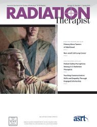
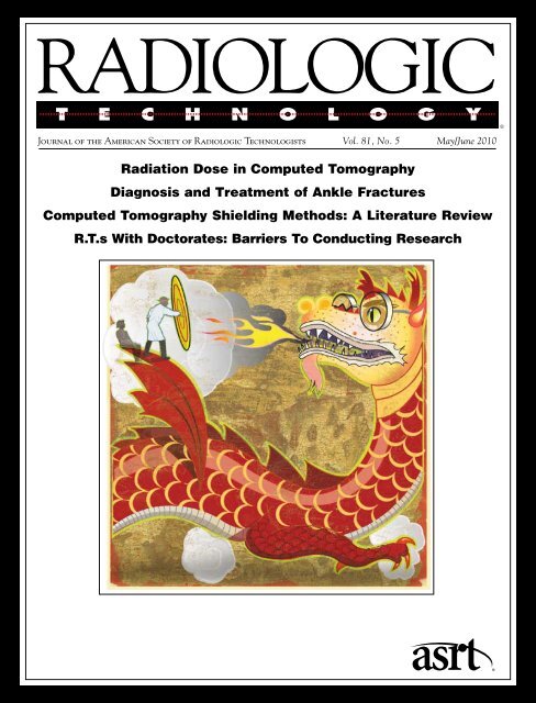
On the Cover: Cover<br />
artist Earl Keleny <strong>of</strong><br />
Madison, Wisconsin,<br />
wanted to represent the idea<br />
<strong>of</strong> protecting patients from<br />
excess radiation in a novel<br />
way. “I thought the dragon’s<br />
fire was an interesting<br />
metaphor for radiation,”<br />
he explained. “The figure<br />
with the shield represents<br />
the radiologic technologist<br />
guarding a patient.”<br />
Computed Tomography Shielding Methods:<br />
A Literature Review<br />
Jessica Ryann Curtis ..........................................428<br />
DIRECTED READING ARTICLES<br />
Radiation Dose in Computed Tomography<br />
Bryant Furlow ...............................................437<br />
Diagnosis and Treatment <strong>of</strong> Ankle Fractures<br />
Anne M Scott ................................................457<br />
COLUMNS & DEPARTMENTS<br />
Research & Technology ...................................483<br />
Special Report ............................................484<br />
On the Job ................................................491<br />
RE: Registry ..............................................499<br />
Literature Review .........................................502<br />
Writing & Research .......................................504<br />
Teaching Techniques .....................................506<br />
Patient Page ..............................................511<br />
416 May/June 2010, Vol. 81/No. 5 RADIOLOGIC TECHNOLOGY
...................................................................................................<br />
PEER REVIEW<br />
Survey <strong>of</strong> R.T.s With Doctorates:<br />
Barriers To Conducting Research<br />
KIMBERLY L METCALF, EdD, R.T.(R)(T)<br />
ROBERT D ADAMS, EdD, R.T.(R)(T), CMD<br />
BAHJAT QAQISH, MD, PhD<br />
JESSICA A CHURCH, BS, R.T.(R)(T)<br />
Background In today’s health care environment, the need to attract and retain doctorate-holding radiologic science practitioners<br />
and provide them the tools and resources necessary to pursue pr<strong>of</strong>essional research funding and publication cannot be underestimated.<br />
To date, however, there have been few studies on the possible barriers that interfere with both research and pr<strong>of</strong>essional publishing<br />
among these highly educated individuals. A review <strong>of</strong> the literature reveals that the overall lack <strong>of</strong> research and pr<strong>of</strong>essional<br />
publishing by radiologic science pr<strong>of</strong>essionals holding doctorates can itself become a barrier in that low academic productivity is<br />
associated with a perceived lack <strong>of</strong> pr<strong>of</strong>essionalism, lack <strong>of</strong> respect from external health pr<strong>of</strong>essions and the lack <strong>of</strong> creation <strong>of</strong> new<br />
knowledge.<br />
Purpose To characterize the barriers to publishing and research by doctorally prepared radiologic science practitioners using a<br />
national survey instrument. In addition, this study sought to measure the predictive value <strong>of</strong> select individual, workplace and<br />
leadership variables that could influence the ability <strong>of</strong> radiologic technologists and radiologic science educators to conduct research,<br />
publish their findings and seek grant funding for new research.<br />
Results We compared our survey findings for radiologic science practitioners to those <strong>of</strong> other health care groups in an attempt to<br />
determine which demographic variables may best be used to promote, rather than hinder, research, publishing and grant writing.<br />
The doctoral degree symbolizes the “pinnacle<br />
<strong>of</strong> advanced learning and scholarly enquiry,<br />
demonstrated by subject expertise and the<br />
creation <strong>of</strong> new knowledge.” 1 Furthermore,<br />
Conn suggested that attainment <strong>of</strong> a doctoral<br />
degree should be considered a minimum requirement<br />
for being able to conduct research and publish scholarly<br />
articles effectively. 2 Radiologic technologists with doctoral<br />
degrees make up only a small percentage <strong>of</strong> the<br />
<strong>American</strong> Registry <strong>of</strong> Radiologic Technologists (ARRT)-<br />
registered population. An ARRT report dated March 19,<br />
2009, stated that the number <strong>of</strong> credentialed technologists<br />
was 289 007 (K Hendricks, director <strong>of</strong> strategic<br />
communications at ARRT, oral communication, April<br />
20, 2009), and <strong>of</strong> this population, only 0.15% (n = 440)<br />
held doctorates. Expectations are that these individuals,<br />
however small a subset, should lead the way to knowledge<br />
building and future growth <strong>of</strong> the radiologic science<br />
pr<strong>of</strong>ession. 3,4 However, Legg and Fauber reported<br />
dismayingly low research and scholarship activity among<br />
radiologic technologists and other allied health pr<strong>of</strong>essionals<br />
holding doctorates. 3 Further, a lack <strong>of</strong> publishing<br />
was cited by Dowd as “the most common failure <strong>of</strong><br />
responsibility in radiologic science research.” 5 A lack <strong>of</strong><br />
research and publications typically is attributed to various<br />
barriers, both within and outside the workplace.<br />
With external recognition <strong>of</strong> the pr<strong>of</strong>ession hinging<br />
on the scholarly and research accomplishments <strong>of</strong> doctorate<br />
holders, 3 it becomes that much more important<br />
to identify barriers that impede scholarly productivity<br />
among members <strong>of</strong> this highly educated group.<br />
Accordingly, this study examines the factors that influence<br />
the research and pr<strong>of</strong>essional publication activity<br />
<strong>of</strong> doctorally prepared radiologic science practitioners,<br />
focusing on barriers within the workplace and possible<br />
factors that predict these barriers.<br />
Literature Review<br />
A literature search for “barriers to publication”<br />
identified a list <strong>of</strong> barriers potentially applicable to the<br />
RADIOLOGIC TECHNOLOGY May/June 2010, Vol. 81/No. 5<br />
417
...........................................................................................................<br />
BARRIERS TO RESEARCH<br />
radiologic sciences, and suggested that the ability to<br />
overcome or eliminate these obstacles was associated<br />
with greater academic productivity among doctorate<br />
holders in the form <strong>of</strong> research, publishing and grant<br />
writing. Although there were a number <strong>of</strong> articles specific<br />
to radiologic science educators, few studies related<br />
to radiologic science pr<strong>of</strong>essionals holding doctorates<br />
who were not educators. For that reason, articles specific<br />
to other doctoral-level, noneducator medical practitioners<br />
also were included and reviewed. While the barriers<br />
to research faced by pr<strong>of</strong>essionals in other areas <strong>of</strong><br />
medicine were not identical to those for pr<strong>of</strong>essionals<br />
in the radiologic sciences, there were several relevant<br />
similarities. Many <strong>of</strong> these barriers were considered in<br />
the development <strong>of</strong> our survey instrument.<br />
Sources for articles and dissertations included<br />
EBSCO Host; Biomedical Reference Collection: Basic,<br />
Pre-CINAHL, CINAHL; Health Source – Consumer<br />
Edition; Health Source – Nursing/Academic Edition;<br />
Nursing and Allied Health Collection; Medline; Psych<br />
Info; and ERIC databases. The time frame <strong>of</strong> the<br />
search was limited to the years 1988 to 2008.<br />
According to Willis, nurses typically face 2 types <strong>of</strong><br />
barriers when writing for publication. “Personal factors,<br />
such as inadequate knowledge and writing skills,<br />
lack <strong>of</strong> confidence, and low motivation for writing for<br />
publication, and situational factors, such as limited<br />
time, energy, and other resource constraints” commonly<br />
interfere with writing. 6 Willis further identified<br />
personal barriers, including thoughts and feelings,<br />
understanding <strong>of</strong> the writing and publication processes<br />
and personal work habits. Situational barriers include<br />
time and personal energy, as well as availability <strong>of</strong> other<br />
resources, such as emotional support, institutional culture,<br />
presence or absence <strong>of</strong> mentoring, size and quality<br />
<strong>of</strong> work space and financial support. 6<br />
Personal Barriers to Writing for Publication<br />
In a study by Pololi et al, personal barriers that physicians<br />
in academic medicine experienced included a<br />
lack <strong>of</strong> confidence in their writing ability and sensitivity<br />
to their writing being criticized by others. 7 These<br />
barriers are even more difficult to overcome for physicians<br />
who do not already have adequate research skills.<br />
As a rule, these skills are not taught in a consistent<br />
manner during medical school. 8,9 Typically, clinician<br />
educators were introduced to much research-oriented<br />
content during their medical training, yet invariably<br />
did not receive instruction on how to conduct research.<br />
According to Windish and Diener-West, “This can<br />
hinder clinician educators as they wish to develop, analyze<br />
and disseminate their scholarly work.” 10<br />
Situational Barriers to Writing for Publication<br />
One <strong>of</strong> the most commonly cited situational barriers<br />
to research activity is insufficient time to devote<br />
to writing. 9,11,12 In a general internal medicine residency<br />
program in which promotions were based on<br />
number <strong>of</strong> research publications, distractions such as<br />
travel, income tax returns, class preparation, family<br />
time on days <strong>of</strong>f and “other” were listed as reasons for<br />
not writing. 13 In organizations such as social service<br />
agencies, scholarly productivity is neither expected,<br />
rewarded, nor supported, financially or otherwise.<br />
Writing for scholarly publication is seen “as ‘nice’ but<br />
not necessary.” 7 Often, workloads are such that faculty<br />
members — women in particular — feel they have<br />
absolutely no time to write while at work. Instead, they<br />
find they must use time at home to squeeze in writing,<br />
frequently at the expense <strong>of</strong> family time. 14<br />
Situational barriers also include lack <strong>of</strong> support<br />
from college administration in the form <strong>of</strong> limited<br />
workspace, limited funding and lack <strong>of</strong> faculty mentoring<br />
for research and writing. 6,8,15 Levine et al found that<br />
“Lack <strong>of</strong> faculty time, … resident interest, and technical<br />
support” were major interferences with completing<br />
research. 11 “The interaction <strong>of</strong> age and experience<br />
on time required to prepare for classes during their<br />
younger years and time required to fulfill administrative<br />
tasks in their older years” is typical in academia 14<br />
and greatly influences the amount <strong>of</strong> time available<br />
for research activity. Researchers who are more experienced<br />
and successful should serve as role models for<br />
how to best integrate research into a busy schedule.<br />
Mentorship is an effective way for someone less experienced<br />
to learn from a more experienced peer. 17<br />
Overcoming Barriers to Publication<br />
Mentorship<br />
The <strong>American</strong> Heritage Dictionary defines a mentor<br />
as “a wise and trusted counselor or teacher.” 16<br />
Mentoring relationships are more prevalent today than<br />
20 years ago because faculty now have the added stress<br />
<strong>of</strong> adjusting to momentous and ongoing changes in<br />
education delivery, such as more widespread use <strong>of</strong> the<br />
Internet and online teaching. 17 Through mentoring,<br />
younger faculty can be coached by more senior peers<br />
in the ways <strong>of</strong> research. Fauber and Legg reported that<br />
when junior researchers are coached by more senior<br />
investigators, research productivity <strong>of</strong> the junior faculty<br />
418 May/June 2010, Vol. 81/No. 5 RADIOLOGIC TECHNOLOGY
...........................................................................................................<br />
METCALF, ADAMS, QAQISH, CHURCH<br />
member increases. 12 In medical programs in which<br />
research is supported, “senior faculty…are expected to<br />
help doctoral students and junior faculty to develop a<br />
successful academic career. Such success requires scholarly<br />
publication.” 13<br />
Other situational barriers include reluctance by<br />
faculty at 2-year community colleges to infringe on the<br />
territory <strong>of</strong> their counterparts at 4-year universities.<br />
Community college faculty consider scholarship as the<br />
responsibility <strong>of</strong> the universities and teaching the focus<br />
<strong>of</strong> community colleges. 15 Departmental expectations <strong>of</strong><br />
service on committees, teaching and increasing pressure<br />
to procure grant funding for research can put a<br />
great deal <strong>of</strong> strain on the pr<strong>of</strong>essional lives <strong>of</strong> medical<br />
and allied health faculty members. 15,18 This kind <strong>of</strong> lifestyle<br />
may well serve as a disincentive to take up scholarly<br />
research and publishing for many.<br />
Grant Funding<br />
The need for faculty to obtain grant funding is<br />
becoming more critical to support the overall research<br />
enterprise and for faculty seeking promotion or<br />
tenure. 6,19 Training in the grant writing process is one<br />
<strong>of</strong> the top career development needs <strong>of</strong> pr<strong>of</strong>essionals in<br />
the medical field. 12,18 The research dollars and career<br />
advancement obtained through successful grant writing<br />
more than compensate for the large investment<br />
<strong>of</strong> time and effort required to submit the grant. Legg<br />
and Fauber reported that in their study, respondents<br />
procured a total each <strong>of</strong> “more than $75 000 in grant<br />
money.” 3 For U.S. radiologic science education programs<br />
sponsored by institutions with 3-fold missions, “the pressure<br />
to publish and write grants is going to increase.” 20<br />
Further, Temme et al stated that, “compared with the<br />
traditional faculty model, including other allied health<br />
pr<strong>of</strong>essions, the vast majority <strong>of</strong> radiologic science education<br />
programs differ in that they do not have any type<br />
<strong>of</strong> accountability for publishing or research stimulus<br />
through pr<strong>of</strong>essional grant writing.” 20<br />
Methods<br />
A survey instrument was developed by the authors<br />
with input from a statistician to determine the most<br />
appropriate question design. The goal <strong>of</strong> this survey<br />
was to examine barriers that may influence the<br />
research and pr<strong>of</strong>essional publication activity <strong>of</strong> radiologic<br />
science practitioners holding doctorates. The<br />
survey questions were based largely on a literature<br />
review <strong>of</strong> factors frequently cited as barriers to conducting<br />
scholarly research in other health pr<strong>of</strong>essions.<br />
Questions addressing basic demographic and pr<strong>of</strong>essional<br />
information also were included. The instrument<br />
comprised a total <strong>of</strong> 25 closed-ended survey questions.<br />
Survey questions were divided into 3 sections.<br />
Section 1 was titled “Demographic Information,” and<br />
questions covered basic demographics, radiologic science<br />
occupation, membership in pr<strong>of</strong>essional organizations<br />
and specifics <strong>of</strong> doctoral education and training.<br />
The second section was titled “Organizational<br />
Information,” with questions focusing on employment<br />
status and location <strong>of</strong> employment. The third section<br />
was titled “Publication Leadership Information,” and<br />
included questions on publication activity, grant writing<br />
and funding and barriers to conducting research<br />
and publishing.<br />
A list <strong>of</strong> names and addresses <strong>of</strong> all ARRT-registered<br />
radiologic technologists holding doctorates was obtained<br />
from the ARRT. This mailing list included 440 names.<br />
After removing the first 2 authors’ names, the accessible<br />
population <strong>of</strong> doctorally prepared, ARRT-registered<br />
radiologic technologists totaled 438. The survey, along<br />
with a personalized cover letter explaining the purpose<br />
and significance <strong>of</strong> the study, was mailed to the 438<br />
radiologic technologists with doctorates. To encourage<br />
and facilitate response, a self-addressed, stamped envelope<br />
was included in each packet.<br />
Results<br />
A total <strong>of</strong> 438 surveys were mailed to radiologic<br />
technologists holding doctoral degrees; 163 surveys<br />
were completed and returned, yielding an overall<br />
response rate <strong>of</strong> 37% (n = 163).<br />
Limitations<br />
Several limitations must be acknowledged prior<br />
to interpreting these findings, or their generalizability<br />
to other health pr<strong>of</strong>essions. This study focused<br />
on the demographic pr<strong>of</strong>iles and scholarly achievements<br />
<strong>of</strong> radiologic technologists holding doctoral<br />
degrees, regardless <strong>of</strong> the type <strong>of</strong> doctoral degree<br />
or radiologic science specialty. The study population<br />
included all radiologic technologists with doctoral<br />
degrees currently certified by the ARRT. Those certified<br />
by other imaging-related registries such as the<br />
<strong>American</strong> Registry for Diagnostic Medical Sonography<br />
(ARDMS) or the Nuclear Medicine Technology<br />
Certification Board (NMTCB) were not included.<br />
Therefore, the findings <strong>of</strong> this study may not be generally<br />
applicable to radiologic technologists with doctoral<br />
degrees who have been certified by these other<br />
RADIOLOGIC TECHNOLOGY May/June 2010, Vol. 81/No. 5<br />
419
...........................................................................................................<br />
BARRIERS TO RESEARCH<br />
registries. In addition, because the workplace organization<br />
and required job skills vary sufficiently between<br />
sonography, nuclear medicine technology and other<br />
radiologic science specialties, it is possible that different<br />
barriers to scholarly productivity might exist.<br />
Demographic Information<br />
Demographic data for radiologic technologists holding<br />
doctorates are presented in Tables 1 and 2. All<br />
<strong>of</strong> the respondents confirmed that they had earned<br />
a doctoral degree. Three-fourths <strong>of</strong> the respondents<br />
were aged 40 to 59 years. The sex distribution was 54%<br />
female respondents and 45% male, with the remaining<br />
1% unspecified. At 84%, Caucasians composed the<br />
largest subgroup <strong>of</strong> respondents. African <strong>American</strong><br />
(4%) and Hispanic/Latino (4%) groups made up the<br />
next largest cohorts. The remaining 8% <strong>of</strong> respondents<br />
were from other ethnic minorities.<br />
At 67%, radiography was the largest primary radiologic<br />
science occupation for this group. The breakdown<br />
for the other primary occupations was as follows: nuclear<br />
medicine, 8%; radiation therapy, 7%; ultrasound, 5%;<br />
magnetic resonance imaging, 4%; and computed tomography,<br />
3%. The data showed that most <strong>of</strong> the respondents<br />
belonged to multiple pr<strong>of</strong>essional organizations.<br />
The respondents were divided evenly between those<br />
who had earned their doctorates prior to the year 2000<br />
and after 2000. Approximately 86% completed a thesis<br />
or dissertation as part <strong>of</strong> their doctoral studies. On the<br />
other hand, only 44% <strong>of</strong> respondents were required to<br />
complete a thesis or dissertation as part <strong>of</strong> their master’s<br />
degree program. A total <strong>of</strong> 80% <strong>of</strong> respondents<br />
completed their degree as traditional graduate students<br />
(66%) or through an executive program (12%);<br />
the other 20% earned their doctoral degree using an<br />
online or online/classroom format or in some other<br />
manner (2%). The specific doctoral degrees included<br />
the doctor <strong>of</strong> philosophy, PhD (47%); doctor <strong>of</strong> education,<br />
EdD (26%); doctor <strong>of</strong> jurisprudence, JD (15%);<br />
and doctor <strong>of</strong> medicine, MD (1%). A number <strong>of</strong> other<br />
doctoral degrees (11%) were included in the “other”<br />
category, such as doctor <strong>of</strong> ministry, DMin and doctor<br />
<strong>of</strong> pharmacy, PharmD.<br />
Workplace Factors<br />
Employment and workplace-related information<br />
for doctorally prepared radiologic science practitioners<br />
is presented in Table 3. The majority (86%) <strong>of</strong><br />
respondents worked full time, 4% worked part time or<br />
per diem, and the remaining 9% did not specify their<br />
Table 1<br />
Demographic Information: General<br />
Characteristic<br />
N (%) a<br />
Age (years)<br />
20-29 0<br />
30-39 12 (7)<br />
40-49 49 (31)<br />
50-59 71 (44)<br />
60-69 25 (16)<br />
Over 70 3 (2)<br />
Sex<br />
Female 87 (54)<br />
Male 73 (45)<br />
Ethnic Origin<br />
African <strong>American</strong>/Black 6 (4)<br />
Native Indian/Alaskan Native 3 (2)<br />
Caucasian/White 134 (84)<br />
Hispanic/Latino 6 (4)<br />
Asian 4 (3)<br />
Middle Eastern 2 (1)<br />
Other 5 (3)<br />
Primary Radiologic Science<br />
Occupation b<br />
Radiography 107 (67)<br />
Radiation therapy 11 (7)<br />
Nuclear medicine 12 (8)<br />
Ultrasound 8 (5)<br />
Magnetic resonance imaging 6 (4)<br />
Computed tomography 4 (3)<br />
Combination 5 (3)<br />
Other/no response 6 (4)<br />
a<br />
Percentages were rounded up to nearest whole number. Not<br />
every respondent indicated an answer to every question.<br />
employment status. Instead, they selected “other,”<br />
which included, for example, working in another<br />
industry, having retired or being unemployed.<br />
When asked to be more specific about their current<br />
job description, the following categories were noted:<br />
36% full-time educators, 26% other, 20% full-time<br />
420 May/June 2010, Vol. 81/No. 5 RADIOLOGIC TECHNOLOGY
...........................................................................................................<br />
METCALF, ADAMS, QAQISH, CHURCH<br />
Table 2<br />
Demographic Information: <strong>Education</strong> a<br />
Characteristic N (%)<br />
Type <strong>of</strong> Doctorate<br />
Philosophy (PhD) 75 (47)<br />
<strong>Education</strong> (EdD) 41 (26)<br />
Law (JD) 23 (15)<br />
Other: Pharmacy (PharmD), Ministry 18 (11)<br />
(DMin)<br />
Medicine (MD) 2 (1)<br />
When Doctorate Earned<br />
Before 1990 27 (17)<br />
1990 – 1995 26 (16)<br />
1996 – 2000 27 (17)<br />
2001 – 2009 80 (50)<br />
Dissertation Required in<br />
Doctoral Program<br />
Yes 136 (86)<br />
No 23 (14)<br />
Thesis Required in<br />
Master’s Program<br />
Yes 69 (44)<br />
No 69 (44)<br />
N/A 20 (12)<br />
Type <strong>of</strong> Doctoral Program<br />
Classroom only (traditional graduate 104 (66)<br />
student)<br />
Online only 13 (8)<br />
Online and classroom 18 (12)<br />
Executive (weeknights and/or<br />
18 (12)<br />
weekends)<br />
Other: changed programs,<br />
4 (2)<br />
independent study<br />
a<br />
Percentages were rounded up to nearest whole number. Not<br />
every respondent indicated an answer to every question.<br />
administrators, 9% full-time clinicians, 5% part-time clinicians<br />
and 1% part-time administrators. A wide range<br />
<strong>of</strong> responses was obtained for the “other” category; many<br />
<strong>of</strong> the respondents reported working in more than one<br />
radiologic science specialty/subspecialty. A number were<br />
Table 3 a<br />
Employment Information<br />
Characteristic N (%)<br />
Employment Status<br />
Full time (32-40 hrs/week) 137 (86)<br />
Part time (less than 32 hrs/week) 7 (4)<br />
Per diem 1 (1)<br />
Not specified 14 (9)<br />
Position<br />
Full-time clinician/practitioner 14 (9)<br />
Part-time clinician/practitioner 8 (5)<br />
Full-time educator 57 (36)<br />
Part-time educator 4 (3)<br />
Full-time administrator 32 (20)<br />
Part-time administrator 2 (1)<br />
Other: Outside <strong>of</strong> radiology 41 (26)<br />
Type <strong>of</strong> Institution<br />
Hospital 7 (8)<br />
College (2 year) 14 (16)<br />
University (4 year) 28 (31)<br />
Doctoral/research university 29 (32)<br />
Other 12 (13)<br />
Currently Tenured at Institution<br />
Yes 31 (25)<br />
No 59 (48)<br />
Not at institution 33 (27)<br />
Seeking a Tenure-track<br />
Appointment<br />
Yes 15 (14)<br />
No 70 (64)<br />
N/A; don’t have tenure<br />
24 (22)<br />
appointments<br />
a<br />
Percentages were rounded up to nearest whole number. Not<br />
every respondent indicated an answer to every question.<br />
involved in both the clinical arena and in academia. A<br />
number also reported working 2 part-time jobs, and others<br />
worked both a part-time job and a full-time job.<br />
Approximately 55% <strong>of</strong> those surveyed about their<br />
job indicated it includes at least some teaching. Of<br />
RADIOLOGIC TECHNOLOGY May/June 2010, Vol. 81/No. 5<br />
421
...........................................................................................................<br />
BARRIERS TO RESEARCH<br />
these respondents, 32% taught in graduate-level universities,<br />
31% taught in 4-year colleges, 16% taught in<br />
2-year colleges, and 8% taught in hospital-based training<br />
programs. The remaining 13% indicated a variety<br />
<strong>of</strong> teaching institutions, including medical colleges,<br />
Bible colleges, dental schools, fitness facilities, vocational<br />
or technical schools and even one-on-one tutoring<br />
<strong>of</strong> high school students. About 14% <strong>of</strong> those surveyed<br />
were working toward a tenure-track faculty appointment,<br />
but 64% were not. The other 22% responded<br />
“not applicable” (N/A). There were 31 (27%) respondents<br />
who already were tenured at their institution<br />
and 59 (48%) who were not. The remaining 33 (27%)<br />
indicated that tenure was either not an option for them<br />
at their institution or that they had retired as pr<strong>of</strong>essor<br />
emeriti with tenure (2%).<br />
Publication and Grants<br />
Publication and grantsmanship activities <strong>of</strong> doctorateholding<br />
radiologic science practitioners are presented in<br />
Table 4. Approximately 73% <strong>of</strong> respondents have published<br />
in pr<strong>of</strong>essional journals. Of all respondents, 32%<br />
had 1 to 3 publications, 16% had 4 to 5 publications,<br />
10% had 7 to 10 publications and 15% had more than<br />
10 publications in pr<strong>of</strong>essional journals. When asked<br />
whether they had submitted manuscripts that were not<br />
accepted, 71% <strong>of</strong> the group reported no unaccepted<br />
manuscripts. Thirty-seven (24%) had 1 to 3 manuscripts<br />
not accepted, 5 (3%) had 4 to 6 not accepted and 2 (1%)<br />
had 7 to 10 that were not accepted.<br />
A total <strong>of</strong> 125 <strong>of</strong> those surveyed responded to the<br />
question <strong>of</strong> whether they had ever applied for grant<br />
funding. Of these, 75 (60%) had not applied for a<br />
grant and 50 (40%) had. When asked whether they<br />
had ever been awarded grant funding, 50 respondents<br />
reported that they had received grant funding, which<br />
we could infer to mean 100% <strong>of</strong> those who applied<br />
for a grant received one. When asked how many total<br />
grant dollars had been awarded, nearly 25% <strong>of</strong> these<br />
respondents received more than $50 000 in grant<br />
funding (see Table 4 for a full breakdown). This totals<br />
to only 12 people out <strong>of</strong> not only doctorate-level R.T.s<br />
but <strong>of</strong> 220 000 certified pr<strong>of</strong>essionals.<br />
Only 13% <strong>of</strong> respondents reported being pressured<br />
by coworkers to include them as authors on manuscripts<br />
they were preparing for submission to pr<strong>of</strong>essional<br />
journals. Slightly more (17%) had experienced<br />
pressure from a direct supervisor or other individual in<br />
a higher position to include them as an author.<br />
Survey participants then were asked to rank on a<br />
4-point scale (from “yes,” to “maybe,” to “doubtful”<br />
to “no”) the extent to which a number <strong>of</strong> potential<br />
barriers identified through our literature review interfered<br />
with their own ability or willingness to conduct<br />
research and publish in scholarly journals. These<br />
results are shown in Table 5. The barriers identified by<br />
this group as interfering the most (selected by at least<br />
30% <strong>of</strong> respondents) with their scholarly productivity<br />
included the following:<br />
■ Lack <strong>of</strong>:<br />
• Time to write.<br />
• Energy or motivation to write.<br />
• Statistical technical support.<br />
• Faculty mentors.<br />
• Institutional or departmental support.<br />
• Funding.<br />
■ Limited knowledge <strong>of</strong> grant writing.<br />
■ Paperwork associated with grant writing.<br />
■ Research not being a job requirement.<br />
■ Research being viewed as low priority.<br />
■ Staff shortages at work.<br />
■ Major distractions such as travel.<br />
■ Competing job demands.<br />
Several other barriers were identified by respondents<br />
who selected “other.” These included not enjoying<br />
writing or not being a good writer, insufficient<br />
faculty to help distribute a heavy teaching load and life<br />
transitions such as having children, moving or changing<br />
jobs.<br />
Finally, survey respondents were asked about their<br />
comfort level with various skills typically required for<br />
successful writing for publication. These results are<br />
presented in Table 6. Most participants were quite comfortable<br />
with all but 1 <strong>of</strong> the components necessary for<br />
scholarly writing; approximately 30% indicated that<br />
they were uncomfortable with data analysis.<br />
Discussion<br />
The findings <strong>of</strong> this study suggest that, despite a<br />
stated desire to do so, many radiologic technologists<br />
holding doctoral degrees have conducted research or<br />
published in pr<strong>of</strong>essional journals only minimally, if<br />
at all. About 15% <strong>of</strong> this already-small group is doing<br />
most <strong>of</strong> the scholarly research and writing in the radiologic<br />
sciences. The majority <strong>of</strong> respondents (83%) were<br />
not feeling pressure from their employers to publish,<br />
and only 23% reported that their research and publication<br />
record was considered as part <strong>of</strong> their annual<br />
faculty review process. Employer pressure to seek grant<br />
422 May/June 2010, Vol. 81/No. 5 RADIOLOGIC TECHNOLOGY
...........................................................................................................<br />
METCALF, ADAMS, QAQISH, CHURCH<br />
Table 4 a<br />
Publications and Grants<br />
Characteristic N (%)<br />
Number <strong>of</strong> Publications in Pr<strong>of</strong>essional Journals<br />
None 43 (27)<br />
1-3 50 (32)<br />
4-6 25 (16)<br />
7-10 16 (10)<br />
More than 10 23 (15)<br />
Manuscripts Submitted but Not Accepted<br />
None 110 (72)<br />
1-3 37 (24)<br />
4-6 5 (3)<br />
7-10 2 (1)<br />
Pressure From Colleague To Be Included as Publication Author?<br />
Yes 21 (13)<br />
No 136 (87)<br />
Pressure From Superior To Be Included as Publication Author?<br />
Yes 27 (17)<br />
No 130 (83)<br />
Have Applied for Grant Funding?<br />
Yes 50 (40)<br />
No 75 (60)<br />
Been Awarded Grant Funding?<br />
Yes 50 (40)<br />
No 75 (60)<br />
If Yes, Size <strong>of</strong> Award?<br />
$1 – 999 3 (3)<br />
$1000 – $5000 4 (4)<br />
$5001 – $15 000 8 (8)<br />
$15 001 – $50 000 10 (10)<br />
$50 001 – $200 000 10 (10)<br />
Over $200 000 14 (14)<br />
Responded, but no amount listed 53 (51)<br />
a<br />
Percentages were rounded up to nearest whole number. Not every respondent indicated an answer to every question.<br />
RADIOLOGIC TECHNOLOGY May/June 2010, Vol. 81/No. 5<br />
423
...........................................................................................................<br />
BARRIERS TO RESEARCH<br />
Table 5 a<br />
Perceived Barriers to Research and Publishing<br />
Barrier Yes Maybe Doubtful No<br />
No. (%) No. (%) No. (%) No. (%)<br />
Lack <strong>of</strong> interest in research 13 (9) 23 (15) 55 (37) 58 (39)<br />
Research is not required for my job 52 (35) 26 (18) 23 (15) 47 (32)<br />
Research is a low job priority 43 (29) 38 (25) 25 (17) 43 (29)<br />
Lack <strong>of</strong> research skills 6 (4) 9 (6) 52 (35) 83 (55)<br />
Insufficient graduate education to develop research skills 5 (3) 8 (5) 40 (27) 97 (65)<br />
Research skills are outdated/rusty 6 (4) 28 (19) 47 (32) 67 (45)<br />
Lack <strong>of</strong> time to write 90 (60) 27 (18) 24 (16) 9 (6)<br />
Lack <strong>of</strong> energy or motivation to write 28 (19) 45 (30) 43 (29) 34 (22)<br />
Lack <strong>of</strong> ideas to write about 8 (6) 30 (20) 55 (37) 55 (37)<br />
Unfamiliar with publication process 7 (5) 21 (14) 48 (32) 74 (49)<br />
Managing anxiety/frustration during writing/publication process 8 (5) 29 (20) 58 (39) 53 (36)<br />
Discouraged by amount <strong>of</strong> editing/revisions required by journals 6 (4) 31 (21) 56 (37) 57 (38)<br />
Lack <strong>of</strong> statistical support 12 (8) 41 (27) 52 (35) 45 (30)<br />
Research findings not statistically significant 1 (1) 11 (7) 59 (40) 78 (52)<br />
Fear <strong>of</strong> rejection 4 (3) 19 (12) 44 (30) 83 (55)<br />
Lack <strong>of</strong> emotional support 6 (4) 20 (13) 42 (28) 81 (55)<br />
Difficulties with coauthor(s) 8 (5) 10 (7) 37 (25) 95 (63)<br />
Lack <strong>of</strong> faculty mentors 15 (10) 32 (22) 45 (30) 57 (38)<br />
Pressure by employer to publish 13 (9) 12 (8) 37 (25) 88 (58)<br />
Lack <strong>of</strong> departmental or institutional support 31 (21) 26 (18) 38 (25) 54 (36)<br />
Lack <strong>of</strong> funding 38 (26) 26 (17) 38 (26) 46 (31)<br />
Annual faculty review considers research and publication record 15 (10) 19 (13) 39 (26) 75 (51)<br />
Employer pressure to procure grant funding 13 (9) 15 (10) 34 (23) 87 (58)<br />
Limited knowledge <strong>of</strong> grant writing 20 (14) 32 (22) 45 (30) 51 (34)<br />
Paperwork/bureaucracy associated with grant writing 18 (12) 44 (30) 36 (25) 49 (33)<br />
Conflicts with committee work 27 (18) 35 (24) 42 (29) 43 (29)<br />
Staff shortages at work 43 (29) 33 (23) 40 (27) 30 (21)<br />
Major distractions (travel, competing work demands, etc.) 59 (40) 45 (30) 24 (16) 20 (14)<br />
Other 12 (70) 2 (12) -------- 3 (18)<br />
a<br />
Percentages were rounded up to nearest whole number and adjusted to allow for a total <strong>of</strong> 100%.<br />
funding was felt by only 19% <strong>of</strong> the survey respondents.<br />
Significant barriers have been identified that prevent<br />
doctorate-level radiologic science pr<strong>of</strong>essionals<br />
from pursuing academic research and writing, and<br />
fundamental changes in radiologic science education,<br />
training and perception will be needed if this trend is<br />
to be reversed. Among the impediments to research<br />
and pr<strong>of</strong>essional publication cited by these individuals<br />
424 May/June 2010, Vol. 81/No. 5 RADIOLOGIC TECHNOLOGY
...........................................................................................................<br />
METCALF, ADAMS, QAQISH, CHURCH<br />
are employers assigning<br />
a low priority<br />
to or lack <strong>of</strong> expectations<br />
regarding<br />
research productivity;<br />
a lack <strong>of</strong> specific<br />
training in how to<br />
write and publish<br />
effectively during doctoral<br />
training; and a<br />
lack <strong>of</strong> sound mentorship<br />
from both doctoral<br />
advisors during<br />
graduate school and<br />
more senior, experienced<br />
pr<strong>of</strong>essional<br />
colleagues in the<br />
workplace. In addition,<br />
there are the<br />
competing demands<br />
<strong>of</strong> balancing career<br />
with family life and,<br />
significantly, a perceived<br />
lack <strong>of</strong> respect<br />
Table 6 a<br />
Comfort Level With Factors Involved in Writing for Publication<br />
Barrier<br />
Comfort Level<br />
on the part <strong>of</strong> the larger health care enterprise, academia<br />
or both for the importance and value <strong>of</strong> scholarly<br />
activities by radiologic science educators.<br />
Less than 0.2% <strong>of</strong> all radiologic science pr<strong>of</strong>essionals<br />
have earned a doctorate degree — nearly 40% <strong>of</strong><br />
whom are educators — and <strong>of</strong> those, only 15% conduct<br />
research and publish with any regularity. When each <strong>of</strong><br />
these pr<strong>of</strong>essionals first decided to pursue a career in<br />
health care, they obviously developed a particular passion<br />
for radiologic science. As their careers progressed,<br />
this passion continued to motivate them to pursue 1 or<br />
more advanced degrees, culminating in a doctorate.<br />
Yet most <strong>of</strong> these uniquely motivated individuals’ passion<br />
to achieve further pr<strong>of</strong>essional development in the<br />
form <strong>of</strong> conducting research and publishing was overpowered<br />
by 1 or more barriers.<br />
An obvious mechanism to change this paradigm<br />
would be for the academic mentors <strong>of</strong> successful<br />
doctoral-level researchers and writers, as well as the<br />
individuals themselves, to give back voluntarily to their<br />
pr<strong>of</strong>ession by training others in the ways <strong>of</strong> research<br />
and pr<strong>of</strong>essional writing. Their drive for scholarly<br />
achievement, passion for language and communication,<br />
positive attitude and persistence and expertise<br />
in value-based research and the publication process<br />
could be invaluable to their peers who face academic<br />
Very<br />
Comfortable<br />
Somewhat<br />
Comfortable<br />
Somewhat<br />
Uncomfortable<br />
Very<br />
Uncomfortable<br />
No. (%) No. (%) No. (%) No. (%)<br />
Literature review 116 (79) 19 (13) 7 (5) 4 (3)<br />
Research design 61 (42) 60 (41) 19 (13) 6 (4)<br />
Statistical data analysis 43 (30) 57 (39) 30 (20) 16 (11)<br />
Composing abstract 94 (65) 34 (23) 15 (10) 3 (2)<br />
Proper use <strong>of</strong> citations 93 (64) 40 (27) 10 (7) 3 (2)<br />
Paraphrasing 94 (64) 39 (27) 9 (6) 4 (3)<br />
Designing tables 77 (53) 46 (32) 18 (12) 5 (3)<br />
Creating figures 76 (52) 40 (28) 23 (16) 6 (4)<br />
Adhering to journal format 69 (48) 43 (30) 24 (17) 8 (5)<br />
Formatting the bibliography 84 (58) 46 (32) 13 (9) 2 (1)<br />
a<br />
Percentages were rounded up to nearest whole number.<br />
obstacles, as well as to more junior educators in need<br />
<strong>of</strong> positive role models and mentors.<br />
Mentoring in the radiologic science pr<strong>of</strong>ession must<br />
take place on 3 levels. First, faculty members must mentor<br />
their radiologic science students through both didactic<br />
and clinical training. Second, practicing radiologic<br />
technologists and supervisors in the clinical setting must<br />
mentor radiologic science students by teaching and<br />
modeling proper clinical skills and pr<strong>of</strong>essional behavior.<br />
Third, radiologic science practitioners who conduct<br />
research and have published must be willing to share<br />
their experiences with others in the pr<strong>of</strong>ession.<br />
Radiologic science mentors must be willing to be<br />
generous with their time and expertise. Although a<br />
mentor can teach students or other practitioners how<br />
to write, conduct research, publish and deliver pr<strong>of</strong>essional<br />
presentations, the relationship is much more<br />
than simply “teaching.” One hopes that mentors have<br />
learned from their own career-related mistakes and<br />
developed unique coping strategies and skills, and can<br />
impart this knowledge to others. Providing knowledge,<br />
guidance and feedback allows important learning to<br />
occur. The educator as mentor should help develop<br />
the minds <strong>of</strong> students and colleagues, feed their curiosity,<br />
and provide the tools, skill sets and creativity<br />
needed to lead fulfilling pr<strong>of</strong>essional and academic<br />
RADIOLOGIC TECHNOLOGY May/June 2010, Vol. 81/No. 5<br />
425
...........................................................................................................<br />
BARRIERS TO RESEARCH<br />
lives. Ultimately, the mentor should help students or<br />
colleagues develop a strategic vision <strong>of</strong> what they can<br />
do, how they can do it and why the act <strong>of</strong> doing is so<br />
important not only for the individual, but also for the<br />
community at large.<br />
Doctorate-level radiologic technologists cite the<br />
desire to balance career with family life as another<br />
obstacle to being successful at research and pr<strong>of</strong>essional<br />
publishing. Striking a proper balance always is a daunting<br />
task, and one for which there is seldom a perfect<br />
solution. Also true, however, is the fact that successful<br />
researchers and writers have to, at times, “bring their<br />
work home with them,” especially when allowing time<br />
for such scholarly activities at work is either not valued<br />
or actively discouraged. Often, the consequences <strong>of</strong> lost<br />
family time because <strong>of</strong> the need to work can be minimized<br />
by, for example, using 1- to 2-hour blocks <strong>of</strong> time<br />
early in the morning to write. Family members still are<br />
asleep, which minimizes their resentment and keeps<br />
interruptions to a minimum. The writer is fresh, focused<br />
and motivated early in the day.<br />
Perhaps the most unfortunate consequence <strong>of</strong> the<br />
lack <strong>of</strong> research and publishing among radiologic science<br />
pr<strong>of</strong>essionals holding doctorates is the perception that<br />
the field must necessarily be “unpr<strong>of</strong>essional” or worse,<br />
lacks academic rigor. A vicious cycle could result from<br />
this perception, because these very misconceptions about<br />
radiologic sciences fuel the lack <strong>of</strong> respect from the<br />
greater health care or academic community that some in<br />
the radiologic sciences report as barriers to their career<br />
advancement as researchers and writers. Mentors can<br />
play an important role in this regard as well; they must<br />
demand academic rigor from their students, and constantly<br />
stress the importance <strong>of</strong> research and publication<br />
ethics, proper research methodology, critical-thinking<br />
skills, resourcefulness, connectedness, proactivity and<br />
pr<strong>of</strong>essional communication skills and conduct. It is only<br />
by example that a mentor can instill these values and<br />
positive work ethics in his or her students; however, these<br />
are skills that will serve the students for a lifetime. By<br />
doing so, mentors also arm their students with the tools<br />
to someday pass on this wisdom to the students’ peers<br />
and potentially their own students, and in so doing, help<br />
transform the pr<strong>of</strong>ession as a whole.<br />
References<br />
1. Ellis LB. Pr<strong>of</strong>essional doctorates for nurses: mapping provision<br />
and perceptions. J Adv Nurs. 2005;50(4):440-448.<br />
2. Conn VS. Postdoctoral research preparation. Western J<br />
Nurs Res. 2005;27(7):799-801.<br />
3. Legg JS, Fauber TL. Doctorally prepared R.T.s: a pr<strong>of</strong>essional<br />
pr<strong>of</strong>ile. Radiol Technol. 2001;72(3):209-220.<br />
4. Fauber TL, Legg JS. Research and scholarship among R.T.<br />
educators. Radiol Technol. 2003;74(5):376-384.<br />
5. Dowd SB, Schulz DL. Responsible dissemination <strong>of</strong> scholarly<br />
work in radiology. Radiol Technol.1996;67(5):407-414.<br />
6. Willis CE. Strategies for managing barriers to the writing<br />
process. Nurs Forum.2000;35(4):5-13.<br />
7. Pololi L, Knight S, Dunn K. Facilitating scholarly writing<br />
in academic medicine. J Gen Intern Med. 2004;19(1):64-68.<br />
8. Rivera JA, Levine RB, Wright SM. Brief report: completing<br />
a scholarly project during residency training. J Gen Intern<br />
Med. 2005;20(4):366-369.<br />
9. Grzybowski, SC, Bates J, Calam B, et al. A physician peer<br />
support writing group. Fam Med. 2003;35(3):195-201.<br />
10. Windish DM, Diener-West M. A clinician-educator’s roadmap<br />
to choosing and interpreting statistical tests. J Gen<br />
Intern Med. 2006;21(6):656-660.<br />
11. Levine RB, Hebert RS, Wright SM. Resident research and<br />
scholarly activity in internal medicine residency training<br />
programs. J Gen Intern Med. 2005;20(2):155-159.<br />
12. Fauber TL, Legg JS. Perceived research needs and barriers<br />
among R.T. educators. Radiol Technol. 2004;76(1):19-30.<br />
13. Neuhauser D, McEachern E, Zyzanski S, Flocke S, Williams<br />
RL. Continuous quality improvement and the process <strong>of</strong><br />
writing for academic publication. Qual Manag Health Care.<br />
2000;8(3):65-73.<br />
14. Buswell DJ, Sherrill C, French R, Myers B. Perspectives<br />
on publication among highly productive women<br />
adapted physical activity scholars. Adapt Phys Activ Q.<br />
2001;18:366-388.<br />
15. Williams DN. The role <strong>of</strong> scholarship in the community<br />
college. 1991. ERIC Digest ED3382904.<br />
16. The <strong>American</strong> Heritage Dictionary. 2nd College Ed. Boston,<br />
MA: Houghton Mifflin Company; 1985.<br />
17. Weigel C, Bugg N. Mentoring among faculty in higher education.<br />
Radiologic Science & <strong>Education</strong>. 2005;10(2):21-26.<br />
18. Miedzinski LF, Davis P, Al-Shurafa H, Morrison TC. A<br />
Canadian faculty <strong>of</strong> medicine and dentistry’s survey <strong>of</strong><br />
career development needs. Med Educ. 2001;35(9):890-900.<br />
19. Cole SS. Researcher behavior that leads to success in<br />
obtaining grant funding: a model for success. Research<br />
Management Review. 2006;15(2):1-16.<br />
20. Temme JB, Daniels M, Rush KL, Legg JS, Metcalf K,<br />
Adams RD. Educator’s dilemma: three-fold mission. Radiol<br />
Technol. 2009;81(1):1-3.<br />
Kimberly L Metcalf, EdD, R.T.(R)(T), is an assistant<br />
pr<strong>of</strong>essor for the medical imaging graduate certificate program<br />
at the Massachusetts General Hospital Institute <strong>of</strong> Health<br />
426 May/June 2010, Vol. 81/No. 5 RADIOLOGIC TECHNOLOGY
...........................................................................................................<br />
METCALF, ADAMS, QAQISH, CHURCH<br />
Pr<strong>of</strong>essions in Boston and a member <strong>of</strong> the Radiologic<br />
Technology Editorial Review Board. Robert D Adams, EdD,<br />
R.T.(R)(T), CMD, is assistant pr<strong>of</strong>essor in the Department <strong>of</strong><br />
Radiation Oncology and the program director for the radiation<br />
therapy and medical dosimetry programs at the University <strong>of</strong><br />
North Carolina (UNC) in Chapel Hill and a former member<br />
<strong>of</strong> the Radiation Therapist ERB. Bahjat Qaqish, MD, PhD,<br />
is an associate pr<strong>of</strong>essor in the UNC Department <strong>of</strong> Radiation<br />
Oncology. Jessica A Church, BS, R.T.(R)(T), is a graduate<br />
student in the UNC Department <strong>of</strong> Radiation Oncology.<br />
Reprint requests may be sent to the <strong>American</strong> <strong>Society</strong> <strong>of</strong><br />
Radiologic Technologists, Communications Department,<br />
15000 Central Ave SE, Albuquerque, NM 87123-3909, or<br />
e-mail communications@asrt.org.<br />
©2010 by the <strong>American</strong> <strong>Society</strong> <strong>of</strong> Radiologic Technologists.<br />
427
...................................................................................................<br />
PEER REVIEW<br />
Computed Tomography Shielding<br />
Methods: A Literature Review<br />
JESSICA RYANN CURTIS, BS, R.T.(R)(CT)<br />
Objective To investigate available shielding methods in an effort to further awareness and understanding <strong>of</strong> existing preventive measures<br />
related to patient exposure in computed tomography (CT) scanning.<br />
Methods Searches were conducted to locate literature discussing the effectiveness <strong>of</strong> commercially available shields. Literature containing<br />
information regarding breast, gonad, eye and thyroid shielding was identified. Because <strong>of</strong> rapidly advancing technology, the selection <strong>of</strong><br />
articles was limited to those published within the past 5 years. The selected studies were examined using the following topics as guidelines:<br />
the effectiveness <strong>of</strong> the shield (percentage <strong>of</strong> dose reduction), the shield’s effect on image quality, arguments for or against its use (including<br />
practicality) and overall recommendation for its use in clinical practice.<br />
Results Only a limited number <strong>of</strong> studies have been performed on the use <strong>of</strong> shields for the eyes, thyroid and gonads, but the evidence<br />
shows an overall benefit to their use. Breast shielding has been the most studied shielding method, with consistent agreement throughout<br />
the literature on its effectiveness at reducing radiation dose. The effect <strong>of</strong> shielding on image quality was not remarkable in a majority <strong>of</strong><br />
studies. Although it is noted that more studies need to be conducted regarding the impact on image quality, the currently published literature<br />
stresses the importance <strong>of</strong> shielding in reducing dose.<br />
Conclusion Commercially available shields for the breast, thyroid, eyes and gonads should be implemented in clinical practice. Further<br />
research is needed to ascertain the prevalence <strong>of</strong> shielding in the clinical setting.<br />
Advancing computed tomography (CT) technology<br />
and its increased utilization in clinical<br />
practice has created great interest within<br />
the health care community. A 2005<br />
report noted that CT scans constituted 11%<br />
<strong>of</strong> all medical x-ray exposures and contributed up to 67%<br />
<strong>of</strong> the general population’s total radiation dose. 1 These<br />
figures clearly indicate the high exposures associated<br />
with CT scanning. Concerns about exposure and<br />
increased utilization have led to several published studies<br />
on the potential for radiation-induced cancer risks.<br />
Often, radiosensitive tissues (ie, eye, thyroid gland and<br />
breast) are subjected to increased radiation doses because<br />
<strong>of</strong> their exposure to low-energy scattered photons and<br />
their superficial location and proximity to the field <strong>of</strong><br />
view. This is unfortunate, because these radiosensitive<br />
organs and tissues are exposed to radiation even though<br />
they <strong>of</strong>ten are not under direct diagnostic evaluation. 2<br />
Despite widely published information on doses and<br />
risks associated with CT scanning, many radiologists,<br />
physicians and technologists remain doubtful <strong>of</strong> the<br />
risks and believe they are insignificant. 3,4 A survey <strong>of</strong><br />
physicians’ attitudes about risks and benefits <strong>of</strong> chest CT<br />
concluded that more than 90% <strong>of</strong> physicians either do<br />
not know or significantly underestimate the radiation<br />
doses associated with its use. 2 The lack <strong>of</strong> understanding<br />
and acknowledgement <strong>of</strong> risks within the health care<br />
community has likely led to inconsistent and insufficient<br />
use <strong>of</strong> preventive measures such as shielding. For example,<br />
a study by Semelka et al on emergency departments<br />
described data showing that radiologists who performed<br />
CT examinations considered the radiation exposure to<br />
be <strong>of</strong> limited importance, and stated that radiologists<br />
were unaware <strong>of</strong> the amount <strong>of</strong> radiation that was delivered<br />
to patients by CT. 5<br />
A trickle-down effect <strong>of</strong> unawareness regarding<br />
radiation safety has become increasingly problematic<br />
within the medical field. This author deduced from the<br />
literature that because the physicians who order and set<br />
protocols for CT exams <strong>of</strong>ten are unaware or unconvinced<br />
<strong>of</strong> the potential risks, radiologic technologists<br />
and other staff members may be similarly uninformed<br />
<strong>of</strong> the risks. Furthermore, they may not be provided<br />
the necessary resources to further their education on<br />
risks and effective preventive measures.<br />
The purpose <strong>of</strong> this literature review is to examine<br />
the current research regarding the benefits and effectiveness<br />
<strong>of</strong> shielding for reducing risks to patients and<br />
improving safety when performing CT scans. Methods<br />
such as automatic exposure control and lowering tube<br />
428 May/June 2010, Vol. 81/No. 5 RADIOLOGIC TECHNOLOGY
...........................................................................................................<br />
CURTIS<br />
current have been discussed as effective techniques for<br />
dose reduction. Alternative methods, such as shielding,<br />
have received less attention in the literature. By researching<br />
the literature, concise recommendations can be<br />
developed to encourage the use <strong>of</strong> various shielding<br />
methods in clinical practice.<br />
Methods<br />
Searches were performed using the search engines<br />
PubMed and Cumulative Index to Nursing and Allied<br />
Health Literature. The following key terms were used<br />
in various combinations: CT, computed tomography,<br />
shielding, disadvantages, radiation safety and pediatric.<br />
The search produced a total <strong>of</strong> 501 articles. Because <strong>of</strong><br />
continuing advancements in technology, this literature<br />
review was limited to studies published in the past 5<br />
years. The search also was limited to articles published<br />
in English. The literature was further limited to articles<br />
that discussed shielding in CT, commercially available<br />
shields, including shields that met commercial standards<br />
based on manufacturer guidelines, and routine<br />
scans. After limiting the search, 9 relevant articles were<br />
identified for this literature review. Three articles discussing<br />
general information on CT dose and possible<br />
risks also were included, for a total <strong>of</strong> 12 articles.<br />
Information gathered from each article included the<br />
following: effectiveness <strong>of</strong> the shielding method (including<br />
percentage <strong>of</strong> dose reduction), effect on image quality<br />
(presence <strong>of</strong> artifacts and noise), general arguments<br />
for the shield’s practicality and the overall recommendation<br />
for use in the clinical setting. The data on dose<br />
reduction are presented for each study to account for the<br />
fact that all studies did not follow the same protocols or<br />
use the same equipment.<br />
Discussion<br />
Importance <strong>of</strong> Shielding<br />
A student perspective published in Radiologic<br />
Technology in 2007 by Voress stated, “Shielding is one <strong>of</strong><br />
the fundamental methods used to reduce patient dose<br />
during radiologic examinations, yet it is <strong>of</strong>ten forgotten<br />
when positioning a CT patient” 6 The amount <strong>of</strong> radiation<br />
received has increased with the rapidly advancing<br />
technology <strong>of</strong> CT. Acquisition speeds have increased<br />
and so has image quality. 7 In turn, use <strong>of</strong> CT scanning<br />
also has increased. 1 It is very important to take preventive<br />
measures to attempt to keep doses as low as reasonably<br />
achievable (ALARA).<br />
The biological effects <strong>of</strong> overexposure fall into 1 <strong>of</strong><br />
2 categories: stochastic effects (cell transforming) or<br />
deterministic effects (cell destroying). Deterministic<br />
effects have threshold doses, which means that effects<br />
do not occur below a certain dose. Above the threshold<br />
dose, the severity <strong>of</strong> the effects increases as the<br />
radiation dose increases. Stochastic effects are random<br />
effects from radiation that may cause cancer or genetic<br />
effects in irradiated individuals or their <strong>of</strong>fspring. 8 The<br />
published literature suggests that when discussing the<br />
risks associated with CT, the risk <strong>of</strong> stochastic effects<br />
is the main concern. However, this is not to say that<br />
deterministic effects are not possible. Debate continues<br />
on exactly how much <strong>of</strong> a risk is present for either type<br />
<strong>of</strong> effect. Any level <strong>of</strong> risk is important in discussing the<br />
need to shield, regardless <strong>of</strong> how high or low the risk.<br />
The International Commission on Radiological<br />
Protection (ICRP) has developed tissue weighting factors<br />
to provide a scale for the various sensitivities <strong>of</strong> tissues<br />
within the body. Not all <strong>of</strong> the organs within our<br />
bodies react the same way when exposed to comparable<br />
amounts <strong>of</strong> radiation. Certain tissues are particularly<br />
radiosensitive and carry a higher risk <strong>of</strong> mutagenic risks<br />
when exposed to certain levels <strong>of</strong> radiation. Assigning<br />
tissues a weighting factor allows estimates <strong>of</strong> the tissues’<br />
attributing risk to the body as a whole, in addition to the<br />
tissues’ individual risk for developing mutagenic effects.<br />
The breasts, gonads, thyroid and eyes are some <strong>of</strong> the<br />
most radiosensitive tissues in the body.<br />
In addition to organ-specific radiosensitivity, one<br />
must consider the patient’s age. The radiosensitivity<br />
<strong>of</strong> tissues and organs in children and young adults is<br />
one <strong>of</strong> the primary reasons to shield. The radiosensitive<br />
organs mentioned above are even more sensitive<br />
at younger ages. Cells divide and grow rapidly through<br />
young adulthood, which increases susceptibility to<br />
effects from radiation. 8 According to Hohl et al,<br />
“Infants and children are as much as 10 times more<br />
susceptible to carcinogenesis from radiation exposure<br />
than adults.” 7 For example, breast tissue exposed to<br />
radiation from CT is an area <strong>of</strong> particular concern in<br />
girls and young women. Populations exposed to radiation<br />
doses similar to those received from CT scans have<br />
demonstrated increased incidence <strong>of</strong> breast cancer.<br />
The risk <strong>of</strong> carcinogenesis is higher the younger the<br />
patient is when exposed to radiation. 7<br />
Although these issues regarding radiosensitivity are<br />
known, use <strong>of</strong> shielding for CT exams is not consistent<br />
in practice. It is possible that this is because conventional<br />
radiography shields are the only method available<br />
in a facility. In many practice settings, radiologic<br />
technologists may not know that commercially available<br />
RADIOLOGIC TECHNOLOGY May/June 2010, Vol. 81/No. 5<br />
429
...........................................................................................................<br />
CT SHIELDING METHODS<br />
in-plane bismuth shields have been created specifically<br />
for use in CT scanning.<br />
In-plane bismuth shields serve as an additional filter<br />
that is placed on especially sensitive areas. The shields<br />
<strong>of</strong>fer selective dose lowering for the underlying tissue,<br />
while still allowing enough x-ray beam to pass through<br />
to obtain a diagnostic image. 10 Hohl et al found that<br />
the intention <strong>of</strong> the thin in-plane bismuth shield is<br />
different from the thick conventional lead shields.<br />
Conventional lead shields attempt to completely absorb<br />
the radiation. The in-plane bismuth shield simply<br />
hardens the beam’s energy distribution to decrease the<br />
superficial dose produced by s<strong>of</strong>t radiation. Minimizing<br />
metal artifacts is an added benefit when using in-plane<br />
bismuth shields. 7<br />
The benefits mentioned above may not provide<br />
enough motivation to use shielding in CT. However,<br />
as pr<strong>of</strong>essionals, the ethical duty to abide by ALARA<br />
should. According to Hohl and Mahnken et al, “Any<br />
protection measure that is easy to use, does not impair<br />
image quality, and significantly reduces x-ray exposure<br />
should be used.” 11 Commercially available shields are<br />
easy to use, inexpensive and effective. Shielding radiosensitive<br />
superficial organs is a straightforward method<br />
<strong>of</strong> reducing radiation exposure. 7<br />
Shielding Methods<br />
The following sections discuss the commercially<br />
available shields that may be used during CT scanning.<br />
The discussion summarizes what the literature reported<br />
regarding the dose reductions that the shields provide,<br />
the effect on image quality and any debate concerning<br />
the shields’ use (eg, cost, ease <strong>of</strong> use, angling<br />
<strong>of</strong> the gantry or altering tube current). The discussion<br />
concludes with a concise chart showing when to implement<br />
the various shielding methods.<br />
Breast<br />
The breast tissue is among the most radiosensitive<br />
anatomy. Yilmaz et al stated that according to the<br />
study <strong>of</strong> Hopper et al, the average radiation dose to the<br />
breasts during thoracic CT was 0.022 Gy. 10 Fricke et al<br />
found that radiation dose to the breasts in the pediatric<br />
population during multidetector CT was 0.017 Gy.<br />
These doses greatly exceed the <strong>American</strong> College <strong>of</strong><br />
Radiology (ACR) recommendation <strong>of</strong> 0.003 Gy or less<br />
for a standard 2-view mammogram. 10 These statements<br />
exemplify the importance <strong>of</strong> breast shielding during<br />
CT scanning. Mammography, which uses lower levels<br />
<strong>of</strong> radiation than CT, has a mandated maximum for<br />
radiation exposure. A CT chest scan dose is more than<br />
3 times the typical mammography dose.<br />
Further, Parker et al mentioned that chest CT is<br />
not performed to obtain diagnostic information about<br />
the breast, but to gather information about the lung<br />
parenchyma and the mediastinum. 2 They also stated<br />
that dose to radiosensitive breast tissue is an unwanted<br />
byproduct because <strong>of</strong> the breasts’ superficial location. 2<br />
Grobe et al referred to a study <strong>of</strong> 1030 women with<br />
scoliosis who routinely underwent multiple thoracic<br />
spine radiography examinations as young girls. The<br />
study revealed a nearly 2-fold statistically significant<br />
increased risk for incidental breast lesions. 13 CT scanning<br />
uses a higher radiation dose than spinal radiography,<br />
which introduces possible implications from<br />
performing chest CTs with no shielding. Commercially<br />
available shields have been <strong>of</strong>fered to help reduce<br />
unnecessary exposure to the breast during CT.<br />
Four articles from the literature review discussed<br />
commercially available breast shields and their<br />
effectiveness (see Figure 1). These articles included<br />
assessments <strong>of</strong> shielding breasts <strong>of</strong> patients and on<br />
phantoms. Dose reduction ranged from 40.53% to<br />
61%. 2,7,10,12 These studies included various options for<br />
using spacers to improve image quality. A spacer is a<br />
foam insert placed between the patient and the shield<br />
to provide more distance between the shield and the<br />
patient. 7 Use <strong>of</strong> shielding without spacers caused some<br />
artifacts in the superficial tissues, but did not affect the<br />
diagnostic quality <strong>of</strong> the image. For example, Yilmaz<br />
et al noted minimal artifacts over the shield and breast<br />
tissue but not in the lung parenchyma. 10<br />
An article by Geleijns et al questioned the use <strong>of</strong> inplane<br />
bismuth shielding, stating that it contributes to<br />
significant noise. The authors contended that altering<br />
the tube current provides a better theoretical option for<br />
reducing radiation exposure. 12 However, this option is<br />
hypothetical and more research should be conducted<br />
to assess its true effectiveness compared with the statistically<br />
sound dose reductions found with the breast shield.<br />
There is overall agreement in the literature that breast<br />
shielding contributes to a significant reduction in patient<br />
overexposure to radiation and does not deteriorate<br />
image quality. However, the literature does not agree on<br />
the effects <strong>of</strong> breast shields on image quality. Therefore,<br />
more research in this area would be beneficial.<br />
Gonads<br />
The gonads are highly sensitive to radiation.<br />
Weighting factors are assigned to tissues in the body<br />
430 May/June 2010, Vol. 81/No. 5 RADIOLOGIC TECHNOLOGY
...........................................................................................................<br />
CURTIS<br />
Figure 1. Example <strong>of</strong> breast shield showing placement<br />
<strong>of</strong> the shield before computed tomography (CT) scanning<br />
begins. Image courtesy <strong>of</strong> AttenuRad CT Shields, F&L<br />
Medical Products, Vandergrift, PA.<br />
based on the tissues’ sensitivity to stochastic radiation<br />
damage. These factors help calculate<br />
effective dose. Despite the fact<br />
that the tissue weighting factor for<br />
gonadal tissue was decreased from<br />
0.20 to 0.08 in 2007, exposure still<br />
plays an important role in the effective<br />
dose. 13 The gonads carry risk <strong>of</strong><br />
mutagenesis, which makes shielding<br />
the testicles imperative. Grobe et al<br />
estimated thresholds for temporary<br />
sterility <strong>of</strong> men at 0.15 Sv for a single<br />
brief exposure or permanent sterility<br />
at 3.5 to 6 Sv. Temporary sterility<br />
could occur at 0.4 Sv for a single<br />
exposure or permanent sterility at 2.0<br />
Sv/year if the dose occurred in highly<br />
fractionated or protracted exposures<br />
for several years. 13 According to<br />
Hohl et al, shielding <strong>of</strong> the gonads<br />
has been a routine dose reduction<br />
method during conventional radiography for many<br />
years. However, gonadal shields are not widely used<br />
in routine CT scanning, possibly because it is considered<br />
difficult to protect the gonads from a multidirectional<br />
x-ray source. 11<br />
Two articles in the literature review discussed gonadal<br />
shielding. The literature and information on gonadal<br />
shielding is limited by the fact that research only has<br />
been published on male shielding. A study performed<br />
by Hohl et al used testicle capsules for shielding, which<br />
allowed for 360º shielding (see Figure 2). The study<br />
found testicle capsules reduced dose 87%. The study<br />
also found that the testicle capsules were easy to use,<br />
commercially available and well accepted by patients.<br />
In addition to being effective, the capsules did not<br />
impair image quality. The authors recommended testicle<br />
capsules for daily use in the clinical setting. 11<br />
A study by Grobe et al also used a commercially<br />
available method <strong>of</strong> testicular shielding that completely<br />
surrounded the testicles and resulted in a dose<br />
reduction <strong>of</strong> 96%. 13 The authors, however, did not<br />
recommend shielding <strong>of</strong> the gonads during a routine<br />
pelvic exam because <strong>of</strong> image quality degradation<br />
from artifacts. 13 They instead recommended the use<br />
<strong>of</strong> shielding when the gonads are subjected to scatter<br />
radiation during an upper pelvic or abdominal scan.<br />
Overall, the authors concluded that gonadal shielding<br />
is easy, safe, quick, inexpensive and effective at reducing<br />
dose to the gonads and that it should be included<br />
in clinical use. 13<br />
Figure 2. Two sizes <strong>of</strong> gonadal shields used to protect the testicles during CT scanning.<br />
Reprinted with permission from The <strong>American</strong> Journal <strong>of</strong> Roentgenology. Hohl<br />
C, Mahnken AH, Klotz E, et al. Radiation dose reduction to the male gonads during<br />
MDCT: the effectiveness <strong>of</strong> a lead shield. AJR Am J Roentgenol. 2005;184(1):128-130.<br />
RADIOLOGIC TECHNOLOGY May/June 2010, Vol. 81/No. 5<br />
431
...........................................................................................................<br />
CT SHIELDING METHODS<br />
The current literature discusses available gonadal<br />
shielding methods to protect patients from the multidirectional<br />
x-ray source associated with CT scanning.<br />
The shielding methods are easy to use and well tolerated<br />
by patients. The dose reduction values reported<br />
in the literature indicate that commercially available<br />
shields are effective. There is agreement that gonadal<br />
shielding should be incorporated into routine clinical<br />
use for abdominal and upper pelvic exams. However,<br />
the literature conflicts on whether shielding should<br />
be used during routine pelvic exams; more research<br />
should be conducted.<br />
Thyroid<br />
Three articles in the literature discussed commercially<br />
available thyroid shields for CT scanning. One<br />
study explored the effectiveness <strong>of</strong> an in-plane bismuth<br />
shield using a 1-cm spacer (not specified per manufacturer’s<br />
guidelines) to reduce the beam-hardening<br />
artifacts the shield may produce. 7 Scans also were<br />
performed using the shield without a spacer. Routine<br />
neck CT protocols were used and images were tested<br />
for noise to assess quality. The percentage <strong>of</strong> dose<br />
reduction for the thyroid gland using a shield without<br />
a spacer was 35.8% compared with 31.3% when using<br />
a spacer. The skin dose reduction was 45.5% without a<br />
spacer and 40.2% with a spacer.<br />
Hohl et al found evidence <strong>of</strong> significant beam<br />
hardening artifacts that reduced the image quality in<br />
the subcutaneous tissue when using thyroid shields.<br />
Using a spacer significantly reduced beam-hardening<br />
artifacts. 7 Whether to use spacers appears to remain<br />
debatable. The authors stated, “The comparison <strong>of</strong><br />
bismuth shielding with and without spacers showed<br />
that the spacer can effectively prevent deterioration <strong>of</strong><br />
the image quality in the superficial tissue due to beamhardening<br />
artifacts.” 7 However, the question remains<br />
<strong>of</strong> whether the superficial tissue is <strong>of</strong> diagnostic importance.<br />
One school <strong>of</strong> thought states that all anatomy<br />
scanned is <strong>of</strong> diagnostic importance, and the other says<br />
that the areas <strong>of</strong> interest are the only ones <strong>of</strong> diagnostic<br />
significance. 7 Hohl et al found that thyroid shields are<br />
easy to use, inexpensive and effective. The authors contend<br />
the thyroid should be shielded when CT scans <strong>of</strong><br />
the neck are performed. 7<br />
A second article by McLaughlin and Mooney<br />
reported on use <strong>of</strong> a commercially available shield,<br />
but not a spacer, which resulted in dose reduction <strong>of</strong><br />
57%. 9 The authors also noted that the artifacts produced<br />
by the thyroid shield were slightly distracting,<br />
Figure 3. Placement <strong>of</strong> a thyroid shield before CT scanning.<br />
Image courtesy <strong>of</strong> AttenuRad CT Shields, F&L<br />
Medical Products, Vandergrift, PA.<br />
but did not interfere with image interpretation. They<br />
found that the dose reduction was significant and that<br />
it correlated with a reduction in the overall risk <strong>of</strong> the<br />
patient developing cancer. Overall, they found use <strong>of</strong><br />
the thyroid shield to be beneficial with no loss <strong>of</strong> image<br />
quality. Furthermore, they stated that the shield is inexpensive<br />
and easy to use, making it suitable for routine<br />
clinical application. 9<br />
A third article by Geleijns et al found the beamhardening<br />
artifacts and noise caused by the shield<br />
to be fairly prominent in the images. 12 The authors<br />
concluded that the in-plane bismuth thyroid shield<br />
should not be used. They stated that a theoretically<br />
higher dose reduction could be achieved by altering<br />
the tube current and further that altering the tube current<br />
would yield the same level <strong>of</strong> artifacts and noise<br />
in the image, while reducing the dose even more. 12<br />
432 May/June 2010, Vol. 81/No. 5 RADIOLOGIC TECHNOLOGY
...........................................................................................................<br />
CURTIS<br />
Theoretically, altering the tube current may<br />
provide positive results. However, the recent<br />
literature appears to favor shielding as a<br />
proven method with statistically significant<br />
substantiation.<br />
More research should be performed on<br />
tube current modification as a supplemental<br />
dose reduction method. The use <strong>of</strong> foam<br />
spacers is mentioned in the literature, but<br />
a detailed discussion is lacking and more<br />
research would be beneficial. Despite uncertainties<br />
regarding use <strong>of</strong> spacers to improve<br />
image quality, the literature currently recommends<br />
the use <strong>of</strong> thyroid shielding during<br />
routine scans <strong>of</strong> the chest and neck with or<br />
without a spacer.<br />
Eyes<br />
When the eye is exposed to ionizing radiation,<br />
cells located at the front <strong>of</strong> the lens can<br />
be damaged or destroyed. The affected cells<br />
migrate to the back <strong>of</strong> the lens, where they<br />
can collect and form an opacity that may<br />
impair vision and lead to cataracts. 1 The lens<br />
<strong>of</strong> the eye is one <strong>of</strong> the most radiosensitive<br />
human tissues, according to the ICRP and the<br />
National Research Council’s Committee on<br />
the Biological Effects <strong>of</strong> Ionizing Radiation. 1<br />
Perisinakis et al explained that during a CT exam <strong>of</strong><br />
the head, the dose to the lens <strong>of</strong> the eye may range<br />
from 0.03 Gy to 0.13 Gy. 1 Further, the threshold for ophthalmologically<br />
detectable opacities following a single<br />
x-ray exposure has been reported to be 0.5 to 2 Gy. The<br />
National Radiological Protection Board has proposed a<br />
threshold value <strong>of</strong> 1.3 Gy for radiogenic induction <strong>of</strong> an<br />
eye lens cataract following acute x-ray exposures. 1<br />
These threshold values are for adults and may be<br />
even lower for infants and children. According to<br />
Persinakis et al, the head CT is a common exam ordered<br />
for pediatric patients, and more than 10% <strong>of</strong> all CT<br />
examinations are performed in infants and children<br />
aged 0 to15 years. The authors also reported that head<br />
CT scans constitute 45% <strong>of</strong> all CT scans performed. 1<br />
Head CTs are ordered to investigate trauma, tumors,<br />
congenital abnormalities, metabolic disorders and<br />
inflammatory lesions. 1 The accumulated doses combined<br />
with the frequency <strong>of</strong> head CTs and the radiosensitivity<br />
<strong>of</strong> the eye lens create a concern for adult patients<br />
and an even greater concern for pediatric patients.<br />
These findings make it imperative to shield the eyes<br />
during CT scans. Furthermore, to comply with the<br />
Figure 4. Placement <strong>of</strong> an eye shield during a CT scan. Image courtesy<br />
<strong>of</strong> AttenuRad CT Shields, F&L Medical Products, Vandergrift, PA.<br />
ALARA principle, it is important to follow any available<br />
method to reduce patient exposure. Angling the gantry<br />
reduces the dose to the lens, but not all exams allow for<br />
gantry angling. For example, orbital, sinus and mastoid<br />
studies do not allow the gantry to be angled to ensure<br />
proper representation <strong>of</strong> possible air-fluid levels. The<br />
radiologic technologist should angle the gantry only if<br />
the patient cannot be positioned properly. The use <strong>of</strong><br />
lead shields for the eyes is important in these studies<br />
because the lens <strong>of</strong> the eye <strong>of</strong>ten is included in the scan<br />
field but is rarely the organ <strong>of</strong> interest (see Figure 4). 1,9<br />
Four studies were identified in the literature review<br />
that discussed the use <strong>of</strong> commercially available shields<br />
for the eyes. Some focused primarily on the percentage<br />
<strong>of</strong> dose reduction, although others also included<br />
the shields’ effects on image quality. At least one study<br />
explored shield use for adult or pediatric patients.<br />
Studies were performed on phantoms and patients.<br />
Radiation dose was monitored through the use <strong>of</strong><br />
thermoluminescent dosimeters (TLDs). The studies<br />
explored various shielding positions to determine the<br />
position that reduced dose most yet maintained optimal<br />
image quality.<br />
RADIOLOGIC TECHNOLOGY May/June 2010, Vol. 81/No. 5<br />
433
...........................................................................................................<br />
CT SHIELDING METHODS<br />
The studies reported some variation in the percentage<br />
<strong>of</strong> dose reduction, but in general agreed that the<br />
shields reduced the amount <strong>of</strong> radiation exposure to the<br />
lens <strong>of</strong> the eye. For example, a study on pediatric phantoms<br />
by Perisinakis et al found that shielding in combination<br />
with angling the gantry reduced dose < 1%. 1 In<br />
contrast, the dose reductions <strong>of</strong> nonangled scans ranged<br />
from 33.1% to 37.4% for pediatric patients aged infant<br />
to 15 years, with an average <strong>of</strong> 34%. 1<br />
A study by Grobe et al found a 28.2% to 43.2%<br />
reduction in dose to the lens in men. 13 Other studies,<br />
such as one by McLaughlin and Mooney, found an<br />
18% dose reduction in adults. 9 Perisinakis et al noted<br />
that the shield did not lead to significant additional<br />
dose reduction because the gantry was angled in their<br />
study. 1 Despite differences in the percentage <strong>of</strong> dose<br />
reduction, the studies generally concluded that the<br />
shields significantly reduced dose to the lens <strong>of</strong> the eye,<br />
specifically when the gantry was not angled.<br />
The evidence suggests that eye shielding has a negligible<br />
effect on image quality. Perisinakis et al stated<br />
that the shield did not cause any significant artifacts<br />
and did not affect the images’ diagnostic value. 1 Grobe<br />
et al concluded that in the absence <strong>of</strong> other restrictions,<br />
such as reduced image quality caused by artifacts<br />
in the vicinity <strong>of</strong> the shielding, use <strong>of</strong> shields is<br />
advisable, especially if the eyes are directly exposed. 13<br />
McLaughlin and Mooney found that the eye, and therefore<br />
the eye shields, typically were not included in the<br />
imaging field and therefore did not affect image quality.<br />
9 If slight artifacts were present, they did not affect<br />
the diagnostic quality <strong>of</strong> the image. 9<br />
The study by Geleijns et al was the only study that<br />
concluded eye shields should not be used. The authors<br />
acknowledged that the noise created by the eye shield<br />
has only a modest effect on image quality and that the<br />
shield reduced dose by 27%. 9 However, they also stated<br />
that the threshold dose for radiation-induced cataracts<br />
is never reached when performing CT brain scans, even<br />
when multiphase scans are performed. 12 The authors<br />
maintained that the 27% reduction in lens dose achieved<br />
by selective shielding may be <strong>of</strong> minor importance in<br />
avoiding radiation-induced cataracts. Image artifacts,<br />
costs and extra waste caused by the disposable eye shields<br />
are additional arguments against the use <strong>of</strong> eye shields. 9<br />
However, the authors also stated that the increase in<br />
noise caused by the eye shields was “only modest.” 12<br />
Geleijns et al suggested the use <strong>of</strong> tube current modulation<br />
as a better alternative, given its theoretical success.<br />
More research needs to be conducted to assess which is a<br />
more beneficial dose reduction method. 12<br />
There is agreement in the literature that dose reduction<br />
to the eye lens depends on the position <strong>of</strong> the<br />
shield, whether the eye is being scanned through the<br />
primary beam and whether the gantry is angled. The<br />
overall impression from the literature is that shielding<br />
<strong>of</strong> the eyes when the gantry cannot be angled is important<br />
when performing routine scans <strong>of</strong> the head.<br />
Conclusion<br />
This literature review investigated commercially<br />
available shielding methods. The literature revealed<br />
consistent debate regarding altering the tube current<br />
in place <strong>of</strong> using shields; it also revealed that such<br />
suggestions were based on theoretical data. Based on<br />
a review <strong>of</strong> the literature, shielding provides statistically<br />
significant dose reductions for the breast, thyroid<br />
gland, eye and gonads. Further, it was reported that<br />
the shielding methods available for use in CT are costeffective<br />
and easy to use.<br />
There were discrepancies in the literature regarding<br />
the effects on image quality when using breast, gonadal<br />
and thyroid shields. Consequently, additional research<br />
should be devoted to exploring the effects on image<br />
quality in more detail. It appears from the current literature<br />
that the effects on image quality are minimal<br />
and the use <strong>of</strong> shields should not be impeded.<br />
Based on the data present in the literature, it is this<br />
author’s contention that commercially available shielding<br />
methods should be adopted into routine clinical<br />
practice. The Table summarizes the suggestions for<br />
shielding reported in the literature.<br />
The biological effects <strong>of</strong> ionizing radiation and the<br />
difference between stochastic and deterministic effects<br />
have been discussed thoroughly in the published literature.<br />
Although the evidence is not definitive regarding<br />
potential carcinogenic or mutagenic effects from the<br />
doses <strong>of</strong> radiation received when undergoing a CT<br />
scan, this does not suggest that currently available preventive<br />
measures should not be taken. The history <strong>of</strong><br />
medicine is replete with evidence-based research and<br />
recognition that detailed data may lead to changes in<br />
practice for the sake <strong>of</strong> patient safety. Radiation exposure<br />
should not be any different.<br />
The possibility <strong>of</strong> radiation-induced carcinogenesis<br />
is real and we all must be proactive in its prevention. In<br />
the example <strong>of</strong> women who had routinely undergone<br />
multiple thoracic spine radiography examinations<br />
as young girls for scoliosis screening, data revealed a<br />
434 May/June 2010, Vol. 81/No. 5 RADIOLOGIC TECHNOLOGY
...........................................................................................................<br />
CURTIS<br />
Table<br />
Computed Tomography Shielding Suggestions<br />
Radiosensitive Organ Examinations That Should<br />
Include Shielding<br />
Eyes<br />
Routine, vascular, orbital,<br />
sinus and mastoid studies<br />
Thyroid<br />
Routine chest and neck<br />
studies<br />
nearly 2-fold increased risk for breast cancer. 13 It can<br />
be argued that there is not enough evidence to deduce<br />
similar results from higher doses and inadequate<br />
shielding in CT examinations, but on the other hand,<br />
there is no evidence discounting the effects <strong>of</strong> radiation<br />
from CT scans.<br />
Implications for Further Research<br />
It is apparent from the literature review that there<br />
are many gaps in research and practice. The following<br />
suggestions recommend where pr<strong>of</strong>essionals in the<br />
field should focus their energy to ensure that patients<br />
are being exposed to as little radiation as possible when<br />
having a CT scan.<br />
This literature review investigated commercially<br />
available shielding methods. Other methods, such as<br />
automatic exposure control, altering tube currents or<br />
these methods combined with the use <strong>of</strong> shielding,<br />
were not within the scope <strong>of</strong> this review. However, these<br />
methods should be reviewed in future research because<br />
they may reduce patient dose even further.<br />
Further research also is needed to explore the<br />
frequency <strong>of</strong> use <strong>of</strong> various dose reduction methods.<br />
The literature has not addressed precisely what<br />
shields are available in the clinical setting or how<br />
they are being used. Nor has the literature addressed<br />
whether the tube current is being modified to reduce<br />
dose when shields are not used. These questions are<br />
<strong>of</strong> primary importance in a discussion <strong>of</strong> ways to<br />
reduce radiation-induced cancer risks for patients<br />
undergoing CT scanning.<br />
A better assessment <strong>of</strong> pediatric shielding needs to<br />
occur because the majority <strong>of</strong> the literature focuses<br />
on the use <strong>of</strong> shields on adults. The literature indicates<br />
that pediatric patients are at increased risk for<br />
radiation-induced cancer, yet studies have been geared<br />
primarily toward adults.<br />
Exceptions<br />
When gantry can be angled<br />
to avoid direct beam to lens<br />
None<br />
Gonads Abdomen, upper pelvis Routine pelvis<br />
Breasts Chest None<br />
Image quality<br />
as it relates to use<br />
<strong>of</strong> shields with CT<br />
scanning needs to<br />
be investigated in<br />
more detail. Many<br />
questions arise in the<br />
literature when discussing<br />
image quality<br />
and published information<br />
on this topic<br />
is vague. There is disagreement<br />
regarding<br />
the use <strong>of</strong> shields for the breasts, gonads and thyroid.<br />
Disagreement concerns the use <strong>of</strong> spacers to improve<br />
image quality <strong>of</strong> superficial tissues, whether superficial<br />
tissues are considered diagnostically significant and the<br />
general effects <strong>of</strong> shields on image quality.<br />
According to the literature, the use <strong>of</strong> spacers would<br />
improve image quality and still ensure dose reduction<br />
for the patient. However, it is not clear exactly how<br />
much image quality will be improved. It also is unclear<br />
from the literature exactly how much image quality<br />
currently is affected. Further investigation <strong>of</strong> these topics<br />
would be beneficial.<br />
Deterioration in image quality from shielding <strong>of</strong>ten<br />
was found in the superficial tissues in published studies,<br />
although some <strong>of</strong> the effects were not <strong>of</strong> diagnostic<br />
importance. It is imperative to determine what is considered<br />
“diagnostically important” when assessing the<br />
effects shields have on image quality. More research<br />
should be conducted to assess the effects shields have<br />
on the diagnostic quality <strong>of</strong> the images.<br />
Additional areas for future research include: gonadal<br />
shielding for women (to prevent sterility, cancer and<br />
other possible effects), gonadal shielding for routine<br />
pelvic exams, an age cut<strong>of</strong>f for the use <strong>of</strong> the breast<br />
shield and shielding <strong>of</strong> radiosensitive areas that are<br />
exposed to scatter radiation (ie, wraparound shielding<br />
<strong>of</strong> pediatric patients during CT brain scans).<br />
Despite the gaps in the literature, and until more<br />
definitive research has been performed, it is imperative<br />
that imaging pr<strong>of</strong>essionals take the necessary steps to<br />
follow ALARA and to protect patients from radiation<br />
when possible. The shielding methods mentioned in<br />
this literature review should be adopted into routine<br />
clinical use. It is clear that shielding can reduce dose<br />
and is inexpensive and easy to use. Radiosensitive<br />
structures such as the thyroid, breasts, eyes and gonads<br />
should be shielded during routine CT scans. Until data<br />
RADIOLOGIC TECHNOLOGY May/June 2010, Vol. 81/No. 5<br />
435
...........................................................................................................<br />
CT SHIELDING METHODS<br />
from further research are available, radiologic technologists<br />
should take the time to shield. By using shields,<br />
they help protect their patients from unnecessary radiation<br />
exposure without sacrificing diagnostic quality <strong>of</strong><br />
the images.<br />
References<br />
1. Perisinakis K, Raissaki M, Theocharopoulos N, Damilakis<br />
J, Gourtsoyiannis N. Reduction <strong>of</strong> eye lens radiation dose<br />
by orbital bismuth shielding in pediatric patients undergoing<br />
CT <strong>of</strong> the head: A Monte Carlo study. Med Phys.<br />
2005;32(4):1024-1030.<br />
2. Parker MS, Kelleher NM, Hoots JA, Chung JK, Fatouros PP,<br />
Benedict SH. Absorbed radiation dose <strong>of</strong> the female breast<br />
during diagnostic multidectector chest CT and dose reduction<br />
with a tungsten-antimony composite breast shield:<br />
preliminary results. Clin Radiol. 2008;63(3):278-288.<br />
3. Shah NB, Platt SL. ALARA: Is there a cause for alarm?<br />
Reducing radiation risks from computed tomography scanning<br />
in children. Curr Opin Pediatr. 2008;20(3):243-247.<br />
4. Frush DP. Computed tomography: important considerations<br />
for pediatric patients. Expert Rev Med Devices.<br />
2005;2(5):567-575.<br />
5. Semelka RC, Armao DM, Elias J Jr , Huda W. Imaging<br />
strategies to reduce the risk <strong>of</strong> radiation in CT studies,<br />
including selective substitution with MRI. J Magn Reson<br />
Imaging. 2007;25(5):900-909.<br />
6. Voress M. The increasing use <strong>of</strong> CT and its risks. Radiol<br />
Technol. 2007;79(2):186-190.<br />
7. Hohl C, Wildberger JE, Suss C, et al. Radiation dose<br />
reduction to breast and thyroid during MDCT: effectiveness<br />
<strong>of</strong> an in-plane bismuth shield. Acta Radiol.<br />
2006;47(6):562-567.<br />
8. Huda W, Ravenel J, Scalzetti EM. How do radiographic<br />
techniques affect image quality and patient doses in CT?<br />
Semin Ultrasound CT MR. 2002;23(5):411-422.<br />
9. McLaughlin DJ, Mooney RB. Dose reduction to radiosensitive<br />
tissues in CT. Do commercially available shields meet<br />
the users’ needs? Clin Radiol. 2004;59:446-450.<br />
10. Yilmaz MH, Albayram S, Yasar D, et al. Female breast radiation<br />
exposure during Thorax multidetector computed<br />
tomography and the effectiveness <strong>of</strong> bismuth breast shield<br />
to reduce breast radiation dose. J Comput Assist Tomogr.<br />
2007;31(1):138-142.<br />
11. Hohl C, Mahnken AH, Klotz E, et al. Radiation dose reduction<br />
to the male gonads during MDCT: the effectiveness <strong>of</strong><br />
a lead shield. AJR Am J Roentgenol. 2005;184(1):128-130.<br />
12. Geleijns J, Salvado Artells M, Veldkamp WJ, Lopez Tortosa<br />
M, Calzado Cantera A. Quantitative assessment <strong>of</strong> selective<br />
in-plane shielding <strong>of</strong> tissues in computed tomography<br />
through evaluation <strong>of</strong> absorbed dose and image quality.<br />
Eur Radiol. 2006;16(10):2334-2340.<br />
13. Grobe H, Sommer M, Koch A, Hietschold V, Henniger<br />
J, Abolmaali N. Dose reduction in computed tomography:<br />
the effect <strong>of</strong> eye and testicle shielding on radiation<br />
dose measured in patients with beryllium oxide-based<br />
optically stimulated luminescence dosimetry. Eur Radiol.<br />
2009;19(5):1156-1160.<br />
Jessica Ryann Curtis, BS, R.T.(R)(CT), graduated in May<br />
2009 from the University <strong>of</strong> North Carolina (UNC) in Chapel<br />
Hill with a bachelor <strong>of</strong> science degree in radiologic science. She<br />
is a CT imaging specialist at UNC Health Care.<br />
Reprint requests may be sent to the <strong>American</strong> <strong>Society</strong> <strong>of</strong><br />
Radiologic Technologists, Communications Department,<br />
15000 Central Ave SE, Albuquerque, NM 87123-3909, or<br />
e-mail communications@asrt.org.<br />
©2010 by the <strong>American</strong> <strong>Society</strong> <strong>of</strong> Radiologic Technologists.<br />
436 May/June 2010, Vol. 81/No. 5 RADIOLOGIC TECHNOLOGY
..................................................................................................<br />
CE<br />
DIRECTED READING<br />
Radiation Dose in<br />
Computed Tomography<br />
BRYANT FURLOW, BA<br />
The emergence <strong>of</strong> CT scanning<br />
as a routine diagnostic<br />
and radiation therapy<br />
planning tool has improved<br />
patient care by increasing the<br />
anatomic detail and diagnostic<br />
information available<br />
to clinicians. An increase in<br />
patient demand, availability<br />
and reimbursement practices<br />
have contributed to a dramatic<br />
escalation in the number<br />
<strong>of</strong> scans performed each<br />
year, and the risk and clinical<br />
justification for many <strong>of</strong> these<br />
procedures now is under<br />
debate. This <strong>Directed</strong> <strong>Reading</strong><br />
will review recent events<br />
and trends in CT imaging<br />
and patient radiation dose,<br />
dosimetry, the biological effects<br />
<strong>of</strong> ionizing radiation, the<br />
principles <strong>of</strong> radiation safety<br />
and strategies for managing<br />
patient dose.<br />
This article is a <strong>Directed</strong><br />
<strong>Reading</strong>. Your access to<br />
<strong>Directed</strong> <strong>Reading</strong> quizzes for<br />
continuing education credit<br />
is determined by your area <strong>of</strong><br />
interest. For access to other<br />
quizzes, go to www.asrt.org<br />
/store.<br />
After reading this article, readers should be able to:<br />
■ Identify recent trends in CT utilization.<br />
■ Compare and contrast how CT and radiography exams contribute to cumulative patient<br />
radiation exposures.<br />
■ Explain the role <strong>of</strong> patient age and gender in modulating the lifetime cancer risks from radiation<br />
exposures.<br />
■ Describe the role <strong>of</strong> distance, duration and protection in applying the as low as reasonably achievable<br />
principle.<br />
■ Summarize competing models <strong>of</strong> radiation risk.<br />
■ Discuss how pencil ionization chambers calculate patient radiation dose.<br />
■ Describe the competing imperatives <strong>of</strong> image quality and minimized radiation dose, along with CT<br />
scan variables that modulate dose.<br />
In October 2009, the U.S. Food<br />
and Drug Administration (FDA)<br />
issued a nationwide alert that<br />
advised hospitals to review safety<br />
protocols for computed tomography<br />
(CT) scans. This warning followed<br />
the discovery that a hospital in<br />
California had inadvertently exposed<br />
206 patients to elevated CT radiation<br />
doses over an 18-month period 1 during<br />
scans ordered to assess suspected<br />
strokes. Two months later, the FDA<br />
announced that additional cases had<br />
been identified at the hospital, and<br />
that at least 256 patients had received<br />
up to 8 times the intended radiation<br />
doses. 2<br />
The magnitude <strong>of</strong> the radiation<br />
overdoses and their effect on patients<br />
were described by the FDA as “significant.”<br />
At least 82 patients experienced<br />
skin burns (reddening) and patchy<br />
hair loss, and affected patients face<br />
a possible increased cataract risk. In<br />
December 2009, the FDA announced<br />
that it was investigating similar reports<br />
<strong>of</strong> CT radiation overdoses at undisclosed<br />
facilities in other states. 2<br />
“This situation may reflect more<br />
widespread problems with CT quality<br />
assurance programs and may not be<br />
isolated to this particular facility or this<br />
imaging procedure,” the FDA advisory<br />
warned. 2 Although early reports indicated<br />
that equipment malfunction caused<br />
the incidents, the FDA subsequently<br />
announced that the overdoses involved<br />
CT imaging equipment from more than<br />
1 manufacturer. This fact suggested that<br />
human error and lapses in safety practices<br />
and protocols, rather than faulty<br />
equipment, caused the errors. The<br />
FDA urged hospitals to report similar<br />
adverse events via its MedWatch Web<br />
site (www.fda.gov/Safety/MedWatch<br />
/HowToReport/default.htm). 2<br />
RADIOLOGIC TECHNOLOGY May/June 2010, Vol. 81/No. 5<br />
437
..................................................................................................<br />
CE<br />
RADIATION DOSE IN CT<br />
Regulatory Response<br />
In February 2010, the FDA announced a sweeping<br />
new regulatory initiative to reduce medical radiation<br />
exposures from CT scans and nuclear medicine and<br />
fluoroscopy procedures. 3 Citing patients’ increasing<br />
lifetime medical radiation doses, the agency declared<br />
its goal <strong>of</strong> eliminating unnecessary imaging procedures<br />
and ensuring the “careful optimization” <strong>of</strong> medically<br />
necessary imaging exams. Planned regulations were<br />
announced, including new requirements that CT scanners<br />
and fluoroscopic equipment record and display<br />
settings and dose for each scan performed and that<br />
patient doses be stored permanently in electronic<br />
health records.<br />
As part <strong>of</strong> an FDA patient education initiative,<br />
the agency also announced development <strong>of</strong> a patient<br />
medical imaging history card, distributed via the FDA<br />
Web site, that will allow patients to track their imaging<br />
history and present it to referring physicians. 3 The<br />
FDA also declared its support for a national dose registry<br />
and revised, uniform accreditation for radiology<br />
departments. 4<br />
“Each patient should get the right imaging exam,<br />
at the right time, with the right radiation dose,” the<br />
agency’s white paper stated. 3 “This registry will help<br />
define diagnostic reference levels where they do not<br />
yet exist, validate levels that do exist, and provide<br />
benchmarks for health care facilities to use in individual<br />
imaging studies.” 4<br />
The headlines and response were just the latest<br />
chapter in global news media coverage <strong>of</strong> radiation<br />
risks associated with CT scanning. Other recent<br />
examples have included warnings about the radiation<br />
effects from full-body CT screening sought by “worried<br />
well” patients who have no symptoms <strong>of</strong> disease,<br />
and for whom the net clinical benefits <strong>of</strong> imaging are<br />
questionable. 5-7 More recently, medical literature and<br />
the news media have scrutinized the wide variation in<br />
radiation doses <strong>of</strong> routine CT exams and the cumulative<br />
dose <strong>of</strong> repeated CT scans. 8-11<br />
CT Proliferation<br />
Since its introduction in 1973, CT scanning technology<br />
has dramatically improved the diagnostic quality<br />
and clinical utility <strong>of</strong> images that yield increasingly precise<br />
and rapidly acquired images. Slip-ring conductors<br />
preceded development <strong>of</strong> continuous gantry rotation<br />
and single-motion helical CT image acquisition. Image<br />
postprocessing advances allowed 3-D, volumetric imaging<br />
and images constructed from multiple view angles<br />
from 1 data acquisition set. However, sharply increasing<br />
patient radiation dose is the cost for these advances<br />
and the widespread availability and popularity <strong>of</strong> CT.<br />
CT scans are increasingly common procedures<br />
that constitute a greater proportion <strong>of</strong> <strong>American</strong>s’<br />
annual exposures to ionizing radiation, representing<br />
as much as 67% <strong>of</strong> the medical imaging radiation<br />
dose to patients in some facilities. 12 The annual<br />
population-wide medical radiation dose in the United<br />
States increased by an estimated 750% between 1980<br />
and 2009. Up to 72 million CT scans are performed<br />
annually in the United States, based on 2006 and 2007<br />
data. 10,13,14 Medical imaging now represents nearly onehalf<br />
(48%) <strong>of</strong> <strong>American</strong>s’ radiation exposure, compared<br />
with less than 2% from occupational exposures. 14<br />
The remaining 50% <strong>of</strong> radiation exposures come from<br />
background, cosmic ray and environmental sources.<br />
CT scans represent more than one-half <strong>of</strong> <strong>American</strong>s’<br />
annual medical imaging radiation exposures and 25%<br />
<strong>of</strong> the general population’s overall radiation exposure. 14<br />
Animal and epidemiological studies <strong>of</strong> occupational<br />
and atomic bomb survivors indicate that even relatively<br />
low doses <strong>of</strong> ionizing radiation can cause cancer,<br />
particularly leukemia and myeloma, and blood disorders<br />
such as aplastic anemia. 15 Guidelines for nuclear<br />
industry and health care workers call for monitoring<br />
radiation exposures, which are and restricted to no<br />
more than 50 mSv a year and no more than 100 mSv<br />
every 5 years. 16<br />
Yet patient exposures to medical imaging-related<br />
ionizing radiation rarely are monitored or systematically<br />
restricted. 15 Complicating matters further, surveys <strong>of</strong><br />
health care personnel strongly suggest they sometimes<br />
fail to comply with protocols and procedures designed<br />
to minimize radiation exposure. In addition, many<br />
clinicians have not received adequate training in radiation<br />
protection, a longstanding problem in U.S. health<br />
care. 17-19 This may partially account for radiation doses<br />
from the same CT procedure varying up to 13-fold<br />
among patients at the same institution. 10<br />
These trends toward increased utilization <strong>of</strong> CT<br />
imaging are not limited to the United States, according<br />
to recent analyses reported at the World Health<br />
Organization’s International Conference on Children’s<br />
Health and the Environment. 14 Similar trends are evident<br />
in Asia and Europe. 14<br />
Between 2000 and 2007, an estimated 3.1 billion<br />
medical procedures involving ionizing radiation were<br />
performed worldwide, with the United States accounting<br />
for 12% <strong>of</strong> that total. The average worldwide medical<br />
438 May/June 2010, Vol. 81/No. 5 RADIOLOGIC TECHNOLOGY
.................................................................................................. CE<br />
DIRECTED READING<br />
radiation dose each year now is 0.6 mSv, approximately<br />
twice the estimated average worldwide dose estimated in<br />
1996 — and double the current average annual medical<br />
radiation dose in the United States. The frequency <strong>of</strong><br />
diagnostic radiologic examinations in the United States<br />
has increased 10-fold since 1950. 20<br />
These trends concern many researchers and clinicians<br />
because <strong>of</strong> the higher radiation doses to patients<br />
from CT scans compared with other imaging modalities,<br />
including conventional radiography. 8,10,14 For example,<br />
doses from chest CT scans are up to 100 times<br />
those delivered in a routine chest radiograph. 10 The<br />
U.S. annual medical radiation dose for each individual<br />
increased about 6-fold between 1980 and 2006 alone,<br />
from 0.5 mSv to 3.0 mSv, largely due to CT scanning. 20<br />
A study <strong>of</strong> CT scan doses at 4 hospitals found that<br />
radiation exposure from a given CT procedure at a<br />
single hospital can vary from 6 to 22 times, with an average<br />
variation <strong>of</strong> 1300%. 10 In another 2009 nationwide<br />
study <strong>of</strong> health insurance records for nearly 1 million<br />
<strong>American</strong>s aged 18 to 64 years, 68.8% had received medical<br />
imaging-related radiation exposures over a 3-year<br />
period. Although most <strong>of</strong> those <strong>American</strong>s received<br />
low cumulative radiation doses (3 mSv), 20% received<br />
moderate doses <strong>of</strong> > 3 to 20 mSv. 15 Conventional radiography<br />
represented 71% <strong>of</strong> imaging procedures for the<br />
study population but only 10.6% <strong>of</strong> the total radiation<br />
dose. 15 CT contributed disproportionately to patients’<br />
radiation doses compared with other imaging modalities.<br />
For example, CT examinations <strong>of</strong> the abdomen,<br />
pelvis and chest accounted for nearly 38% <strong>of</strong> this patient<br />
population’s total annual dose. CT and nuclear imaging<br />
represented 21% <strong>of</strong> procedures and 75% <strong>of</strong> the total<br />
radiation dose. 15<br />
Overall, 2% <strong>of</strong> the 952 420 adults whose records<br />
were reviewed had received radiation doses that were<br />
high (> 20 to 50 mSv) or very high (> 50 mSv), which<br />
exceeded regulatory limits for the annual occupational<br />
exposures permitted for health care and nuclear industry<br />
workers. 15 Annual average exposures from medical<br />
imaging radiation were higher for women, at 2.6 mSv,<br />
than for men, who received 2.3 mSv. Women younger<br />
than 50 years were more likely than men the same age<br />
to have received high and very high radiation doses. 15<br />
Cumulative annual radiation doses were higher<br />
among older patients (5 times higher, on average, for<br />
patients aged 60 to 64 years vs those aged 18 to 34 years).<br />
However, younger patients also received many CT scans;<br />
one-half <strong>of</strong> patients aged 18 to 34 years had undergone<br />
CT scanning during the 3-year study period. 15<br />
The annual incidence rate for medical imaging radiation<br />
exposures among enrollees included in the study<br />
was moderate for 193.8 enrollees per 1000 per year,<br />
high for 18.6 per 1000 and very high for 1.9 per 1000.<br />
Extrapolating results from their study to the entire<br />
U.S. population, the authors estimated that 4 million<br />
<strong>American</strong> adults were exposed to high levels <strong>of</strong> medical<br />
imaging radiation during the study’s 3-year span. 15<br />
The annual rates <strong>of</strong> CT scanning appear to be growing<br />
most rapidly among young adults, who experienced<br />
a 25% increase in CT scanning between 2004 and<br />
2009, based on recent data reported in Australia. 5<br />
Models <strong>of</strong> Radiation Risk<br />
The biological effects <strong>of</strong> medical radiology have<br />
become better understood in the past century. 21<br />
Improved safety protocols and equipment designs have<br />
reduced the risks <strong>of</strong> medical radiation.<br />
CT Radiation Dose<br />
Radiation refers to the energy emitted by an ionizing<br />
radiation source, while radiation dose quantifies<br />
the ionizing radiation energy delivered to a given<br />
volume <strong>of</strong> tissue (or other mass). Several units <strong>of</strong><br />
measure describe radiation levels, including the unit <strong>of</strong><br />
absorbed radiation dose in grays (Gy), or the delivery<br />
<strong>of</strong> 1 joule <strong>of</strong> energy to 1 kg <strong>of</strong> mass. 12 The gray replaced<br />
an older unit <strong>of</strong> measure, the radiation absorbed dose<br />
or rad (1 Gy = 100 rad).<br />
Aspects <strong>of</strong> CT scans that challenge efforts to quantify<br />
radiation dose include complex beam contours and<br />
patient movement through the x-ray beam. Because<br />
most scanners have a fan-shaped beam with a narrow<br />
cross-section, the dose distribution is usually wider<br />
than the nominal slice width. 22 A single image slice<br />
acquisition involves a bell-shaped distribution <strong>of</strong> radiation<br />
with marginal “tails” known as penumbrae. The<br />
overlap <strong>of</strong> each slice’s penumbra contributes significantly<br />
— up to 50% greater than a single scan’s peak<br />
dose — to an examination’s overall radiation dose. The<br />
actual amount varies substantially depending on slice<br />
thickness and intervals (see Figure). 12,22<br />
In CT exams, the cumulative, summed dose represented<br />
by each beam’s penumbral region creates an<br />
oscillation-like dose curve, with the midpoint or average<br />
known as the multiple scan average dose (MSAD).<br />
The MSAD can be estimated using the radiation dose<br />
distribution <strong>of</strong> a single slice applied to a plastic cylinder<br />
phantom, a calculation that yields the most common<br />
CT dose description, the CT dose index (CTDI).<br />
RADIOLOGIC TECHNOLOGY May/June 2010, Vol. 81/No. 5<br />
439
..................................................................................................<br />
CE<br />
RADIATION DOSE IN CT<br />
Figure 1. Radiation dose pr<strong>of</strong>iles from 9 adjacent axial CT scans along a line perpendicular to<br />
the axial scans. When summed, the pr<strong>of</strong>iles produce the multiple scan average dose (MSAD) pr<strong>of</strong>ile.<br />
The value <strong>of</strong> MSAD is averaged over 1 scan interval in the central portion <strong>of</strong> the pr<strong>of</strong>ile. Used with<br />
permission from Cynthia H McCollough, PhD, DABR, FAAPM, FACR, CT Clinical Innovation<br />
Center, Department <strong>of</strong> Radiology, Mayo Clinic, Rochester, MN.<br />
CTDI is calculated from a single axial scan dose,<br />
divided by the total nominal beam width, or the width<br />
<strong>of</strong> each active channel multiplied by the number <strong>of</strong><br />
active channels. CTDI takes beam gaps and overlaps<br />
into consideration. The detailed calculus involved in<br />
determining CTDI is described elsewhere. 12,23<br />
Although the FDA does not require that CT manufacturers<br />
display CTDI calculations on the monitor,<br />
most scanners display CTDI in mGy near the scan time<br />
and have acquired slice thickness readouts. 12 However,<br />
radiologic technologists should remember that the<br />
CTDI is a calculated estimate or index, not an empirical<br />
measurement <strong>of</strong> actual patient dose. CTDI does not<br />
take into account anatomical variations <strong>of</strong> individual<br />
patients, such as target organ volume. Therefore, actual<br />
CT radiation dose for children or adults with very short<br />
stature, for example, may be as much as 600% higher<br />
than the dose that the CTDI indicates. 12,24 Nor does<br />
CTDI reflect tissue-specific radiosensitivities or the<br />
resulting radiation risks.<br />
Effective dose estimates the total amount <strong>of</strong> radiation<br />
absorbed by heterogeneous tissues, calculated as<br />
the weighted sum <strong>of</strong> the dose to irradiated organs and<br />
tissues. 12 Effective dose, once<br />
expressed as roentgen equivalent<br />
man (rem) units, now is<br />
expressed in sievert (Sv) or<br />
millisievert (mSv) units. Table<br />
1 lists representative examples<br />
<strong>of</strong> effective doses for selected<br />
CT exams.<br />
Tissue weighting factors<br />
allow CT radiation doses to<br />
be calculated and adjusted in<br />
light <strong>of</strong> tissue-specific vulnerabilities,<br />
which minimizes the<br />
risks to patients (see Table 2).<br />
The complex mathematical<br />
models called Monte Carlo<br />
simulations that calculate<br />
effective dose involve the<br />
radiation beam, target scan<br />
volume, gantry motion and<br />
the tissue weighting factor values<br />
that reflect target organs’<br />
varying radiosensitivities. 12 In<br />
summary, the calculated radiation<br />
dose delivered to each<br />
organ volume is multiplied by<br />
the relevant tissue weighting<br />
factors; the sum <strong>of</strong> these products is the effective dose.<br />
Even at the same settings and with the same patient<br />
undergoing the same CT examination, dose distributions<br />
and intensities can vary between scanners. 22 To<br />
address these variations, phantoms and dosimetry methods<br />
can assist in measuring patient radiation doses.<br />
Biological Effects<br />
Energy from ionizing radiation can break chemical<br />
bonds in DNA and proteins, either directly or by<br />
releasing gene-damaging free radicals and ions. The<br />
resulting short-term tissue damage can include skin<br />
burns and hair loss, with cataract formation as a form<br />
<strong>of</strong> long-term damage. Carcinogenesis (cancer induction)<br />
is another long-term effect that follows damage<br />
to the genes that control cell division (mitosis) or programmed<br />
cell death (apoptosis).<br />
Genetic damage and carcinogenesis are stochastic<br />
outcomes <strong>of</strong> ionizing radiation. In other words, a given<br />
exposure may or may not damage genes in a manner<br />
that eventually induces cancer. 25,26 Because DNA repair<br />
mechanisms exist, it does not necessarily follow that<br />
radiation damage to genes will induce carcinogenesis.<br />
440 May/June 2010, Vol. 81/No. 5 RADIOLOGIC TECHNOLOGY
.................................................................................................. CE<br />
DIRECTED READING<br />
Table 1<br />
Effective Dose Values for CT Imaging<br />
Examinations 12,25<br />
CT Examination<br />
Typical Effective<br />
Dose(mSv)<br />
Head 1-2<br />
Chest 5-7<br />
Abdomen and pelvis 8-11<br />
Colon (CT colonoscopy) 6-11<br />
Coronary calcium scoring 2 -4<br />
Coronary artery CT angiogram 9-12<br />
However, because <strong>of</strong> radiation’s stochastic effects<br />
on cancer risk, we assume that no threshold dose<br />
exists below which radiation exposures are completely<br />
safe. 25 This linear/no threshold model <strong>of</strong> radiation risk<br />
predicts that as the cumulative exposure to radiation<br />
increases, so does the probability <strong>of</strong> carcinogenesis.<br />
The model assumes that physiological DNA and cellular<br />
repair mechanisms do not substantially influence<br />
the linear dose/risk relationship.<br />
Based on this model, the as low as reasonably achievable<br />
(ALARA) principle has become a mainstay <strong>of</strong><br />
diagnostic radiology. ALARA holds that every radiation<br />
exposure should be kept to the minimum necessary to<br />
achieve a specified therapeutic or imaging goal. Most<br />
epidemiologists see the linear or no-threshold model<br />
<strong>of</strong> radiation risk as a responsibly conservative view,<br />
and the <strong>American</strong> <strong>Society</strong> <strong>of</strong> Radiologic Technologists<br />
(ASRT) has <strong>of</strong>ficially endorsed it to ensure that patient<br />
and occupational radiation exposures are minimized. 28<br />
A vocal minority <strong>of</strong> researchers, however, rejects<br />
the linear/no threshold model and claims that it overstates<br />
the cancer risk <strong>of</strong> low-dose radiation exposures.<br />
The researchers state that little epidemiological data<br />
definitively establish risks associated with effective<br />
doses lower than 200 mSv. They also note that results<br />
from some lab animal experiments suggest low-dose<br />
exposures to radiation and other toxins may induce<br />
increased immune system and enzymatic DNA-repair<br />
activity. 29 Proponents <strong>of</strong> this controversial “hormesis”<br />
hypothesis argue that known and quantified risks from<br />
high-dose radiation (and other toxic exposures) should<br />
not be extrapolated to low doses. They believe that an<br />
unknown exposure threshold exists, below which exposures<br />
are either benign or even beneficial. Hormesis<br />
proponents have even argued for relaxing government<br />
Table 2<br />
Radiation Dose Weighting Factors for Specific<br />
Tissues 16,26 Tissue<br />
Tissue Weighting<br />
Factor<br />
Bone marrow 0.12<br />
Breast 0.12<br />
Prostate 0.12<br />
Lung 0.12<br />
Stomach 0.12<br />
Colon 0.12<br />
Heart 0.12<br />
Kidneys 0.12<br />
Gonads 0.08<br />
Liver 0.04<br />
Esophagus 0.04<br />
Thyroid 0.04<br />
Brain 0.01<br />
Salivary glands 0.01<br />
Bone surface 0.01<br />
Skin 0.01<br />
regulations related to nuclear and toxic waste management<br />
and occupational exposures. 29,30<br />
Increased CT Utilization<br />
CT is performed with increasing frequency because<br />
<strong>of</strong> its availability, patient demand and self-referral, defensive<br />
medical practices driven by concern over lawsuits<br />
and reimbursement practices. 14,25,31-34 In turn, multidetector<br />
CT (MDCT) scanners that have become more available<br />
and more widely used are exposing patients to 30%<br />
to 50% more radiation than single-slice CT scanners. 26,35<br />
Adherence to radiation safety protocols and procedures<br />
is becoming increasingly important as a growing proportion<br />
<strong>of</strong> the population routinely is exposed to diagnostic<br />
radiation and with doses increasing as more individuals<br />
receive more CT scans. What’s more, attention to the<br />
special risks radiation can pose to the health <strong>of</strong> children<br />
demands particular scrutiny. 36,37<br />
Despite a decline in the overall rate <strong>of</strong> inpatient<br />
diagnostic imaging procedures between 1993 and 2002<br />
because <strong>of</strong> decreasing use <strong>of</strong> conventional radiography,<br />
RADIOLOGIC TECHNOLOGY May/June 2010, Vol. 81/No. 5<br />
441
..................................................................................................<br />
CE<br />
RADIATION DOSE IN CT<br />
the number <strong>of</strong> inpatient CT and nuclear medicine<br />
exams ordered increased significantly during the same<br />
period. 38 This has generated new scrutiny on CT dose,<br />
particularly for pediatric patients. It has been estimated<br />
that 10% <strong>of</strong> the CT scans performed each year in<br />
the United States — at least 6 million — are performed<br />
on children. 13<br />
In the past, a majority <strong>of</strong> CT scans were ordered to<br />
locate and stage tumors or confirm diagnoses in symptomatic<br />
patients or to assess treatment response. 25 In<br />
such cases, the benefits <strong>of</strong> a given diagnostic imaging<br />
exam usually far exceed the potential harm <strong>of</strong> irradiation<br />
from that exam, and CT technology has improved<br />
patient care significantly by increasing the anatomic<br />
detail and diagnostic information available to clinicians.<br />
However, younger patients face larger lifetime<br />
risks <strong>of</strong> cancer from a single dose <strong>of</strong> radiation than<br />
older, particularly elderly, patients, and the cumulative<br />
risks <strong>of</strong> repeated irradiation can substantially increase<br />
their lifetime cancer risks. 35<br />
The proliferation <strong>of</strong> CT exams has increased the<br />
number <strong>of</strong> images acquired per examination, along with<br />
increases in the number <strong>of</strong> separate examinations that<br />
individual patients undergo. Early CT examinations consisted<br />
<strong>of</strong> 20 to 50 acquired images, whereas contemporary<br />
CT studies frequently can acquire 1000 images. 12<br />
Early CT either helped confirm or rule out suspected<br />
pathology. Today, post-treatment cancer surveillance<br />
in asymptomatic patients and screening healthy<br />
patients with repeated CT scans (ie, full-body scans)<br />
is becoming more <strong>of</strong> a routine practice in much <strong>of</strong><br />
the United States 31 (Joseph Tuscano, MD, clinical and<br />
research oncologist and associate pr<strong>of</strong>essor, University<br />
<strong>of</strong> California Davis, Sacramento, written communication,<br />
September 10, 2009). Patient demand and reimbursement<br />
considerations appear to drive overutilization<br />
<strong>of</strong> CT for screening and surveillance, respectively<br />
(Tuscano, written communication, September 10,<br />
2010). Clinicians who purchase their own imaging<br />
equipment are 4 times more likely to order imaging<br />
exams, for example. Also, rates for cancer surveillance<br />
with CT jump when patients reach age 65 years and<br />
Medicare reimbursement becomes available. 31 Increases<br />
in routine CT surveillance may become a major source<br />
<strong>of</strong> rapidly increasing health care costs. 37<br />
Screening asymptomatic populations with risk factors<br />
for a given disease involves exposing many healthy<br />
individuals to irradiation, which increases the risk-tobenefit<br />
ratio <strong>of</strong> such exams. In turn, this has led to<br />
efforts to develop lower-dose CT procedures for screen-<br />
ing compared with diagnostic scans. 25,35 Surveillance <strong>of</strong><br />
patients for post-treatment disease recurrence falls into<br />
a gray zone between diagnostic scans (in which higher<br />
radiation doses may be justified) and screening scans<br />
(in which lower doses are justified). The ASRT opposes<br />
the use <strong>of</strong> full-body CT as a screening tool. 28<br />
CT and Cancer Risk<br />
Determining the cancer risk associated with CT<br />
exams remains a contentious matter. The cancer risk<br />
from a single CT scan is relatively small, particularly<br />
for adults. An estimated 1 patient per 2000 will develop<br />
a fatal cancer from any CT scan, compared with a<br />
general cancer risk <strong>of</strong> 1 in 5 for the U.S. adult population.<br />
35 However, examinations that involve higher doses<br />
correspond to greater lifetime cancer risks for patients.<br />
For example, a CT scan <strong>of</strong> the heart can cause 1 case <strong>of</strong><br />
cancer in every 270 women aged 40 years and 1 per 600<br />
men aged 40 years. In contrast, head scans represent a<br />
lower risk <strong>of</strong> 1 cancer in 8100 women scanned and 1 in<br />
11 000 men scanned. These risks are twice as high for<br />
individuals aged 20 years as for those aged 40 years. 10<br />
Moreover, repeated CT scans can substantially<br />
increase a patient’s risk, and when large, asymptomatic<br />
populations are irradiated, even a small individual<br />
cancer risk can translate to numerous avoidable cancers<br />
in the general population and become a public<br />
health issue. 35 A 2007 study suggested that up to 2% <strong>of</strong><br />
cancers in the United States may be attributed to CT<br />
procedures. 39 No guidelines indicate how <strong>of</strong>ten individuals<br />
should undergo CT or nuclear medicine scans<br />
for screening or surveillance purposes, Dr Tuscano<br />
said (written communication, September 10, 2009).<br />
Repeated CT screening and surveillance imaging<br />
may appreciably increase patients’ risk <strong>of</strong> subsequent<br />
cancers. Yet that risk declines sharply with advancing<br />
age and particularly among the elderly, owing to<br />
the decades-long latency period <strong>of</strong> many radiationinduced<br />
tumors 8 (J Tuscano, written communication,<br />
September 10, 2009).<br />
The increased risks to individual patients who<br />
undergo repeated diagnostic imaging procedures are<br />
not trivial. A 2008 review <strong>of</strong> radiologic imaging practices<br />
at Brigham and Women’s Hospital in Boston,<br />
Massachusetts, for example, found that some patients<br />
have received dozens <strong>of</strong> CT scans, leading hospital <strong>of</strong>ficials<br />
to estimate appreciable increases in those patients’<br />
lifetime cancer risks. 40 The review found that 5% <strong>of</strong><br />
patients had received at least 22 scans in the 2 decades<br />
studied. One 45-year-old woman had received 70 CT<br />
442 May/June 2010, Vol. 81/No. 5 RADIOLOGIC TECHNOLOGY
.................................................................................................. CE<br />
DIRECTED READING<br />
examinations over 22 years, increasing her overall lifetime<br />
cancer risk by 10%. Another patient’s 62 CT scans,<br />
which involved radiation exposure to her chest, head<br />
and spine over 20 years, increased her lifetime risk <strong>of</strong><br />
cancer by 4%, Aaron Sodickson, MD, told a journalist. 40<br />
Whether these results reflect nationwide trends is unclear<br />
because radiation doses vary significantly among hospitals<br />
and scanners, even for the same CT procedures. 22,41<br />
Following the chart review, Brigham and Women’s<br />
Hospital administrators decided to track and notify clinicians<br />
<strong>of</strong> patients’ medical imaging histories and imagingattributable<br />
cancer risks. Very few hospitals currently<br />
track patient irradiation histories or make these data<br />
available to clinicians. 40 No national registry currently<br />
exists to track patient radiation exposures from CT or<br />
other diagnostic medical imaging in the United States.<br />
Tissue Radiosensitivities<br />
Tissues and organs are not equally susceptible to<br />
radiation damage. As noted previously, these different<br />
tissue radiosensitivities involve corresponding<br />
differences in the cancer risks that CT scans pose to<br />
different patient anatomies. Ova and testes are less<br />
sensitive to radiation than lung tissue or bone marrow,<br />
for example, and liver tissue is less radiosensitive<br />
than bone marrow or lung tissue (see Table 2). The<br />
International Commission on Radiological Protection<br />
revised tissue radiosensitivity weighting factors in 2006.<br />
For example, salivary glands were added as radiosensitive<br />
tissues. Also, weighting factors for gonads were<br />
changed from 0.20 to 0.08 and breast tissue weighting<br />
factors were changed from 0.05 to 0.12. 16,26<br />
Tissue radiosensitivities and tissue weighting factors<br />
are treated as though they are identical for men<br />
and women. 26 However, because weighting factors for<br />
embryos and fetuses have not been established, they<br />
likely would be different from the adult factors.<br />
Facilities should regularly employ medical physicists<br />
to evaluate equipment function, verify scanner<br />
calibration and confirm that the institution’s effective<br />
doses do not exceed reference dose CTDIs. Few dose<br />
guidelines are available, but the <strong>American</strong> College <strong>of</strong><br />
Radiology lists reference dose CTDIs <strong>of</strong> 75 mGy for<br />
adult head CT scans, 25 mGy for adult abdominal CT<br />
exams and 20 mGy for pediatric abdominal exams. 42<br />
Age at Exposure<br />
Age at the time <strong>of</strong> exposure modulates the risk <strong>of</strong><br />
radiation-induced cancers in complex but important<br />
ways. Generally speaking, radiation-induced cancers<br />
among adults have long latency periods. Decades may<br />
pass between exposure and cancer diagnosis — thus,<br />
older adults have a lower risk <strong>of</strong> developing radiationinduced<br />
cancers because they might not survive long<br />
enough to develop the diseases.<br />
Whereas CT heart scans can result in an estimated 1<br />
cancer case for each 270 women age 40 years, for example,<br />
that number may be as high as 1 per 135 for women<br />
aged 20 years. 10 Reports have shown that breast cancer<br />
risk is elevated among Japanese atomic bomb survivors<br />
and patients undergoing frequent diagnostic chest<br />
radiography and fluoroscopy, particularly among those<br />
whose irradiation occurred when they were younger<br />
than 20 years. 43,44<br />
Ionizing radiation delivered to fetuses and children<br />
poses a greater risk <strong>of</strong> genetic damage, and hence, cancer,<br />
than it does among adults. This is in part because<br />
rapidly developing and growing organisms are undergoing<br />
rapid cellular division and their DNA is therefore<br />
more frequently uncoiled and more vulnerable to damage.<br />
Radiation-induced teratogenesis, or disruption <strong>of</strong><br />
normal fetal development other than carcinogenesis,<br />
can occur in embryos as young as 2 weeks <strong>of</strong> gestation<br />
and through week 15 <strong>of</strong> gestation. This can result in<br />
brain abnormalities, retarded head and body growth<br />
and mental retardation. 35 Between 8 to 15 weeks <strong>of</strong> gestation,<br />
fetal development is believed to be particularly<br />
vulnerable to the teratogenic effects <strong>of</strong> radiation, particularly<br />
for doses > 200 mSv. 13<br />
The causes <strong>of</strong> childhood cancer are poorly understood<br />
but likely multifactorial, involving more than 1<br />
acquired genetic mutation. 45-47 In childhood leukemia,<br />
it appears that a prenatal genetic mutation typically is<br />
followed by a separate, postnatal mutation that triggers<br />
development <strong>of</strong> leukemia. One well-established and<br />
consistently reported risk factor for childhood cancers<br />
is ionizing radiation from prenatal exposure to medical<br />
radiation. 48 Prenatal exposure to x-rays has consistently<br />
been considered a risk factor for childhood leukemia,<br />
for example, although an association between diagnostic<br />
radiation and adult leukemia is inconclusive. 48-50<br />
Children are up to 10 times more sensitive to radiation<br />
damage overall than adults. Even a single CT scan<br />
is believed to significantly increase lifetime risk <strong>of</strong> fatal<br />
cancers. 51 For example, a single abdominal CT scan on<br />
a 1-year-old child carries an estimated lifetime cancer<br />
risk <strong>of</strong> 1 in 1000. 13 Yet for decades, children have been<br />
imaged using adult CT protocols. 12,52<br />
Cancer risk varies by age among children; the estimated<br />
lifetime cancer risk attributable to pediatric head<br />
RADIOLOGIC TECHNOLOGY May/June 2010, Vol. 81/No. 5<br />
443
..................................................................................................<br />
CE<br />
RADIATION DOSE IN CT<br />
CT correlates significantly and negatively with patient<br />
age. Younger children face greater lifetime risks than<br />
older children. 41 Therefore, in many cases, the radiation<br />
doses from pediatric CT examinations outweigh their<br />
clinical benefits or image quality justifications. 9,53<br />
Some pediatric patient populations, such as children<br />
with inflammatory bowel diseases, routinely receive CT<br />
scans despite the long-term risks. In a 2-year study <strong>of</strong><br />
965 children with Crohn disease and ulcerative colitis,<br />
for example, 34% <strong>of</strong> pediatric patients with Crohn disease<br />
and 23% <strong>of</strong> patients with ulcerative colitis received<br />
moderate doses <strong>of</strong> radiation from imaging. 54 CT scans<br />
accounted for 28% <strong>of</strong> Crohn disease examinations and<br />
25% <strong>of</strong> the ulcerative colitis exams, leading the authors<br />
to express concern over long-term radiation risks faced<br />
by children with these diseases. 54<br />
Because approximately 6 million CT scans conducted<br />
each year in the United States are performed<br />
on children, researchers are concerned about what<br />
this represents collectively. A relatively small risk for an<br />
individual patient may result in hundreds or thousands<br />
<strong>of</strong> additional cancer cases across the entire pediatric<br />
patient population. They also assert that observing<br />
the ALARA principle for CT scan doses, particularly<br />
among children, is a public health imperative. 13<br />
Some epidemiologists have called for a nationwide<br />
effort to collect data on fetal and childhood radiation<br />
doses from CT and other diagnostic imaging modalities<br />
to estimate pediatric and lifetime cancer risks<br />
attributable to these procedures. 48 In addition, several<br />
organizations took a proactive stance in 2007. The ASRT<br />
was a founding member <strong>of</strong> the Alliance for Radiation<br />
Safety in Pediatric Imaging, a coalition <strong>of</strong> 34 health care<br />
organizations dedicated to reducing unnecessary medical<br />
radiation doses among children through the use <strong>of</strong><br />
alternative imaging modalities and child-appropriate CT<br />
scanning protocols. The Alliance’s Image Gently campaign<br />
(www.imagegently.org) has organized pr<strong>of</strong>essional<br />
workshops and produced brochures and an imaging<br />
tracking card that parents can use to record and share<br />
their children’s imaging histories with their physicians.<br />
The campaign also has published child-sized protocols<br />
for CT exams. 55,56<br />
Communicating Risk<br />
Although the literature <strong>of</strong>fers substantial empirical<br />
evidence <strong>of</strong> the importance <strong>of</strong> the ALARA principle<br />
and the potential harm <strong>of</strong> unnecessary radiation<br />
exposures, clinical practices have been slow to adopt<br />
the principle. This could be partly driven by economic<br />
realities and reimbursement considerations, but also<br />
may be due to referring physicians and patients alike<br />
underappreciating the potential risks <strong>of</strong> unjustified or<br />
repeated radiological imaging. Clinicians frequently<br />
succumb to the demands <strong>of</strong> self-referring or insistent<br />
patients who seek reassurance through screening and<br />
diagnostic imaging. 31 Clearly communicating radiation<br />
risk to patients and referring clinicians represents a key<br />
component <strong>of</strong> the aggressive implementation <strong>of</strong> both<br />
the ALARA principle and the ethical and legal obligation<br />
<strong>of</strong> securing a patient’s informed consent.<br />
Informing Referring Clinicians<br />
Referring clinicians <strong>of</strong>ten are more familiar to, and<br />
trusted by, their patients than radiological personnel,<br />
with whom patients meet only after imaging referrals.<br />
Therefore, patients may take statements on the risks <strong>of</strong><br />
avoidable radiation, particularly in cases <strong>of</strong> repeated CT<br />
imaging, more seriously when they come from a physician<br />
they know. Because all medical personnel have a<br />
role in informing patients <strong>of</strong> the radiation risks related<br />
to imaging examinations, it is imperative that referring<br />
clinicians receive clear information on these risks.<br />
The public health benefits <strong>of</strong> an ALARA mindset<br />
are best achieved when referring physicians consider<br />
the risks along with the potential benefits in deciding<br />
to refer patients for radiology examinations. Surveys<br />
show that referring clinicians do not receive adequate<br />
training in radiation protection, are frequently<br />
unaware <strong>of</strong> the relative radiosensitivities <strong>of</strong> different tissues<br />
and organs and <strong>of</strong>ten do not appreciate the longterm<br />
health risks <strong>of</strong> radiation exposure. 17-19 Emerging<br />
health information technology and data management<br />
tools can help alert physicians to the risks <strong>of</strong> repeated<br />
CT imaging referrals. In addition, when diagnostic<br />
information is available from alternative imaging<br />
modalities that do not use ionizing radiation, that<br />
information should be <strong>of</strong>fered to referring clinicians.<br />
Educating Patients<br />
Patients should be made aware <strong>of</strong> the calculated<br />
dose <strong>of</strong> their planned examination, the relative radiosensitivities<br />
<strong>of</strong> target organs, the effects <strong>of</strong> age and gender<br />
on the resulting risks and whenever possible, the<br />
relative risk <strong>of</strong> cancer posed by the scheduled exam.<br />
Popular news media coverage <strong>of</strong> CT risks alarms<br />
some patients and may cause reluctance to undergo CT<br />
scanning. Although the risks <strong>of</strong> CT imaging should be<br />
objectively described to patients, they also must be provided<br />
with a context that helps them judge these risks,<br />
444 May/June 2010, Vol. 81/No. 5 RADIOLOGIC TECHNOLOGY
.................................................................................................. CE<br />
DIRECTED READING<br />
such as the overall lifetime cancer risk (approximately 1<br />
in 5 overall) that they face from factors other than medical<br />
imaging, for example. They also should be informed<br />
<strong>of</strong> any alternative imaging modalities available to them.<br />
Radiologic technologists should assure patients that they<br />
will apply the ALARA principle to their examination, and<br />
these reassurances should reflect the precautions taken to<br />
protect the patient and attending medical personnel.<br />
Educating patients about their right to request their<br />
radiological imaging histories from physicians, and<br />
to ask the ordering physician whether the benefit <strong>of</strong><br />
a repeat exam outweighs the risk <strong>of</strong> their cumulative<br />
radiation dose indirectly reminds referring clinicians<br />
to consider radiation dose.<br />
Managing CT Dose<br />
In addition to communicating risk to patients and<br />
improving awareness <strong>of</strong> CT exposure issues among<br />
referring clinicians, imaging personnel should routinely<br />
practice the ALARA principle. Applying ALARA day<br />
to day involves multiple safety and dose-management<br />
practices, starting with eliminating unnecessary CT<br />
scans, particularly for children and when an alternative<br />
imaging modality is available that meets clinical needs.<br />
Quality Control and Assurance<br />
All states regulate the registration and use <strong>of</strong> x-rays to<br />
some degree. Most states also have regulations requiring<br />
that radiology departments maintain quality assurance<br />
(QA) and quality control (QC) programs. QA programs<br />
assess how human performance affects image quality<br />
and patient dose, whereas QC ensures that the imaging<br />
and image processing equipment functions properly.<br />
Updated s<strong>of</strong>tware from manufacturers that ensures that<br />
dose-reduction equipment is used can improve these processes<br />
and adherence to the ALARA principle. Holding<br />
regular protocol review committee meetings to discuss<br />
practices and procedures with an eye toward reducing<br />
dose also can improve a facility’s QA and QC program.<br />
QA programs should cover maintaining staff credentials<br />
and qualifications and documenting regular<br />
continuing education on radiation dosimetry, radiation<br />
protection and equipment performance. 57 QA programs<br />
also include annual facility reviews <strong>of</strong> CT study<br />
types, numbers and doses, and compare trends in these<br />
factors over time. 12<br />
The key to effective dose management is regular<br />
maintenance, cleaning and calibration <strong>of</strong> CT scanners.<br />
A medical physicist should establish reference radiation<br />
levels for the facility’s more common procedures. 42<br />
Imaging departments should establish continuous or<br />
day-to-day QC practices that are readily available in<br />
written form for all CT scanners, and designate an onsite<br />
radiologic technologist as the day-to-day QC coordinator.<br />
QC monitoring <strong>of</strong> equipment performance<br />
should be performed routinely. 57<br />
A radiation dose error review committee can help<br />
identify the causes <strong>of</strong> errors and take corrective action. In<br />
addition, a dose reduction committee that includes staff<br />
CT technologists and a qualified medical physicist should<br />
periodically review patient protocols and the CTDI values<br />
<strong>of</strong> exams. 12 Unfortunately, in an era <strong>of</strong> cost-cutting,<br />
staff medical physicists are rare and consulting medical<br />
physicists may be available only for annual meetings. To<br />
address this issue, these can be scheduled to coincide<br />
with annual equipment reviews by the medical physicist.<br />
This would provide opportunities for the physicist to<br />
describe any equipment problems identified and corrected,<br />
and to review written reports with imaging staff.<br />
Equipment Maintenance<br />
As discussed, dose management requires regular<br />
equipment maintenance and performance monitoring.<br />
CT scanners should be evaluated by a qualified<br />
medical physicist when they are installed. After installation,<br />
a medical physicist must monitor equipment<br />
performance periodically (at least annually) and prepare<br />
a written report that is kept on file in the imaging<br />
department. 57,58 State and local government regulations<br />
also should be reviewed because they may require more<br />
frequent monitoring.<br />
The periodic equipment performance review must<br />
determine patient radiation dose from each scanner and<br />
independently confirm the manufacturer’s display CTDI<br />
measurements. 57,58 Head, abdomen and pelvic exam<br />
doses should be assessed and compared to available,<br />
published reference doses to ensure that a facility’s CT<br />
scanners are not systematically overexposing patients to<br />
ionizing radiation. 57 A medical physicist also must check<br />
equipment to confirm performance after service, repair,<br />
tube or detector assembly replacements, or other events<br />
that could change radiation dose or image quality. 58<br />
Routine QC monitoring <strong>of</strong> equipment performance<br />
should confirm the accuracy <strong>of</strong> alignment lights and<br />
check for 58 :<br />
■ Slice thickness.<br />
■ Table-to-gantry alignment.<br />
■ Table incrementation accuracy.<br />
■ Display devices, including image display<br />
monitor fidelity.<br />
RADIOLOGIC TECHNOLOGY May/June 2010, Vol. 81/No. 5<br />
445
..................................................................................................<br />
CE<br />
RADIATION DOSE IN CT<br />
■ Dosimetry (eg, CTDI readout and reference doses<br />
for representative exams).<br />
■ Safety (a visual inspection <strong>of</strong> equipment and<br />
workload assessments).<br />
■ Scatter radiation measurement when workload or<br />
parameters change or if CT fluoroscopy is<br />
performed.<br />
QC monitoring also includes ensuring image quality:<br />
high-contrast spatial resolution, low-contrast sensitivity<br />
and resolution and artifact and noise evaluations. 58<br />
Time, Distance and Shielding<br />
In general, radiology staff minimize exposure to<br />
patients and health care personnel through practices<br />
and procedures that reflect 3 factors:<br />
■ Time. Reduce radiation dose by minimizing the<br />
exposure time.<br />
■ Distance. Increase the distance between the radiation<br />
source and the individual by employing the<br />
inverse square law.<br />
■ Shielding. Protect patients and medical personnel<br />
from the radiation source with all appropriate<br />
and available barriers.<br />
Protection includes lead aprons and lead-lined barriers<br />
around control consoles that minimize scatter radiation.<br />
Particularly when patients are young, shielding<br />
should protect the thyroid, breast, eyes and reproductive<br />
organs. Dosimetry studies in radiology departments<br />
indicate that medical personnel should routinely protect<br />
themselves during CT exams with lead aprons, gloves<br />
and thyroid shields. 59 ASRT’s <strong>of</strong>ficial position is that<br />
radiologic techologists should use shielding for all CT<br />
and fluoroscopic procedures. 28<br />
CT beam collimators and image intensification technology<br />
also minimize radiation exposures by reducing<br />
the width or height <strong>of</strong> a beam’s dose distribution<br />
curve. Collimators help to limit x-ray beam exposure to<br />
a patient’s targeted anatomy, which reduces exposure<br />
to other tissues. The drawback <strong>of</strong> collimation is that it<br />
can increase image noise. 22 Boundary margins around<br />
target tissues should be as close to the edge <strong>of</strong> targeted<br />
organs as possible. Beam collimation is one <strong>of</strong> several<br />
operator-controlled CT parameters that affect image<br />
quality and patient radiation dose. The following are<br />
other operator-controlled parameters 12 :<br />
■ X-ray tube current (mA).<br />
■ Peak kilovolts (kVp).<br />
■ Scan time (seconds).<br />
■ Tissue volume.<br />
■ Pitch (in helical scanning).<br />
QC reviews should include periodic assessments <strong>of</strong><br />
scan protocols to identify opportunities to reduce mA,<br />
and the necessity <strong>of</strong> pitch factors less than 1.0 should<br />
be scrutinized. 12<br />
Image Quality vs Dose<br />
Image quality refers to how accurately acquired<br />
CT attenuation data that is reconstructed into a visual<br />
image depicts actual anatomic features. The central<br />
trade-<strong>of</strong>f <strong>of</strong> radiation dose management and the<br />
ALARA concept stems from image quality correlating<br />
positively with radiation dose. Slice thickness, mA and<br />
pitch all modulate radiation dose. 12 Increasing bed<br />
interval, or the distance traveled during 1 helical CT<br />
revolution around the patient, reduces radiation dose. 22<br />
The amount <strong>of</strong> anatomical detail required for a<br />
specific clinical purpose should guide whether to select<br />
CT and determine the parameters and dose used in<br />
CT scans. However, reducing the dose also reduces<br />
an image’s detail and its potential diagnostic value.<br />
Poor-quality images require repeat examinations and<br />
increase a patient’s cumulative radiation dose.<br />
CT scanners are designed to rapidly acquire detailed<br />
data from large volumes rather than encourage operator<br />
restraint. The full capabilities <strong>of</strong> the technology<br />
<strong>of</strong>ten are unnecessary and relatively little attention has<br />
been paid to implementing the ALARA principle compared<br />
with the attention focused on developing technology<br />
that maximizes image quality. 12 However, manufacturers<br />
have developed dose-reduction mechanisms<br />
such as beam modulation to accommodate differences<br />
in tissue volumes.<br />
Efforts to reduce radiation dose, along with errors in<br />
measuring, positioning and discontinuity, can degrade<br />
image quality. 12 Increased image detail (sharpness)<br />
requires a higher radiation dose because it involves<br />
smaller sampling intervals. Poor calibration and evaluation<br />
<strong>of</strong> spatial resolution, which is performed using<br />
high-contrast line bar pattern phantoms, can compromised<br />
image sharpness. This illustrates the somewhat<br />
complex relationships between QC, image quality and<br />
dose reduction.<br />
CT image contrast refers to the visualization <strong>of</strong><br />
small attenuation differences between or within target<br />
tissues. CT scans are 4 to 6 times more sensitive in<br />
demonstrating image contrast than traditional radiographs<br />
and <strong>of</strong>ten yield superior diagnostic information.<br />
As with sharpness, increased image contrast requires<br />
higher radiation doses. Image noise is inversely proportional<br />
to the square root <strong>of</strong> dose, so reducing image<br />
446 May/June 2010, Vol. 81/No. 5 RADIOLOGIC TECHNOLOGY
.................................................................................................. CE<br />
DIRECTED READING<br />
noise by one-half increases dose by 400%. 12,60 Noise<br />
also increases with patient body mass (thickness),<br />
which requires increased radiation doses to maintain<br />
image contrast and allows reduced radiation doses for<br />
smaller patients.<br />
Dosimetry<br />
Radiation exposure can be indirectly estimated or<br />
directly measured with dosimetry tools such as an x-ray<br />
sensitive film badge or a reusable thermoluminescent<br />
dosimeter (TLD) badge containing lithium chloride<br />
crystals. TLDs absorb x-ray energy and release light<br />
energy in wavelengths that indicate radiation levels.<br />
Indirect bioindicators <strong>of</strong> radiation exposure, such as<br />
genetic and biomolecular tests that quantify actual<br />
biological damage from radiation, generally are used<br />
in epidemiological studies <strong>of</strong> occupational exposure<br />
rather than in clinical settings.<br />
In contrast to direct dosimetric measurements,<br />
CTDI and reference levels derived from phantom<br />
measurements are guides or benchmarks that provide<br />
comparison values. Therefore, these reference levels<br />
are not always an adequate substitute for patient dose<br />
estimates. The clinical necessity <strong>of</strong> CT scanning should<br />
be carefully assessed, particularly for pregnant women,<br />
children, small adults and patients undergoing repeated<br />
CT scans. If CT is deemed clinically necessary, patientspecific<br />
radiation doses should be determined. If possible,<br />
a medical physicist should be consulted before the<br />
planned exam. Pelvic CT scans should be avoided when<br />
possible for pregnant women, although pregnancy is not<br />
an absolute contraindication. 12 Patient-specific dose calculations<br />
include the patient’s height, weight, body mass<br />
index, lateral width and the specific parameters <strong>of</strong> the<br />
planned examination, including target organ volumes<br />
and tissue radiosensitivities. 42<br />
Patient- and exam-specific radiation doses are frequently<br />
approximated using phantoms and a pencil<br />
ionization chamber. The ionization chamber is a long,<br />
thin and thin-walled chamber connected to a conducting<br />
wire. The ionization chamber can be inserted into<br />
a phantom to estimate patient organ-specific and scanspecific<br />
radiation dose from particular CT equipment<br />
by measuring the radiation delivered throughout the<br />
dose distribution curve. 22 Because the ionization chamber<br />
is positioned perpendicular to the radiation beam,<br />
and therefore parallel to the patient’s longitudinal axis,<br />
it can measure the entire width <strong>of</strong> the beam.<br />
During phantom irradiation, some air molecules<br />
in the chamber lose electrons and become ionized;<br />
these free electrons are conducted via the ionization<br />
chamber’s wire and quantified using an attached electrometer.<br />
The electrical charge measured by the electrometer,<br />
Q, is directly proportional to the delivered<br />
radiation dose. 22<br />
Ionization measurement <strong>of</strong> MSAD (multiple scan<br />
average dose) requires a phantom <strong>of</strong> the appropriate<br />
volume for the exam (eg, a 15-cm thick or long,<br />
16-cm diameter head-size phantom for a head CT or a<br />
15-cm thick, 32-cm diameter body phantom for chest<br />
exams). The phantom is placed in the same scanner<br />
that will be used for the patient in question, with<br />
the phantom axis parallel to patient axis. The same<br />
positioning equipment, such as a head positioner or<br />
holder, should be placed with the phantom. Phantoms<br />
have a “+” or “x” array <strong>of</strong> 5 chambers through the<br />
phantom’s long axis, with openings on the phantom’s<br />
flat face. The pencil ionization chamber is placed in a<br />
hole in the phantom to measure the dose, with each<br />
end <strong>of</strong> the chamber flush to the faces <strong>of</strong> the phantom.<br />
Acrylic plugs fill the other phantom chambers. The<br />
pencil chamber is connected to the electrometer,<br />
which should be set to the “charge” or “integrate”<br />
mode. 22 A single scan slice is acquired, and the electrometer<br />
measures the Q charge.<br />
Because dose can vary between regions within<br />
anatomical target volumes, dose estimation should be<br />
performed with the ionization chamber in different<br />
phantom positions (holes). The chamber is moved to<br />
a different chamber position in the phantom between<br />
subsequent scans. If bidirectional CT scanners’ clockwise<br />
and counter-clockwise doses differ — as is typical<br />
— it is important to acquire 1 scan in each direction<br />
and at each chamber position in the phantom. An<br />
average <strong>of</strong> the 2 Q measures should be calculated for<br />
each chamber position. 22<br />
An accredited medical physicist or dosimetry calibration<br />
lab should calculate the conversion factor. 22 As<br />
noted, the pencil ionization chamber is moved to the<br />
subsequent phantom position and the MSAD measurement<br />
is repeated, without moving the phantom’s position.<br />
MSAD measurements should be acquired for all<br />
configurations, techniques and anatomies (head and<br />
body) involved in the planned patient examination.<br />
CT staff should keep data sheets that note the date,<br />
specific scanner and brand used, CT scan technique<br />
performed, scan duration, phantom size and chamber<br />
location, Q, and conversion factor values, the planned<br />
number <strong>of</strong> scans and scanner settings, such as kVp,<br />
mA, slice width and bed interval.<br />
RADIOLOGIC TECHNOLOGY May/June 2010, Vol. 81/No. 5<br />
447
..................................................................................................<br />
CE<br />
RADIATION DOSE IN CT<br />
Cumulative Dose Tracking<br />
ASRT has joined many national societies in calling for<br />
all imaging facilities to document patient radiation doses<br />
for CT and fluoroscopic examinations and for mandatory<br />
reporting <strong>of</strong> medical radiation errors. 28,61 Several health<br />
information technology mechanisms for reminding<br />
referring clinicians and radiologic technologists to consider<br />
patient radiation doses have been proposed. The<br />
proposals include enlarging, or otherwise making more<br />
prominent, the CTDI reading on CT scanner displays,<br />
adding an alert feature to notify CT operators when the<br />
recommended dose level is exceeded and adding a warning<br />
feature that prevents CT scans from being performed<br />
at radiation levels considered dangerous. 12,62<br />
Digitally archived imaging exams should include<br />
radiation dose information. Hospitals’ electronic<br />
health records systems do not automatically calculate<br />
or record cumulative patient doses, let alone automatically<br />
alert physicians to cumulative doses when a<br />
patient is referred. Since 2003, the Harvard Vanguard<br />
Medical Associates physicians’ group has tracked<br />
patient CT scan radiation doses in its Digital Imaging<br />
and Communication in Medicine (DICOM)-based system,<br />
allowing physicians to access the data and calculate<br />
cumulative patient doses upon patient request. 40<br />
Such systems, and more sophisticated mechanisms<br />
that may automatically notify referring clinicians and<br />
imaging departments <strong>of</strong> patients’ cumulative doses,<br />
are likely to become more common in the near future.<br />
Policymakers have identified developments in health<br />
information technology, including universal electronic<br />
health records, as a priority for cost-containment. 31<br />
Tracking cumulative patient doses would reduce<br />
patient risks and overutilization <strong>of</strong> CT by clinicians.<br />
Ideally, electronic health records would include not<br />
only patient dose but the type and technique <strong>of</strong> CT<br />
scans and other imaging examinations, to avoid unnecessarily<br />
repeating imaging exams. 12<br />
Conclusion<br />
Improvements in the safety <strong>of</strong> radiological imaging<br />
equipment and procedures have reduced the risks <strong>of</strong><br />
medical radiation and incidence <strong>of</strong> radiology-related<br />
illnesses in the past century. However, rising per-capita<br />
use <strong>of</strong> CT in the United States, the increasing use <strong>of</strong><br />
CT with younger adult and pediatric patients and the<br />
emergence <strong>of</strong> routine CT surveillance and screening<br />
procedures have created a perfect storm that has led to<br />
higher medical radiation doses and attributable cancer<br />
risk among U.S. patients.<br />
Observing radiation safety procedures and practices,<br />
and routinely and aggressively following excellent QA and<br />
QC programs, represent basic but crucially important<br />
ways to reduce the risks patients face from CT imaging.<br />
Many referring clinicians are unaware <strong>of</strong> the radiation<br />
risks that CT scans pose. Two medicolegal and<br />
ethical imperatives — the principles <strong>of</strong> ALARA and<br />
informed consent — demand that referring clinicians<br />
and patients be informed <strong>of</strong> the relative risk, and when<br />
possible, the cumulative risk, <strong>of</strong> medical radiation that<br />
CT examinations represent. Many patients will have<br />
read or heard news accounts <strong>of</strong> concern in the medical<br />
community about the long-term cancer risks <strong>of</strong><br />
repeated CT scanning, and may be reluctant to undergo<br />
needed CT imaging. Therefore, patients also must<br />
receive information they can use to judge the relative<br />
risk <strong>of</strong> a given CT exam, and weigh this against the<br />
clinical need for imaging. All else being equal, a single<br />
radiation dose represents a greater lifetime cancer risk<br />
to younger patients than older ones.<br />
CTDI readouts on CT scanners estimate the likely<br />
patient radiation dose from an examination, but<br />
should not be mistaken for patient-specific radiation<br />
doses. The CTDI may underestimate the true patient<br />
exposure, particularly in children and small adults. For<br />
these patients, and pregnant women, patient-specific<br />
doses should be calculated using tissue-weighted radiosensitivities<br />
and phantom scans. Because the dose<br />
delivered to the same patient for the same CT exam<br />
may vary between scanners, phantom dose calculations<br />
should be undertaken on the same equipment scheduled<br />
for the patient’s examination whenever possible.<br />
Future developments in dose management and<br />
cumulative dose tracking will likely help curb unnecessary<br />
scans, but cannot replace the day-to-day vigilance<br />
<strong>of</strong> imaging department personnel in ensuring adherence<br />
to the ALARA principle.<br />
References<br />
1. Zarembo A. Cedars-Sinai is investigated in 206 radiation<br />
overdoses: findings prompt the FDA to issue an alert urging<br />
hospitals to review their safety rules for CT scans. Los<br />
Angeles Times. October 10, 2009:A3.<br />
2. U.S. Food and Drug Administration. Safety investigation<br />
<strong>of</strong> CT brain perfusion scans: update 12/8/2009.<br />
www.fda.gov/MedicalDevices/Safety/AlertsandNotices<br />
/ucm185898.htm. Issued December 8, 2009. Accessed<br />
December 10, 2009.<br />
3. U.S. Food and Drug Administration. Initiative to reduce<br />
unnecessary radiation exposure from medical imaging.<br />
448 May/June 2010, Vol. 81/No. 5 RADIOLOGIC TECHNOLOGY
.................................................................................................. CE<br />
DIRECTED READING<br />
www.fda.gov/downloads/Radiation-EmittingProducts<br />
/RadiationSafety/RadiationDoseReduction/UCM200087<br />
.pdf. Accessed February 22, 2010.<br />
4. Bogdanich W. FDA to increase oversight <strong>of</strong> medical<br />
radiation. New York Times Web site. www.nytimes.<br />
com/2010/01/10/health/policy/10radiation.html.<br />
Published February 9, 2010. Accessed February 22, 2010.<br />
5. Cresswell A. Use <strong>of</strong> CT grows, boosting radiation risk.<br />
Weekend Australian. August 8, 2009:12.<br />
6. Stein R. Too much <strong>of</strong> a good thing? The growing use <strong>of</strong><br />
CT scans fuels medical concerns about radiation exposure.<br />
Washington Post. January 15, 2008:H1.<br />
7. Boseley S. Call to stop whole body scans for the ‘worried<br />
well.’ The Guardian (London). December 20, 2007:12.<br />
8. Berrington de Gonzalez A, Mahesh M, Kim KP, et al.<br />
Projected cancer risks from computed tomographic scans<br />
performed in the United States in 2007. Arch Intern Med.<br />
2009;169(22):2071-2077.<br />
9. Redberg RF. Cancer risks and radiation exposure from<br />
computed tomographic scans: how can we be sure<br />
that the benefits outweigh the risks? Arch Intern Med.<br />
2009;169(22):2049-2050.<br />
10. Smith-Bindman R, Lipson J, Marcus R, et al. Radiation<br />
dose associated with common computed tomography<br />
examinations and the associated lifetime attributable risk<br />
<strong>of</strong> cancer. Arch Intern Med. 2009;169(22):2078-2086.<br />
11. Nelson R. Thousands <strong>of</strong> new cancers predicted due to<br />
increased use <strong>of</strong> CT. Medscape Today Web site. www.med<br />
scape.com/viewarticle/714025. Published December 17,<br />
2009. Accessed December 23, 2009.<br />
12. Payne JT. CT radiation dose and image quality. Radiol Clin<br />
N Am. 2005;43(6):953-962.<br />
13. Hall EJ. Radiation biology for pediatric radiologists.<br />
Pediatr Radiol. 2009;39 (suppl 1):S57-S64.<br />
14. Frush DP. Radiation, CT and children: the simple answer<br />
is…it’s complicated. Radiology. 2009;252(1):4-6.<br />
15. Fazel R, Krumholz HM, Wang Y, et al. Exposure to lowdose<br />
ionizing radiation from medical imaging procedures.<br />
N Engl J Med. 2009;361(9):849-857.<br />
16. Wrixon AD. New ICRP recommendations. J Radiol Prot.<br />
2008;28(2):161-168.<br />
17. Wootton R. The POPUMET regulations: careless radiology<br />
costs lives. Br J Hosp Med. 1991;45(3):133.<br />
18. Quinn AD, Taylor CG, Sabharwal T, Sikdar T. Radiation<br />
protection awareness in non-radiologists. Br J Radiol.<br />
1997;70:102-106.<br />
19. Shiralkar S, Rennie A, Snow M, et al. Doctors’ knowledge<br />
<strong>of</strong> radiation exposure: questionnaire study. BMJ.<br />
2003;327(7411):371-372.<br />
20. Mettler FA, Bhargaven M, Faulkner K, et al. Radiologic<br />
and nuclear medicine studies in the United States and<br />
worldwide: frequency, radiation dose and comparison<br />
with other radiation sources, 1950-2007. Radiology.<br />
2009;253(2):520-531.<br />
21. Cohen BL. Radiation standards and hazards. IEEE<br />
Transactions on <strong>Education</strong>. 1991;34:261-265.<br />
22. Cacak R. Measuring patient dose from computed tomography<br />
scanners. In: Seeram E, ed. Computed Tomography:<br />
Physical Principles, Clinical Applications and Quality Control.<br />
2nd ed. London, England: Saunders-Elsevier; 2001:199-208.<br />
23. Shope TB, Gagne RM, Johnson GC. A method for describing<br />
the doses delivered by transmission x-ray computed<br />
tomography. Med Phys. 1981;8(4):488-495.<br />
24. Nickol<strong>of</strong>f EL, Dutta AK, Lu ZF. Influence <strong>of</strong> phantom<br />
diameter, kVp and scan mode upon computed tomography<br />
dose index. Med Phys. 2003;30(3):395-403.<br />
25. McNitt-Gray MF. Radiation issues in computed tomography<br />
screening. Radiol Clin N Am. 2004;42:711-723.<br />
26. The 2007 recommendations <strong>of</strong> the International<br />
Commission for Radiological Protection: ICRP<br />
Publication 103. Ann ICRP. 2007;37(2-4):1-104.<br />
27. Hall EJ. Radiobiology for the Radiologist. 5th ed. Philadelphia,<br />
PA: Lippincott Williams & Wilkins;2000.<br />
28. <strong>American</strong> <strong>Society</strong> <strong>of</strong> Radiologic Technologists. Position<br />
statements. June 2009. https://www.asrt.org/media<br />
/pdf/governance/HODPositionStatements.pdf. Accessed<br />
December 5, 2009.<br />
29. Luckey TD. Radiation hormesis: radioactive waste<br />
for health (conference abstract). Trans Am Nucl Soc.<br />
1995;73:39-40<br />
30. Feinendegen LE. Evidence for beneficial low level<br />
radiation effects and radiation hormesis. Br J Radiol.<br />
2005;78(925):3-7.<br />
31. Furlow B. Special report: U.S. reimbursement systems<br />
encourage fraud and overutilization. Lancet Oncol.<br />
2009;10(1):937-938.<br />
32. Blackwell T. Can we trust imaging scans? Cancer risk puts<br />
radiation safety on the agenda. National Post. April 12,<br />
2008:A1.<br />
33. Levin DC, Rao VM, Parker L, et al. Ownership or leasing<br />
<strong>of</strong> CT scanners by nonradiologist physicians: a rapidly<br />
growing trend that raises concern about self-referral. J Am<br />
Coll Radiol. 2008;5(12):1206–1209.<br />
34. Studdert DM, Mello MM, Sage WM, et al. Defensive medicine<br />
among high-risk specialist physicians in a volatile malpractice<br />
environment. JAMA. 2009;293(21):2609-2617.<br />
35. Berlin L. Medicolegal and ethical issues in radiologic<br />
screening. Radiol Clin N Am. 2004;42:779-788.<br />
36. Haaga JR. Radiation dose management: weighing risk versus<br />
benefit. AJR Am J Roetgenol. 2001;177:289-291.<br />
37. Maitino AJ, Levin DC, Parker L, Rao VM, Sunshine JH.<br />
Nationwide trends in rates <strong>of</strong> utilization <strong>of</strong> noninvasive<br />
diagnostic imaging among the Medicare population<br />
between 1993 and 1999. Radiology. 2003;227(1):113-117.<br />
RADIOLOGIC TECHNOLOGY May/June 2010, Vol. 81/No. 5<br />
449
..................................................................................................<br />
CE<br />
RADIATION DOSE IN CT<br />
38. Matin A, Bates DW, Sussman A, Ros P, Hanson R,<br />
Khorasani R. Inpatient radiology utilization: trends over<br />
the past decade. AJR Am J Roentgenol. 2006;186(1):7-11.<br />
39. Brenner DJ, Hall EJ. Computed tomography: an<br />
increasing source <strong>of</strong> radiation exposure. N Engl J Med.<br />
2007;357(22):2277-2284.<br />
40. Kowalczyk L. Is all that scanning putting us at risk? The<br />
Boston Globe. September 14, 2009:G6.<br />
41. King MA, Kanal KM, Relyea-Chew A, Bittles M, Vaviala<br />
MS, Hollingworth W. Radiation exposure from pediatric<br />
head CT: a bi-institutional study. Pediatr Radiol.<br />
2009;39(10):1059-1065.<br />
42. <strong>American</strong> College <strong>of</strong> Radiology. Practice guideline for<br />
diagnostic reference levels in medical x-ray imaging. www<br />
.acr.org/SecondaryMainMenuCategories/quality_safety<br />
/guidelines/med_phys/reference_levels.aspx. Revised<br />
2008. Accessed December 7, 2009.<br />
43. Boice JD, Preston D, Davis FG, Monson RR. Frequent<br />
chest x-ray fluoroscopy and breast cancer incidence<br />
among tuberculosis patients in Massachusetts. Radiat Res.<br />
1991;125(2):214-222.<br />
44. Thompson DE, Mabuchi K, Ron E, et al. Cancer incidence<br />
in atomic bomb survivors. Part II: solid tumors, 1958-1987.<br />
Radiat Res. 1994;137(suppl 2):S17-S67.<br />
45. Furlow B. World focus: Fallon leukemia cluster findings,<br />
research plans announced. Lancet Oncol. 2007;8(1):9.<br />
46. Greaves MF, Maia AT, Wiemels JL, Ford AM. Leukemia in<br />
twins: lessons in natural history. Blood. 2003;102(7):2321-2333.<br />
47. Wiemels J. Chromosomal translocations in childhood leukemia:<br />
natural history, mechanisms and epidemiology.<br />
J Natl Cancer Inst Monogr. 2008;39:87-90.<br />
48. Linet MS, Kim KP, Rajaraman P. Children’s exposure<br />
to diagnostic medical radiation and cancer risk: epidemiologic<br />
and dosimetric considerations. Pediatr Radiol.<br />
2009;39(suppl 1):S4-S26.<br />
49. Naumburg E, Bellocco R, Cnattingius S, Hall P, Boice JD<br />
Jr, Ekbom A. Intrauterine exposure to diagnostic x-rays<br />
and risk <strong>of</strong> childhood leukemia subtypes. Radiat Res.<br />
2001;156(6):718-723.<br />
50. Wakeford R, Little MP. Risk coefficients for childhood<br />
cancer after intrauterine irradiation: a review. Int J Radiat<br />
Biol. 2003;79(5):293-309.<br />
51. Brenner DJ, Elliston CD, Hall E, Berdon W. Estimated<br />
risks <strong>of</strong> radiation-induced fatal cancer from pediatric CT.<br />
AJR Am J Roentgenol. 2001;176(2):289-296.<br />
52. Rogers LF. Dose reduction in CT: how low can we go? AJR<br />
Am J Roentgenol. 2002;179(2):299-309.<br />
53. Berrington de Gonzalez A, Darby S. Risk <strong>of</strong> cancer from<br />
diagnostic x-rays: estimates for the UK and 14 other countries.<br />
Lancet. 2004;363(9406):345-351.<br />
54. Palmer L, Herfarth H, Porter CQ, Fordham LA, Sandler<br />
RS, Kappelman MD. Diagnostic ionizing radiation<br />
exposure in a population-based sample <strong>of</strong> children<br />
with inflammatory bowel diseases. Am J Gastroenterol.<br />
2009;104(11):2816-2823.<br />
55. <strong>American</strong> <strong>Society</strong> <strong>of</strong> Radiologic Technologists. Image<br />
Gently produces materials for parents. https://www<br />
.asrt.org/Content/News/PressRoom/PR2009/image<br />
gentl090206.aspx. Published February 6, 2009. Accessed<br />
February 22, 2010.<br />
56. The Alliance for Radiation Safety in Pediatric Imaging.<br />
The Alliance. http://www.pedrad.org/associations/5364<br />
/ig/index.cfm?page=365. Accessed February 22, 2010.<br />
57. <strong>American</strong> College <strong>of</strong> Radiology. CT Accreditation program<br />
Clinical Image Quality Guide. www.acr.org/accredi<br />
tation/computed/qc_forms/image_guide.aspx. Revised<br />
June 18, 2007. Accessed December 7, 2009.<br />
58. <strong>American</strong> College <strong>of</strong> Radiology. Technical Standard for<br />
Diagnostic Medical Physics Performance Monitoring on<br />
Computed Tomography (CT) Equipment. 2007. www<br />
.acr.org/SecondaryMainMenuCategories/quality_safety<br />
/guidelines/med_phys/ct_equipment.aspx. Revised 2007.<br />
Accessed December 7, 2009.<br />
59. Theumann NH, Verdun FR, Valley JF, Capasso P,<br />
Schynder P, Meuli RA. Radiation doses delivered to radiologists<br />
during contrast-enhanced helical CT examinations.<br />
Eur Radiol. 1999;9(9):1919-1922.<br />
60. Hendee WR, Ritenour ER. Medical Imaging Physics. 4th ed.<br />
Hoboken, NJ: Wiley-Liss; 2002:92-115.<br />
61. Hearings Before the House Energy and Commerce<br />
Committee, Subcommittee on Health, 111th Cong. 2nd<br />
Sess (2010) (testimony <strong>of</strong> Sandra Hayden, BS, R.T.(T),<br />
member <strong>of</strong> ASRT Board <strong>of</strong> Directors).<br />
62. “Dose check” designed to improve CT safety. <strong>American</strong><br />
<strong>Society</strong> <strong>of</strong> Radiologic Technologists Web site. https://<br />
www.asrt.org/Content/News/IndustryNewsBriefs/CT<br />
/dosecheckd100226.aspx. Published February 26, 2010.<br />
Accessed March 10, 2010.<br />
Bryant Furlow, BA, is a medical writer and health<br />
care journalist, and a regular contributor to Radiologic<br />
Technology and The Lancet Oncology. Mr. Furlow’s<br />
medical reporting has received a first-place award for investigative<br />
journalism from the New Mexico Press Association and<br />
Associated Press Managing Editors. He is a member <strong>of</strong> the<br />
Association <strong>of</strong> Health Care Journalists, <strong>Society</strong> <strong>of</strong> Pr<strong>of</strong>essional<br />
Journalists, and Investigative Reporters and Editors.<br />
Reprint requests may be sent to the <strong>American</strong> <strong>Society</strong> <strong>of</strong><br />
Radiologic Technologists, Communications Department,<br />
15000 Central Ave SE, Albuquerque, NM 87123-3909, or<br />
e-mail communications@asrt.org.<br />
©2010 by the <strong>American</strong> <strong>Society</strong> <strong>of</strong> Radiologic Technologists.<br />
450 May/June 2010, Vol. 81/No. 5 RADIOLOGIC TECHNOLOGY
<strong>Directed</strong> <strong>Reading</strong> <strong>Continuing</strong> <strong>Education</strong> <strong>Quiz</strong><br />
#10803-01<br />
Expiration Date:<br />
June 30, 2012*<br />
Approved for 1.5<br />
Cat. A CE credits<br />
Radiation Dose in<br />
Computed Tomography<br />
To receive Category A continuing education credit for this <strong>Directed</strong> <strong>Reading</strong>, read the preceding article and circle<br />
the correct response to each statement. Choose the answer that is most correct based on the text. Transfer your<br />
responses to the answer sheet on Page 456 and then follow the directions for submitting the answer sheet to the<br />
<strong>American</strong> <strong>Society</strong> <strong>of</strong> Radiologic Technologists. You also may take <strong>Directed</strong> <strong>Reading</strong> quizzes online at www.asrt.org.<br />
Effective October 1, 2002, new and reinstated members are ineligible to take DRs from journals published prior to<br />
their most recent join date unless they have purchased a back issue from ASRT. Your access to <strong>Directed</strong> <strong>Reading</strong><br />
quizzes for <strong>Continuing</strong> <strong>Education</strong> credit is detemined by your Area <strong>of</strong> Interest. For access to other quizzes, go to<br />
www.asrt.org/store.<br />
*Your answer sheet for this <strong>Directed</strong> <strong>Reading</strong> must be received in the ASRT <strong>of</strong>fice on or before this date.<br />
1. As <strong>of</strong> December 2009, at least _______ patients<br />
were identified by the U.S. Food and Drug<br />
Administration as significantly affected by<br />
computed tomography (CT) radiation overdoses<br />
at a California hospital; some patients received<br />
radiation doses up to _______ times the intended<br />
dose.<br />
a. 212; 4<br />
b. 256; 4<br />
c. 212; 8<br />
d. 256; 8<br />
3. Which <strong>of</strong> the following statements is true<br />
regarding <strong>American</strong>s’ radiation exposure?<br />
a. More than 2% <strong>of</strong> radiation exposure is<br />
occupational.<br />
b. CT scans represent less than one-fourth <strong>of</strong><br />
<strong>American</strong>s’ annual medical imaging radiation<br />
exposures.<br />
c. Medical imaging represents nearly one-half <strong>of</strong><br />
<strong>American</strong>s’ radiation exposure.<br />
d. About 80% <strong>of</strong> radiation exposure is from<br />
environmental sources.<br />
2. CT scans represent as much as _______% <strong>of</strong><br />
patients’ medical imaging radiation dose to<br />
patients in some facilities.<br />
a. 37<br />
b. 47<br />
c. 57<br />
d. 67<br />
4. Guidelines for nuclear industry and health care<br />
workers call for restricting radiation exposures<br />
to no more than _______ mSv a year and no more<br />
than _______ mSv every 5 years.<br />
a. 25; 50<br />
b. 50; 100<br />
c. 100; 150<br />
d. 150; 200<br />
Continued on next page<br />
RADIOLOGIC TECHNOLOGY May/June 2010, Vol. 81/No. 5<br />
451
<strong>Directed</strong> <strong>Reading</strong> <strong>Continuing</strong> <strong>Education</strong> <strong>Quiz</strong><br />
5. Recent analyses indicate that trends toward<br />
increased utilization <strong>of</strong> CT imaging are limited to<br />
the United States.<br />
a. true<br />
b. false<br />
6. The U.S. annual medical radiation dose for each<br />
individual increased about 6-fold between 1980<br />
and 2006 alone, largely due to _______.<br />
a. CT scanning<br />
b. digital radiography<br />
c. mammography<br />
d. scatter radiation<br />
10. The dose curve midpoint or average is known as<br />
the _______.<br />
a. bed interval<br />
b. threshold<br />
c. multiple scan average dose (MSAD)<br />
d. CT dose index (CTDI)<br />
11. Which <strong>of</strong> the following is true regarding CTDI?<br />
a. It is an empirical measurement <strong>of</strong> actual<br />
patient dose.<br />
b. It is a calculated estimate or index.<br />
c. CTDI reflects tissue-specific radiosensitivities.<br />
d. CTDI takes into account target organ volume.<br />
7. According to a 2009 nationwide study <strong>of</strong> health<br />
insurance records for nearly 1 million <strong>American</strong>s,<br />
the following findings are true except:<br />
a. The annual radiation exposure incidence rate<br />
was high for 18.6 per 1000 study enrollees.<br />
b. Women received higher annual average exposures<br />
from medical imaging than men.<br />
c. Cumulative annual radiation doses were<br />
higher among patients aged 18 to 34 years<br />
than among older patients.<br />
d. The authors estimated that 4 million adults<br />
were exposed to high levels <strong>of</strong> radiation over a<br />
3-year period.<br />
8. The unit <strong>of</strong> absorbed radiation dose is _______.<br />
a. sievert (Sv)<br />
b. gray (Gy)<br />
c. joule (J)<br />
d. Curie (Ci)<br />
9. A single image slice acquisition involves a bellshaped<br />
distribution <strong>of</strong> radiation with marginal<br />
“tails” known as _______.<br />
a. oscillation<br />
b. bed interval<br />
c. threshold<br />
d. penumbrae<br />
12. _______ is a long-term effect <strong>of</strong> radiation exposure<br />
when damage occurs to genes that control cell<br />
division or programmed cell death.<br />
a. Carcinogenesis<br />
b. Macular degeneration<br />
c. Burnt skin<br />
d. Hair loss<br />
13. Which <strong>of</strong> the following CT procedures has the<br />
highest typical effective dose?<br />
a. chest exam<br />
b. abdomen and pelvis exam<br />
c. coronary calcium scoring<br />
d. coronary artery angiogram<br />
14. Proponents <strong>of</strong> the hormesis hypothesis argue<br />
against:<br />
1. the linear/no threshold model.<br />
2. an unknown exposure threshold.<br />
3. firm government regulations regarding<br />
nuclear and toxic waste management and<br />
occupational exposures.<br />
a. 1 and 2<br />
b. 1 and 3<br />
c. 2 and 3<br />
d. 1, 2 and 3<br />
Continued on next page<br />
452 May/June 2010, Vol. 81/No. 5 RADIOLOGIC TECHNOLOGY
<strong>Directed</strong> <strong>Reading</strong> <strong>Continuing</strong> <strong>Education</strong> <strong>Quiz</strong><br />
15. Which <strong>of</strong> the following tissues or organs is most<br />
sensitive to radiation?<br />
a. thyroid<br />
b. liver<br />
c. skin<br />
d. bone marrow<br />
16. Early CT examinations consisted <strong>of</strong> up to _______<br />
acquired images, whereas contemporary studies<br />
frequently can acquire _______ images.<br />
a. 25; 500<br />
b. 50; 1000<br />
c. 75; 1500<br />
d. 100; 2000<br />
17. Between 8 to 15 weeks <strong>of</strong> gestation, fetal<br />
development is believed to be particularly<br />
vulnerable to the teratogenic effects <strong>of</strong> radiation,<br />
particularly for doses > _______ mSv.<br />
a. 50<br />
b. 100<br />
c. 200<br />
d. 400<br />
18. A 2-year study showed that at least 25% <strong>of</strong> imaging<br />
exams in children with _______ and _______ were<br />
CT procedures, causing concern about long-term<br />
radiation risks for these patients.<br />
a. Crohn disease; juvenile arthritis<br />
b. Crohn disease; ulcerative colitis<br />
c. leukemia; ulcerative colitis<br />
d. juvenile arthritis; leukemia<br />
19. Surveys have shown that referring clinicians:<br />
1. do not receive adequate training in radiation<br />
protection.<br />
2. are frequently unaware <strong>of</strong> the relative radiosensitivities<br />
<strong>of</strong> tissues and organs.<br />
3. <strong>of</strong>ten do not appreciate the long-term health<br />
risks <strong>of</strong> radiation exposure.<br />
a. 1 and 2<br />
b. 1 and 3<br />
c. 2 and 3<br />
d. 1, 2 and 3<br />
20. According to the <strong>Directed</strong> <strong>Reading</strong>, a _______<br />
should establish reference radiation levels for the<br />
facility’s most common procedures.<br />
a. radiologic technologist<br />
b. medical dosimetrist<br />
c. medical physicist<br />
d. radiologist<br />
21. Examples <strong>of</strong> quality control (QC) monitoring to<br />
ensure image quality include:<br />
1. high-contrast spatial resolution.<br />
2. low-contrast sensitivity and resolution.<br />
3. artifact and noise evaluations.<br />
a. 1 and 2<br />
b. 1 and 3<br />
c. 2 and 3<br />
d. 1, 2 and 3<br />
22. _______ help to limit x-ray beam exposure to a<br />
patient’s target anatomy, reducing exposure to<br />
other tissues.<br />
a. Shields<br />
b. Collimators<br />
c. CTDIs<br />
d. Screens<br />
Continued on next page<br />
RADIOLOGIC TECHNOLOGY May/June 2010, Vol. 81/No. 5<br />
453
<strong>Directed</strong> <strong>Reading</strong> <strong>Continuing</strong> <strong>Education</strong> <strong>Quiz</strong><br />
23. Increasing bed interval, or the distance traveled<br />
during 1 helical CT revolution around the patient,<br />
reduces radiation dose.<br />
a. true<br />
b. false<br />
24. Image noise is inversely proportional to the square<br />
root <strong>of</strong> _______.<br />
a. dose<br />
b. scan time<br />
c. MSAD<br />
d. mA<br />
25. When conducting an ionization measurement <strong>of</strong><br />
MSAD, if bidirectional CT scanners’ clockwise and<br />
counter-clockwise doses differ, it is important to:<br />
a. acquire only 1 scan in 1 direction and 1 chamber<br />
position in the phantom.<br />
b. acquire 1 scan in each direction and at each<br />
chamber position in the phantom.<br />
c. acquire 2 scans in 1 direction and 1 chamber<br />
position in the phantom.<br />
d. acquire multiple scans during the day in<br />
either direction.<br />
For your convenience, the evaluation and answer<br />
sheet for this <strong>Directed</strong> <strong>Reading</strong> now immediately<br />
follow the quiz. Just turn to Pages 455 and 456.<br />
454 May/June 2010, Vol. 81/No. 5 RADIOLOGIC TECHNOLOGY
✁<br />
Carefully cut or tear here.
..................................................................................................<br />
CE<br />
DIRECTED READING<br />
Diagnosis and Treatment<br />
Of Ankle Fractures<br />
ANNE M SCOTT, BSRS, R.T.(R)<br />
Ankle fractures are common<br />
among all populations,<br />
although incidence increases<br />
in the elderly. They are most<br />
<strong>of</strong>ten the result <strong>of</strong> simple falls<br />
and athletic injuries but also<br />
may be caused by underlying<br />
pathology. A thorough patient<br />
evaluation with description <strong>of</strong><br />
the mechanism <strong>of</strong> injury is key<br />
to proper diagnosis.<br />
This article examines the<br />
use <strong>of</strong> radiography and<br />
other imaging modalities in<br />
diagnosing ankle injuries, as<br />
well as several classification<br />
systems available to describe<br />
the pattern <strong>of</strong> injury and<br />
aid in treatment planning.<br />
Treatment, rehabilitation techniques<br />
and possible complications<br />
<strong>of</strong> ankle fractures also<br />
are discussed.<br />
This article is a <strong>Directed</strong><br />
<strong>Reading</strong>. Your access to<br />
<strong>Directed</strong> <strong>Reading</strong> quizzes for<br />
continuing education credit<br />
is determined by your area <strong>of</strong><br />
interest. For access to other<br />
quizzes, go to www.asrt.org<br />
/store.<br />
After reading this article, readers should be able to:<br />
■ Review ankle joint anatomy and the role <strong>of</strong> ligament structures in providing stability.<br />
■ Describe the role <strong>of</strong> imaging in patient diagnosis, treatment planning and follow-up.<br />
■ Discuss classification systems for ankle injury patterns.<br />
■ Determine when surgical reduction and internal fixation <strong>of</strong> ankle fractures is required and<br />
complications that may result from surgery.<br />
■ Describe rehabilitation techniques and functional recovery prognosis.<br />
Injuries to the ankle are common<br />
in the general population and in<br />
athletes. 1,2 It is estimated that<br />
260 000 <strong>American</strong>s sustain an<br />
ankle fracture each year and<br />
that ankle fractures occur in about 100<br />
per 100 000 people in major cities. 3,4<br />
They constitute 21% <strong>of</strong> all sports-related<br />
injuries. 1 One study reported that<br />
the incidence <strong>of</strong> ankle fractures has<br />
increased in recent decades, especially<br />
among the elderly. 5<br />
Ankle fractures <strong>of</strong>ten are complicated<br />
by associated ligamentous injuries<br />
that must be repaired to ensure joint<br />
stability. 6 The most common cause <strong>of</strong><br />
ankle injury is excessive inversion stress. 7<br />
Fractures also may result from abnormal<br />
stress applied to the joint or when the<br />
strength <strong>of</strong> the bones is insufficient to<br />
support normal stress. 8 Two classification<br />
systems, the Lauge-Hansen and the<br />
Danis-Weber, or Weber, are used widely<br />
to aid in the diagnosis and treatment <strong>of</strong><br />
ankle fractures resulting from an acute<br />
injury. Several other fracture types do<br />
not fit into these classification schemes,<br />
including stress fractures and pathologic<br />
fractures. Diagnostic imaging techniques<br />
used to evaluate these injuries may<br />
include conventional radiography, magnetic<br />
resonance (MR) imaging, computed<br />
tomography (CT), radionuclide bone<br />
scanning and ultrasonography.<br />
Stable fractures are effectively treated<br />
with casts and removable braces. 9<br />
Unstable fractures must be reduced<br />
promptly and accurately to optimize<br />
healing and minimize the length <strong>of</strong><br />
hospital stay. 4 When surgery is required,<br />
a wide variety <strong>of</strong> fixation devices and<br />
surgical techniques are used for open<br />
reduction and internal fixation <strong>of</strong> the<br />
ankle. 6 Following surgery, these fractures<br />
also are treated with a period <strong>of</strong><br />
immobilization, then rehabilitation<br />
to attempt functional recovery <strong>of</strong> the<br />
joint. 2,10 Patient age, severity <strong>of</strong> injury,<br />
quality <strong>of</strong> treatment and use <strong>of</strong> rehabilitation<br />
interventions are parameters<br />
used to predict the outcome <strong>of</strong> ankle<br />
fractures. 2,5<br />
Epidemiology<br />
Ankle fractures are common to all<br />
groups <strong>of</strong> the population. Most ankle<br />
fractures are inversion injuries caused by<br />
sports activities or simple falls. 11 Several<br />
RADIOLOGIC TECHNOLOGY May/June 2010, Vol. 81/No. 5<br />
457
..................................................................................................<br />
CE<br />
ANKLE FRACTURES<br />
studies have shown that the incidence <strong>of</strong><br />
ankle fractures has continued to rise, especially<br />
in postmenopausal women. The peak<br />
age range for men to suffer ankle fractures<br />
is 15 to 24 years, whereas the peak age range<br />
for women is 65 to 75 years. 11 The injuries<br />
also occur frequently in the pediatric population.<br />
According to Davis, fractures <strong>of</strong> the<br />
ankle make up 5% <strong>of</strong> all pediatric fractures<br />
and 15% <strong>of</strong> physeal injuries with a peak incidence<br />
between 8 and 15 years. 12 Sports that<br />
reportedly lead to unstable ankle fractures<br />
include football, baseball, cheerleading, s<strong>of</strong>tball,<br />
wrestling, basketball, gymnastics, motocross,<br />
rock climbing, rodeo, rugby, soccer<br />
and volleyball. 1,13<br />
Risk factors for ankle fracture include<br />
obesity, diabetes, osteoporosis, prior injury<br />
and the level and type <strong>of</strong> physical activity. 14-16<br />
Falls are more common in the elderly, but<br />
one study reported that a higher rate <strong>of</strong> falls<br />
did not correlate with an increased rate <strong>of</strong><br />
ankle fractures. 17 Obesity is a risk factor for<br />
ankle fractures in children and adults and<br />
also is a predictor <strong>of</strong> poorer outcome following<br />
ankle fractures in adults. 15 Type 2 diabetes<br />
has been associated with increased rates <strong>of</strong> foot and<br />
ankle fractures and corresponds to a higher fracture<br />
severity. 3,14 Osteoporosis also is a risk factor for ankle<br />
fracture and subsequent refracture. Known risk factors<br />
for osteoporosis include female gender, older age, lower<br />
body mass index and a family history <strong>of</strong> the disease. 14<br />
The risk <strong>of</strong> refracture also is significant for elderly<br />
patients. Center et al found that refracture risk <strong>of</strong> lowtrauma<br />
ankle fracture in men and women was equal<br />
to the initial fracture risk <strong>of</strong> a man 20 years older or<br />
a woman 10 years older. For example, a women who<br />
is aged 60 to 69 years has the same refracture risk as<br />
a woman aged 70 to 79 years has <strong>of</strong> initial fracture. 16<br />
Refractures reported in this study were most likely to<br />
occur in the first 2 years following the first fracture.<br />
The authors reported that incidental low-trauma fractures<br />
are a sign that subsequent osteoporotic fractures<br />
are likely and that these patients should receive preventive<br />
therapy. 16<br />
Ankle Anatomy and Biomechanics<br />
The ankle comprises 3 bones: the distal tibia, distal<br />
fibula and talus. It also includes the joint capsule and<br />
supporting ligaments (see Figure 1). 1,18,19 The tibia and<br />
Figure 1. Posterior aspect <strong>of</strong> right ankle joint depicting bony and ligamentous<br />
anatomy.<br />
fibula are long bones, whereas the talus is short and<br />
squarish in shape. Long bones have a shaft called the<br />
diaphysis, which is located between 2 larger ends called<br />
the epiphyses. The metaphysis connects the diaphysis<br />
and epiphyses. The diaphysis is made up <strong>of</strong> compact<br />
bone that surrounds a medullary cavity containing<br />
marrow. The epiphysis consists <strong>of</strong> spongy bone covered<br />
by compact bone. Hyaline cartilage covers the end <strong>of</strong><br />
each epiphysis. 20<br />
Longitudinal growth occurs between the epiphysis<br />
and the metaphysis at the epiphyseal cartilage<br />
(growth plate). The growth is stimulated by growth<br />
and sex hormones. The plate ossifies and becomes<br />
the epiphyseal line when longitudinal growth ceases.<br />
The density and thickness <strong>of</strong> bone may change at any<br />
time because <strong>of</strong> hormonal influence, such as growth<br />
hormone, parathyroid hormone or cortisol. Changes<br />
in osteoblastic (bone producing) and osteoclastic<br />
(bone resorbing) activity also affect bone density (the<br />
amount <strong>of</strong> calcium and other minerals present in the<br />
bone). 20 Accessory ossification centers may be mistaken<br />
for fractures in the developing ankle and foot <strong>of</strong> a<br />
pediatric patient. The most common is located posterior<br />
to the talus and is called the os trigonum. Usually<br />
458 May/June 2010, Vol. 81/No. 5 RADIOLOGIC TECHNOLOGY
.................................................................................................. CE<br />
DIRECTED READING<br />
ossification centers appear to have a regular shape<br />
and have a well-defined cortex on radiographs. 19<br />
Joint Mechanics<br />
Two separate articulations allow movement at the<br />
ankle. The true ankle joint, also known as the talocrural<br />
joint or mortise joint, consists <strong>of</strong> articulations between<br />
the lateral malleolus <strong>of</strong> the fibula, the inferior surface<br />
and medial malleolus <strong>of</strong> the tibia and the talus. 1,18,19 The<br />
mortise is formed by the inner and distal articular surfaces<br />
<strong>of</strong> the tibia and the fibula, which serve as a ro<strong>of</strong><br />
over the talus, creating a uniplanar hinge joint. 21 The<br />
medial and lateral malleoli allow controlled plantar<br />
flexion (as when pointing the toes down and lifting<br />
heels <strong>of</strong>f the floor) and dorsiflexion (as when pulling<br />
the toes up from the floor). 19,21 The talus is slightly wider<br />
anteriorly, making the ankle more stable when in dorsiflexion<br />
because the talus is effectively locked between<br />
the malleoli. 1,19 The posterior malleolus, located on the<br />
posterior aspect <strong>of</strong> the tibia, may be fractured in association<br />
with other ankle fractures or ligament injuries.<br />
Posterior malleolus fractures <strong>of</strong>ten are associated with<br />
fibula fractures and are considered to be unstable. 7 The<br />
talus and calcaneus are connected to the malleoli by the<br />
lateral and medial collateral ligament complexes. 19<br />
The tibi<strong>of</strong>ibular syndesmosis joint allows slight widening<br />
between the tibia and fibula. The syndesmotic<br />
ligament is located between the tibia and fibula at<br />
the level <strong>of</strong> the tibial plafond (ceiling). This ligament<br />
allows 1-2 mm <strong>of</strong> widening at the mortise during plantar<br />
flexion and dorsiflexion. 21 The posterior and anterior<br />
tibi<strong>of</strong>ibular ligaments strengthen this joint. 19<br />
The gliding movements <strong>of</strong> the intertarsal joints allow<br />
other slight movements <strong>of</strong> the ankle joint. 18 The subtalar<br />
joint <strong>of</strong>ten is included in ankle injury evaluation because<br />
it is where inversion (facing the sole <strong>of</strong> the foot inward)<br />
and eversion (facing the sole <strong>of</strong> the foot outward) occur.<br />
The joint comprises the talus and the calcaneus. 7<br />
The distal tibia absorbs the compressive loads and<br />
stress placed on the ankle. 21 Joint motion is guided<br />
and stabilized through a close interaction between the<br />
geometry <strong>of</strong> the ligaments and the shapes <strong>of</strong> the articular<br />
surfaces. 22 Ankle stability is largely the role <strong>of</strong> the<br />
ligament structures. The deltoid ligament stabilizes the<br />
medial side <strong>of</strong> the ankle and has superficial and deep<br />
components. 1 The superficial component consists <strong>of</strong><br />
the tibiotalar, tibionavicular and tibiocalcanean ligaments.<br />
The deep component is the primary medial stabilizer<br />
<strong>of</strong> the ankle. Eversion or external rotation <strong>of</strong> the<br />
ankle may damage this ligament. 1<br />
Laterally, 3 major ligaments resist inversion, anterior<br />
displacement <strong>of</strong> the talus and internal rotation. They are<br />
the anterior tal<strong>of</strong>ibular ligament, the calcane<strong>of</strong>ibular<br />
ligament and the posterior tal<strong>of</strong>ibular ligament. The<br />
anterior tal<strong>of</strong>ibular ligament resists inversion when the<br />
ankle is in plantar flexion and the calcane<strong>of</strong>ibular ligament<br />
resists inversion when the ankle is in dorsiflexion. 1<br />
Computer models used to design ankle prostheses<br />
demonstrated that during dorsiflexion, some fibers<br />
within the calcane<strong>of</strong>ibular and tibiocalcaneal ligaments<br />
rotate isometrically around their origins and<br />
insertions while all other more anterior ligament fibers<br />
slacken. During plantar flexion, however, the more posterior<br />
ligament fibers slacken. In addition, the point <strong>of</strong><br />
articular contact moves from the posterior part <strong>of</strong> the<br />
mortise in plantar flexion to the anterior part in dorsiflexion.<br />
This causes the talus to roll forward during<br />
dorsiflexion and backward during plantar flexion. 22<br />
There are 2 fat pads around the ankle that are<br />
useful for detecting joint effusion and injury on radiographs:<br />
the anterior (or normal) pretalar fat pad<br />
and the posterior pericapsular fat pad. 23 Beneath the<br />
anterior pretalar fat pad is a fibrous, synovium-lined<br />
capsule that is attached to the tibia, fibula and talus.<br />
When injured, it secretes synovial fluid that distends<br />
the fibrous capsule and causes displacement <strong>of</strong> the fat<br />
pad. Similarly, the posterior fat pad, located within<br />
the space between the posterior tibia and talar bones,<br />
is displaced when a joint is injured, but requires more<br />
fluid build-up in the fibrous capsule that displaces the<br />
fat pad to be noticeable. 23<br />
Fracture Patterns<br />
When a fracture occurs, the rigid structure and<br />
continuity <strong>of</strong> the bone or bones involved also breaks. 20<br />
The ring principle may be used to describe the injury<br />
pattern <strong>of</strong> the ankle joint and its supporting ligaments.<br />
This means that when a fracture or ligament rupture<br />
occurs on 1 side <strong>of</strong> the joint or “ring,” another fracture<br />
or rupture is likely to be present elsewhere. 19 Blood vessels<br />
within the bone are damaged as well as surrounding<br />
s<strong>of</strong>t tissues. The fractured bone undergoes 5 stages<br />
<strong>of</strong> healing: hematoma formation, granulation tissue<br />
formation, callus formation, bony callus formation<br />
(ossification) and remodeling.<br />
After ankle fracture, a hematoma first forms<br />
between the ends <strong>of</strong> the bone fragments and an<br />
inflammatory response develops. The hematoma serves<br />
as the basis for a fibrin network to support and promote<br />
granulation tissue growth. New capillaries extend<br />
RADIOLOGIC TECHNOLOGY May/June 2010, Vol. 81/No. 5<br />
459
..................................................................................................<br />
CE<br />
ANKLE FRACTURES<br />
into the granulation tissue and phagocytic cells, which<br />
remove debris. During the granulation tissue formation<br />
stage, fibroblasts, which lay down new collagen<br />
fibers, move to the site. Chondroblasts start to form<br />
cartilage as well. The bone fragments then are held<br />
together by this delicate procallus or fibrocartilaginous<br />
callus during the callus formation stage. Osteoblasts<br />
then begin to generate new bone to fill in the gap and<br />
osteogenic activity eventually transforms the fibrocartilaginous<br />
callus into bony callus. The repaired bone<br />
then is remodeled in the final stage by osteoblastic and<br />
osteoclastic activity in response to mechanical stresses<br />
on the bone. Over time, mature compact bone replaces<br />
the excess callus. 20<br />
Medical History and Evaluation<br />
During initial evaluation <strong>of</strong> a patient suffering from<br />
an ankle injury, the clinician should obtain a detailed<br />
medical history that includes the mechanism <strong>of</strong> injury.<br />
Ankle fractures may be mistaken for sprains. 1 Some<br />
fractures, including the “snowboarder’s fracture” are<br />
difficult to distinguish on physical examination from<br />
a lateral ankle sprain. 17 Ankle-inversion trauma may<br />
result in physeal injuries in children, which may lead to<br />
joint deformity if not properly diagnosed and treated. 24<br />
Patients with ankle fractures frequently have pain,<br />
swelling and an inability to bear weight on the affected<br />
ankle. If the ankle is dislocated, it should be manipulated<br />
as soon as possible to restore the anatomy and<br />
reduce risk <strong>of</strong> neurovascular compromise and skin<br />
necrosis. This reduction must be performed by a<br />
trained clinician and adequate analgesia should be<br />
given to the patient. The neurovascular status <strong>of</strong> the<br />
foot should be assessed both before and after the<br />
manipulation. Radiologic technologists should ensure<br />
that the joint is immobilized before imaging. 11<br />
Syndesmosis injuries <strong>of</strong>ten are associated with ankle<br />
fractures and are important to detect because the ligament<br />
structures are crucial for ankle stability. 6 Patients<br />
<strong>of</strong>ten have pain, ecchymosis (large purplish patch <strong>of</strong><br />
blood under skin) and swelling in the lateral aspect <strong>of</strong><br />
the ankle, and are unable to bear weight on the affected<br />
ankle. They also may have swelling on the medial<br />
side when a deltoid injury or medial malleolus fracture<br />
is present. An external rotation test may be performed<br />
to confirm a syndesmosis injury. It is performed by<br />
rotating the patient’s foot externally, which reproduces<br />
pain at the ankle. 6<br />
When fracture is suspected, the <strong>American</strong> College<br />
<strong>of</strong> Radiology (ACR) recommends using the Ottawa<br />
Ankle Rules to determine whether radiographs are<br />
needed. The rules state that the patient must meet 1 <strong>of</strong><br />
3 criteria for radiographs to be deemed appropriate.<br />
The criteria include 25 :<br />
■ Inability to bear weight immediately after the<br />
injury.<br />
■ Point tenderness over the medial malleolus, on<br />
the talus or calcaneus, or the posterior edge or<br />
inferior tip <strong>of</strong> the lateral malleolus.<br />
■ Inability to walk 4 steps in the emergency<br />
department.<br />
Other imaging modalities may be used when the<br />
results <strong>of</strong> conventional radiography are inconclusive or<br />
in cases <strong>of</strong> multiple trauma. 1<br />
Diagnostic Imaging<br />
Conventional radiography is considered the most<br />
appropriate initial and low-cost examination for suspected<br />
ankle fractures and associated syndesmosis<br />
injuries. 6,8 Other more sensitive and more expensive<br />
imaging exams may be used to better identify ankle<br />
injuries or for treatment planning. These include CT,<br />
MR, ultrasonography and radionuclide bone scanning.<br />
Imaging techniques also are used during surgery<br />
for open reduction <strong>of</strong> fractures and during follow-up<br />
examinations to monitor healing.<br />
Both conventional radiography and CT are considered<br />
low-dose exams. The effective dose for radiography<br />
<strong>of</strong> the extremities is about 0.01 mSv and 1.0 mSv for<br />
a multidetector CT (MDCT) exam. 25,26 It still is important<br />
to minimize radiation exposure to the patient.<br />
An important method for reducing exposure during<br />
conventional radiography is to collimate the x-ray beam<br />
to the anatomic area <strong>of</strong> interest. This also reduces scatter,<br />
which improves image contrast. Gonadal shielding<br />
also is required during extremity imaging because the<br />
shielding does not interfere with diagnostic information.<br />
This reduces the gonadal dose to ≈ 0. Radiologic<br />
technologists also should verify that female patients<br />
are not pregnant before imaging to reduce the risk <strong>of</strong><br />
radiation exposure to the fetus. If it is necessary to perform<br />
an exam on a pregnant patient, the radiographer<br />
should carefully position lead shields over her abdomen<br />
and tightly collimate the x-ray beams. 18<br />
Radiography<br />
Based on the ring principle, it is likely that the<br />
patient with an ankle fracture has multiple injuries.<br />
Therefore, when a medial joint fracture is detected<br />
and the patient has associated lower leg pain, the<br />
460 May/June 2010, Vol. 81/No. 5 RADIOLOGIC TECHNOLOGY
.................................................................................................. CE<br />
DIRECTED READING<br />
Figure 2. Anteroposterior (AP) projection. The patient’s ankle<br />
is flexed with the foot placed vertically to the table. The central<br />
ray enters midway between the malleoli. Image courtesy <strong>of</strong> Jennifer<br />
G Hayden, MS, R.T.(R)(M), and Caroline B G<strong>of</strong>fena, MPH,<br />
R.T.(R)(MR), instructors at the University <strong>of</strong> North Carolina at<br />
Chapel Hill division <strong>of</strong> radiologic science.<br />
entire lower leg may be radiographed with anteroposterior<br />
(AP) and lateral projections to rule out a fibula<br />
fracture. 18,19 The ACR recommends AP, lateral and<br />
15º to 20º internal oblique (mortise) projections with<br />
additional projections added in questionable cases. 25<br />
The additional projections may include a 45º internal<br />
oblique or an <strong>of</strong>f-lateral and a 45º external oblique<br />
radiograph, which may help demonstrate the malleoli<br />
and the tibi<strong>of</strong>ibular articulation. 8,18 Stress studies <strong>of</strong> the<br />
ankle can verify the presence <strong>of</strong> a ligament tear. 18<br />
For a true AP projection, the radiologic technologist<br />
positions the patient supine on the exam table with<br />
the affected limb extended fully and no rotation. The<br />
ankle joint should be flexed, with the long axis <strong>of</strong> the<br />
foot placed vertically to the table. The technologist<br />
should center the central ray midway between the malleoli<br />
and perpendicular to the ankle joint (see Figure<br />
2). 18 When more <strong>of</strong> the leg needs to be imaged, the<br />
radiographer can use a larger cassette, but still should<br />
center the central ray at the joint and place a flat contact<br />
shield over the extended radiation field to prevent<br />
backscattered radiation from reaching the imaging<br />
Figure 3. True AP projection radiograph <strong>of</strong> the ankle<br />
demonstrating a lateral malleolus fracture.<br />
plate. 18,23 This projection may demonstrate ruptured<br />
ligaments or other types <strong>of</strong> separations if either the<br />
tibi<strong>of</strong>ibular or tal<strong>of</strong>ibular articulations are shown in<br />
pr<strong>of</strong>ile (see Figure 3). In a normal ankle, the tibi<strong>of</strong>ibular<br />
articulation overlaps the anterior tubercle and<br />
the talus slightly overlaps the fibula, but no there is no<br />
overlapping <strong>of</strong> the medial talomalleolar articulation. 18<br />
RADIOLOGIC TECHNOLOGY May/June 2010, Vol. 81/No. 5<br />
461
..................................................................................................<br />
CE<br />
ANKLE FRACTURES<br />
Rotating the ankle laterally or medially during<br />
patient positioning obscures the medial<br />
mortise. If the ankle is rotated laterally, the<br />
tibia and talus will be more superimposed over<br />
the fibula and the posterior aspect <strong>of</strong> the medial<br />
malleolus will be seen laterally to the anterior<br />
aspect. Medial rotation causes minimal superimposition<br />
<strong>of</strong> the fibula over the talus. 23<br />
The degree <strong>of</strong> openness <strong>of</strong> the tibiotalar<br />
joint also indicates whether the ankle is properly<br />
positioned. If the proximal lower leg is elevated,<br />
the anterior tibial margin will be projected<br />
distally, which results in a narrowed tibiotalar<br />
joint space. If the distal lower leg is elevated, the<br />
anterior tibial margin will be projected proximally<br />
to the posterior margin, which results<br />
in an expanded tibiotalar joint space. During<br />
dorsiflexion, the talus is wedged into the anterior<br />
tibial region, which results in a narrowappearing<br />
joint space; during plantar flexion,<br />
the calcaneus is moved proximally, resulting in<br />
a talocalcaneal superimposition. 23<br />
Mediolateral or lateromedial positioning <strong>of</strong><br />
the patient facilitates the lateral projection. For<br />
mediolateral positioning, the patient is supine<br />
and rotated toward the affected side until the<br />
ankle joint is lateral and the patella is perpendicular<br />
to the horizontal plane. The technologist<br />
should place a support under the patient’s knees<br />
to maintain this position 18 and place the foot in<br />
dorsiflexion to prevent lateral rotation <strong>of</strong> the<br />
ankle. The central ray should enter the medial<br />
malleolus and be projected perpendicular to the<br />
joint. For lateromedial positioning, the patient<br />
is supine with the body turned away from the<br />
affected side until the extended leg is lateral. 23 This<br />
position <strong>of</strong>fers improved detail because the joint is closer<br />
to the cassette. The patella should be perpendicular<br />
to the horizontal plane and, if necessary, the technologist<br />
should place a support under the patient’s knee.<br />
The perpendicular central ray should enter one-half<br />
inch superior to the lateral malleolus. 18 The technologist<br />
should include the lower one-third <strong>of</strong> the tibia and<br />
fibula, the entire calcaneus and all the tarsal bones to<br />
the base <strong>of</strong> the fifth metatarsal in the lateral radiograph.<br />
The medial and lateral talar domes should be superimposed<br />
and the lateral malleolus should be seen more<br />
inferior to the medial malleolus (see Figure 4). 18,19<br />
If the talar domes are not superimposed, the lower<br />
leg or foot may be rotated or the lower leg may not<br />
Figure 4. Lateral projection <strong>of</strong> the ankle. The talar domes are superimposed.<br />
The entire calcaneus and all the tarsal bones to the base <strong>of</strong> the fifth<br />
metatarsal are displayed.<br />
be parallel to the cassette. The lateral talar dome will<br />
appear proximal to the medial talar dome when the<br />
proximal tibia is further from the table than the distal<br />
tibia. The medial talar dome will appear proximal to<br />
the lateral dome if the distal tibia is further from the<br />
table than the proximal tibia. Evaluating the height <strong>of</strong><br />
the longitudinal arch can help determine which dome<br />
appears proximal. The navicular bone superimposes<br />
over most <strong>of</strong> the cuboid bone when the lateral dome is<br />
proximal and very little <strong>of</strong> the cuboid bone when the<br />
medial dome is proximal. 23<br />
For the AP oblique projection <strong>of</strong> the mortise joint,<br />
the radiographer should place the patient in the supine<br />
position with the entire leg and foot angled 15º to 20º<br />
462 May/June 2010, Vol. 81/No. 5 RADIOLOGIC TECHNOLOGY
.................................................................................................. CE<br />
DIRECTED READING<br />
medially, until the intermalleolar plane is<br />
parallel with the cassette. The foot should<br />
be in dorsiflexion so that the plantar<br />
surface <strong>of</strong> the foot is perpendicular to<br />
the leg. The central ray should be perpendicular<br />
to the joint and enter midway<br />
between the malleoli (see Figure 5). 18<br />
On the AP mortise view, the mortise<br />
joint space should be uniform, with the<br />
lateral joint space visible and the fibula<br />
not overlapping the talus. 18,19 When the<br />
ankle has been properly positioned,<br />
the space between the medial mortise<br />
and tarsi sinus (opening between the<br />
calcaneus and the talus) should be visible<br />
(see Figure 6). The ankle may be<br />
under-rotated if the tarsi sinus is not visible,<br />
and over-rotated if the tarsi sinus is<br />
visible but the medial mortise is closed. 23<br />
Widening <strong>of</strong> the joint space may be due<br />
to medial ligament rupture associated<br />
with a fracture. 19<br />
It is important that the lower leg be<br />
parallel with the exam table for proper<br />
visualization <strong>of</strong> the tibiotalar joint space.<br />
When accurately positioned, the anterior<br />
margin <strong>of</strong> the distal tibia should be about<br />
3 mm proximal to the posterior margin.<br />
When the proximal tibia is elevated, the joint space will<br />
appear narrowed or obscured. Elevating the distal tibia<br />
makes the tibiotalar joint space appear expanded and<br />
demonstrates the tibial articulating surface. 23<br />
The radiographer can obtain the 45º medialoblique<br />
projection with the patient supine and with<br />
the affected limb fully extended and rotated internally<br />
45º. It is important that the foot remain in dorsiflexion<br />
so that the ankle is at nearly 90º flexion. The foot<br />
may be supported by a foam wedge. The central ray<br />
should pass perpendicularly midway between the malleoli.<br />
The resulting radiograph clearly demonstrates<br />
tibi<strong>of</strong>ibular syndesmosis and the distal tibia and fibula<br />
without superimposition over the talus. For the 45º<br />
lateral oblique projection, the patient is positioned the<br />
same as for the medial oblique except the leg is rotated<br />
externally 45º. This projection is useful for determining<br />
fractures at the subtalar joint and the superior aspect<br />
<strong>of</strong> the calcaneus. 18<br />
Stress radiographs usually are requested when a<br />
patient has suffered an inversion or eversion injury.<br />
The patient is placed supine with the injured leg<br />
Figure 5. AP oblique medial rotation (mortise joint) ankle position. Note the malleoli<br />
are equidistant from the imaging plate, indicating adequate joint rotation. Image<br />
courtesy <strong>of</strong> Jennifer G Hayden, MS, R.T.(R)(M), and Caroline B G<strong>of</strong>fena, MPH,<br />
R.T.(R)(MR), instructors at the University <strong>of</strong> North Carolina at Chapel Hill division<br />
<strong>of</strong> radiologic science.<br />
extended and the ankle in dorsiflexion. The radiographer<br />
must turn the foot opposite the site <strong>of</strong> the injury<br />
and obtain an AP radiograph with the perpendicular<br />
central ray passing midway between the malleoli. 18 If<br />
the applied stress is too painful for the patient, the<br />
physician or orthopedic surgeon may inject a local<br />
anesthetic into the sinus tarsi. 9 When a ligament has<br />
ruptured on the side <strong>of</strong> the injury, the radiograph will<br />
demonstrate a widening at the affected joint space. 18<br />
Computed Tomography<br />
According to the ACR, CT is not recommended<br />
for initial evaluation <strong>of</strong> suspected ankle fractures.<br />
However, CT has proven to be an effective diagnostic<br />
tool in cases <strong>of</strong> high-energy multiple trauma or when<br />
joint effusion is present without a visible fracture on<br />
radiographs. 25 CT also is frequently used for surgical<br />
treatment planning.<br />
Haapamaki et al reported that MDCT is superior<br />
to radiography in cases <strong>of</strong> multiple trauma or when<br />
complex ankle fractures are suspected. 27 Advantages <strong>of</strong><br />
this modality are that ankle positioning is not critical<br />
RADIOLOGIC TECHNOLOGY May/June 2010, Vol. 81/No. 5<br />
463
..................................................................................................<br />
CE<br />
ANKLE FRACTURES<br />
Figure 6. Oblique projection <strong>of</strong> the ankle. The entire ankle<br />
mortise joint is seen in pr<strong>of</strong>ile.<br />
and that it helps to demonstrate occult fractures and<br />
precise fracture anatomy. 25 The researchers conducted<br />
CT exams using 4 x 1.25 mm collimation, 0.625 mm<br />
intervals and 3.75 mm table speed with routine 2-D<br />
reformatting in standard coronal and sagittal planes<br />
with a slice thickness <strong>of</strong> 1.0 mm and a reconstruction<br />
increment <strong>of</strong> 1.0 mm. 27<br />
The introduction <strong>of</strong> 16-slice MDCT has reduced<br />
ankle CT exam time to less than 10 seconds. Previously,<br />
ankle exams required 2 consecutive scans in perpendicular<br />
orientations. This technology can produce 3-D<br />
images in numerous planes from the raw isotropic data<br />
collected in 1 acquisition. 7 The data can be reconstructed<br />
to any plane <strong>of</strong> choice for the reviewer, including<br />
axial, coronal, sagittal and infinite oblique planes.<br />
Patient positioning is not as critical because <strong>of</strong> the<br />
ability to reformat the data. This adds to patient comfort<br />
and reduces the need for repeat exams. These<br />
improvements over single-slice CT reduce the need<br />
for sedation <strong>of</strong> pediatric patients and lower radiation<br />
dose to the patient. The protocol for a pediatric ankle<br />
evaluation using 16-slice MDCT is 120 kV, 20 to 80<br />
mAs (depending on patient weight), with 0.5 second<br />
rotation time, 0.75 mm collimation and 0.75 mm thick<br />
sections at 0.5 mm intervals. The raw data are transferred<br />
to a workstation for reformatting into 3-D CT<br />
images. The entire process <strong>of</strong> 3-D manipulation <strong>of</strong> the<br />
data set and interpretation <strong>of</strong> the results usually takes<br />
less than 5 minutes. 28<br />
One study described MDCT as an important tool in<br />
evaluating musculoskeletal disease in pediatric patients.<br />
Children who are afraid benefit from shorter scan times.<br />
The exam is useful for defining the extent <strong>of</strong> displacement<br />
<strong>of</strong> the physeal component in Salter fractures or displacement<br />
involving the epiphyseal plate. Determining<br />
the extent <strong>of</strong> physeal displacement also assists in decisions<br />
regarding whether the patient will need internal<br />
fixation. Identifying when surgery is needed for Salter<br />
injuries is an added benefit <strong>of</strong> CT because the injuries<br />
are associated with growth arrest. CT also can be useful<br />
for follow-up to assess the development <strong>of</strong> deformities or<br />
premature physeal closure, compartment syndrome and<br />
ligament laxity. 28<br />
Techniques for manipulating CT data include<br />
volume rendering, shaded surface display and maximum<br />
intensity projection. These techniques better<br />
display anatomic relationships and disease processes<br />
<strong>of</strong> s<strong>of</strong>t tissues in the foot and ankle joints. One report<br />
stated that 2-D multiplanar reformatted images most<br />
<strong>of</strong>ten were used for diagnosis, especially <strong>of</strong> small<br />
fractures. Volume rendering helps depict the relationships<br />
between ankle tendons and the bony structures<br />
beneath. When a fracture extends to the articular surface,<br />
shaded surface display may be used to isolate the<br />
fractured surfaces from overlapping structures. 29<br />
MDCT is useful for postoperative open reduction<br />
and internal fixation evaluation. Streak artifacts due to<br />
x-ray attenuation from orthopedic hardware have been<br />
a problem in the past. The attenuation would lead to<br />
464 May/June 2010, Vol. 81/No. 5 RADIOLOGIC TECHNOLOGY
.................................................................................................. CE<br />
DIRECTED READING<br />
missing data on reconstructed axial images. With 3-D<br />
imaging, data reformation into other planes weights<br />
the true signal over the randomly distributed artifact,<br />
enhancing the true signal and reducing the metal-related<br />
artifact on volume-rendered 3-D CT images. 28<br />
CT arthrography may be used to delineate cartilage<br />
covering and loose bodies within the joint. It also is an<br />
effective tool for diagnosing pediatric stress fractures<br />
because it demonstrates endosteal bone response,<br />
which may otherwise resemble a tumor. 8<br />
Atesok et al described the use <strong>of</strong> intraoperative<br />
CT imaging using the Siremobil Iso-C3D (Siemens<br />
Medical Solutions, Malvern, Pennsylvania). 30<br />
The<br />
device is a mobile fluoroscopic C-arm with a specially<br />
designed computerized image processing workstation.<br />
The C-arm has a motor unit that transports it steadily<br />
and continuously over a 190° arc for visualization <strong>of</strong><br />
a 119 mm area. A set <strong>of</strong> 2-D fluoroscopic images in<br />
fixed angular steps is recorded during this rotation.<br />
The images are transported from the C-arm to the<br />
hard disk and then to a computerized workstation.<br />
Multiplanar CT images and a 3-D reconstruction set<br />
are available 5 seconds after scanning. According to the<br />
study, surgeons could identify unacceptable reduction<br />
and inappropriate position <strong>of</strong> joint fragments, enabling<br />
them to make corrections during surgery instead <strong>of</strong><br />
having to perform a second surgery. 30<br />
CT or MR imaging can determine the extent <strong>of</strong> a<br />
stress fracture and assist with treatment planning and<br />
follow-up. CT is less sensitive than MR but is useful for<br />
determining the extent <strong>of</strong> the fracture and when surgical<br />
repair is required. A CT scan may show the disruption<br />
on the bony cortex and evidence <strong>of</strong> periostitis. 31<br />
Magnetic Resonance Imaging<br />
The usefulness <strong>of</strong> MR imaging to detect fractures<br />
has been debated. Campbell and Warner stated,<br />
“MR imaging is exquisitely sensitive for detection <strong>of</strong><br />
fractures.” 24 Remplik et al, however, found no statistical<br />
difference in detection <strong>of</strong> acute fractures <strong>of</strong> the<br />
distal extremities between MR and conventional radiography.<br />
32 MR is used to evaluate ligament or tendon<br />
injuries associated with ankle fractures 8,24 and is an<br />
effective tool for evaluating questionable joint stability.<br />
Gardner et al found that the appropriate clinical<br />
application <strong>of</strong> MR findings still is unclear because <strong>of</strong><br />
the debate regarding which combination <strong>of</strong> ligament<br />
injuries results in joint instability. 33<br />
MR imaging <strong>of</strong> the ankle is performed with an<br />
extremity coil. The technologist should place the patient<br />
in a supine position and the affected extremity in a<br />
neutral position. The scan sequences used depend on<br />
the pathology in question. Fluid sensitive T2-weighted<br />
fat-suppression and short T1 inversion recovery (STIR)<br />
sequences may demonstrate effusion. Gardner et al<br />
used transaxial T2-weighted fast-spin-echo, sagittal<br />
T1-weighted spin-echo, fast inversion recovery and coronal<br />
fast-spin-echo imaging sequences. In the study, an<br />
MR radiologist used the axial T2-weighted images to<br />
evaluate the syndesmotic, tal<strong>of</strong>ibular and deltoid ligaments<br />
to determine whether the ligaments were intact,<br />
partially torn or completely torn. 33<br />
MR imaging provides better spatial resolution and<br />
specificity than CT for evaluating stress fractures and<br />
can detect minor stress reactions on a STIR sequence<br />
or fat-suppressed T2-weighted fast spin echo sequence. 31<br />
Muthukumar et al suggested a T1-weighted sequence and<br />
an edema-sensitive sequence or a T2-weighted sequence<br />
with frequency-selective fat suppression for evaluating<br />
stress fractures. The authors described the appearance<br />
<strong>of</strong> a stress fracture as a line <strong>of</strong> low signal intensity on all<br />
MR sequences. The most common pattern demonstrated<br />
was a fatigue-type fracture demonstrating the fracture<br />
line surrounded by an ill-defined zone <strong>of</strong> edema. When<br />
evaluating ankle stress injuries, MR best demonstrates<br />
viability, bone marrow response and mechanical stability.<br />
MR also is noninvasive, uses no ionizing radiation and<br />
can be performed more quickly than scintigraphy. 8<br />
Scintigraphy<br />
Scintigraphy, or radionuclide bone scanning, can<br />
show a stress fracture 1 to 2 weeks before it may be<br />
detected radiographically but the modality is nonspecific.<br />
8 Little patient preparation is needed for these<br />
exams. Patients are instructed to wear normal clothing,<br />
but to remove all metal objects both outside and inside<br />
<strong>of</strong> the clothing so the objects do not cause artifacts that<br />
could appear as pathologic conditions on the images.<br />
Radioactive tracers are injected and localize in areas <strong>of</strong><br />
increased osteoblastic activity. The tracers emit gamma<br />
rays that are detected with a gamma, or scintillation,<br />
camera. The camera transforms the gamma emissions<br />
into images that are recorded on a computer or film.<br />
The radiopharmaceuticals commonly used to evaluate<br />
bone pathology are technetium Tc 99 hydroxymethylene<br />
diphosphonate 99 and 99mTc methylene diphosphonate.<br />
The adult dose is 20 mCi (740 mBq) and the<br />
pediatric dose is adjusted according to the patient’s<br />
weight. The time between injection <strong>of</strong> the radiopharmaceutical<br />
and the bone scan is 2 to 3 hours and the<br />
RADIOLOGIC TECHNOLOGY May/June 2010, Vol. 81/No. 5<br />
465
..................................................................................................<br />
CE<br />
ANKLE FRACTURES<br />
scan takes approximately 30 to 45 minutes. 34 Differential<br />
diagnoses may include bone infection or tumor. 7<br />
Ultrasonography<br />
Ultrasonography is an effective tool for evaluating<br />
bony avulsion at a ligamentous insertion and ankle ligament<br />
integrity. It is much less expensive than MR imaging<br />
for evaluating the same anatomic region, costing<br />
only 19% <strong>of</strong> the pr<strong>of</strong>essional and technical fees charged<br />
for MR. Inversion injuries <strong>of</strong>ten result in lateral ankle<br />
ligament tears, most commonly the anterior tal<strong>of</strong>ibular<br />
ligament, followed by the calcane<strong>of</strong>ibular ligament.<br />
Additionally, chronic ankle joint instability may result<br />
from sprains. The diagnostic accuracy <strong>of</strong> ultrasound for<br />
anterior tal<strong>of</strong>ibular tears has been reported to be 90% to<br />
100%. Accuracy is lower for calcane<strong>of</strong>ibular tears (87%<br />
to 92%) and anterior tibi<strong>of</strong>ibular tears (85%). 35<br />
Three categories have been created for ultrasound<br />
classification <strong>of</strong> sprains. Mild acute sprains result in a<br />
normal or slightly thickened ligament. The moderate<br />
to severe (partial tear) sprains show an anechoic area<br />
where partial interruption in the ligament has occurred<br />
and the ligament remains taut on examination. In the<br />
complete ligamentous tear, there is a complete avulsion<br />
<strong>of</strong> fibers appearing as a hypoechoic gap. 36<br />
Regardless <strong>of</strong> the modality used, careful elicitation<br />
<strong>of</strong> the patient history and clinical findings are key to<br />
image analysis. 8 Alternative diagnoses to ankle fracture<br />
include tendonitis, strain, sprain, claudication, infection<br />
and tumor. 33<br />
Classification <strong>of</strong> Ankle Fractures<br />
According to Skinner, “The purpose <strong>of</strong> any classification<br />
scheme is to provide a means to better understand<br />
the extent <strong>of</strong> injury, describe an injury, and determine<br />
a treatment plan.” 21 Neither the Lauge-Hansen<br />
nor the Weber classification system encompasses all<br />
fracture types. 21 Isolated fractures <strong>of</strong> the talus, stress<br />
fractures and pathologic fractures are some examples<br />
that are not included in these schemes. 20,21 The Salter-<br />
Harris anatomic system commonly is used to classify<br />
pediatric ankle fractures. 13 Ankle fracture dislocations<br />
may be called bimalleolar when the medial and lateral<br />
malleoli are involved and trimalleolar when the posterior<br />
malleolus also is fractured. 21<br />
Lauge-Hansen<br />
The Lauge-Hansen system was created to enable<br />
prediction <strong>of</strong> the mechanism <strong>of</strong> injury and pattern <strong>of</strong><br />
ligament injury based on the radiographic appearance<br />
<strong>of</strong> ankle fractures. 33 The system is based on foot position<br />
(pronate or supinate) and the direction <strong>of</strong> force<br />
applied (adducting, abducting or externally rotating)<br />
at the time <strong>of</strong> injury. 21,37 It was derived after studying<br />
cadaver feet placed under different stresses and in different<br />
positions. Lauge-Hansen determined that injury<br />
to the ligaments and bones occurred in a predictable<br />
sequence when placed under a deforming force. 37 The<br />
time at which the deforming force ceases during the<br />
injury sequence determines the degree <strong>of</strong> injury. 37 The<br />
4 basic mechanisms <strong>of</strong> injury described by the Lauge-<br />
Hausen system are 21,37 :<br />
■ Supination-adduction.<br />
■ Supination-inversion.<br />
■ Pronation-abduction.<br />
■ Pronation-external rotation.<br />
Another type <strong>of</strong> injury later was added to the system<br />
to describe the mechanism for tibial plafond fractures,<br />
called the pronation dorsiflexion injury. 21 A drawback<br />
to this classification scheme is the difficulty patients<br />
have stating exactly how their foot was positioned at the<br />
moment <strong>of</strong> injury. 37<br />
A study by Gardner et al found that <strong>of</strong> the 59 ankle<br />
fractures they evaluated, only 49 fit into Lauge-Hansen<br />
categories and that 26 <strong>of</strong> these had ligament injuries<br />
that were not predicted by the Lauge-Hansen scheme. 33<br />
The authors compared MR images with radiographs<br />
to determine the extent <strong>of</strong> s<strong>of</strong>t-tissue injury in these<br />
patients. They suggested using the Lauge-Hansen<br />
system simply as a guide for the diagnosis and management<br />
<strong>of</strong> ankle fractures and using MR imaging to<br />
evaluate atypical injuries and plan surgical treatment. 33<br />
Arimoto and Forrester devised an algorithm based on<br />
the Lauge-Hansen system to improve the diagnostic usefulness<br />
for radiologists. 37 They determined that the direction<br />
<strong>of</strong> deforming force could be derived from reviewing<br />
the radiograph for the presence and location <strong>of</strong> a fibula<br />
fracture, including its location in relation to the tibial<br />
plafond and the direction <strong>of</strong> the fracture. The medial<br />
and posterior malleoli then were evaluated to help establish<br />
the type <strong>of</strong> force applied and degree <strong>of</strong> injury completeness.<br />
The authors claimed that the algorithm helps<br />
radiologists accurately diagnose fractures and ligament<br />
tears based solely on the radiographic exam even without<br />
full knowledge <strong>of</strong> the mechanism <strong>of</strong> injury. 37<br />
Danis-Weber<br />
The more current and less cumbersome Weber classification<br />
scheme is based on the location <strong>of</strong> the fibula<br />
fracture and is divided into 3 basic fracture types.<br />
466 May/June 2010, Vol. 81/No. 5 RADIOLOGIC TECHNOLOGY
.................................................................................................. CE<br />
DIRECTED READING<br />
■ Type A. An avulsion fracture <strong>of</strong> the fibula distal to<br />
the joint line with the syndesmotic ligament left<br />
intact and the medial malleolus either normal or<br />
with a shear-type fracture pattern.<br />
■ Type B. A spiral fracture <strong>of</strong> the fibula extending<br />
from the joint line in a proximal-posterior<br />
direction up the fibular shaft. The tibi<strong>of</strong>ibular<br />
joint syndesmosis is usually intact. The medial or<br />
posterior malleoli may sustain avulsion fractures<br />
or be intact. When the medial malleolus is not<br />
fractured, the deltoid ligament may be torn.<br />
■ Type C. A fibula fracture proximal to the syndesmotic<br />
ligament complex with disruption <strong>of</strong> the<br />
syndesmosis. The medial malleolus also includes an<br />
avulsion fracture or deltoid ligament rupture; a posterior<br />
malleolus avulsion fracture may be present.<br />
Posterior malleolar fractures also may be classified<br />
as the posterior-oblique type, medial-extension type or<br />
the small-shell type. One study reported that CT was<br />
preferred over radiography for determining the size<br />
<strong>of</strong> a posterior malleolar fracture fragment because the<br />
angle <strong>of</strong> the fracture line is highly variable and the<br />
fracture lines <strong>of</strong>ten are irregular. 38<br />
Other Types <strong>of</strong> Fractures<br />
Ankle fractures that are not included in the Lauge-<br />
Hansen or Weber schemes include fractures <strong>of</strong> the<br />
lateral process <strong>of</strong> the talus (a common snowboarding<br />
injury), stress fractures <strong>of</strong> the distal tibia or distal fibula<br />
and medial malleolus and pathologic fractures. 1,20<br />
Lateral process fractures <strong>of</strong> the talus usually result<br />
from an external rotation force while the ankle is in<br />
fixed dorsiflexion and inversion. There are 3 basic<br />
types <strong>of</strong> lateral process fractures <strong>of</strong> the talus 1 :<br />
■ Type I. An extra-articular fracture <strong>of</strong> the anterior/inferior<br />
aspect.<br />
■ Type II. A nondisplaced simple fragment extending<br />
from the tal<strong>of</strong>ibular joint surface to the<br />
posterior subtalar joint surface. Type IIB helps to<br />
differentiate a displaced fragment with the Type<br />
II pattern.<br />
■ Type III. A comminution <strong>of</strong> both the fibular and<br />
posterior subtalar articulating surfaces.<br />
These fractures are best demonstrated on lateral<br />
and internal oblique radiographs and CT. 1<br />
A stress fracture may be partial or complete and is<br />
caused by the repetitive application <strong>of</strong> stress at a level<br />
lower than the amount required to fracture the bone in<br />
a single loading. Stress fractures begin with an increased<br />
rate <strong>of</strong> osseous remodeling. Resorption and rarefaction<br />
follow, and focal trabecular micr<strong>of</strong>ractures occur. They<br />
can progress to a linear stress fracture and a periosteal<br />
or endosteal response. 31 Stress fractures <strong>of</strong>ten present<br />
with vague, poorly localized and aching-type pain. 1<br />
They are common in sports that cause repetitive load<br />
to the lower extremity, such as track and field, distance<br />
running, court-based sports and dancing. 31 Factors that<br />
have been associated with the etiology <strong>of</strong> stress fractures<br />
include an underlying medical disorder, lack <strong>of</strong> flexibility,<br />
poor strength or muscle imbalance, rapid changes<br />
in athletic training, increased physical activity, failure<br />
to wear proper shoes while exercising, diet and artificial<br />
training surfaces or switching from one type <strong>of</strong> training<br />
surface to another. 1,8,31<br />
Symptoms usually develop over the course <strong>of</strong> 2<br />
to 3 weeks, but may occur sooner or last longer. The<br />
patient may have localized pain, redness, swelling and<br />
warmth and palpable periosteal new bone with reduced<br />
adjacent joint movement upon physical examination. 8<br />
Some bimalleolar and trimalleolar fractures now are<br />
regarded as osteoporotic because they occur more<br />
<strong>of</strong>ten in older women and follow the same pattern as<br />
fragility fractures. 5 Radionuclide bone scans may help<br />
to evaluate stress fractures because the fractures rarely<br />
are seen on conventional radiographs. 1 The sensitivity<br />
<strong>of</strong> radiography is only 15% to 35% for initial evaluation<br />
<strong>of</strong> stress fractures and 30% to 70% during follow-up.<br />
Whether the stress fracture is detected depends on how<br />
much time has elapsed since the injury developed and<br />
the type <strong>of</strong> bone involved. These fractures are easier to<br />
detect in cortical bone than cancellous bone. 8<br />
Salter-Harris<br />
The Salter-Harris classification system divides<br />
injury patterns in skeletally immature patients into<br />
types I through type V (see Figures 7 and 8). They are<br />
described as follows 13 :<br />
■ Type I. This is a physeal injury without radiographic<br />
evidence <strong>of</strong> bony injury.<br />
■ Type II. Has a fracture line that extends transversely<br />
through the physis and exits proximally<br />
through the metaphysis.<br />
■ Type III. The fracture line transverses the physis<br />
and exits distally through the epiphysis.<br />
■ Type IV. The fracture line traverses the epiphysis<br />
and physis and exits the metaphysis.<br />
■ Type V. This is a crush injury to the physis. 13<br />
Injuries to the syndesmosis are common with<br />
ankle fractures and are divided into types I through<br />
III. A type I syndesmosis injury presents with normal<br />
RADIOLOGIC TECHNOLOGY May/June 2010, Vol. 81/No. 5<br />
467
..................................................................................................<br />
CE<br />
ANKLE FRACTURES<br />
Figure 7. AP projection <strong>of</strong> a healing Salter-Harris III fracture.<br />
Sclerosis is seen around the epiphyseal fracture in the distal<br />
medial tibia. Image courtesy <strong>of</strong> Jennifer G Hayden, MS, R.T.(R)<br />
(M), and Caroline B G<strong>of</strong>fena, MPH, R.T.(R)(MR), instructors<br />
at the University <strong>of</strong> North Carolina at Chapel Hill division <strong>of</strong><br />
radiologic science.<br />
Figure 8. Lateral projection <strong>of</strong> the same healing Salter-Harris<br />
III fracture. Image courtesy <strong>of</strong> Jennifer G Hayden, MS, R.T.(R)<br />
(M), and Caroline B G<strong>of</strong>fena, MPH, R.T.(R)(MR), instructors<br />
at the University <strong>of</strong> North Carolina at Chapel Hill division <strong>of</strong><br />
radiologic science.<br />
alignment <strong>of</strong> the ankle and stability is maintained<br />
on supine inversion/eversion stress views. A type II<br />
appears stable on nonstressed views, but demonstrates<br />
widening and instability on stress views. The type III<br />
shows widening <strong>of</strong> the medial clear space and <strong>of</strong>ten<br />
widening at the tibia-fibula articulation. 13<br />
Pathologic Fractures<br />
Pathologic fractures are caused by bone tumors or<br />
osteoporosis and occur spontaneously or with little stress<br />
on the bone. Most primary bone tumors are malignant.<br />
Osteosarcoma, Ewing sarcoma and chondrosarcomas<br />
are some examples <strong>of</strong> primary bone tumors. Treatment<br />
<strong>of</strong> primary bone tumors <strong>of</strong>ten requires amputation<br />
or excision, sometimes followed by chemotherapy.<br />
Secondary bone tumors usually result from metastatic<br />
spread <strong>of</strong> breast, lung or prostate cancers. 20<br />
Treatment<br />
Several methods are available for managing ankle<br />
fractures. Most emphasize the importance <strong>of</strong> early<br />
and accurate reduction <strong>of</strong> the joint and initiation <strong>of</strong><br />
joint motion as soon as possible. Jelinek and Porter<br />
described the priorities for managing ankle injuries.<br />
They stated that the ankle first should be evaluated<br />
for adequate blood flow, which is demonstrated by<br />
normal flesh color and palpable pulses. Provisional<br />
reduction <strong>of</strong> marked deformity or dislocation should<br />
be completed next. This may be performed on site by<br />
a trained emergency responder or by a physician in<br />
the emergency department. Next, a clinician should<br />
care for open wounds or s<strong>of</strong>t-tissue injuries. It is only<br />
after these issues have been addressed that precise<br />
reduction <strong>of</strong> skeletal deformity and repair <strong>of</strong> any associated<br />
injuries can take place. Rehabilitation and the<br />
468 May/June 2010, Vol. 81/No. 5 RADIOLOGIC TECHNOLOGY
.................................................................................................. CE<br />
DIRECTED READING<br />
care <strong>of</strong> potential complications are the final steps in<br />
fracture management. Jelinek and Porter wrote that<br />
joint mobilization as soon as possible, without compromising<br />
the reduction, is key to achieving an optimal<br />
functional outcome. 13<br />
Others have reported similar management, but specifically<br />
that 4 criteria must be met for optimal treatment.<br />
The first criterion is to reduce dislocated fractures<br />
as soon as possible. Next, all joint surfaces should<br />
be restored precisely. The fracture then must be held<br />
in a reduced position during the period <strong>of</strong> bony healing.<br />
21 Lastly, joint motion should be initiated as early as<br />
possible, although there is debate over exactly when to<br />
initiate motion. 5,21<br />
According to Gardner et al, “The first decision<br />
to make when treating ankle fractures is whether<br />
surgical reduction and fixation are necessary. The<br />
most important underlying factor in this decision is<br />
whether the ankle is stable or unstable.” 39 Bimalleolar,<br />
trimalleolar, fracture-dislocations and some isolated<br />
fibula fractures that present with more than 5 mm <strong>of</strong><br />
medial clear-space widening or syndesmotic widening<br />
radiographically are considered unstable. 10 The<br />
integrity <strong>of</strong> the ligament structures is important for<br />
determining overall ankle joint stability. Stable fractures<br />
usually are treated successfully with conservative<br />
care, but unstable fractures require internal fixation<br />
to maintain joint reduction until the fracture(s) have<br />
healed. 39 A consideration in treating athletes is how<br />
rapidly the patient desires a safe return to sports, and<br />
surgery <strong>of</strong>ten establishes stability sooner. The type <strong>of</strong><br />
hardware chosen for surgical fixation depends on the<br />
degree and type <strong>of</strong> injuries. 13<br />
Approximately 25% <strong>of</strong> ankle fractures are treated<br />
with surgical stabilization each year in the United States. 3<br />
When surgery is indicated for treatment, it is best performed<br />
as soon as possible to reduce the risk <strong>of</strong> complications,<br />
such as blistering or swelling, and extra costs <strong>of</strong> an<br />
extended hospital stay. One study reported that the total<br />
length <strong>of</strong> hospital stay for patients undergoing surgery<br />
within 48 hours <strong>of</strong> diagnosis was 5.4 days, compared with<br />
9.5 days when surgery was delayed more than 48 hours. 4<br />
Surgical risk factors include infection and reaction to the<br />
osteosynthetic material used to correct the fracture. 5<br />
Patients with stable undisplaced fractures, such<br />
as isolated Weber A or B fractures with no talar shift<br />
or medial joint tenderness, <strong>of</strong>ten are given an ankle<br />
brace or elastic support for comfort and are encouraged<br />
to fully bear weight immediately. 11 A wide variety<br />
<strong>of</strong> hardware is available for surgical fixation. Porter<br />
et al reported that they treated Weber A injuries with<br />
retrograde intramedullary 4.5mm or 5.5 mm cannulated<br />
screw fixation after anatomic reduction. 40<br />
Clinicians may choose to follow up patients with these<br />
fractures to be certain no talar shift occurs. 11<br />
If a fracture is potentially unstable, such as an isolated<br />
Weber B or C fracture, the patient’s ankle may be<br />
placed in a below-knee back slab to allow for swelling. A<br />
back slab has a plaster back that extends from the tibial<br />
tubercle posteriorly to the calf, ankle, heel, sole and<br />
toes. The slab is left open on top to allow for swelling,<br />
but a s<strong>of</strong>t bandage is wrapped around the back slab<br />
and anterior portion <strong>of</strong> the lower leg and ankle to keep<br />
it in place. After a 1-week follow-up appointment with<br />
imaging <strong>of</strong> the ankle to ensure adequate positioning <strong>of</strong><br />
the joint, the back slab usually is replaced with a lightweight<br />
cast. Immobilization with no weight bearing for<br />
the initial 6 to 8 weeks is required. 11<br />
Unstable injuries that require surgical stabilization<br />
include bimalleolar or trimalleolar fractures, dislocated<br />
fractures and lateral malleolar fractures with deltoid ligament<br />
injury, syndesmosis injury or talar shift. Surgery<br />
to restore the fibular length and mortise integrity should<br />
be carried out as soon as possible or once significant<br />
swelling has subsided. During surgery, the syndesmosis<br />
is evaluated clinically and with fluoroscopic imaging.<br />
When instability <strong>of</strong> the syndesmosis is suspected, repair<br />
may be performed by passing 1 or 2 screws from the distal<br />
fibula to the tibia (see Figures 9 to 11). 11<br />
Jelinek and Porter described treating Weber B injuries<br />
with anatomic reduction and anterior-to-posterior<br />
lag screw fixation, and a posterolateral one-third semitubular<br />
antiglide plate. They also described stabilizing<br />
the fibula for Weber C injuries with a lateral plate and<br />
occasionally a 2.7 mm or 3.5 mm lag screw; the plate<br />
thickness depends on the amount <strong>of</strong> comminution<br />
and length <strong>of</strong> fracture. When the syndesmosis remains<br />
unstable to external rotation stress the authors recommend<br />
placing 1 to 2 cannulated syndesmosis screws (size<br />
4.5 mm) through the lateral fibular plate and across the<br />
3 cortices. They also use these techniques for bimalleolar<br />
fractures with additional direct repair <strong>of</strong> the deltoid<br />
ligament, which is achieved with 2 size 1 Vicryl (Ethicon<br />
Inc, Somerville, New Jersey) absorbable horizontal<br />
mattress sutures in the deep deltoid and 2 size 0 Vicryl<br />
sutures in the superficial deltoid. 13 Patients should not<br />
fully bear weight for 6 to 12 weeks following deltoid ligament<br />
repair, at which time the screws are removed. 11,13 A<br />
below-knee cast is applied and patients are encouraged<br />
to elevate the foot to prevent swelling. Some clinicians,<br />
RADIOLOGIC TECHNOLOGY May/June 2010, Vol. 81/No. 5<br />
469
..................................................................................................<br />
CE<br />
ANKLE FRACTURES<br />
Figure 9. Fluoroscopic AP image taken during open reduction<br />
and internal fixation <strong>of</strong> a bimalleolar ankle fracture. The medial<br />
and lateral malleolar fractures have been reduced and internally<br />
fixed with retrograde malleolar screws. Image courtesy <strong>of</strong> Jennifer<br />
G Hayden, MS, R.T.(R)(M), and Caroline B G<strong>of</strong>fena, MPH,<br />
R.T.(R)(MR), instructors at the University <strong>of</strong> North Carolina at<br />
Chapel Hill division <strong>of</strong> radiologic science.<br />
Figure 10. Fluoroscopic lateral image taken during open reduction<br />
and internal fixation surgery. Image courtesy <strong>of</strong> Jennifer<br />
G Hayden, MS, R.T.(R)(M), and Caroline B G<strong>of</strong>fena, MPH,<br />
R.T.(R)(MR), instructors at the University <strong>of</strong> North Carolina at<br />
Chapel Hill division <strong>of</strong> radiologic science.<br />
however, recommend early mobilization in an ankle<br />
brace when a strong fixation has been achieved. 11<br />
Open reduction and internal fixation <strong>of</strong> posterior<br />
malleolar fractures is recommended when the posterior<br />
fragment is more than 25% to 30% <strong>of</strong> the tibial plafond.<br />
There are 3 surgical approaches: lateral, medial<br />
and posterolateral. The most direct access is achieved<br />
using the posterolateral approach. When the fracture<br />
line extends all the way to the medial malleolus, the<br />
medial approach is best. 38<br />
Talbot, Steenblock and Cole described a technique<br />
for fixation <strong>of</strong> trimalleolar ankle fractures. 41 They<br />
stated that repair <strong>of</strong> the posterior malleolus is indicated<br />
when the fracture involves more than 25% to<br />
35% <strong>of</strong> the distal tibia’s articular surface. Instead <strong>of</strong><br />
using the more standard supine approach to access<br />
the posterior fragment, they suggested using a posterolateral<br />
approach in which the patient is placed<br />
in the prone position with a bolster under the ipsilateral<br />
hip or in the lateral decubitus position if no<br />
medial malleolus fracture is present. Advantages to<br />
this approach stem from the direct visualization <strong>of</strong><br />
the posterior fragment, which promotes anatomical<br />
reduction and better inspection for osteochondral<br />
fragments and talar chondral damage. The approach<br />
also allows the orthopedic surgeon to clean the fracture<br />
<strong>of</strong> interposed callus or periosteum when surgery<br />
has been delayed. 41<br />
Open fractures must be treated with debridement,<br />
irrigation, antibiotics and internal fixation. Because<br />
<strong>of</strong> the likely contamination <strong>of</strong> these wounds, intravenous<br />
broad-spectrum antibiotics may be required.<br />
Complications for these wounds include swelling, infection<br />
and s<strong>of</strong>t tissue loss, which may inhibit skin closure<br />
over the orthopedic hardware. 11<br />
Treatment <strong>of</strong> stress fractures includes rest, flexibility<br />
exercises and use <strong>of</strong> nonsteroidal anti-inflammatory<br />
drugs (NSAIDs). Return to activity is progressive and<br />
usually takes 6 to 12 weeks. A chronic nonunion fracture<br />
may require surgery and bone grafting. 1<br />
470 May/June 2010, Vol. 81/No. 5 RADIOLOGIC TECHNOLOGY
.................................................................................................. CE<br />
DIRECTED READING<br />
Figure 11. Fluoroscopic oblique image taken during open<br />
reduction and internal fixation surgery. The ankle mortise<br />
appears symmetric. Image courtesy <strong>of</strong> Jennifer G Hayden, MS,<br />
R.T.(R)(M), and Caroline B G<strong>of</strong>fena, MPH, R.T.(R)(MR),<br />
instructors at the University <strong>of</strong> North Carolina at Chapel Hill<br />
division <strong>of</strong> radiologic science.<br />
Lateral process fractures <strong>of</strong> the talus usually are<br />
repaired with open reduction and internal fixation<br />
when the fracture is displaced by more than 1.5 cm.<br />
This is followed by wearing a short-leg cast for 4 weeks<br />
before beginning flexibility exercises. Weight bearing<br />
is encouraged when osseous union is detected, usually<br />
at about 4 to 6 weeks after injury. Nondisplaced type I<br />
and II fractures usually are immobilized for 6 weeks.<br />
Gehrmann recommended excising a lateral process<br />
fracture <strong>of</strong> the talus involving significant cartilage<br />
damage or one that is < 1.5 cm comminuted. Longterm<br />
complications from these fractures include pain<br />
with weight bearing and degeneration <strong>of</strong> the subtalar<br />
joint, impingement in the sinus tarsi or tal<strong>of</strong>ibular joint<br />
and symptomatic nonunion. 1<br />
Casts still are used widely in pediatric patients for<br />
low-risk fractures <strong>of</strong> the ankle. The casts usually remain<br />
on the child for 3 to 4 weeks. Some authors suggest this<br />
is unnecessary and expensive, and may present greater<br />
complications than those associated with the fracture.<br />
They support the use <strong>of</strong> a removable brace because<br />
patients have been shown to return to normal activity<br />
sooner and because, unlike casts, braces do not require<br />
special orthopedic services for placement or removal. 9<br />
When physeal injuries occur, however, open reduction<br />
and internal fixation may be required to decrease the<br />
risk for physeal arrest and enhance articular congruity.<br />
Surgery is recommended when displacement is > 2 mm<br />
at the articular surface or 3 to 4 mm at the physes after<br />
closed reduction or if any rotational or angular deformity<br />
is present. 13<br />
Age is a predictor <strong>of</strong> outcome. One study determined<br />
that patients older than 40 years had a less functional<br />
recovery than younger patients. Another study claimed<br />
it was more important for elderly patients to recover<br />
function <strong>of</strong> the ankle joint as quickly as possible because<br />
bone mass density, proprioception and muscle force<br />
already reduced because <strong>of</strong> their age. Severely dislocated<br />
fractures also have a poorer prognosis. 5 Diabetes increases<br />
the rate <strong>of</strong> in-hospital mortality, in-hospital postoperative<br />
complications, length <strong>of</strong> hospital stay and the<br />
total cost <strong>of</strong> treatment for ankle fractures. On average,<br />
patients with diabetes are in the hospital 1 day longer<br />
than patients without diabetes and incur approximately<br />
$2000 more in charges for treatment. 3<br />
Rehabilitation and Functional Recovery<br />
A wide variety <strong>of</strong> rehabilitation interventions are<br />
available, with the goal <strong>of</strong> obtaining functional recovery<br />
<strong>of</strong> the joint. 2,13 According to Egol et al, factors predicting<br />
functional recovery at 1 year include younger<br />
age, male sex and absence <strong>of</strong> diabetes. 10 A review <strong>of</strong><br />
current intervention techniques found that there is<br />
no consensus regarding which immobilization device<br />
works best, when weight bearing ideally should begin<br />
or how effective postimmobilization stretching and<br />
manual therapy are. This review reported that after<br />
surgical fixation, beginning exercise while in a removable<br />
brace improved activity limitation but also led to a<br />
higher rate <strong>of</strong> adverse events. 2<br />
Initial Rehabilitation<br />
Rehabilitative exercises may begin during or following<br />
immobilization, depending on joint stability<br />
and whether open reduction and internal fixation was<br />
required. 2,13 Postoperative rest, use <strong>of</strong> ice, compression<br />
and elevation <strong>of</strong> the ankle help decrease swelling<br />
and reduce pain. 13 Gentle exercise or weight bearing,<br />
manual therapy and more rigorous exercise may be<br />
prescribed. 2,13 Egol et al recommended bearing weight<br />
RADIOLOGIC TECHNOLOGY May/June 2010, Vol. 81/No. 5<br />
471
..................................................................................................<br />
CE<br />
ANKLE FRACTURES<br />
6 weeks after surgery when a syndesmotic screw has<br />
been placed unless the patient requested removal <strong>of</strong><br />
the screw. 10 In that case, the authors suggested an additional<br />
4 weeks <strong>of</strong> nonweight-bearing activity. They also<br />
required patients with diabetes to wait an additional 2<br />
to 4 weeks after syndesmotic screw placement to begin<br />
weight-bearing activity. 10<br />
Farsetti et al suggested that immediate use <strong>of</strong> continuous<br />
passive motion (CPM) after open reduction<br />
and internal fixation <strong>of</strong> ankle fractures allowed for<br />
complete and quick recovery <strong>of</strong> range <strong>of</strong> motion and<br />
decreased the risk <strong>of</strong> early degenerative joint disease.<br />
In their study they used a CPM machine for at least 8<br />
hours a day and overnight. When applied to the treated<br />
ankle, it alternated the foot and ankle between 5º <strong>of</strong><br />
dorsiflexion and 10º <strong>of</strong> plantar flexion. Over a 2-week<br />
period, the passive movements were increased to maximum<br />
dorsiflexion and plantar flexion. At follow-up,<br />
the authors reported an average <strong>of</strong> 52º range <strong>of</strong> motion<br />
in patients who received CPM compared with 34º for<br />
the control group. 42<br />
Obremskey et al reported that adult patients make<br />
significant improvements in functional return up to<br />
1 year after open reduction and internal fixation. 43<br />
Functional factors they evaluated included mobility,<br />
return to daily activities and work and emotional status.<br />
Their study suggested that the most drastic improvements<br />
are made during the first 2 postoperative months,<br />
but significant improvements are made in all areas for<br />
up to 6 months. Emotional status continued to improve<br />
for up to 1 year. Being more than 50 years <strong>of</strong> age was<br />
related to a worse functional outcome and longer time<br />
until return to work, but did not correlate with increased<br />
risk for complications in this study. 43 Egol et al also<br />
reported their patients had significant improvement in<br />
functional recovery with little or no pain after 1 year.<br />
Patients who were older than 40 years, had diabetes and<br />
were women had delays in healing. 10<br />
Another study by Egol et al evaluated the time it<br />
took for patients to recover braking function with a<br />
driving simulator after open reduction and internal fixation<br />
<strong>of</strong> unstable ankle fractures. The authors reported<br />
that it took 9 weeks for patients to perform at the level<br />
<strong>of</strong> the control group. 44<br />
Jelinek and Porter found that early range <strong>of</strong> motion<br />
and weight bearing led to faster healing in athletes<br />
who had undergone open reduction and internal fixation.<br />
They reported that the benefit <strong>of</strong> early range <strong>of</strong><br />
motion is the controlled ligament stress, which stimulates<br />
strength, decreases risk for muscle atrophy and<br />
arthr<strong>of</strong>ibrosis, and reduces the time to achieve functional<br />
recovery. Passive range <strong>of</strong> motion is performed<br />
by relaxing the muscles while the joint is mobilized,<br />
whereas active range <strong>of</strong> motion engages the muscles. It<br />
is important to work range <strong>of</strong> motion in the opposite<br />
direction from the mechanism <strong>of</strong> injury to protect the<br />
ligament until it heals. Patients must gain range <strong>of</strong><br />
motion in the rehabilitation process before strengthening<br />
exercises can begin. 13<br />
Weight bearing early in the recovery phase with the<br />
ankle protected in a brace or cast increases the stability<br />
<strong>of</strong> the lateral ankle ligaments and decreases muscle<br />
atrophy, joint stiffness and proprioception dysfunction.<br />
Types <strong>of</strong> strengthening exercises that may be introduced<br />
include isometric, isotonic and isokinetic. 13<br />
Additionally, proprioception exercises help to<br />
decrease the chance <strong>of</strong> continued or recurrent injury.<br />
Injury alters the normal proprioceptive mechanism<br />
in the extremity, which comes from receptors in the<br />
muscles, ligaments, tendons and receptors in the joint.<br />
Examples <strong>of</strong> these proprioception exercise techniques<br />
include early weight bearing, double leg stance and<br />
single leg stance. 13<br />
In athletic patients, cardiovascular activities also are<br />
an important part <strong>of</strong> recovery. The activities increase<br />
cellular metabolic levels and enhance blood flow to the<br />
extremity. They also increase motivation and improve<br />
the athlete’s psychological well-being. 13<br />
Three-phase Approach for Unstable Injuries<br />
Jelinek and Porter described a 3-phase process for<br />
postoperative rehabilitation <strong>of</strong> unstable ankle injuries<br />
in athletes. The first phase focuses on s<strong>of</strong>t-tissue<br />
inflammation and edema, and emphasizes pain control,<br />
decreasing inflammation and restoring <strong>of</strong> joint<br />
range <strong>of</strong> motion. They proposed placing the patient<br />
in a walking boot with a Cryo Cuff (Aircast, Austin,<br />
Texas) for cold and compression immediately after surgery.<br />
The patient receives instructions to rest, elevate<br />
the ankle and use the Cryo Cuff while awake. The<br />
patient also is told to perform toe curls, knee bends<br />
and leg lifts every 1 to 2 hours to prevent thrombosis.<br />
At 1 week following surgery, the wound is evaluated<br />
and the physician checks stability on radiographs.<br />
Additional activity, such as light biking, range <strong>of</strong><br />
motion exercises, light resistive tubing exercises and<br />
stretching are prescribed. The patient may be told to<br />
begin partial weight bearing with axillary crutches,<br />
which progresses to full weight bearing in a boot. At<br />
about 2 weeks, when the patient can walk without a<br />
472 May/June 2010, Vol. 81/No. 5 RADIOLOGIC TECHNOLOGY
.................................................................................................. CE<br />
DIRECTED READING<br />
limp in the boot, a stirrup brace with an athletic shoe<br />
replaces the boot and the biking program is increased<br />
to 30 to 40 minutes per day. The brace should be worn<br />
for 2 to 6 weeks during all types <strong>of</strong> activity, then only<br />
during athletic activity for 6 to 12 more weeks, depending<br />
on the fracture type. 13<br />
Strengthening Exercises<br />
The second phase <strong>of</strong> rehabilitation includes flexibility<br />
and functional strengthening with cardiovascular<br />
conditioning, proprioceptive training and light sportspecific<br />
functional training. Rehabilitation usually<br />
begins about 1 month after operative fixation. New<br />
exercises may include standing calf stretches, balancing<br />
exercises, double-to-single leg calf raises, elliptical exercise<br />
and stair-climbing exercise. Resistive tubing exercises<br />
also may increase in repetition and include more<br />
directions. The patient should use a stair or incline<br />
board for the calf-stretching exercises. The balancing<br />
exercise program progresses from wearing a shoe to a<br />
bare foot on a hard surface and holding for 60 seconds.<br />
S<strong>of</strong>t surfaces or a balance board may be introduced<br />
last. Bicycling exercises may be exchanged for elliptical<br />
and stair-climbing exercises at this point. 13<br />
Return to Normal Activity<br />
The third rehabilitative phase involves a gradual<br />
return to sporting activity with maintenance <strong>of</strong> flexibility<br />
and strength and proper body mechanics. This<br />
phase usually begins 2 months after surgery. The<br />
patient may transition into running exercises once he<br />
or she can use a stair-climbing or elliptical machine for<br />
30 minutes, 4 to 5 days a week without complication.<br />
The return to running and sport-specific functions<br />
should be gradual. 13<br />
Regardless <strong>of</strong> a patient’s age, activity level and<br />
underlying disease or conditions, it is important to<br />
counsel patients and their families about the expected<br />
functional recovery after an ankle injury. By identifying<br />
patients who are at risk <strong>of</strong> delayed or limited recovery,<br />
physicians can develop altered care strategies. 10<br />
Complications<br />
The risk <strong>of</strong> complication from ankle fracture<br />
depends on injury severity and quality <strong>of</strong> fracture<br />
reduction and stabilization. 11,43 Arthritic changes, stiffness,<br />
infection, malunion, nonunion, synostosis formation,<br />
deep vein thrombosis and thrombophlebitis are<br />
common complications. Surgical complications include<br />
sensory neuropathy, delayed union, loss <strong>of</strong> reduction <strong>of</strong><br />
the syndesmosis and infection. 43 Patients with diabetes<br />
and those who are elderly <strong>of</strong>ten have poorer outcomes.<br />
Open and comminuted fractures also have a higher<br />
rate <strong>of</strong> postoperative problems. 11 Prolonged immobilization<br />
may cause muscle atrophy, arthr<strong>of</strong>ibrosis, cartilaginous<br />
degeneration and bone atrophy. The fear <strong>of</strong><br />
reinjury may limit patients’ return to preinjury activity<br />
levels. 13<br />
A study by Saltzman et al suggested that proper alignment<br />
<strong>of</strong> the subtalar joint is crucial to long-term strength<br />
<strong>of</strong> the ankle. 45 The authors stated that ankle arthritis is<br />
associated with rotational ankle fractures and that it is<br />
relatively rare to develop primary ankle osteoarthritis<br />
because <strong>of</strong> ankle articular cartilage properties. 45<br />
Thangarajah et al reported that postoperative infections<br />
are more prevalent in patients who smoke or who<br />
have had bimalleolar injuries. 46 Superficial infections<br />
were treated with oral antibiotics. Patients with a deep<br />
infection, diagnosed through microbial confirmation<br />
<strong>of</strong> an organism, were readmitted to the hospital and<br />
were treated with surgical washout and debridement,<br />
removal <strong>of</strong> hardware or intravenous antibiotics. 46<br />
Conclusion<br />
Ankle fractures are common in people <strong>of</strong> all ages<br />
and activity levels and in both sexes. Optimal treatment<br />
planning and delivery are made possible through<br />
detailed patient evaluation and understanding <strong>of</strong> the<br />
mechanism <strong>of</strong> injury. Quality diagnostic imaging,<br />
including radiography and appropriate use <strong>of</strong> other<br />
imaging modalities, aids in ankle fracture evaluation<br />
and management.<br />
References<br />
1. Gehrmann RM, Rajan S, Patel DV, Bibbo C. Athletes’<br />
ankle injuries: diagnosis and management. Am J Othop.<br />
2005;34(11):551-561.<br />
2. Lin CWC, Moseley AM, Refshauge KM. Effects <strong>of</strong><br />
rehabilitation after ankle fracture: a Cochrane systematic<br />
review [epub ahead <strong>of</strong> print]. Eur J Phys Rehabil Med.<br />
2009;45(3):431-441. www.minervamedica.it/en/journals<br />
/europa-medicophysica/article.php?cod=R33Y2009N0<br />
3A0431.<br />
3. Ganesh SP, Pietrobon R, Cecilio WA, Pan D, Lightdale N,<br />
Nunley JA. The impact <strong>of</strong> diabetes on patient outcomes<br />
after ankle fracture. J Bone Joint Surg Am. 2005;87(8):1712-<br />
1718.<br />
4. Pietzik P, Qureshi I, Langdon J, Molloy S, Solan M. Cost<br />
benefit with early operative fixation <strong>of</strong> unstable ankle fractures.<br />
Ann R Coll Surg Engl. 2006;88(4):405-407.<br />
RADIOLOGIC TECHNOLOGY May/June 2010, Vol. 81/No. 5<br />
473
..................................................................................................<br />
CE<br />
ANKLE FRACTURES<br />
5. Nilsson G, Jonsson K, Ekdahl C, Eneroth M. Outcome<br />
and quality <strong>of</strong> life after surgically treated ankle fractures<br />
in patients 65 years or older. BMC Musculoskelet Disord.<br />
2007;8:8:127. www.biomedcentral.com/1471-2474/8/127.<br />
6. Park JC, McLaurin TM. Acute syndesmosis injuries<br />
associated with ankle fractures. Bull NYU Hosp Jt Dis.<br />
2009;67(1):39-44.<br />
7. Iskyan K, Aronson AA. Fracture, ankle. eMedicine.<br />
Medscape.com. http://emedicine.medscape.com<br />
/article/824224-print. Accessed March 27, 2009.<br />
8. Muthukumar T, Butt SH, Cassar-Pullicino VN. Stress fractures<br />
and related disorders in foot and ankle: plain films,<br />
scintigraphy, CT, and MR imaging. Semin Musculoskelet<br />
Radiol. 2005;9(3):210-226.<br />
9. Boutis K, Willan AR, Babyn P, Narayanan UG, Alman B,<br />
Schuh S. A randomized, controlled trial <strong>of</strong> a removable<br />
brace versus casting in children with low-risk ankle fractures.<br />
Pediatrics. 2007;119(6):e1256-e1263. www.pediatrics<br />
.org/egi/content/full/119/6/e1256<br />
10. Egol KA, Tejwani NC, Walsh MG, Capla EL, Koval<br />
KJ. Predictors <strong>of</strong> short-term functional outcome following<br />
ankle fracture surgery. J Bone Joint Surg Am.<br />
2006;88(5):974-979.<br />
11. Westerman RW, Porter K. Ankle fractures in adults: an<br />
overview. Trauma. 2007;9:267-272. http://tra.sagepub<br />
.com/cgi/content/short/9/4/267.<br />
12. Davis AW, Alexander IJ. Problematic fractures and dislocations<br />
in the foot and ankle <strong>of</strong> athletes. Clin Sports Med.<br />
1990;9(1):163-181.<br />
13. Jelinek JA, Porter DA. Management <strong>of</strong> unstable ankle fractures<br />
and syndesmosis injuries in athletes. Foot Ankle Clin.<br />
2009;14(2):277-298.<br />
14. Bonds DE, Larson JC, Schwartz AV, et al. Risk <strong>of</strong> fracture<br />
in women with type 2 diabetes: the Women’s Health<br />
Initiative Observational Study. J Clin Endocrinol Metab.<br />
2006;91(9):3404-3410.<br />
15. Timm NL, Grupp-Phelan J, Ho ML. Chronic ankle morbidity<br />
in obese children following an acute ankle injury.<br />
Arch Pediatr Adolesc Med. 2005;159(1):33-36.<br />
16. Center JR, Bliuc D, Nguyen TV, Eisman JA. Risk <strong>of</strong> subsequent<br />
fracture after low-trauma fracture in men and<br />
women. JAMA. 2007;297(4):387-394.<br />
17. Schwartz AV, Nevitt MC, Brown BW Jr, Kelsey JL.<br />
Increased falling as a risk factor for fracture among older<br />
women: the study <strong>of</strong> osteoporotic fractures. Am J Epidemiol.<br />
2005;161(2):180-185.<br />
18. Ballinger PW, Frank ED. Merrill’s Atlas <strong>of</strong> Radiographic<br />
Positions and Radiologic Procedures. Vol 1. 9th ed. St Louis,<br />
MO: Mosby Inc; 1999:227-287.<br />
19. Allen SD, Harvey CJ, O’Regan D. Interpretation <strong>of</strong><br />
ankle and foot radiographs. Br J Hosp Med (Lond.).<br />
2006;67(1):M8-M11.<br />
20. Gould BE. Musculoskeletal disorders. Pathophysiology for the<br />
Health Pr<strong>of</strong>essions. 2nd ed. Philadelphia, PA: WB Saunders<br />
Co; 2002:550-566.<br />
21. Smith WR, Agudelo JF, Parekh AA, Shank JR.<br />
Musculoskeletal trauma surgery. In: Skinner HB. Current<br />
Diagnosis and Treatment in Orthopedics. 4th ed. Columbus,<br />
OH: The McGraw-Hill Co; 2006:133-137.<br />
22. Leardini A. Geometry and mechanics <strong>of</strong> the human<br />
ankle complex and ankle prosthesis design. Clin Biomech.<br />
2001;16(8):706-709.<br />
23. McQuillen-Martensen K. Radiographic Critique.<br />
Philadelphia, PA: WB Saunders Co; 1996:232-250.<br />
24. Campbell SE, Warner M. MR imaging <strong>of</strong> ankle inversion<br />
injuries. Magn Reson Imagin Clin N Am. 2008;16(1):1-18.<br />
25. <strong>American</strong> College <strong>of</strong> Radiology Expert Panel on<br />
Musculoskeletal Imaging. ACR appropriateness<br />
criteria: suspected ankle fractures. www.acr.org<br />
/SecondaryMainMenuCategories/quality_safety/app<br />
_cri teria/pdf/ExpertPanelonMusculoskeletalImaging<br />
/SuspectedAnklefracturesDoc21.aspx. Reviewed 2008.<br />
Accessed June 15, 2009.<br />
26. <strong>American</strong> College <strong>of</strong> Radiology Expert Panel on<br />
Musculoskeletal Imaging. ACR appropriateness<br />
criteria: chronic ankle pain. http://www.acr.org/<br />
SecondaryMainMenuCategories/quality_safety/app<br />
_criteria/pdf/ExpertPanelonMusculoskeletalImaging<br />
/ChronicAnklePainDoc5.aspx. Reviewed 2009. Accessed<br />
June 15, 2009.<br />
27. Haapamaki VV, Kiuru MJ, Koskinen SK. Ankle and foot<br />
injuries: analysis <strong>of</strong> MDCT findings. AJR Am J Roentgenol.<br />
2004;183(3):615-622.<br />
28. Fayad LM, Johnson P, Fishman EK. Multidetector CT <strong>of</strong><br />
musculoskeletal disease in the pediatric patient: principles,<br />
techniques and clinical applications. Radiographics.<br />
2005;25(3):603-618.<br />
29. Choplin RH, Buckwalter KA, Rydberg J, Farber JM. CT<br />
with 3-D rendering <strong>of</strong> the tendons <strong>of</strong> the foot and ankle:<br />
technique, normal anatomy, and disease. Radiographics.<br />
2004;24(2):343-56.<br />
30. Atesok K, Finkelstein J, Khoury A, et al. The use <strong>of</strong> intraoperative<br />
three-dimensional imaging (ISO-C-3D) in fixation<br />
<strong>of</strong> intraarticular fractures. Injury. 2007;38(10):1163-1169.<br />
31. Haverstock BD. Foot and ankle imaging in the athlete.<br />
Clin Podiatr Med Surg. 2008;25(2):249-262.<br />
32. Remplik P, Stabler A, Merl T, Roemer F, Bohndorf K.<br />
Diagnosis <strong>of</strong> acute fractures <strong>of</strong> the extremities: comparison<br />
<strong>of</strong> low-field MRI and conventional radiography. Eur<br />
Radiol. 2004;14(4):625-630.<br />
33. Gardner MJ, Demetrakopoulos D, Briggs SM, Helfet<br />
DL, Lorich DG. The ability <strong>of</strong> the Lauge-Hansen classification<br />
to predict ligament injury and mechanism<br />
in ankle fractures: an MRI study. J Orthop Trauma.<br />
2006;20(4):267-272.<br />
474 May/June 2010, Vol. 81/No. 5 RADIOLOGIC TECHNOLOGY
.................................................................................................. CE<br />
DIRECTED READING<br />
34. Ballinger PW, Frank ED. Merrill’s Atlas <strong>of</strong> Radiographic<br />
Positions and Radiologic Procedures. Vol. 3. 9th ed. St Louis,<br />
MO: Mosby Inc; 1999:286-425.<br />
35. Khoury V, Guillin R, Dhanju J, Cardinal E. Ultrasound<br />
<strong>of</strong> ankle and foot: overuse and sports injuries. Semin<br />
Musculoskelet Radiol. 2007;11(2):149-161.<br />
36. Morvan G, Mathieu P, Busson J, Wybier M.<br />
Ultrasonography <strong>of</strong> tendons and ligaments <strong>of</strong> foot and<br />
ankle. J Radiol. 2000;81(suppl 3):361-380.<br />
37. Arimoto HK, Forrester DM. Classification <strong>of</strong> ankle fractures:<br />
an algorithm. AJR Am J Roentgenol. 1980;135(5):1057-1063.<br />
38. Haraguchi N, Haruyama H, Toga H, Kato F.<br />
Pathoanatomy <strong>of</strong> posterior malleolar fractures <strong>of</strong> the<br />
ankle. J Bone Joint Surg Am. 2006;88(5):1085-1092.<br />
39. Gardner MJ, Boraiah S, Hentel KD, Helfet DL, Gorich<br />
DG. The hyperplantarflexion ankle fracture variant. J Foot<br />
Ankle Surg. 2007;46(4):256-260.<br />
40. Porter DA, May B, Berney T. Functional outcome after<br />
operative treatment for distal fibula and tibia fractures in<br />
young athletes: a retrospective, case series. Foot Ankle Int.<br />
2008;29(9):887-894.<br />
41. Talbot M, Steenblock TR, Cole PA. Posterolateral<br />
approach for open reduction and internal fixation <strong>of</strong> trimalleolar<br />
ankle fractures. Can J Surg. 2005;48(6):487-490.<br />
42. Farsetti P, Caterini R, Potenza V, De Luna V, De Maio<br />
F, Ippolito E. Immediate continuous passive motion<br />
after internal fixation <strong>of</strong> an ankle fracture. J Orthopaed<br />
Traumatol. 2009;10(1):63-69.<br />
43. Obremskey WT, Dart B, Medina M. Rate <strong>of</strong> return <strong>of</strong><br />
functional outcome after open reduction and internal<br />
fixation <strong>of</strong> unstable ankle fractures. Am J Orthop.<br />
2009;38(5):227-231.<br />
44. Egol KA, Sheikhazadeh A, Mogatederi S, Barnett A, Koval<br />
KJ. Lower-extremity function for driving an automobile<br />
after operative treatment <strong>of</strong> ankle fracture. J Bone Joint<br />
Surg Am. 2003;85(7):1185-1189.<br />
45. Saltzman CL, Salamon ML, Blanchard GM, et al.<br />
Epidemiology <strong>of</strong> ankle arthritis: report <strong>of</strong> a consecutive<br />
series <strong>of</strong> 639 patients from a tertiary orthopaedic center.<br />
Iowa Orthop J. 2005;25:44-46.<br />
46. Thangarajah T, Prasad PSV, Narayan B. Surgical site infections<br />
following open reduction and internal fixation <strong>of</strong><br />
ankle fractures. Open Orthop J. 2009;3:56-60.<br />
Reprint requests may be sent to the <strong>American</strong> <strong>Society</strong> <strong>of</strong><br />
Radiologic Technologists, Communications Department,<br />
15000 Central Ave SE, Albuquerque, NM 87123-3909, or<br />
e-mail communications@asrt.org.<br />
©2010 by the <strong>American</strong> <strong>Society</strong> <strong>of</strong> Radiologic Technologists.<br />
Anne M Scott, BSRS, R.T.(R), is a part-time writer and stayat-home<br />
mother <strong>of</strong> 2 children in Cape Carteret, North Carolina.<br />
She has written 2 previous articles for Radiologic Technology<br />
titled Improving Communication for Better Patient Care and<br />
Thyroid Cancer in Adults. Ms Scott last worked as a radiologic<br />
technologist in the sports medicine clinic at Duke University<br />
Medical Center in Durham, North Carolina.<br />
RADIOLOGIC TECHNOLOGY May/June 2010, Vol. 81/No. 5<br />
475
<strong>Directed</strong> <strong>Reading</strong> <strong>Continuing</strong> <strong>Education</strong> <strong>Quiz</strong><br />
#10803-02<br />
Expiration Date:<br />
June 30, 2012*<br />
Approved for 1.5<br />
Cat. A+ CE credits<br />
Diagnosis and Treatment<br />
Of Ankle Fractures<br />
To receive Category A+ continuing education credit for this <strong>Directed</strong> <strong>Reading</strong>, read the preceding article and circle<br />
the correct response to each statement. Choose the answer that is most correct based on the text. Transfer your<br />
responses to the answer sheet on Page 482 and then follow the directions for submitting the answer sheet to the<br />
<strong>American</strong> <strong>Society</strong> <strong>of</strong> Radiologic Technologists. You also may take <strong>Directed</strong> <strong>Reading</strong> quizzes online at www.asrt.org.<br />
Effective October 1, 2002, new and reinstated members are ineligible to take DRs from journals published prior to<br />
their most recent join date unless they have purchased a back issue from ASRT. Your access to <strong>Directed</strong> <strong>Reading</strong><br />
quizzes for <strong>Continuing</strong> <strong>Education</strong> credit is detemined by your Area <strong>of</strong> Interest. For access to other quizzes, go to<br />
www.asrt.org/store.<br />
*Your answer sheet for this <strong>Directed</strong> <strong>Reading</strong> must be received in the ASRT <strong>of</strong>fice on or before this date.<br />
1. The peak age range at which men suffer ankle<br />
fractures is _______ to _______ years.<br />
a. 8; 15<br />
b. 15; 24<br />
c. 25; 34<br />
d. 35; 44<br />
5. Because <strong>of</strong> the risk <strong>of</strong> neurovascular compromise<br />
and skin necrosis, dislocated ankles should be:<br />
a. left alone.<br />
b. wrapped tightly in an elastic bandage.<br />
c. manipulated as soon as possible.<br />
d. casted immediately.<br />
2. _______ separate articulations allow movement at<br />
the ankle joint.<br />
a. Two<br />
b. Three<br />
c. Four<br />
d. Five<br />
3. Posterior malleolar fractures are associated<br />
with _______ fractures and are considered to be<br />
unstable.<br />
a. calcaneus<br />
b. talus<br />
c. fibula<br />
d. tibia<br />
4. The _______ ligament stabilizes the medial side <strong>of</strong><br />
the ankle.<br />
a. anterior tal<strong>of</strong>ibular<br />
b. calcane<strong>of</strong>ibular<br />
c. posterior tal<strong>of</strong>ibular<br />
d. deltoid<br />
6. The Ottawa Ankle Rules state that radiographs<br />
are appropriate when a patient meets any <strong>of</strong> the<br />
following criteria:<br />
1. inability to bear weight immediately after<br />
injury.<br />
2. point tenderness over the medial malleolus,<br />
on the talus or calcaneus or the posterior<br />
edge or inferior tip <strong>of</strong> the lateral malleolus.<br />
3. inability to walk 4 steps in the emergency<br />
department.<br />
a. 1 and 2<br />
b. 1 and 3<br />
c. 2 and 3<br />
d. 1, 2 and 3<br />
Continued on next page<br />
476 May/June 2010, Vol. 81/No. 5 RADIOLOGIC TECHNOLOGY
<strong>Directed</strong> <strong>Reading</strong> <strong>Continuing</strong> <strong>Education</strong> <strong>Quiz</strong><br />
7. It is likely that a patient with an ankle fracture has<br />
multiple injuries based on the _______ principle.<br />
a. circle<br />
b. ring<br />
c. Weber<br />
d. Salter<br />
8. Stress studies <strong>of</strong> the ankle can verify the presence<br />
<strong>of</strong> a ligament tear.<br />
a. true<br />
b. false<br />
9. For an AP oblique projection <strong>of</strong> the mortise<br />
joint, the radiographer should angle the leg and<br />
foot _______º medially and the foot should be in<br />
_______.<br />
a. 10 to 15; plantar flexion<br />
b. 10 to 15; dorsiflexion<br />
c. 15 to 20; plantar flexion<br />
d. 15 to 20; dorsiflexion<br />
10. Stress radiographs usually are requested when<br />
a patient has suffered from the following ankle<br />
injuries:<br />
1. inversion.<br />
2. eversion.<br />
3. crush.<br />
a. 1 and 2<br />
b. 1 and 3<br />
c. 2 and 3<br />
d. 1, 2 and 3<br />
11. Multidetector computed tomography (MDCT) is a<br />
useful tool for evaluating the extent <strong>of</strong> _______ <strong>of</strong><br />
the _______ component in Salter fractures.<br />
a. displacement; physeal<br />
b. displacement; metaphyseal<br />
c. completeness; physeal<br />
d. completeness; metaphyseal<br />
12. According to the <strong>Directed</strong> <strong>Reading</strong>, streak<br />
artifacts from orthopedic hardware are less <strong>of</strong> a<br />
problem than in the past because:<br />
a. all orthopedic hardware now is made <strong>of</strong> plastic.<br />
b. magnetic resonance (MR) imaging has replaced<br />
radiography and CT.<br />
c. 3-D imaging techniques reduce metal imaging<br />
artifacts.<br />
d. window leveling overrides artifacts on final<br />
images.<br />
13. On MR images, a _______ fracture appears as a<br />
fracture line <strong>of</strong> low signal intensity surrounded by<br />
an ill-defined zone <strong>of</strong> edema.<br />
a. pathologic<br />
b. Salter<br />
c. fatigue-type<br />
d. trimalleolar<br />
14. The diagnostic accuracy <strong>of</strong> ultrasonography in<br />
evaluating ankle injury is highest for _______<br />
tears.<br />
a. anterior tal<strong>of</strong>ibular<br />
b. anterior tibi<strong>of</strong>ibular<br />
c. calcane<strong>of</strong>ibular<br />
d. bimalleolar<br />
15. The Lauge-Hansen system is based on the<br />
following circumstances at the time <strong>of</strong> injury:<br />
1. patient age.<br />
2. foot position.<br />
3. direction <strong>of</strong> the force applied.<br />
a. 1 and 2<br />
b. 1 and 3<br />
c. 2 and 3<br />
d. 1, 2 and 3<br />
Continued on next page<br />
RADIOLOGIC TECHNOLOGY May/June 2010, Vol. 81/No. 5<br />
477
<strong>Directed</strong> <strong>Reading</strong> <strong>Continuing</strong> <strong>Education</strong> <strong>Quiz</strong><br />
16. Type _______ in the Weber classification scheme<br />
describes a spiral fracture <strong>of</strong> the fibula extending<br />
from the joint line in a proximal-posterior<br />
direction up the fibular shaft.<br />
a. A<br />
b. B<br />
c. C<br />
d. D<br />
21. Lateral process fractures <strong>of</strong> the talus usually<br />
are repaired with open reduction and internal<br />
fixation when the fracture is displaced by more<br />
than _______ cm.<br />
a. 0.5<br />
b. 1.0<br />
c. 1.5<br />
d. 2.0<br />
17. _______ fractures <strong>of</strong>ten present with vague, poorly<br />
localized and aching-type pain.<br />
a. Pathologic<br />
b. Salter<br />
c. Talus<br />
d. Stress<br />
18. Patients with _______ fractures <strong>of</strong>ten are given an<br />
ankle brace or elastic support and encouraged to<br />
bear full weight immediately.<br />
a. stable undisplaced<br />
b. unstable undisplaced<br />
c. stable displaced<br />
d. unstable displaced<br />
19. Jelinek and Porter described treating Weber B<br />
injuries with anatomic reduction and _______ lag<br />
screw fixation.<br />
a. lateral-to-medial<br />
b. medial-to-lateral<br />
c. posterior-to-anterior<br />
d. anterior-to-posterior<br />
20. Open reduction and internal fixation <strong>of</strong> posterior<br />
malleolar fractures is recommended when the<br />
posterior fragment is more than _______ % to<br />
_______ % <strong>of</strong> the tibial plafond.<br />
a. 15; 20<br />
b. 20; 25<br />
c. 25; 30<br />
d. 30; 35<br />
22. On average, patients with ankle fractures who<br />
have diabetes are in the hospital _______ day(s)<br />
longer and incur approximately $ _______ more<br />
in charges for treatment than patients with ankle<br />
fractures who do not have diabetes.<br />
a. 1; 500<br />
b. 1; 2000<br />
c. 2; 1000<br />
d. 2; 4000<br />
23. According to Egol et al, factors that predict<br />
functional recovery <strong>of</strong> the joint at 1 year include:<br />
1. younger age.<br />
2. male sex.<br />
3. absence <strong>of</strong> diabetes.<br />
a. 1 and 2<br />
b. 1 and 3<br />
c. 2 and 3<br />
d. 1, 2 and 3<br />
24. Jelinek and Porter found that early range <strong>of</strong><br />
motion and weight bearing in athletes who had<br />
undergone open reduction and internal fixation<br />
led to delayed healing.<br />
a. true<br />
b. false<br />
Continued on next page<br />
478 May/June 2010, Vol. 81/No. 5 RADIOLOGIC TECHNOLOGY
<strong>Directed</strong> <strong>Reading</strong> <strong>Continuing</strong> <strong>Education</strong> <strong>Quiz</strong><br />
25. Examples <strong>of</strong> proprioception exercise techniques<br />
include:<br />
1. weight bearing.<br />
2. single leg stance.<br />
3. double leg stance.<br />
a. 1 and 2<br />
b. 1 and 3<br />
c. 2 and 3<br />
d. 1, 2 and 3<br />
26. _______ may cause muscle atrophy, arthr<strong>of</strong>ibrosis,<br />
cartilaginous degeneration and bone atrophy.<br />
a. Prolonged immobilization<br />
b. Early weight bearing<br />
c. Early range <strong>of</strong> motion exercises<br />
d. Prolonged use <strong>of</strong> nonsteroidal<br />
anti-inflammatory drugs<br />
27. Ankle arthritis is associated with _______ ankle<br />
fractures.<br />
a. stress<br />
b. osteoporotic<br />
c. compression<br />
d. rotational<br />
For your convenience, the evaluation and answer<br />
sheet for this <strong>Directed</strong> <strong>Reading</strong> now immediately<br />
follow the quiz. Just turn to Pages 481 and 482.<br />
RADIOLOGIC TECHNOLOGY May/June 2010, Vol. 81/No. 5<br />
479
Log on.<br />
Take <strong>Quiz</strong>.<br />
Score!<br />
Take Your <strong>Directed</strong> <strong>Reading</strong> <strong>Quiz</strong>zes Online Anytime!<br />
www.asrt.org/myasrt<br />
It’s Easy To Start:<br />
• Visit www.asrt.org/myasrt.<br />
• Log in.<br />
• Select My <strong>Directed</strong> <strong>Reading</strong>s.<br />
• Select the answer sheet.<br />
essentialeducation<br />
Printed answer sheets are now located after the quiz questions.<br />
These can be mailed to ASRT at the address on the answer sheet.<br />
See Pages 456 and 482.<br />
©2010 ASRT. All rights reserved.
✁<br />
Carefully cut or tear here.
...........................................................................................................<br />
RESEARCH & TECHNOLOGY<br />
Study Tests RFID Tag Safety<br />
Research & Technology<br />
showcases the latest findings <strong>of</strong><br />
research as well as industry<br />
news in the radiologic sciences.<br />
Health and research organizations<br />
and commercial interests<br />
should send information to<br />
communications@asrt.org.<br />
Researchers in Switzerland recently<br />
tested how radio frequency identification<br />
(RFID) devices interact with computed<br />
tomography (CT) and magnetic resonance<br />
(MR) imaging. RFID technology<br />
has been used in hospitals to track blood<br />
bags, drugs, dispensers and other small<br />
containers or documents. The technology<br />
also has been used in the design <strong>of</strong><br />
patient wristbands.<br />
Researchers at the department <strong>of</strong><br />
surgery <strong>of</strong> the Hospital <strong>of</strong> the Canton <strong>of</strong><br />
St Gallen in Switzerland tested 2 types<br />
<strong>of</strong> RFID transponders by attaching each<br />
to a cardboard box and conducting MR<br />
and CT scans <strong>of</strong> the tags. The group<br />
was interested in determining potential<br />
effects <strong>of</strong> scanning on the tags’ performance.<br />
Even after exposing some tags to<br />
2 hours <strong>of</strong> 1.5 or 3.0 T scanning, there<br />
was no loss <strong>of</strong> function or data alteration<br />
in the RFID tags.<br />
In addition, researchers attached an<br />
RFID tag to the skin <strong>of</strong> a volunteer near<br />
the wrist and conducted a scan to analyze<br />
image quality and signal loss. The tags<br />
resulted in minimal artifacts (see Figure)<br />
<strong>of</strong> a shadowing effect. However, the<br />
authors determined that the shadows did<br />
not interfere with the diagnostic quality<br />
<strong>of</strong> the images. Finally, the researchers<br />
conducted tests to determine whether<br />
placement <strong>of</strong> the tag near a patient’s skin<br />
might cause tissue temperatures to rise.<br />
They found temperatures increased no<br />
more than 1.5º C.<br />
The authors concluded that patients<br />
can safely wear the studied RFID wristbands<br />
in 1.5 T and 3 T MR scanners. The<br />
study appeared in the February 2, 2010,<br />
online journal Patient Safety in Surgery<br />
(www.pssjournal.com). ◆<br />
Figure. Qualitative image artifacts. MR imaging<br />
findings in a volunteer with the RFID tags<br />
positioned on the dorsum <strong>of</strong> the wrist (A, B) and<br />
on the volar aspect <strong>of</strong> the wrist (C, D). Axial<br />
T1-weighted spin-echo MR image (600/13; number<br />
<strong>of</strong> signals acquired, 1; field <strong>of</strong> view, 90 mm)<br />
shows only minimal geometric distortion and susceptibility<br />
artifacts on skin and underlying subcutaneous<br />
tissue (arrowheads in A and C). Axial<br />
T2-weighted Flash 2-D gradient-echo MR image<br />
(400/15; number <strong>of</strong> signals acquired, 2; field <strong>of</strong><br />
view, 90 mm) shows increased susceptibility artifacts<br />
on skin and underlying subcutaneous tissue<br />
and tendons (arrows in B and D). Interpretation<br />
<strong>of</strong> articular structures is not compromised.<br />
Image courtesy <strong>of</strong> BioMed Central. Steffen T,<br />
Luechinger R, Wildermuth S, et al. Safety and<br />
reliability <strong>of</strong> radio frequency identification devices<br />
in magnetic resonance imaging and computed<br />
tomography. Patient Saf Surg. 2010;4(2):1-9.<br />
www.pssjournal.com/content/pdf/1754-9493-<br />
4-2.pdf. Accessed March 31, 2010.<br />
A<br />
C<br />
B<br />
D<br />
RADIOLOGIC TECHNOLOGY May/June 2010, Vol. 81/No. 5<br />
483
...........................................................................................................<br />
SPECIAL REPORT<br />
The State <strong>of</strong> Forensic Radiography<br />
Myke Kudlas, MEd,<br />
R.T.(R)(QM), is vice president<br />
<strong>of</strong> education and research<br />
<strong>of</strong> the <strong>American</strong> <strong>Society</strong> <strong>of</strong><br />
Radiologic Technologists.<br />
Teresa Odle, BA, ELS,<br />
is a freelance writer based in<br />
Albuquerque, NM, and formerly<br />
the editor <strong>of</strong> Radiologic<br />
Technology.<br />
An ASRT task force on forensic<br />
radiography guided the<br />
research and development <strong>of</strong> a<br />
white paper on forensic radiography<br />
in the United States.<br />
This special report summarizes<br />
the white paper findings. The<br />
complete paper can be found at<br />
www.asrt.org > Publications ><br />
White Papers.<br />
In 1896, Judge Owen E Lefevre <strong>of</strong><br />
the District Court <strong>of</strong> Denver, Colorado,<br />
became the first U.S. judge to admit<br />
radiographs into evidence in a civil<br />
case, 1 stating that, “…Modern science<br />
has made it possible to look beneath<br />
the tissues <strong>of</strong> the human body, and has<br />
aided surgery in the telling <strong>of</strong> the hidden<br />
mysteries. We believe it to be our<br />
duty…to so consider it in admitting in<br />
evidence a process known and acknowledged<br />
as a determinate science.” 2<br />
The early lead <strong>of</strong> Judge Lefevre and<br />
20th century courts served as the basis<br />
for today’s use <strong>of</strong> imaging examinations<br />
in forensic examinations and as legal<br />
evidence. 1 Forensic radiography is more<br />
than imaging <strong>of</strong> human remains or bullet<br />
fragments; it is the application <strong>of</strong> diagnostic<br />
imaging technology and examinations<br />
to questions <strong>of</strong> law. 3 In the United<br />
States, however, the definition, scope and<br />
use <strong>of</strong> forensic radiography examination<br />
results are poorly described (see Box 1).<br />
Although radiography is one <strong>of</strong> the most<br />
common scientific methods used to accumulate<br />
and analyze forensic evidence,<br />
forensic radiography is not recognized<br />
formally as a forensic science discipline<br />
in the United States. 6<br />
Forensic Radiography<br />
Task Force<br />
In 2007, the ASRT formed a Forensic<br />
Radiography Task Force, the purpose<br />
<strong>of</strong> which was to gain recognition for<br />
forensic radiography in the United<br />
States and to encourage development<br />
<strong>of</strong> continuing education in forensic<br />
sciences for radiologic technologists.<br />
Representatives <strong>of</strong> forensic radiography<br />
practice and education discussed technologist<br />
membership in the <strong>American</strong><br />
Academy <strong>of</strong> Forensic Sciences, international<br />
recognition <strong>of</strong> forensic radiography,<br />
educational opportunities in<br />
forensic radiography and responses to<br />
U.S. disasters through regional Disaster<br />
Mortuary Operational Response<br />
Teams, or DMORT.<br />
The task force members (see<br />
Box 2) designed an ASRT Forensic<br />
Radiography Survey that was sent to all<br />
720 National Association <strong>of</strong> Medical<br />
Examiners (NAME) members in<br />
September 2008. A total <strong>of</strong> 77 NAME<br />
members responded to questions about<br />
radiographic equipment and performance,<br />
interpretation and quality <strong>of</strong><br />
radiographic procedures at their facilities.<br />
Most medical examiners (88.3%<br />
[95% CI, 82.3%-94.3%]) indicated that<br />
images were produced at their facilities.<br />
7 The survey results were shared<br />
with NAME and distributed to task<br />
force members.<br />
In March 2009, task force representatives<br />
met with forensic radiographers and<br />
educators in the United Kingdom. The<br />
U.K. radiographers shared information<br />
on equipment, maintenance, documentation,<br />
forensic radiography guidelines<br />
and protocols and education programs<br />
(Connie Mitchell, MA, R.T.(R)(CT),<br />
assistant pr<strong>of</strong>essor and radiography program<br />
director, Nebraska Medical Center<br />
School <strong>of</strong> Allied Health Pr<strong>of</strong>essions;<br />
and Linda K Holden, MS, R.T.(R)(QM),<br />
RDMS, FASRT, director <strong>of</strong> radiography<br />
department, Western Medical Associates<br />
in Casper, Wyoming, written communication,<br />
March, 2009).<br />
Task force members met again in<br />
October 2009 to discuss suggestions<br />
for improving the quality <strong>of</strong> forensic<br />
radiography in the United States and<br />
plans to develop an educational framework<br />
for forensic radiography. They also<br />
guided development <strong>of</strong> a white paper on<br />
the state <strong>of</strong> forensic radiography in the<br />
United States, which has been published<br />
on the ASRT Web site.<br />
Scope <strong>of</strong> Forensic<br />
Radiography<br />
Regardless <strong>of</strong> the current state <strong>of</strong><br />
forensic radiography in the United<br />
States, 1 fact remains clear: the law has<br />
influenced medicine, and medicine has<br />
influenced the law. Specifically, early<br />
484 May/June 2010, Vol. 81/No. 5 RADIOLOGIC TECHNOLOGY
...........................................................................................................<br />
Box 1<br />
Explanation <strong>of</strong> Terms<br />
The term forensic radiography is used throughout this<br />
report rather than forensic radiology to address the<br />
work <strong>of</strong> the personnel who perform the imaging examinations.<br />
Radiology refers to the broad field <strong>of</strong> medical<br />
imaging, but radiography refers to the recording or conducting<br />
<strong>of</strong> the examinations. It is common in radiologic<br />
and other medical fields to use the term “imaging” to<br />
refer to a hospital’s radiology department or the use<br />
<strong>of</strong> radiography and other diagnostic imaging modalities<br />
to examine patients. In the forensic sciences field,<br />
forensic imaging generally encompasses preparation<br />
and examination <strong>of</strong> all photographic and videotaped<br />
evidence and preparing court exhibits vs radiography<br />
or diagnostic imaging specifically; 4,5 therefore, the term<br />
is not used and all medical imaging specialties are<br />
encompassed under forensic radiography in this article.<br />
use <strong>of</strong> medical x-rays was influenced when the courts<br />
legitimized radiographs as credible evidence and, in<br />
turn, radiographs have helped influence legal decisions. 1<br />
As a result, forensic radiography is used not only in<br />
postmortem study to help determine cause <strong>of</strong> death or<br />
injury, 7,8 but also to help identify remains at local medical<br />
examiner <strong>of</strong>fices or at the scenes <strong>of</strong> mass casualties.<br />
Radiologic evidence may be used in civil and criminal<br />
court cases ranging from fraud to assault. Increasingly,<br />
pr<strong>of</strong>essionals involved in autopsies and identifications<br />
rely on use <strong>of</strong> computed tomography (CT). 8,9,10<br />
Performance <strong>of</strong> these examinations may take place<br />
in a medical diagnostic setting or in a forensic pathology<br />
setting. For example, most radiographic examinations<br />
<strong>of</strong> the more than 1 million U.S. victims <strong>of</strong> child<br />
abuse each year occur in the radiology suites that support<br />
our nation’s hospital emergency departments. 11,12<br />
The documentation from these injuries that are performed<br />
by radiologic technologists may be used as part<br />
<strong>of</strong> evidence for criminal proceedings, child protection<br />
cases or other forms <strong>of</strong> litigation. 13 Reported incidence<br />
<strong>of</strong> domestic abuse likely is much lower than actual<br />
incidence among women. Radiologic technologists may<br />
not be aware that they are imaging patients who have<br />
injuries resulting from domestic violence. Nevertheless,<br />
the actions <strong>of</strong> imaging pr<strong>of</strong>essionals may be pivotal in<br />
identifying injuries and abuse, as well as to the patients<br />
receiving help. 14 The radiologic technologist produces<br />
the images and documentation that create a chain <strong>of</strong><br />
evidence for these patients. 6,14<br />
Smuggled drugs may be incidental findings when<br />
patients who have been assaulted or in motor vehicle<br />
accidents are imaged. 15 Imaging also has been used to<br />
detect other ingested materials and to identify nonballistic<br />
material in the body, such as knife blades and needles.<br />
3 Functional neuroimaging evidence has been used<br />
in criminal cases to support insanity defenses, claims<br />
that a defendant was incompetent to stand trial or for<br />
pleas <strong>of</strong> leniency in sentencing; the imaging information<br />
is an adjunct to behavioral and clinical data. 16<br />
Autopsies can help identify cause <strong>of</strong> death and trace<br />
evidence, pinpoint factors contributing to causes <strong>of</strong><br />
accidents and provide information for relatives <strong>of</strong> the<br />
deceased on hereditary diseases. 17 Radiologic science is<br />
used commonly in postmortem autopsies and as part <strong>of</strong><br />
mass casualty forensic efforts. Examples include human<br />
identification, searching for foreign materials in corpses<br />
and documenting injuries. 10<br />
As clinical use <strong>of</strong> sectional imaging methods such as<br />
CT and magnetic resonance (MR) has increased, many<br />
forensic centers also have begun to evaluate these technologies<br />
as potential tools in postmortem investigations.<br />
Worldwide, a small number <strong>of</strong> centers have adopted<br />
protocols that involve routine use <strong>of</strong> CT and MR scanning<br />
at shared mortuary locations. The use <strong>of</strong> CT has<br />
evolved into the virtual autopsy (or “virtopsy”) concept.<br />
This involves a complete forensic investigation using<br />
CT and MR imaging combined with 3-D reconstruction<br />
and postprocessing. The images are taken before<br />
the conventional autopsy begins. 18,19 Multidetector CT<br />
(MDCT) scanners increase volume acquisition <strong>of</strong> data<br />
sets along the same axes, which may be measured in 2<br />
and 3 dimensions. The resulting reconstruction closely<br />
resembles standard autopsy. 20<br />
Those who use virtual autopsy have stated that postmortem<br />
CT is a noninvasive alternative to standard or<br />
refused autopsy. An invasive autopsy may be refused by<br />
the deceased person’s family, <strong>of</strong>ten based on religious<br />
doctrine. 21 Researchers still are comparing virtual<br />
autopsy with standard autopsy results, as well as comparing<br />
virtual autopsy to use <strong>of</strong> standard autopsy plus<br />
adjunct CT. 22 In general, postmortem sectional imaging<br />
is becoming increasingly accepted in the field <strong>of</strong><br />
forensic pathology. 23<br />
MDCT is effective at evaluating projectile entry and<br />
exit locations, projectile path and associated tissue<br />
injury to characterize penetrating and perforating injuries.<br />
The method has limitations compared with clinical<br />
application, such as the inability to use contrast to better<br />
distinguish among s<strong>of</strong>t tissues and vascular structures.<br />
RADIOLOGIC TECHNOLOGY May/June 2010, Vol. 81/No. 5<br />
485
...........................................................................................................<br />
SPECIAL REPORT<br />
Box 2<br />
ASRT Forensic Radiography Task Force<br />
Nancy Adams, BSRS, R.T.(R), Chairman<br />
Clinical coordinator for the radiography program at Itawamba Community College in Fulton, Mississippi, and x-ray<br />
section leader for the Region 4 Disaster Mortuary Operational Response Team (DMORT).<br />
Tania Blyth, MHS, R.T.(R)(M)(CT)<br />
Director <strong>of</strong> clinical education for the diagnostic imaging program at Quinnipiac University in Hamden, Connecticut.<br />
Dale E Collins, MS, R.T.(R)(M)(QM), RDMS, RVT<br />
Sonographer in Anchorage, Alaska, and faculty member <strong>of</strong> the University <strong>of</strong> Arkansas for Medical Sciences medical<br />
imaging department, serving as clinical coordinator for the university’s radiologist assistant program.<br />
Linda K Holden, MS, R.T.(R)(QM), RDMS, FASRT<br />
Imaging director at Western Medical Associates in Casper, Wyoming, and chairman <strong>of</strong> the ASRT Board <strong>of</strong> Directors.<br />
Linda W Jainniney, BS, R.T.(R)(T), ROCC<br />
Radiation oncology manager at the AnMed Health Cancer Center in Anderson, South Carolina.<br />
Stephanie Johnston, MSRS, R.T.(R)(M)(BS)<br />
Director <strong>of</strong> the Breast Center <strong>of</strong> Texoma in Wichita Falls, Texas.<br />
Thomas R King, BSRS, R.T.(R)<br />
Imaging projects coordinator for Salem Hospital in Salem, Oregon, and member <strong>of</strong> the Region 10 DMORT.<br />
Diane Mayo, R.T.(R)(CT)<br />
Quality assurance coordinator in diagnostic imaging at St. Dominic Hospital in Jackson, Mississippi, and president <strong>of</strong><br />
the ASRT Board <strong>of</strong> Directors.<br />
Connie L Mitchell, MA, R.T.(R)(CT)<br />
Assistant pr<strong>of</strong>essor and radiography program director at the University <strong>of</strong> Nebraska Medical Center in Omaha, past<br />
president and chairman <strong>of</strong> ASRT, and member <strong>of</strong> the Mass Fatality Committee <strong>of</strong> the Omaha Metropolitan Medical<br />
Response System.<br />
James B Temme, MPA, R.T.(R)(QM), FASRT<br />
Associate director <strong>of</strong> radiation science technology education at the University <strong>of</strong> Nebraska Medical Center in Omaha<br />
and president-elect <strong>of</strong> the ASRT Board <strong>of</strong> Directors.<br />
MDCT usually is performed in the supine position,<br />
which can affect projectile tracks and organ shifts.<br />
However, the technique is noninvasive and potentially<br />
can enhance investigations. 24<br />
MDCT can replace radiography in helping to process<br />
and identify remains for mass casualty identification.<br />
Mobile MDCT units have been used to replace radiography<br />
and fluoroscopy; the full-body postmortem scan<br />
can be completed in about 15 minutes. Single-body or<br />
multiple-fragment bags can enter the scanner unopened<br />
if necessary. Technologists can scan the images <strong>of</strong><br />
deceased individuals and remains at higher resolutions<br />
because there is no concern for patient exposure. 21<br />
U.S. Forensic Radiography<br />
As <strong>of</strong> 2004, the U.S. forensic system varied considerably<br />
by state, with 16 states and the District <strong>of</strong> Columbia<br />
having a centralized statewide medical examiner<br />
system, 14 using a county coroner system, 7 a county<br />
medical examiner system and 13 a mixed county medical<br />
examiner/coroner system. At that time, 8 states had<br />
hybrid systems <strong>of</strong> coroners and a state medical examiner<br />
<strong>of</strong>fice that performed medical-legal duties. Forensic<br />
pathologists in most large cities serve as medical examiners<br />
and pathologists. 25<br />
In the ASRT Forensic Radiography Survey conducted<br />
in 2008, 88.3% <strong>of</strong> respondents reported using radiographic<br />
equipment at their facilities. Most use fixed<br />
radiographic equipment in a dedicated room and a wet<br />
processor; others have no access to fixed equipment.<br />
A majority <strong>of</strong> respondents also have access to portable<br />
equipment. Nearly 46% have digital radiography equipment<br />
on site and approximately 27% have fluoroscopic<br />
equipment at their facilities. Only 14% <strong>of</strong> respondents<br />
reported having an on-site CT scanner and nearly 70%<br />
reported having no access to CT scanners. 7 According<br />
to a report from the National Research Council <strong>of</strong> the<br />
National Academies, about one-third <strong>of</strong> medical examiner<br />
and coroner <strong>of</strong>fices do not have the radiography<br />
equipment in-house that is necessary to identify diseases,<br />
bony injuries, projectiles or identification features<br />
in decedents. 25<br />
486 May/June 2010, Vol. 81/No. 5 RADIOLOGIC TECHNOLOGY
...........................................................................................................<br />
Staffing and Personnel Qualifications<br />
Among duties <strong>of</strong> forensic pathologists is employing<br />
and <strong>of</strong>ten interpreting radiographs. 25 When asked “who<br />
performs imaging at your facility” in the ASRT Forensic<br />
Radiography Survey, 44.1% <strong>of</strong> respondents reported that<br />
a forensic lab assistant performs this task. Approximately<br />
34% stated that a registered radiographer conducts their<br />
imaging examinations. 7<br />
Postmortem examinations are conducted on<br />
deceased patients, which eliminates concerns for patient<br />
safety. Still, positioning, imaging protocols and techniques<br />
must be considered for all forensic radiography<br />
examinations. Training and experience in these matters<br />
help ensure that examinations are <strong>of</strong> a quality high<br />
enough to allow examinations’ admission as solid and<br />
convincing evidence. 8,9,10<br />
Personnel safety also is a consideration. Personnel<br />
should be protected when necessary and their exposure<br />
should be monitored through badges and dosimetry<br />
reporting. The person conducting an examination must<br />
know basic information, such as where a primary x-ray<br />
beam travels when positioning a C-arm so that the bulk<br />
<strong>of</strong> radiation is absorbed by a primary barrier. 6 The ASRT<br />
Forensic Radiography Survey revealed that nearly 36%<br />
<strong>of</strong> respondents produce radiographs in a room that is<br />
not dedicated to radiography and structurally shielded<br />
with lead walls or equivalent shielding. In addition,<br />
nearly 15% <strong>of</strong> respondents reported that they do not<br />
have a radiation safety program that includes personnel<br />
monitoring via badges and regular reports; 10% <strong>of</strong><br />
respondents said they do not have radiation protection<br />
devices, such as lead aprons, available. 7<br />
It is likely that CT and MR imaging will be used<br />
increasingly in the forensic setting. 15 These imaging<br />
modalities are complex in nature and specific curricula<br />
and specialty certifications are available in the<br />
radiologic science field to accommodate training in<br />
the principles, physics and instrumentation involved in<br />
use <strong>of</strong> these advanced imaging technologies. Each also<br />
requires particular safety considerations. 26 The equipment<br />
is sophisticated; a mobile CT scanner involves<br />
interaction <strong>of</strong> electrical, mechanical and ionizing<br />
radiation systems. CT scanning at the site <strong>of</strong> a disaster<br />
can greatly improve victim identification but those conducting<br />
the examinations must understand issues such<br />
as x-ray tube cooling and slice thickness. 27 For their<br />
own safety, they also must understand the principles<br />
<strong>of</strong> radiation protection. National and international<br />
accrediting organizations support the certification <strong>of</strong><br />
all personnel who operate CT equipment. 28<br />
MR scanners present safety issues to patients and<br />
personnel, and their use requires extensive attention<br />
to site design and access control. If non-MR personnel<br />
enter restricted areas with ferromagnetic objects or<br />
equipment, the high-strength magnet housed in the<br />
scanner can violently pull objects into the equipment’s<br />
bore, causing injury to personnel and major equipment<br />
damage. Accidents can occur even when the magnet is<br />
not in use. 29<br />
The ASRT continues to emphasize the importance<br />
<strong>of</strong> establishing minimum standards by the federal government<br />
for personnel who perform medical imaging<br />
exams and deliver radiation therapy treatments through<br />
support <strong>of</strong> the Consistency, Accuracy, Responsibility and<br />
Excellence in Medical Imaging and Radiation Therapy<br />
(CARE) bill.<br />
Personnel Training and <strong>Education</strong><br />
The United States lags behind many other nations<br />
in forensic radiography education. Preliminary data<br />
from the Bureau <strong>of</strong> Justice Statistics’ crime laboratory<br />
census reported that the training and continuing<br />
education budgets <strong>of</strong> the United States’ 50 largest<br />
laboratories were less than one-half <strong>of</strong> 1% <strong>of</strong> their total<br />
budgets. According to the National Institute <strong>of</strong> Justice<br />
(NIJ), a shortage <strong>of</strong> qualified personnel, as well as<br />
funds to educate personnel, is one <strong>of</strong> the largest challenges<br />
facing the forensic community regarding death<br />
scene investigations. 30<br />
For the majority <strong>of</strong> personnel performing forensic<br />
radiography exams in medical examiner <strong>of</strong>fices, there is<br />
no formal education program for radiography. With the<br />
exception <strong>of</strong> facilities that cooperate with affiliated radiology<br />
departments that employ registered technologists,<br />
many medical examiner and coroner <strong>of</strong>fices use forensic<br />
or morgue assistants to conduct their radiographic<br />
examinations. These staff members usually are trained<br />
on the job for laboratory and radiography duties and the<br />
training varies from one location to another. 7,30<br />
There is little formal forensic radiography education<br />
in the United States for radiologic technologists. There is<br />
some course work, such as courses <strong>of</strong>fered at Quinnipiac<br />
University in Hamden, Connecticut. Quinnipiac courses<br />
include scope <strong>of</strong> forensics, preservation <strong>of</strong> evidence,<br />
identification and presence <strong>of</strong> trauma or child abuse.<br />
Currently, students can earn up to 7 credits in forensics<br />
as part <strong>of</strong> their work toward a bachelor’s degree in<br />
radiologic sciences (Tania Blyth, MHS, R.T.(R)(M)(CT),<br />
clinical coordinator for diagnostic imaging, Quinnipiac<br />
University, oral communication, Oct. 23, 2009).<br />
RADIOLOGIC TECHNOLOGY May/June 2010, Vol. 81/No. 5<br />
487
...........................................................................................................<br />
SPECIAL REPORT<br />
The National Academies report on strengthening<br />
forensic science stated that the “shortage <strong>of</strong> resources<br />
and the lack <strong>of</strong> consistent educational and training<br />
requirements prevent investigators from taking full<br />
advantage <strong>of</strong> tools, such as CT scans and digital x-rays,<br />
that the health care system and other scientific disciplines<br />
<strong>of</strong>fer.” 25 The NIJ states that “maintaining and<br />
increasing pr<strong>of</strong>essionalism within the forensic science<br />
community is critical to the delivery <strong>of</strong> quality services.” 30<br />
Global Perspective<br />
The United States lags behind Europe, Australia<br />
and Japan in forensic radiography. Other countries<br />
have more education and use more advanced forensic<br />
technology. There are only 2 departments or institutes<br />
specific to forensic radiology for physicians in the<br />
United States compared with 100 to 150 such institutes<br />
in Europe. 15<br />
The International Association <strong>of</strong> Forensic<br />
Radiographers (IAFR) was formed in the United<br />
Kingdom in 1998 to “promote best practice in forensic<br />
radiography through education, training, research,<br />
communication and coordination <strong>of</strong> forensic radiography<br />
both in the United Kingdom and internationally.”<br />
The IAFR is recognized as a global leader in promoting<br />
and developing forensic radiography. Most IAFR members<br />
have clinical backgrounds and some have been<br />
involved in imaging at national and international incidents.<br />
The IAFR has established a systematic process<br />
to ensure that a response team is available to provide<br />
forensic radiography services in large-scale disasters<br />
without draining local resources. 31<br />
Nearly all forensic radiography <strong>of</strong> live patients in<br />
the United Kingdom occurs in National Health Service<br />
(NHS) hospitals. Much <strong>of</strong> the postmortem radiography<br />
occurs in mortuaries attached to NHS hospitals, so it<br />
also largely is performed by registered radiographers<br />
(Mark Viner, MSc, FCR, Fellow <strong>of</strong> Cranfield University<br />
Forensic Institute and senior manager at Barts and The<br />
London Hospitals, London, England, written communication,<br />
December 2009).<br />
In 2008, the <strong>Society</strong> and College <strong>of</strong> Radiographers<br />
(SCoR) and IAFR produced the Guidance for<br />
Radiographers Providing Forensic Radiography<br />
Services as an in-depth outline for all U.K. radiographers<br />
and radiographic facilities to follow regarding<br />
forensic examinations. 3 To ensure continuity, the SCoR<br />
and IAFR guidelines provide standard definitions and<br />
specify involved modalities, including digital and analog<br />
radiography, dental radiography, fluoroscopy, CT,<br />
MR, ultrasound and nuclear medicine. SCoR and IAFR<br />
guidelines also emphasize the need for prompt imaging<br />
services and provide recommendations on location<br />
<strong>of</strong> postmortem examinations. 3,13,32,33<br />
Only “specially qualified persons” can perform an<br />
examination on a body. 3,32 The SCoR and IAFR guidelines<br />
name medical imaging pr<strong>of</strong>essionals with forensic<br />
training as “the most appropriate pr<strong>of</strong>essionals to undertake<br />
forensic radiography examinations.” All radiographers<br />
interested in working on forensic cases must<br />
maintain clinical competence and be a member <strong>of</strong> an<br />
organization such as SCoR or IAFR. 3<br />
Conclusion<br />
With the advent <strong>of</strong> virtual autopsy and increasing<br />
reliance on radiography in forensics, it is clear<br />
that more evidence, collaboration and education are<br />
needed. 25 The time has come to increase awareness <strong>of</strong><br />
forensic radiography as a formal tool in the forensic<br />
investigator’s arsenal. With this in mind, the ASRT<br />
suggests the following:<br />
■ Begin efforts to improve awareness <strong>of</strong> the use,<br />
scope and value <strong>of</strong> forensic radiography within the<br />
radiologic and forensic science fields.<br />
■ Improve collaboration among the diagnostic medical<br />
imaging and forensic pathology communities.<br />
■ Address the education <strong>of</strong> personnel performing<br />
forensic radiography.<br />
The ASRT white paper on forensic radiography<br />
is a good first step toward improving awareness and<br />
collaboration. The ASRT also has prepared an educational<br />
framework that provides gap analyses for<br />
those involved in forensic radiography and to guide<br />
educators who prepare personnel in forensic and<br />
medical settings. The framework has been reviewed<br />
by a group <strong>of</strong> educators and is in draft form for public<br />
comment. To begin addressing continuing education<br />
needs, a <strong>Directed</strong> <strong>Reading</strong> on forensic radiography<br />
was published in the March/April issue <strong>of</strong> Radiologic<br />
Technology.<br />
Other suggestions may take time to implement<br />
because <strong>of</strong> the complex system under which our medical<br />
and legal systems interface. Ultimately, the goal<br />
is to raise the level <strong>of</strong> quality <strong>of</strong> forensic radiography<br />
in the United States. More than 100 years after Judge<br />
Lefevre entered x-rays into evidence, questions remain<br />
as to how experts and jurors interpret what the images<br />
may demonstrate, 1 but the information radiologic<br />
technology can produce in the hands <strong>of</strong> a skilled<br />
operator is no less critical or dramatic. ◆<br />
488 May/June 2010, Vol. 81/No. 5 RADIOLOGIC TECHNOLOGY
...........................................................................................................<br />
References<br />
1. Golan T. The emergence <strong>of</strong> the silent witness: the legal<br />
and medical reception <strong>of</strong> x-rays in the USA. Soc Stud Sci.<br />
2004;34(4):469-499.<br />
2. Smith v Grant, Shadowgraphs as evidence. Chicago Legal<br />
News. 1896;29:145. Cited by: Golan T. The emergence <strong>of</strong><br />
the silent witness: the legal and medical reception <strong>of</strong> x-rays<br />
in the USA. Soc Stud Sci. 2004;34(4):477-478.<br />
3. <strong>Society</strong> and College <strong>of</strong> Radiographers and Association<br />
<strong>of</strong> Forensic Radiographers. Guidance for Radiographers<br />
Providing Forensic Radiography Services. www.afr.org.uk<br />
/index/cms-filesystem-action/documents/guidanceforen<br />
sicradiography_final_(2).pdf. Published January 12, 2009.<br />
Accessed October 15, 2009.<br />
4. Brogdon G, Noziglia C, eds. So you want to be a forensic<br />
scientist! <strong>American</strong> Academy <strong>of</strong> Forensic Sciences Web site.<br />
www.aafs.org/default.asp?section_id=resources&page_id<br />
=choosing_a_career. Accessed November 10, 2009.<br />
5. State <strong>of</strong> Wisconsin classification specification. Forensic<br />
Imaging specialist classification series. http://oser.state<br />
.wi.us/docview.asp?docid=3506. Published July 14, 2002.<br />
Accessed December 10, 2009.<br />
6. Adams NS. An introduction to forensic imaging. eRadimaging<br />
Web site. www.eradimaging.com/site/article<br />
.cfm?ID=657&mode=ce. Published April 15, 2009.<br />
Accessed October 28, 2009.<br />
7. <strong>American</strong> <strong>Society</strong> <strong>of</strong> Radiologic Technologists. Forensic<br />
Radiography Survey. www.asrt.org/media/pdf/research<br />
/ASRTForensicRadiographySurvey.pdf. Published<br />
November 2008. Accessed October 15, 2009.<br />
8. Brogdon BG. Scope <strong>of</strong> forensic radiology. In: Brogdon<br />
BG. Forensic Radiology. Boca Raton, FL: CRC Press LLC;<br />
1998:35-54.<br />
9. Offiah A, van Rijn RR, Perez-Rossello JM, Kleinman<br />
PK. Skeletal imaging <strong>of</strong> child abuse. Pediatr Radiol.<br />
2009;39(5):461-470.<br />
10. Kremer C, Racette S, Marton D, Sauvageau A.<br />
Radiographs interpretation by forensic pathologists: a<br />
word <strong>of</strong> warning. Am J Forensic Med Pathol. 2008;29(4):295-<br />
296.<br />
11. Hobbs CJ, Bilo RA. Nonaccidental trauma: clinical<br />
aspects and epidemiology <strong>of</strong> child abuse. Pediatr Radiol.<br />
2009;39(5):457-460.<br />
12. van Rijn RR. How should we image skeletal injuries in<br />
child abuse? Pediatr Radiol. 2009;39(suppl 2):S226-S229.<br />
13. The <strong>Society</strong> and College <strong>of</strong> Radiographers. The Child and the<br />
Law: The Roles and Responsibilities <strong>of</strong> the Radiographer. London,<br />
United Kingdon: The <strong>Society</strong> <strong>of</strong> Radiographers; 2005.<br />
14. Lee NG. Forensics in emergency care. In: Lee NG. Legal<br />
Concepts and Issues in Emergency Care. Philadelphia, PA: WB<br />
Saunders Co; 2001:102-115.<br />
15. Keefer R. It’s not so elementary. ACR Bulletin.<br />
2009;64(8):19-21.<br />
16. Appelbaum PS. Through a glass darkly: functional neuroimaging<br />
evidence enters the courtroom. Psychiatr Serv.<br />
2009;60(1):21-23.<br />
17. So you want to be a medical detective. National<br />
Association <strong>of</strong> Medical Examiners Web site. http://<br />
thename.org/index.php?option=com_docman&task=cat_<br />
view&gid=38&Itemid=26. Accessed October 8, 2009.<br />
18. O’Donnell C, Woodford N. Post-mortem radiology — a<br />
new subspecialty? Clin Radiol. 2008;63(11):1189-1194.<br />
19. Christe A, Ross S, Oesterhelweg L, Spendlove D, et al.<br />
Abdominal trauma — sensitivity and specificity <strong>of</strong> postmortem<br />
noncontrast imaging findings compared with<br />
autopsy findings. J Trauma. 2009;66(5):1302-1307.<br />
20. Levy AD, Abbott RM, Mallak CT, et al. Virtual autopsy:<br />
preliminary experience in high-velocity gunshot wound<br />
victims. Radiology. 2006;240(2):522-528.<br />
21. Page D. The virtual autopsy: the doctor will scan you<br />
now. Forensic Magazine Web site. www.forensicmag.com<br />
/articles.asp?pid=220. Published August/September 2008.<br />
Accessed November 5, 2009.<br />
22. EU radiology: CT value in postmortem trauma exams.<br />
Healthimaging.com Web site. www.healthimaging.com<br />
/index.php?option=com_articles&view=article&am<br />
p;id=19154. Updated October 19, 2009. Accessed October<br />
28, 2009.<br />
23. Ross S, Spendlove D, Bollinger S, et al. Postmortem wholebody<br />
CT angiography: evaluation <strong>of</strong> two contrast media<br />
solutions. AJR Am J Roentgenol. 2008;190(5):1380-1389.<br />
24. Harcke HT, Levy AD, Getz JM, Robinson SR. MDCT analysis<br />
<strong>of</strong> projectile injury in forensic investigation. AJR Am J<br />
Roentgenol. 2008;190(2):106-111.<br />
25. Strengthening Forensic Science in the United States: a Path Forward.<br />
Washington, D.C.: National Academies Press; 2009.<br />
26. Amis ES, Butler PF, Applegate KE, et al. <strong>American</strong> College<br />
<strong>of</strong> Radiology white paper on radiation dose in medicine.<br />
www.acr.org/SecondaryMainMenuCategories/quality_<br />
safety/white_paper_dose.aspx. Published 2007. Accessed<br />
December 15, 2009.<br />
27. Rutty GN, Robinson CE, BouHaider R, Jeffery AJ, Morgan<br />
B. The role <strong>of</strong> mobile computed tomography in mass fatality<br />
incidents. J Forensic Sci. 2007;52(6):1342-1349.<br />
28. ASRT supports efforts to minimize CT radiation dose<br />
[news release]. Albuquerque, N.M.: <strong>American</strong> <strong>Society</strong> <strong>of</strong><br />
Radiologic Technologists; December 17, 2009. www<br />
.asrt.org/Content/News/PressRoom/PR2009/asrtsup<br />
por091217.aspx. Accessed December 17, 2009.<br />
29. Kanal E, Barkovic AJ, Bell C, et al. ACR guidance<br />
document for safe MR practices: 2007. AJR Am J<br />
Roentgenol. 2007;188(6):1447-1474. www.acr.org<br />
/SecondaryMainMenuCategories/quality_safety/MRSafety<br />
/safe_mr07.aspx. Accessed December 17, 2009.<br />
30. Status and Needs <strong>of</strong> Forensic Science Service Providers: a<br />
Report to Congress. National Criminal Justice Reference<br />
RADIOLOGIC TECHNOLOGY May/June 2010, Vol. 81/No. 5<br />
489
...........................................................................................................<br />
SPECIAL REPORT<br />
Service Web site. www.ncjrs.gov/pdffiles1/nij/213420.pdf.<br />
Published May 2004. Accessed October 8, 2009.<br />
31. About us. International Association <strong>of</strong> Forensic<br />
Radiographers Web site. www.afr.org.uk/index/about-us.<br />
Accessed October 26, 2009.<br />
32. The Department <strong>of</strong> Health. The Coroner’s Act. www<br />
.opsi.gov.uk/acts/acts1988/pdf/ukpga_19880013_en.pdf.<br />
Updated 1988. Accessed December 22, 2009.<br />
33. McIntyre E. Department <strong>of</strong> Radiology, John Radcliffe<br />
Hospital. Forensic radiography protocol. Oxford, England.<br />
March 2009.<br />
490 May/June 2010, Vol. 81/No. 5 RADIOLOGIC TECHNOLOGY
...........................................................................................................<br />
ON THE JOB<br />
PACS: Past, Present and Future<br />
Toby Shields, MS, R.T.(R)<br />
(MR), is a magnetic resonance<br />
technologist at the State<br />
University <strong>of</strong> New York (SUNY)<br />
Upstate Medical University.<br />
As Dundas stated, the picture<br />
archiving and communication system<br />
(PACS) continues to evolve as a new<br />
and exciting frontier in radiology with<br />
its ability to store a digital image and<br />
allow access to previous images for<br />
comparison. 1 From small rural settings<br />
to large urban areas, PACS is a common<br />
term. According to Ranahan, the<br />
effectiveness <strong>of</strong> a PACS system depends<br />
primarily on who plans and uses the<br />
system. 2 Although the transition to this<br />
new digital environment is quite complex,<br />
a literature search indicates that<br />
facilities value their PACS and believe<br />
the conversion is worth the time, effort,<br />
expense and learning curve.<br />
This article reviews the important<br />
contributions, challenges and benefits<br />
<strong>of</strong> PACS and provides historical and<br />
practical information for radiologic<br />
technologists who work with PACS on<br />
the job or anticipate PACS purchases or<br />
installations.<br />
Literature Review<br />
An electronic search was conducted<br />
using the PubMed and Cumulative<br />
Index to Nursing and Allied Health<br />
Literature databases. The inclusion<br />
criteria were articles that focused on<br />
PACS and were published in the past<br />
5 years. Articles that were nonspecific<br />
were excluded. There are many and<br />
varied aspects to PACS; this literature<br />
review focused on the most recent<br />
literature on common current topics<br />
to produce the most current information<br />
rather than a complete history.<br />
Key search terms included “PACS and<br />
future,” “PACS and hospitals,” “cost<br />
and PACS and installation,” “s<strong>of</strong>tware<br />
and PACS conversion,” “PACS issues,”<br />
“DICOM and PACS,” “PACS installation”<br />
and “PACS and digital dashboard.”<br />
This search generated more<br />
than 100 articles. Seventy-four articles<br />
were discarded based on the exclusion<br />
criteria, which left 24 articles for the<br />
literature review.<br />
Historical Perspective<br />
Early PACS s<strong>of</strong>tware was developed<br />
before the Micros<strong>of</strong>t Windows<br />
(Micros<strong>of</strong>t Corporation, Redmond,<br />
Washington) era when UNIX s<strong>of</strong>tware<br />
(The Open Group, San Francisco,<br />
California) was employed. Although<br />
early PACS images were digital,<br />
they moved over a low bandwidth,<br />
and it <strong>of</strong>ten took minutes <strong>of</strong> searching<br />
through the UNIX databases to<br />
retrieve 1 patient’s images. 3 When<br />
Windows entered the picture, users<br />
discovered increased detail and resolution,<br />
along with the ability to magnify<br />
images. Although Windows technology<br />
was welcomed, it also meant any<br />
upgrade to the PACS could not accommodate<br />
existing images. 4 Therefore,<br />
development <strong>of</strong> advanced features to<br />
further enhance the radiologist’s use <strong>of</strong><br />
the system had to be compatible with<br />
older technology.<br />
According to Mates et al, as new<br />
technology emerged, radiologists’<br />
methods <strong>of</strong> reading images needed to<br />
be addressed. Traditionally, radiologists<br />
viewed 4 images across and over<br />
another 4 across. Radiologists soon<br />
determined that with the new monitor<br />
capabilities, they could not justify<br />
the expense <strong>of</strong> 8 separate imaging<br />
stations. 5 Soon, 4 monitors were the<br />
norm and eventually 2. This not only<br />
led to increased efficiency, it decreased<br />
department overhead expenses. 5 This<br />
was important, because initial PACS<br />
investments were costly, ranging from<br />
$930 000 to $4 million dollars, depending<br />
on facility size. 1<br />
Advantages and Disadvantages<br />
Advantages<br />
Top advantages identified for PACS,<br />
compared with hard-copy film, are an<br />
increase in image quality and the ability<br />
to manipulate digital images. 6,7,8<br />
PACS also helps to alleviate the issue <strong>of</strong><br />
transporting a set <strong>of</strong> films throughout<br />
the facility.<br />
RADIOLOGIC TECHNOLOGY May/June 2010, Vol. 81/No. 5<br />
491
...........................................................................................................<br />
ON THE JOB<br />
Before PACS, the typical radiology department or<br />
imaging center was filled with view boxes, film, file<br />
rooms, darkrooms and reading rooms. These facilities<br />
<strong>of</strong>ten had view boxes in the hallways to make room<br />
for more exam rooms or equipment in the reading<br />
areas. PACS has generated space and cost savings while<br />
increasing revenue and readability. The installation<br />
<strong>of</strong> a modern PACS has helped decrease patient turnaround<br />
time and led to improved patient care by generating<br />
exam reports faster. 7<br />
Dundas believed that converting to a PACS confers<br />
many benefits, 1 considering that analog film is outdated<br />
and facilities using film-screen radiography are<br />
increasingly rare. Because manufacturers have lowered<br />
the cost <strong>of</strong> these systems, installations have increased<br />
even in rural areas. Statler found at Mercy Medical<br />
Center in Des Moines, Iowa, that the benefits <strong>of</strong> PACS<br />
integration were the ability to immediately attain images<br />
and eliminate film storage. 7<br />
While evaluating film-screen radiographs vs PACS for<br />
readability, Roos et al found that the technical factors <strong>of</strong><br />
a film-screen radiograph did not contribute to errors in<br />
radiologist interpretation. 8 Regarding diagnostic time,<br />
Dundas and Weiss stated that the hard-copy method<br />
<strong>of</strong> image interpretation was comparable to interpretation<br />
with PACS, depending on the radiologists’ experience<br />
with both film and PACS. 1,3 Radiologists’ ability to<br />
manipulate PACS images can aid in interpretation. 6<br />
Disadvantages<br />
Although PACS is evolving into a more user-friendly<br />
system, the challenges are becoming more evident.<br />
While possessing many benefits, PACS has some questionable<br />
attributes. Paskins and Rai discovered that digital<br />
dictation and teaching files added to storage needs,<br />
which could compound PACS issues. They reported that<br />
compared with hard-copy images, which generally were<br />
readily available, the main disadvantages <strong>of</strong> PACS were<br />
the digital image file access speed and the system’s susceptibility<br />
to crashing.<br />
Challenges to clinicians who work with PACS include<br />
time management, communication skills and image<br />
interpretation. When a physician is hurrying to the<br />
emergency department, words heard from another<br />
physician may slip his or her mind and the images just<br />
read may be mixed up with a similar case from the day.<br />
According to Mates et al, this scenario is not unheard <strong>of</strong><br />
in busy departments. 9 Other communication issues have<br />
included faxing reports and reassurance that the report<br />
has been received and read.<br />
Prepurchase Considerations<br />
Cost<br />
A common rule with PACS is to set aside approximately<br />
15% <strong>of</strong> total radiology department revenue per<br />
year for upgrades and maintenance and to maintain an<br />
adequate service contract with PACS manufacturers. 8 To<br />
justify spending for PACS, many purchasers demonstrate<br />
how these costs may be <strong>of</strong>fset. Statler identified a savings<br />
<strong>of</strong> $100 000 annually from eliminating film processing<br />
and storage. 7 In 2003, Advocate Christ Medical Center<br />
in Oak Brook, Illinois, invested $4 million dollars in a<br />
PACS and spent $330 000 to maintain the system. Before<br />
the PACS, Advocate employed 30 librarians to catalog<br />
images, but reduced that number to 6 after the PACS<br />
was installed. 7 According to Roos et al, the need for<br />
fewer employees attributed to the decrease <strong>of</strong> $490 000<br />
in labor costs for 2003. 8 Installation<br />
Before installing a PACS, radiology departments<br />
should carefully assess existing physical space and capital<br />
infrastructure. If a facility requires new construction<br />
to house the PACS, optimal space for future upgrades<br />
must be considered and incorporated into the plan.<br />
The cost to change cabling and modify computer rooms<br />
dramatically increases the cost <strong>of</strong> PACS installation for<br />
some facilities. 10 It can be easier to construct new, dedicated<br />
PACS reading rooms and computer rooms rather<br />
than to modify existing rooms. Many hospital employees<br />
believe that when a PACS is installed, the reading rooms,<br />
file rooms and other storage areas disappear. In fact,<br />
these areas remain but require less space because <strong>of</strong><br />
their decreased use.<br />
Electrical systems <strong>of</strong>ten require upgrading from 110<br />
volts to 220 volts to power PACS servers and data rooms;<br />
in some instances, an isolation transformer is required.<br />
The additional electrical systems required to power<br />
PACS and servers increase the temperature <strong>of</strong> a PACS<br />
equipment room. Installing a dedicated air conditioning<br />
system can counter the heat produced by the PACS personal<br />
computer (PC). The PC can emit 600 watts, which<br />
is comparable to the heat discharged by a hair dryer.<br />
Keeping the room at a moderate temperature with<br />
low humidity helps ensure optimum performance and<br />
minimizes premature equipment failure. In addition, a<br />
nonsparking port should be installed in a surgical suite<br />
to prevent the risk <strong>of</strong> fire from flammable gases.<br />
Facilities now use specific lighting controls, including<br />
a dimmer, at viewing workstations. These controls<br />
allow for partial or complete darkness to enhance<br />
492 May/June 2010, Vol. 81/No. 5 RADIOLOGIC TECHNOLOGY
...........................................................................................................<br />
readability on PACS monitors or full light for cleaning<br />
staff. Radiologists need telephone lines at reading<br />
workstations and data ports are necessary at computer<br />
terminals in hospital hallways. The workstations and<br />
ports allow access to the PACS through wired and wireless<br />
devices, such as smart phones. Proper advance<br />
planning can minimize these costs and reflect a wellconceived<br />
installation or upgrade to PACS. 7,10<br />
Staff at facilities installing a PACS also must consider<br />
the data connection to the server because transferring<br />
digital image information requires a large bandwidth.<br />
The cabling needs to increase to accommodate a newer<br />
PACS setup and diagnostic imaging studies with multiple<br />
images. Typically, category 6 cabling has been<br />
installed to transfer images and information at a faster<br />
rate. Computers with CD burners allow patients to take<br />
their images with them. Facilities also should consider<br />
the need to import CDs that patients may supply. 12<br />
Successful Implementation<br />
Lepanto et al found that a PACS was beneficial<br />
only when the dictations per radiologist increased or<br />
remained constant, which kept revenue level. 13 In one<br />
study, a report turnaround time before PACS installation<br />
<strong>of</strong> 3.7 days was reduced to 2.6 days immediately after<br />
PACS installation and dropped to 1.5 days at 1 year after<br />
installation. 7 A combination <strong>of</strong> appropriate training, a<br />
smooth conversion and ongoing PACS management is<br />
necessary to ensure efficiency and success.<br />
Training<br />
The success <strong>of</strong> a PACS depends on the training its<br />
users receive. Proper training ensures a smooth conversion<br />
and makes future upgrades and technological<br />
advancements easier to implement. 1 Radiology departments<br />
are more efficient and more thorough with<br />
PACS after the initial training phase, according to the<br />
literature. 1,6 Therefore, training should be continuous<br />
for PACS users.<br />
Dundas suggested that the PACS installation process<br />
should involve training all appropriate hospital staff, not<br />
only radiology department staff. When the Baltimore<br />
Veterans Administration Medical Center in Maryland<br />
installed a PACS, the steps required from the initial radiology<br />
order to the final report were reduced from 59 to<br />
9 because <strong>of</strong> the PACS. 8<br />
Paskins and Rai surveyed 4 hospitals regarding a<br />
group <strong>of</strong> rheumatology physicians who were not yet<br />
using PACS. 6 A 5-point Likert scale showed common<br />
results among the hospitals. Out <strong>of</strong> 100 respondents,<br />
50% stated that they had not been trained on PACS.<br />
Sixty percent <strong>of</strong> those respondents stated that they<br />
had not been <strong>of</strong>fered training. In addition, 85% <strong>of</strong>ten<br />
were unable to retrieve data, 75% believed that PACS<br />
was responsible for clinical delays and 70% found<br />
that patients had to be brought back to the radiology<br />
department because their images were inaccessible on<br />
PACS. 6 The top 2 disadvantages <strong>of</strong> PACS were poor reliability<br />
and image access. Mates stated that these issues<br />
would have been less severe if the referring physicians<br />
had been properly trained. 5 Weiss found that the most<br />
important people to receive training on PACS were the<br />
end users. 3 The usability <strong>of</strong> the system was found to be<br />
only as effective as those trained.<br />
Conversion to PACS<br />
Once the staff and leadership <strong>of</strong> a facility decide to<br />
implement PACS, a PACS administrator, or appropriate<br />
designee, is responsible for planning the installation.<br />
During the transition, workflow must be redirected<br />
to ensure images are available at all times. The PACS<br />
administrator should work with radiologists and managers<br />
to create and implement a contingency plan in the<br />
event an image is lost. It is imperative to back up all historical<br />
images and data before going live with PACS.<br />
A PACS installation can take several months to<br />
complete. Department personnel should be aware that<br />
many departments may be affected by this transition.<br />
Once images are acquired primarily through digital<br />
radiography or other digital modalities, they are sent to<br />
a database management system, or servers. This system<br />
stores and archives the images, which then can be sent<br />
to workstations or burned on CD-ROMs. A local area<br />
network (LAN) connects stations throughout a hospital<br />
or through high-speed phone lines to remote sites. 14<br />
Because everyone involved at the Baltimore VA<br />
Medical Center conversion had their own schedules,<br />
Roos et al found that the best approach was to assign<br />
a separate project manager with the sole responsibility<br />
<strong>of</strong> installing and coordinating the system. 8 The project<br />
manager coordinated the installation with input from<br />
representatives <strong>of</strong> all disciplines. A cardiologist, orthopedic<br />
surgeon, neurologist and hospital administrator<br />
also were involved. Dundas and Amor found that hiring<br />
external consultants helped ensure a smooth process. 1,9<br />
External consultants handled the planning and business<br />
details and addressed the hardware needs.<br />
One study compared 100 radiology patients in a<br />
PACS setting vs a non-PACS setting. 14 According to<br />
Zacharia et al, the PACS turnaround time and the time<br />
RADIOLOGIC TECHNOLOGY May/June 2010, Vol. 81/No. 5<br />
493
...........................................................................................................<br />
ON THE JOB<br />
from image capture to image interpretation status were<br />
significantly less for the PACS facility. 14 The authors<br />
found that the PACS facility had a turnaround time <strong>of</strong> 3<br />
hours and 40 minutes compared with a non-PACS facility<br />
time <strong>of</strong> 25 hours and 19 minutes. 14<br />
PACS Responsibility<br />
Each PACS installation is customized and requires<br />
that a number <strong>of</strong> people participate to optimize the<br />
installation process and minimize errors. Although a<br />
hospital’s information technology (IT) department<br />
generally is responsible for the PACS, departments such<br />
as clinical (biomedical) engineering also may oversee<br />
aspects <strong>of</strong> the system. 1,15 Errors can occur between local<br />
and remote servers if IT and clinical engineering departments<br />
do not coordinate their efforts effectively. Amor<br />
found that communication gaps decreased when responsibility<br />
was combined. 15<br />
PACS Today<br />
As PACS becomes more common in practice, its influence<br />
spreads. For example, mammography traditionally<br />
required a designated hard-copy workstation even after<br />
some PACS installations. This practice is changing,<br />
largely because <strong>of</strong> increased use <strong>of</strong> digital mammography<br />
and higher-resolution monitors. 6<br />
In studies such as the one by Zacharia et al, which<br />
involved 100 patients, increased film retrieval rates and<br />
efficient image interpretation were only a few <strong>of</strong> the<br />
reported benefits <strong>of</strong> PACS. 14 Technology upgrades, such<br />
as the digital dashboard, digital imaging and communications<br />
in medicine (DICOM) and radiology information<br />
systems (RIS) have helped PACS users become<br />
more efficient. 2,9,16 The proven challenges and benefits<br />
<strong>of</strong> the technology are summarized below.<br />
Radiologist Workstations<br />
The modern setup for radiologist workstations comprises<br />
2 side-by-side monitors at about a 30º angle to<br />
each another. Mates et al observed that monitors normally<br />
are positioned vertically, although some radiologists<br />
prefer a horizontal orientation. 5 If the radiologists’<br />
eyes move away from the image in the middle <strong>of</strong> a read,<br />
their eyes must readjust to another light source. This<br />
can lead to errors in interpretation when the radiologist<br />
returns to the initial image. Thus, the fewer times<br />
a radiologist looks away from the screen, the fewer<br />
mistakes are made in diagnosis. 5 PACS manufacturers<br />
have resolved this problem by streamlining the user<br />
interface. By reducing the drop-down menus, which are<br />
common in a Windows environment, they decreased the<br />
readers’ need to readjust their eyes. Noumeir found that<br />
these changes increased efficiency and accuracy. 12 Some<br />
radiologists also prefer a lower-resolution monitor next<br />
to the 2 high-resolution monitors for reading text and<br />
other tasks. 3<br />
S<strong>of</strong>tware<br />
Manufacturers and users continue to work on developing<br />
systems with nonproprietary s<strong>of</strong>tware. S<strong>of</strong>tware<br />
that was not specific to a manufacturer benefited Mercy<br />
Medical Center. The facility wanted to ensure that the<br />
chosen PACS would be compatible with existing or<br />
future s<strong>of</strong>tware and computer systems. Statler suggested<br />
that using matched s<strong>of</strong>tware with a common language<br />
allows images to be viewed anywhere in the world. 7 The<br />
same images also can be distributed and viewed on several<br />
monitors in digital format. For example, because<br />
Mercy is in an urban setting, its outlying clinics could<br />
transfer images to be evaluated via teleradiology. A<br />
wireless PACS also was installed in the hospital. Health<br />
Insurance Portability and Accountability Act (HIPAA)<br />
regulations and Joint Commission compliancy were<br />
not concerns because only authorized users can access<br />
images and all users are monitored. 7<br />
Web-based Applications<br />
Web-based applications support remote image viewing<br />
by allowing radiologists to access information and<br />
images on a computer from a remote location to answer<br />
questions or review a case (vs make a final interpretation).<br />
Mates et al upgraded their hospital information<br />
system and integrated a PACS, which solved communication<br />
and reporting problems. The application allowed<br />
staff to open the patient’s chart, files and images to assist<br />
with diagnosis. The data remained tied to the patient’s<br />
unique identifier in the electronic record with text boxes<br />
that could be filled in with the appropriate information<br />
during dictation. 9<br />
The Windows-based application operates on the<br />
existing Web-based PACS. A Web-based viewing program<br />
provides resolution approximately one-third that<br />
<strong>of</strong> in-house PACS monitors. Although a Web-based<br />
system is one-tenth the cost <strong>of</strong> PACS, it has significantly<br />
decreased results. A positive aspect <strong>of</strong> this system is<br />
that any <strong>of</strong> the imaging stations, either in-house or<br />
at a remote site, can display remote files and folders.<br />
Although many users may manipulate PACS images<br />
throughout the hospital, a dedicated server handles<br />
the workload. Because the workflow does not slow the<br />
494 May/June 2010, Vol. 81/No. 5 RADIOLOGIC TECHNOLOGY
...........................................................................................................<br />
system, it seamlessly communicates through the dedicated<br />
server. 5 In addition, Paskins and Rai believed that<br />
the processing power <strong>of</strong> a PACS can be maintained by<br />
using a read-only computer incapable <strong>of</strong> performing<br />
complex tasks. 6<br />
Database Searches<br />
Morgan and Chang described a comprehensive database<br />
research tool that helps improve turnaround time<br />
for PACS searches by using keywords. 17 The method<br />
involves researching information, such as a particular<br />
tumor and images, that is relevant to a keyword that<br />
appears on the screen. The authors compiled different<br />
patient lists in PACS and those who were seen on an<br />
outpatient visit would not come up in the general list<br />
that contained only inpatients. The 2 lists and searches<br />
then were combined for a better match. Classifying and<br />
describing the cases during dictation led to more accurate<br />
search results.<br />
DICOM<br />
DICOM is the standard for distributing and viewing<br />
medical images used by most imaging equipment manufacturers.<br />
The primary difference between a DICOM<br />
image and any other image format is that DICOM<br />
images contain patient-specific information and other<br />
pertinent information referred to as a header. This<br />
technology helps with dictation, transcription and the<br />
ability to verify information. The National Electrical<br />
Manufacturers Association (NEMA) created DICOM<br />
to improve the compatibility and workflow efficiency <strong>of</strong><br />
imaging and information systems. 18 To view the images,<br />
a common PC must contain a dedicated DICOM browser.<br />
These browsers are expensive; however, free alternative<br />
browsers are available online for small clinics and<br />
physician <strong>of</strong>fices. Generally, these DICOM browsers are<br />
classified for viewing, teaching and serving as mini-PACS<br />
servers. Each browser must be chosen for a specific purpose<br />
to avoid errors.<br />
Marcus et al stated that the DICOM standard has<br />
image file formats, data transport, printing and querying<br />
specifications. 16 Most PACS systems are entirely<br />
DICOM based. PACS uses Health Level 7 (HL7) to generate<br />
images. The HL7 and DICOM integrate for faster<br />
and more precise communication. 19<br />
After the technologist completes the examination,<br />
there is an option to annotate or make changes postprocessing<br />
that go into the patient’s folder before the radiologist<br />
interprets the images. 20 These features may include<br />
digital annotation <strong>of</strong> thumbnail images and insertion <strong>of</strong><br />
digital voice recordings. 5 In addition, a link to a Web site<br />
or conference information can be included in a patient’s<br />
PACS file. This further enhances a radiologist’s ability to<br />
pass along useful information to a colleague who interprets<br />
studies <strong>of</strong> the same patient in the future. To save<br />
time, radiologists can select predetermined statements<br />
from a drop down-menu <strong>of</strong> common annotations and<br />
notations. The name and credentials <strong>of</strong> any physician<br />
who modifies the exam are electronically stamped on<br />
the image, which ensures consistent reading and evaluation<br />
<strong>of</strong> images. Mates et al observed that this feature also<br />
aids in education. 5<br />
The DICOM eye is a specific s<strong>of</strong>tware format that<br />
converts images from other file formats (eg, JPEG or<br />
BMP) into DICOM format. 14 It also supports converting<br />
video to images so that DICOM-compliant equipment<br />
can send images or information through Internet and<br />
intranet servers. To maintain efficiency, the system<br />
keeps the images in a digital format. Integrating PACS<br />
and a DICOM standard when entering information<br />
into a patient’s electronic record ensures that the order<br />
number and patient name are copied electronically to<br />
all images, which reduces the possibility <strong>of</strong> mislabeling<br />
images. 12,14<br />
Digital Dashboard<br />
Faster scanners and more detailed images have made<br />
the PACS efficient but more complex because radiologists<br />
are expected to read images with fewer errors in<br />
dictation. 20 A cluttered screen can lead to errors and<br />
missed studies, but the digital dashboard is helping solve<br />
this problem. 17,20<br />
This technology includes a control panel that brings<br />
to the radiologist’s attention the status <strong>of</strong> processes running,<br />
open cases or cases that still are being dictated.<br />
For example, if a case is not closed within a specific<br />
amount <strong>of</strong> time, an alert sounds to notify the physician<br />
currently reading at that monitor. Digital technology<br />
for the dashboard allows a person to monitor many different<br />
components on 1 screen and set alarms to notify<br />
physicians when an emergency case arrives in the system.<br />
The real-time aspect <strong>of</strong> this approach optimizes radiologist<br />
efficiency and helps prevent them from overlooking<br />
critical and timely studies. 21<br />
The dashboard also can monitor a radiologist’s<br />
unsigned reports and nondictated cases to help manage<br />
workflow. A dashboard aids departments in managing<br />
priority cases. This can help ensure that certain critical<br />
areas <strong>of</strong> care, such as the intensive care unit and emergency<br />
department, receive the appropriate priority from<br />
RADIOLOGIC TECHNOLOGY May/June 2010, Vol. 81/No. 5<br />
495
...........................................................................................................<br />
ON THE JOB<br />
radiology. The key to the dashboard concept is optimum<br />
design, with some s<strong>of</strong>tware <strong>of</strong>fering customization for<br />
individual radiologists. 21<br />
Surgical Suite<br />
When hospitals adopt PACS, the surgical suite <strong>of</strong>ten<br />
is one <strong>of</strong> the last departments to implement the technology.<br />
Yet surgeons can benefit from PACS through<br />
immediate access to images that show pathology and<br />
previous studies while the patient is under anesthesia.<br />
The blending <strong>of</strong> modern technology with a critical clinical<br />
department has shown the full capabilities <strong>of</strong> PACS.<br />
The St Mary’s/Duluth Clinic (SMDC) Health System in<br />
Minnesota comprises 4 hospitals and 20 clinics. SMDC<br />
decided to install a PACS in the operating suite, which<br />
generated concerns, such as the type <strong>of</strong> monitor displays<br />
and how to make the environment physician friendly.<br />
Dallessio observed that by recruiting a member<br />
from every surgical department, the surgeons collectively<br />
decided monitor number, size and placement. 20<br />
Portability and a 40-inch monitor were necessary for the<br />
surgeons, so they integrated 2 solutions. A mobile cart<br />
with 2 monitors measuring 19 in each provided portability<br />
and a large 40-in monitor was fixed to the wall with a<br />
bracket that could move 3 ft in any direction. The large<br />
monitor <strong>of</strong>fered other staff in the room the same view<br />
as the surgeon, which made the PACS monitor a teaching<br />
tool. The upgrade also helped the surgeon be more<br />
attentive to the patient instead <strong>of</strong> looking away at view<br />
boxes. A PACS system trainer was available for the first<br />
few months to ease the transition.<br />
The SMDC Health System upkeep was relatively inexpensive.<br />
S<strong>of</strong>tware upgrades came with the system and<br />
SMDC secured a 24-hour service contract with a guarantee<br />
to replace any faulty monitor. The operating suite<br />
proved to be a suitable PACS environment with the right<br />
planning. Dallessio reported that having the appropriate<br />
staff on hand to identify and solve issues made the PACS<br />
environment a welcome addition to the operating suite. 20<br />
Portability<br />
Modern PACS stations can be portable while<br />
maintaining high transmission speeds. For example,<br />
a physician can view an image on a portable device,<br />
such as a smart phone. Although these images are not<br />
diagnostic quality, they are <strong>of</strong> high enough resolution<br />
for an initial read. Weiss found that since image reading<br />
has become portable, its ease <strong>of</strong> use allows immediate<br />
consultation with other physicians or staff and<br />
the patient, when appropriate. Because time is crucial<br />
in emergencies, some personal digital assistant (PDA)<br />
companies have interfaced Web-based technology that<br />
allows access to PACS images. 3<br />
Kim et al reported that PDAs can bypass a PACS network<br />
that is down by allowing a user to take a picture <strong>of</strong><br />
the screen at the modality workstation. 22 Although this<br />
can distort the image, it may be acceptable for a first<br />
read in an emergency situation. The attending physician<br />
in the emergency department can pull an image from<br />
the workstation and screen capture the image. This<br />
image is compressed in a multiresolution format and<br />
transmitted to a remote physician, who decompresses<br />
the image on a PDA and reviews the same image as<br />
the on-site physician. The user interface for the PDA<br />
supports PACS options such as image magnification,<br />
contrast adjustment and rotation. 22 Special algorithms<br />
encrypt the images to ensure HIPAA compliance. 22<br />
Confidentiality<br />
As mentioned, adhering to HIPAA regulations is a<br />
concern when a facility implements and uses PACS. Liu<br />
et al explained that a more accurate and complete log<br />
file can be created by using separate servers for each<br />
PACS data set, from images to patient information. 23 If<br />
the PACS administrator tries to enter new images, an<br />
error message appears. This also is true if a technologist<br />
attempts to change patient accession numbers or date <strong>of</strong><br />
birth. The technology has advanced to recognize each<br />
individual’s role in the PACS environment. If an error<br />
occurs or suspicious activity is recorded, the system alerts<br />
the user and administrator. The more sophisticated<br />
PACS detect intrusions by recognizing commands as a<br />
flowchart and make decisions without any unnecessary<br />
error messages.<br />
Manufacturer Support<br />
PACS manufacturers provide support forums with<br />
almost instant answers to questions. To get the most<br />
value from an application, the PACS administrator<br />
can go online and find answers. A busy forum, according<br />
to Nagy, does not necessarily mean a problem system.<br />
24 An active forum shows the manufacturer’s commitment<br />
to a successful PACS system. The best systems<br />
also have helpful documentation that is written from<br />
the user’s point <strong>of</strong> view. 24<br />
The Future <strong>of</strong> PACS<br />
Weiss stated that although the past standard <strong>of</strong> PACS<br />
transmission was megabytes (MB) per second, the terabyte<br />
(TB) per second generation is here. Approximately<br />
496 May/June 2010, Vol. 81/No. 5 RADIOLOGIC TECHNOLOGY
...........................................................................................................<br />
1 million MB = 1 TB. 3 The faster the computer system,<br />
the sooner patients’ diagnoses are available.<br />
Integration with RIS<br />
By integrating PACS and RIS, radiology departments<br />
can decrease turnaround time for patients and<br />
their exam results. 9 If the systems do not communicate<br />
properly, the result can be down time, a problem<br />
a facility must address in advance. 2 For example, at<br />
one facility, accession numbers and medical record<br />
numbers were not attached properly, which slowed<br />
down the radiologists’ ability to read studies and<br />
required reworking the information. The root <strong>of</strong> the<br />
problem was that the PACS and RIS communication<br />
were out <strong>of</strong> date. The hospital addressed the issue by<br />
finding a manufacturer that accommodated <strong>of</strong>f-theshelf<br />
servers and other equipment and integrated RIS<br />
and PACS. 2<br />
By integrating the systems, the hospital freed money<br />
for other aspects <strong>of</strong> the process. They increased the<br />
number <strong>of</strong> reading stations from 7 to 12 and added a<br />
dedicated server that allowed remote access to the PACS<br />
for community outpatient centers. Online storage capacity<br />
also increased from 0.5 TB to 2.5 TB with the potential<br />
for 5 TB, which allowed viewing data from the entire<br />
information record, not just the preceding 4 months.<br />
The efficiency and image retrieval <strong>of</strong> the new system<br />
led to an 80% labor decrease for each exam. Ranahan<br />
determined that the upgrade reduced the process time<br />
<strong>of</strong> exams from 7 to 10 minutes to about 3 minutes. 2<br />
The integration increased speed and efficiency and<br />
decreased labor. 2<br />
Voice Recognition<br />
Hospital systems and manufacturers continue to<br />
test true integration <strong>of</strong> voice recognition systems.<br />
Main Line Health in Pennsylvania added Powerscribe<br />
(Nuance Corporation, Burlington, Massachusetts) to<br />
its PACS. The voice recognition system reduced typing<br />
by radiologists and increased workflow. Radiologists<br />
went through 7 weeks <strong>of</strong> training as the system recognized<br />
specific speech patterns and were allowed to opt<br />
for self-editing or using a transcriptionist. The system<br />
reduced report turnaround time to 3 hours compared<br />
with 23 hours average time before voice recognition<br />
was implemented. Costs also decreased because Main<br />
Line Health reduced the number <strong>of</strong> transcriptionists<br />
from 12 full-time positions to 5 part time. According<br />
to Schildt, Main Line Health has saved approximately<br />
$500 000 per year since adopting this technology. 25<br />
Conclusion<br />
Several factors help overcome the challenges <strong>of</strong><br />
purchasing and implementing PACS. Managers and<br />
radiologic technologists who consider a PACS purchase<br />
should focus on several key aspects and pieces<br />
<strong>of</strong> advice <strong>of</strong>fered by current PACS users. When the<br />
hospital deliberates the purchase, staff should weigh<br />
the benefits and costs. The installation process must<br />
be planned thoroughly to ensure adequate space and<br />
infrastructure for the entire system. 5<br />
Training PACS users is critical to success because<br />
involving hospital-wide users decreases the learning<br />
and adoption curve. It also is important to purchase<br />
open technology that is compatible with existing PACS<br />
or open to future upgrades. 3 Most modern computers<br />
can display PACS images, but radiologists must have a<br />
reading room with high-resolution monitors.<br />
While solving PACS issues, radiologic technologists<br />
and other implementation staff should consider<br />
technical and workflow issues to <strong>of</strong>fset a possible<br />
work force decrease. 12 Although a rough road ahead<br />
is expected when initiating the PACS process, with<br />
proper planning and foresight the benefits from this<br />
innovative technology are more than worth the effort<br />
for most facilities. ◆<br />
References<br />
1. Dundas DD. Installation <strong>of</strong> a PACS system. Br J Radiol.<br />
2005;78(930):480-482.<br />
2. Ranahan L. The fusion <strong>of</strong> PACS and RIS. Health Manag<br />
Technol. 2006;27(11):12-15.<br />
3. Weiss D. The PACS workstation: the theory <strong>of</strong> evolution.<br />
Appl Radiol. 2008;37(8):24-29.<br />
4. Blunt D, O’Regan D. Using PACS as a teaching resource.<br />
Br J Radiol. 2005;78(930):483-484.<br />
5. Mates J, Branstetter B, Morgan M, Lionetti D, Chang P.<br />
Wet reads in the age <strong>of</strong> PACS: technical and workflow considerations<br />
for a preliminary report system. J Digit Imaging.<br />
2007;20(3):296-306.<br />
6. Noumeir R. Benefits <strong>of</strong> the DICOM structured report. J<br />
Digit Imaging. 2006;19(4):295-306.<br />
7. Paskins Z, Rai A. The impact <strong>of</strong> picture archiving and<br />
communication systems (PACS) implementation in rheumatology.<br />
Rheumatology. 2006;45(3):354-355.<br />
8. Statler C. Leader <strong>of</strong> the PACS: join a small group <strong>of</strong><br />
innovative facilities that employ picture archiving and<br />
communication system (PACS) technology. Nurs Manage.<br />
2005;36(2):32.<br />
9. Roos JE, Chilla B, Zanetti M, et al. MRI <strong>of</strong> menisci lesions:<br />
s<strong>of</strong>t-copy (PACS) and hard-copy evaluation vs reviewer<br />
experience. AJR Am J Roentgenol. 2006;186(3):786-790.<br />
RADIOLOGIC TECHNOLOGY May/June 2010, Vol. 81/No. 5<br />
497
...........................................................................................................<br />
ON THE JOB<br />
10. Wagner S. Planning for PACS: imaging upgrades present<br />
infrastructure challenges. Health Facil Manage.<br />
2004;17(1):10-15.<br />
11. Lepanto L, Pare G, Aubry D, Robillard P, Lesage J. Impact<br />
<strong>of</strong> PACS on dictation turnaround time and productivity. J<br />
Digit Imaging. 2006;19(1):92-97.<br />
12. Nitrosi A, Borasi G, Nicoli F, et al. A filmless radiology<br />
department in a full digital regional hospital: quantitative<br />
evaluation <strong>of</strong> the increased quality and efficiency. J Digit<br />
Imaging. 2007;20(2):140-148.<br />
13. Marcus D, Archie K, Olsen T, Ramaratnam M. The opensource<br />
neuroimaging research enterprise. J Digit Imaging.<br />
2007;20(suppl 1):130-138.<br />
14. Amor R. PACS overview: past, present, and future. Biomed<br />
Instrum Technol. 2006;40(4):281-282.<br />
15. Zacharia T, Sumner J, Saini S. Picture archiving and<br />
communication systems applied to clinical trials. Applied<br />
Clinical Trials. 2004:22-28.<br />
16. Dallessio K. Bringing PACS to the operating suite. Appl<br />
Radiol. 2006;35(1):36-38.<br />
17. Varma D. Free DICOM browsers. Indian J Radiol Imaging.<br />
2008;18(1):12-16.<br />
18. Brown EV. The perfect blend. Health Manag Technol.<br />
2007;28(11):12-16.<br />
19. Morgan M, Chang P. The radiology dashboard: a<br />
users guide to “high performance” PACS. Appl Radiol.<br />
2005;34(5):17-20.<br />
20. Morgan MB, Branstetter BF 4th, Mates J, Chang PJ. Flying<br />
blind: using a digital dashboard to navigate a complex<br />
PACS environment. J Digit Imaging. 2006;19(1):69-75.<br />
21. Rogoski RR. Drivers and outcomes <strong>of</strong> PACS. Health Manag<br />
Technol. 2004;25(11):12-16.<br />
22. Kim D, Yoo S, Park J, Kim S. PDA phone-based instant<br />
transmission <strong>of</strong> radiological images over a CDMA network<br />
by combining the PACS screen with a Bluetooth interfaced<br />
local wireless link. J Digit Imaging. 2007;20(2):131-139.<br />
23. Schildt S. Something to talk about. Health Manag Technol.<br />
2007;28(9):20-23.<br />
24. Liu BJ, Zhou Z, Huang HK. A HIPAA compliant architecture<br />
for securing clinical images. J Digit Imaging.<br />
2006;19(2):172-180.<br />
25. Nagy P. Open source in imaging informatics. J Digit<br />
Imaging. 2007;20(suppl 1):1-10.<br />
498 May/June 2010, Vol. 81/No. 5 RADIOLOGIC TECHNOLOGY
...........................................................................................................<br />
RE: REGISTRY<br />
Ensuring Quality and Safety<br />
Jerry Reid, PhD, is the<br />
regular contributing columnist<br />
for RE: Registry, which<br />
addresses issues concerning<br />
the <strong>American</strong> Registry <strong>of</strong><br />
Radiologic Technologists. Dr<br />
Reid is executive director <strong>of</strong><br />
the Registry. Questions or<br />
comments may be sent to his<br />
attention at the ARRT, 1255<br />
Northland Drive, St Paul,<br />
MN 55120-1155.<br />
The recent hearing on medical<br />
radiation before the U.S. House <strong>of</strong><br />
Representatives Energy and Commerce<br />
Committee’s Subcommittee on Health<br />
and the public meeting <strong>of</strong> the Food and<br />
Drug Administration highlighted both<br />
the importance <strong>of</strong> and the different<br />
approaches to assuring quality and safety<br />
in medical imaging and radiation therapy.<br />
The important role played by those<br />
who design, install, maintain and train<br />
users <strong>of</strong> equipment and various systemsbased<br />
quality improvement and control<br />
mechanisms were noted in the discussions.<br />
Ultimately, however, the individual<br />
pr<strong>of</strong>essionals who serve as the interface<br />
between the systems and the patient<br />
represent the most important factor in<br />
the equation. Ensuring the qualifications<br />
<strong>of</strong> these individuals upon entry to the<br />
pr<strong>of</strong>ession and as they progress through<br />
their careers is clearly the keystone to<br />
assuring patients <strong>of</strong> quality and safety.<br />
There are various mechanisms for<br />
ensuring the qualifications <strong>of</strong> individuals.<br />
Developing standards that define<br />
what it means to be qualified typically<br />
is driven by pr<strong>of</strong>essional organizations<br />
and consumers <strong>of</strong> the services provided.<br />
The standards are enforced by employers,<br />
state governments, the federal government<br />
or third-party payers. These<br />
standards may be applied at either the<br />
individual level (as in certification and<br />
licensing) or at the aggregate level (as in<br />
practice and facility accreditation).<br />
Mechanisms for Ensuring<br />
Qualifications<br />
Certification is typically a pr<strong>of</strong>essiondriven<br />
mechanism applied to individuals.<br />
It is voluntary because the pr<strong>of</strong>ession does<br />
not have a way to mandate that all individuals<br />
performing a particular role meet<br />
the specified standards. Certification<br />
typically is administered at the national<br />
level, which provides standardization and<br />
consistency. Educating those in the pr<strong>of</strong>ession<br />
to achieve buy-in regarding the<br />
importance <strong>of</strong> demonstrating personal<br />
qualifications by meeting and maintaining<br />
quality standards is the most effective<br />
tool for promoting voluntary certification.<br />
Over time the expectation develops<br />
within the pr<strong>of</strong>ession, among employers<br />
and among consumers that individuals<br />
will be certified. Although voluntary,<br />
certification <strong>of</strong>ten becomes a de facto<br />
requirement for working in the pr<strong>of</strong>ession<br />
for most practice settings. An example <strong>of</strong><br />
this mechanism is ARRT’s certification<br />
programs.<br />
Licensure is typically a state-driven<br />
mechanism applied to individuals.<br />
Regulating which individuals may practice<br />
a pr<strong>of</strong>ession within a state is considered<br />
part <strong>of</strong> a state’s responsibility to<br />
protect its citizens. The introduction <strong>of</strong><br />
regulatory mechanisms such as licensing<br />
may be driven by pr<strong>of</strong>essionals within<br />
the state or by consumers <strong>of</strong> the service<br />
or their representatives. One challenge<br />
created when individual states develop<br />
licensure is maintaining consistency <strong>of</strong><br />
standards across states. Interstate inconsistencies<br />
may create barriers to pr<strong>of</strong>essionals<br />
moving from one state to another.<br />
It also may create different standards <strong>of</strong><br />
patient care from state to state.<br />
Accreditation typically is a pr<strong>of</strong>essiondriven<br />
mechanism applied at the aggregate<br />
level (as in practice or facility accreditation).<br />
Practice accreditation standards<br />
typically include requirements for personnel,<br />
as well as requirements regarding several<br />
other aspects <strong>of</strong> the practice. Practice<br />
accreditation initially is voluntary because<br />
the pr<strong>of</strong>ession does not have a way to<br />
require that all practices meet specified<br />
standards. Promoting voluntary practice<br />
accreditation as a pr<strong>of</strong>essional responsibility,<br />
as a useful quality improvement tool<br />
and as an effective marketing tactic are<br />
all productive approaches to gaining buyin<br />
from the pr<strong>of</strong>ession. Examples <strong>of</strong> practice<br />
accreditation programs are those for<br />
computed tomography (CT) <strong>of</strong>fered by<br />
both the <strong>American</strong> College <strong>of</strong> Radiology<br />
(ACR) and the Intersocietal Accreditation<br />
Commission (IAC).<br />
RADIOLOGIC TECHNOLOGY May/June 2010, Vol. 81/No. 5<br />
499
...........................................................................................................<br />
RE: REGISTRY<br />
Deemed Status <strong>of</strong> “Voluntary” Standards<br />
In this era <strong>of</strong> economic constraints, maintaining a<br />
licensing program can present a challenge for states.<br />
One approach to minimize the associated expenses <strong>of</strong><br />
a state licensure program is to adopt the existing standards<br />
<strong>of</strong> a national certification program, sometimes<br />
with additional state-specific requirements. This has the<br />
effect <strong>of</strong> giving the voluntary certification standards a<br />
mandatory character in that state. To the extent that<br />
a state licensure program requires certification by the<br />
national body with no additional provisions or exceptions,<br />
certification and licensure become functionally<br />
equivalent within the state. More than three-fourths <strong>of</strong><br />
states currently have a regulatory mechanism for controlling<br />
who can perform radiographic procedures and<br />
all those states recognize certification in some fashion,<br />
although not all recognize national certification standards<br />
“as is” as the sole standards for licensure.<br />
The federal government normally does not create<br />
national licensure programs for those pr<strong>of</strong>essions practiced<br />
within a state. However, the federal government<br />
exercises its influence over the practice <strong>of</strong> pr<strong>of</strong>essions<br />
within states. For example, the federal Consumer-Patient<br />
Radiation Health and Safety Act <strong>of</strong> 1981 encouraged<br />
states to adopt standards for imaging and radiation therapy.<br />
The law did not include an effective enforcement<br />
mechanism and although most states now have licensing<br />
laws for radiography (some adopted prior to 1981 and<br />
some after), several states still have not enacted licensing<br />
laws. Inconsistencies exist even among states with<br />
licensing laws. For example, not all radiologic modalities<br />
are regulated by all states that have laws covering<br />
radiography. The ASRT has been leading a coalition<br />
<strong>of</strong> pr<strong>of</strong>essional organizations to lobby for more effective<br />
federal legislation over the past decade. The CARE<br />
(Consistency, Accuracy, Responsibility and Excellence in<br />
Medical Imaging and Radiation Therapy) bill would link<br />
standards <strong>of</strong> educational preparation and credentialing<br />
for individuals performing medical imaging or radiation<br />
therapy to federal funds received by states to induce<br />
states to adopt licensure requirements more consistent<br />
with national standards. With its focus on the qualifications<br />
<strong>of</strong> individuals, CARE could be characterized as<br />
following a certification model as opposed to a practice<br />
accreditation model.<br />
The Medicare Improvements for Patients and<br />
Providers Act <strong>of</strong> 2008 (MIPPA) adopted a practice<br />
accreditation model to address quality and safety. MIPPA<br />
is federal legislation linking Medicare payment for the<br />
technical component <strong>of</strong> CT, magnetic resonance (MR)<br />
imaging, positron emission tomography (PET) and<br />
other nuclear medicine procedures to practice accreditation.<br />
This portion <strong>of</strong> the law will take effect in 2012<br />
and applies to procedures performed in the outpatient<br />
setting. Rather than specify standards that practices<br />
must meet to become accredited, MIPPA called for the<br />
Secretary <strong>of</strong> Health and Human Services to evaluate<br />
and recognize practice accreditation programs administered<br />
by nongovernmental organizations. The practice<br />
accreditation mechanisms <strong>of</strong> the ACR, IAC and The<br />
Joint Commission have been recognized. This, in effect,<br />
makes the voluntary practice accreditation standards<br />
mandatory for this particular set <strong>of</strong> circumstances (ie,<br />
CT, MR, PET and nuclear medicine procedures performed<br />
in outpatient settings for Medicare patients).<br />
The Mammography Quality Standards Act (MQSA) is<br />
yet another example <strong>of</strong> a federal program that addresses<br />
imaging quality by setting and enforcing standards in a<br />
particular modality. MQSA focuses on the practice level<br />
and specifies that an FDA-issued certificate is required<br />
for lawful operation <strong>of</strong> a mammography facility. Only<br />
an FDA-approved accrediting body can issue such a certificate.<br />
The practice standards cover multiple aspects<br />
<strong>of</strong> the practice, including radiologic technologist qualifications.<br />
In contrast to the MIPPA model, in which the<br />
standards for accreditation are not specified in detail,<br />
but are left up to the recognized accreditors, MQSA<br />
spells out the standards. The enforcement mechanism<br />
includes both a carrot for compliance (ie, reimbursement)<br />
and a stick for noncompliance (ie, prosecution).<br />
Deemed status for certification standards and practice<br />
accreditation standards also occur via a nongovernmental<br />
enforcement mechanism administered by private,<br />
third-party payers. There is an obvious interest on<br />
the part <strong>of</strong> insurers to pay only for procedures that lead<br />
to effective diagnoses and treatments, an important element<br />
<strong>of</strong> which is the quality <strong>of</strong> the procedure. Requiring<br />
that the individuals performing the procedures meet<br />
pr<strong>of</strong>essional standards helps ensure quality. Certifying<br />
individuals or accrediting facilities as an important indicator<br />
<strong>of</strong> quality can be used as a prerequisite for reimbursement<br />
under pay-for-performance models.<br />
Summary<br />
The certification model addresses quality and safety<br />
by directly targeting the qualifications <strong>of</strong> individuals.<br />
The practice accreditation model takes a more global<br />
approach to quality and safety and addresses the qualifications<br />
<strong>of</strong> individuals and standards for additional components<br />
<strong>of</strong> the quality chain. Although both certification<br />
500 May/June 2010, Vol. 81/No. 5 RADIOLOGIC TECHNOLOGY
...........................................................................................................<br />
and practice accreditation fundamentally are voluntary,<br />
the programs may become mandatory when enforcement<br />
mechanisms are linked to the programs via state<br />
or federal legislation or via private reimbursement policies,<br />
effectively resulting in mandatory standards.<br />
The CARE bill takes a certification approach to quality<br />
and safety by focusing on the qualifications <strong>of</strong> the<br />
individual. MIPPA takes an accreditation approach by<br />
focusing on the practice. MQSA is somewhat <strong>of</strong> a hybrid<br />
in that it takes an accreditation approach, but spells out<br />
standards for the individual that the accreditor must follow.<br />
If the practice accreditation standards require that<br />
all technologists employed in the practice be certified in<br />
the modalities performed, then the practice accreditation<br />
model and the certification model become functionally<br />
equivalent in terms <strong>of</strong> personnel qualifications.<br />
To the extent that practice accreditation models are less<br />
prescriptive regarding personnel standards, the certification<br />
model results in more stringent standards. ◆<br />
RADIOLOGIC TECHNOLOGY May/June 2010, Vol. 81/No. 5<br />
501
...........................................................................................................<br />
LITERATURE REVIEW<br />
A Quick Look at MR Imaging<br />
Literature Review<br />
features contributions from<br />
volunteer writers from the<br />
radiologic sciences, reviewing<br />
the latest in publications<br />
and communication<br />
materials produced for the<br />
pr<strong>of</strong>ession. Sugges tions and<br />
questions should be sent to<br />
communications@asrt.org.<br />
MRI AT A GLANCE.<br />
2nd ed. Westbrook C. 2009. 136 pgs.<br />
Wiley-Blackwell<br />
www.wiley.com. $42.99.<br />
This<br />
book was<br />
written to<br />
educate and<br />
re-educate<br />
magnetic resonance<br />
(MR)<br />
technologists<br />
and radiologists<br />
about<br />
the physics <strong>of</strong><br />
magnetism,<br />
the structure <strong>of</strong> the atom, resonance,<br />
signal generation and echo physics.<br />
This easy-to-carry, s<strong>of</strong>t-covered book is a<br />
dynamic, well-written textbook.<br />
The content, in actuality, is outside<br />
<strong>of</strong> my frame <strong>of</strong> reference. My career<br />
was in computed tomography (CT) and<br />
angiography, but I found it easy to understand,<br />
and I was able to comprehend the<br />
outlined MR principles. This manual<br />
takes more than just a glance; it deserves<br />
the full attention <strong>of</strong> the reader. The diagrams<br />
are well done and the colorful figures<br />
are well thought out and explain the<br />
complicated physics in a concise manner.<br />
The content flows easily from principle<br />
to principle with updated figures.<br />
There are 62 chapters or explanations,<br />
beginning with electromagnetism and<br />
continuing through signal generation<br />
and relaxation mechanisms. The T1- and<br />
T2-weighted principles have very clear<br />
images <strong>of</strong> the brain showing the difference<br />
in proton densities. There are<br />
concise instructions on the use <strong>of</strong> fast or<br />
spin echo, gradient echo and signal-tonoise<br />
ratio. The MR student or physician<br />
can pick up this book at any time for a<br />
refresher regarding this complex, invaluable<br />
technology. It pays to keep current<br />
and this manual certainly will do the job.<br />
I was particularly interested in the<br />
chapter on contrast-enhanced MR<br />
angiography. My husband has had 2<br />
cerebral MR exams, one with gadolinium<br />
and one without. It was interesting to<br />
find out that gadolinium is a T1 shortener<br />
that enhances the blood. This clarified<br />
the images we were shown. Even though I<br />
do not specialize in MR, I enjoyed learning<br />
about a modality that is on the forefront<br />
<strong>of</strong> today’s medicine.<br />
Appendix 1 explains artifacts and<br />
their remedies. Appendix 2 lists acronyms<br />
and abbreviations; I had no idea<br />
that the field <strong>of</strong> MR had so many. The<br />
glossary is an alphabetical list <strong>of</strong> expressions<br />
used in MR imaging. I also was<br />
pleased to see that the author addressed<br />
issues such as claustrophobia, bioeffects,<br />
screening and safety procedures.<br />
This is an important textbook and<br />
I would recommend that every radiology<br />
department have it available for<br />
students, technologists, physicians and<br />
laypeople. MRI at a Glance is an invaluable<br />
review aid.<br />
Anna F Hess, R.T.(R)(CV), CRT<br />
Senior Technologist<br />
North Bay Orthopaedic Associates<br />
Vallejo, California<br />
FUNDAMENTALS OF<br />
MEDICAL IMAGING.<br />
2nd ed. Suetens P. 2009. 253 pgs.<br />
Cambridge University Press.<br />
www.cambridge.org. $108.<br />
At first<br />
glance, it is<br />
obvious that<br />
the intended<br />
audience for<br />
Fundamentals <strong>of</strong><br />
Medical Imaging<br />
is physicists,<br />
engineers, biomedical<br />
scientists,<br />
computer<br />
scientists, medical<br />
practitioners<br />
and mathematicians. The book was not<br />
written for radiologic technologists,<br />
502 May/June 2010, Vol. 81/No. 5 RADIOLOGIC TECHNOLOGY
...........................................................................................................<br />
although the terminology may sound familiar to technologists<br />
and radiologic science educators. However,<br />
the terms are presented in a more scientific format that<br />
explains the physical principles and applications <strong>of</strong> how<br />
technology works rather than how to manage the equipment<br />
from an operator’s point <strong>of</strong> view.<br />
The reader <strong>of</strong> this text must have a strong background<br />
in physics, math or engineering to understand<br />
the context. Pages throughout the text present multiple<br />
mathematical formulas, as well as more than 300<br />
colorful illustrations, graphs and charts that accompany<br />
the reading.<br />
The author is a pr<strong>of</strong>essor <strong>of</strong> medical imaging; chairman<br />
<strong>of</strong> the Medical Imaging Research Center in the<br />
University Hospital, Leuven, Belgium; and head <strong>of</strong> a<br />
division for image and speech processing at an electrical<br />
engineering department in Belgium. Other contributors<br />
to this book are the authors’ colleagues from the imaging<br />
research center.<br />
This text is the second edition <strong>of</strong> a book originally<br />
published in 2002. The second edition includes an<br />
appendix <strong>of</strong> questions for each chapter with short<br />
answers, explanations, calculations and graphs on a<br />
companion Web site. The supplemental Web site also<br />
includes additional images, 3-D slide animations and<br />
other supportive resources.<br />
The book is medium size and lightweight and the<br />
font is small, especially for the figure descriptions. The<br />
headings and subheadings are easily recognized. More<br />
importantly, the content <strong>of</strong> this book adds to the body <strong>of</strong><br />
knowledge by explaining the scientific principles <strong>of</strong> how<br />
medical imaging works technically and mathematically.<br />
The book is well organized. The first chapter is<br />
dedicated to defining digital imaging and discusses<br />
mathematical image operations, as well as image quality.<br />
The next 5 chapters feature special imaging, including<br />
computed tomography (CT), magnetic resonance (MR)<br />
imaging, nuclear medicine and sonography. The chapter<br />
for each modality has an introduction, theory <strong>of</strong> physics<br />
instrumentation, theory <strong>of</strong> image formation, clinical<br />
use, image quality, biologic effects and safety and future<br />
expectations section. Most <strong>of</strong> the content is dedicated to<br />
equipment design and engineering. The final 2 chapters<br />
discuss image analysis and s<strong>of</strong>tware applications for 2-D<br />
and 3-D imaging in CT and MR. Furthermore, data<br />
acquisition and postprocessing techniques for diagnosis,<br />
therapy planning and surgical intervention are featured.<br />
One <strong>of</strong> the book’s strongest points is the up-todate<br />
material. The author includes the latest technical<br />
advances and s<strong>of</strong>tware applications in radiography and<br />
special imaging. For example, in the radiography section,<br />
the author states that ultrasonography, CT and<br />
MR have replaced examinations such as arthrography,<br />
myelography, cholangiography, cholecystography and<br />
pyelography. The CT chapter features 4 dedicated CT<br />
scanners for oral and maxill<strong>of</strong>acial exams, breast CT<br />
and specially designed mobile scanners for spine and<br />
orthopedic and head and neck exams. Electron beam<br />
tomography is discussed, as is dual-source CT. The<br />
future use <strong>of</strong> a positron emission tomography (PET)/<br />
MR scanner also is mentioned.<br />
The book does not present material concerning<br />
patient care-related issues, but the author includes a<br />
brief section concerning biologic effects and safety for<br />
each modality that includes radiation safety for CT, precautions<br />
with ferromagnetic objects in MR imaging and<br />
radioactive material precautions in nuclear medicine.<br />
The author includes a short section about future expectations<br />
for each modality at the end <strong>of</strong> each chapter.<br />
The book does not include chapters on mammography,<br />
radiation therapy or bone densitometry.<br />
Radiologic science educators could use this book as<br />
a reference to help define terms when teaching radiologic<br />
physics to advanced-level students. This reviewer<br />
would not recommend adopting Fundamentals <strong>of</strong> Medical<br />
Imaging for radiologic science core courses.<br />
Tammy Curtis, MSRS, R.T.(R)(CT)<br />
Radiologic Sciences Program Faculty<br />
Northwestern State University<br />
Shreveport, Louisiana<br />
RADIOLOGIC TECHNOLOGY May/June 2010, Vol. 81/No. 5<br />
503
...........................................................................................................<br />
WRITING & RESEARCH<br />
Editorial Review Board Membership<br />
Laura Aaron, PhD, R.T.(R)<br />
(M)(QM), is director and<br />
graduate coordinator <strong>of</strong> the<br />
radiologic science program at<br />
Northwestern State University<br />
in Shreveport, Louisiana,<br />
and chairman <strong>of</strong> the Editorial<br />
Review Board for Radiologic<br />
Technology.<br />
“Writing & Research” discusses<br />
issues <strong>of</strong> concern to writers<br />
and researchers and is written<br />
by members <strong>of</strong> the Editorial<br />
Review Board. Comments and<br />
suggestions should be sent to<br />
communications@asrt.org.<br />
In August each year, the Editorial<br />
Review Board (ERB) for Radiologic<br />
Technology appoints new members.<br />
We are beginning our search for new<br />
members to begin terms August 1. The<br />
ERB is a group <strong>of</strong> ASRT members who<br />
volunteer to serve as reviewers for the<br />
peer-reviewed manuscripts submitted to<br />
Radiologic Technology. You may be interested<br />
in becoming a member, but may have<br />
some questions about the ERB, how to<br />
become a member and the responsibilities<br />
<strong>of</strong> the ERB.<br />
What Are the ERB Mission<br />
And Goals?<br />
The mission <strong>of</strong> the Radiologic<br />
Technology Editorial Review Board is to<br />
promote and support scholarly inquiry<br />
and dissemination <strong>of</strong> knowledge that<br />
contributes to the body <strong>of</strong> knowledge<br />
in the radiologic sciences. To accomplish<br />
this mission, ERB members are<br />
expected to:<br />
■ Support writers in the radiologic<br />
sciences.<br />
■ Ensure quality <strong>of</strong> published articles<br />
that build and strengthen the<br />
body <strong>of</strong> knowledge in the radiologic<br />
sciences.<br />
■ Establish, evaluate and revise ERB<br />
policies and procedures.<br />
■ Acknowledge excellence in<br />
publication.<br />
■ Collaborate with ASRT staff on<br />
publication issues.<br />
■ Collaborate with the ASRT<br />
<strong>Education</strong> and Research<br />
Foundation to support scholarly<br />
activities within the radiologic science<br />
pr<strong>of</strong>ession.<br />
What Are the Qualifications <strong>of</strong><br />
An ERB Member?<br />
ERB members demonstrate publishing<br />
experience and the broadest interests<br />
<strong>of</strong> the ASRT’s membership with representation<br />
from the various radiologic science<br />
disciplines. Our goal is to have members<br />
who reflect the diverse modalities and<br />
interests <strong>of</strong> our pr<strong>of</strong>ession. To be considered<br />
for membership on the ERB, you<br />
must be an ASRT member. Additionally,<br />
you must have experience in writing or<br />
editing pr<strong>of</strong>essional materials. Preference<br />
is given to candidates who have published<br />
a peer-reviewed article. The chairman<br />
<strong>of</strong> the ERB selects appointees.<br />
What Are the Responsibilities<br />
Of an ERB Member?<br />
The primary duty <strong>of</strong> an ERB member<br />
is reviewing manuscripts submitted to<br />
the peer-reviewed section <strong>of</strong> the Journal.<br />
Members must be willing to commit the<br />
appropriate amount <strong>of</strong> time required to<br />
conduct reviews properly, typically several<br />
hours each month. When reviewing<br />
a manuscript, ERB members provide a<br />
thorough evaluation <strong>of</strong> the submitted<br />
manuscript with clear feedback and<br />
advice for the author. Reviewers are<br />
expected to be honest, constructive and<br />
courteous when providing feedback.<br />
All ERB members are expected to<br />
take an active role in all matters related<br />
to the ERB. This includes communicating<br />
with the ERB chairman and other<br />
members, participating in meetings and<br />
conferences and reviewing manuscripts<br />
according to established policies and<br />
time frames. The expertise <strong>of</strong> the ERB<br />
members is very important; therefore,<br />
members should remain competent in<br />
their area <strong>of</strong> expertise.<br />
The review process requires confidentiality<br />
from all ERB members.<br />
Additionally, to maintain the integrity <strong>of</strong><br />
the review process, members must disclose<br />
any conflicts <strong>of</strong> interest or potential<br />
bias. In addition to manuscript review,<br />
ERB members should review each issue<br />
<strong>of</strong> the Journal and call any problems to<br />
the editor’s attention. Also, ERB members<br />
should assist in recruiting new members<br />
to the ERB.<br />
How Long Is the ERB Term?<br />
A 1-year training period is completed<br />
at the beginning <strong>of</strong> an ERB member’s<br />
504 May/June 2010, Vol. 81/No. 5 RADIOLOGIC TECHNOLOGY
...........................................................................................................<br />
first term. After acceptable completion <strong>of</strong> training, members<br />
serve 2 additional years on the ERB. At the end <strong>of</strong><br />
the first term, members are eligible to serve a second<br />
3-year term.<br />
How Do I Become an ERB Member?<br />
If you are interested in being considered for ERB<br />
membership, please submit a current curriculum vitae<br />
and a letter <strong>of</strong> interest addressing your qualifications,<br />
areas <strong>of</strong> expertise in the radiologic sciences and the<br />
strengths and abilities that you can bring to the ERB to<br />
me at carwilel@nsula.edu. Please contact me at<br />
carwilel@nsula.edu if you have any questions. ◆<br />
RADIOLOGIC TECHNOLOGY May/June 2010, Vol. 81/No. 5<br />
505
...........................................................................................................<br />
TEACHING TECHNIQUES<br />
Creative Teaching Techniques<br />
Patricia Lenza, BS,<br />
R.T.(R)(M), is an associate<br />
pr<strong>of</strong>essor in the school <strong>of</strong> radiography<br />
at New Hampshire<br />
Technical Institute in Concord.<br />
“Teaching Techniques” discusses<br />
issues <strong>of</strong> concern to<br />
educators. The primary focus <strong>of</strong><br />
the column is innovative and<br />
interesting approaches to teaching.<br />
Comments and suggestions<br />
should be sent to<br />
communications@asrt.org.<br />
A number <strong>of</strong> years ago, when I was<br />
approached for my current teaching<br />
position, I had no idea what I was getting<br />
into. I remember thinking, “Physics…<br />
you would like me to teach physics?”<br />
Then I thought that if I had passed the<br />
course, why not teach it? That was just<br />
the beginning. Equipment operation and<br />
maintenance, image production and evaluation<br />
and other basic subjects may not<br />
be those courses that radiologic science<br />
students clamor for, but a few years and<br />
5000 Micros<strong>of</strong>t PowerPoint slides later I<br />
am not sorry that I took on such a challenge.<br />
As educators, what we teach has to<br />
be something we truly enjoy.<br />
Creating a More Interesting<br />
Lesson<br />
I enjoy teaching, but realized early in<br />
my career that there were some classes<br />
I did not look forward to. Some lessons<br />
were more difficult to grasp than others<br />
and I found myself describing the material<br />
to my students as “rather dry.” How<br />
could I expect students to look forward<br />
to class and understand the material if I<br />
did not enjoy teaching it? Then I decided<br />
to do something about it. I now use several<br />
approaches for creating a more interesting<br />
classroom.<br />
Familiarity<br />
A familiar object can help explain<br />
a concept. For instance, a hair dryer<br />
needs rectification to have variable heat.<br />
Although the use and scope <strong>of</strong> radiography<br />
equipment differs from the hair<br />
dryer, this exercise helps demonstrate<br />
the rectification concept. A student<br />
pointed out that rectifier and hair dryer<br />
rhyme, which serves as a memory device.<br />
Using words in this manner can make it<br />
easier to remember certain terms. Our<br />
motto at New Hampshire Technical<br />
Institute is “We are all teachers. We are<br />
all learners.” Indeed, I learn a great deal<br />
from my students.<br />
Devices such as a c<strong>of</strong>fee pot, refrigerator<br />
or toaster oven can demonstrate the<br />
resistance concept. I <strong>of</strong>ten receive a puzzled<br />
look when explaining that a resistor<br />
is a device that impedes the flow <strong>of</strong> electricity.<br />
Then when I explain the concept<br />
in terms <strong>of</strong> an object that students use<br />
every day, it does not seem so abstract.<br />
If instructors can make some <strong>of</strong> the<br />
concepts we are teaching a little more<br />
familiar, the students should be able to<br />
grasp and retain them more easily. For<br />
example, the question “If Derek Jeter ran<br />
30 m in 15 seconds, what would his velocity<br />
be?” helps students to understand the<br />
concepts, and at the same time makes<br />
the lesson more interesting.<br />
Creativity<br />
One theory instructors <strong>of</strong>ten discuss<br />
in exposure class is that a radiologic<br />
technologist cannot overcompensate<br />
with peak kilovoltage (kVp) to make<br />
up for insufficient milliampere-seconds<br />
(mAs). If the technologist does not<br />
use enough mAs, the image will have a<br />
mottled-looking appearance. Creating<br />
analogies to help explain theories that<br />
students <strong>of</strong>ten find difficult to grasp is<br />
a proven method for retention and also<br />
improves attention to the lesson at hand.<br />
To illustrate the theory behind quantum<br />
mottle, I use this example: A girl has<br />
just baked a cake and needs to ice it, but<br />
the icing won’t cover the cake. Her mother<br />
walks in and tells her that the spatula she<br />
is using is just not big enough. So the girl<br />
uses a larger spatula, which still doesn’t<br />
work, and then a larger spatula. The size<br />
<strong>of</strong> the spatula does not make any difference.<br />
If there is not enough icing, you<br />
simply will not be able to cover the cake.<br />
This is exactly the theory behind quantum<br />
mottle. If a technologist does not use<br />
enough mAs, he or she is spreading the<br />
x-ray photons too thin. The icing represents<br />
the mAs and the spatulas represent<br />
the kVp. It does not make any difference<br />
how high the kVp is because if the technologist<br />
does not begin with enough mAs,<br />
the radiograph will exhibit an uneven<br />
density and be an inferior image.<br />
506 May/June 2010, Vol. 81/No. 5 RADIOLOGIC TECHNOLOGY
...........................................................................................................<br />
I present this lesson complete with cupcakes and spatulas<br />
<strong>of</strong> varying sizes, relating the spatulas to corresponding<br />
50 kVp, 70 kVp, 80 kVp or even 120 kVp settings. The<br />
exercise helps the students grasp the concept.<br />
Class Participation<br />
I bring gadgets into the classroom that I think will<br />
help students to understand a concept. When teaching<br />
electricity principles in equipment maintenance and<br />
operation class (lovingly referred to as physics), I bring<br />
in balloons or hair combs to electrify and pick up pieces<br />
<strong>of</strong> paper to illustrate static electricity. When discussing<br />
magnetic properties, I bring elementary magnetic<br />
games to the classroom to illustrate the basic concepts<br />
<strong>of</strong> magnetism. I have constructed makeshift armatures<br />
to demonstrate the difference between a generator and<br />
a motor. These seemingly simple examples actually help<br />
the students and are the lessons that they remember.<br />
When teaching pathology, I turned the entire lecture<br />
on the gastrointestinal series into a script with<br />
parts for each student. The response was overwhelming.<br />
The students enjoyed participating, and they<br />
learned from the exercise.<br />
Games are a great way to review material before a<br />
test, whether playing bingo (<strong>of</strong> course in radiography,<br />
we play “x-ray”), “Jeopardy” or a game <strong>of</strong> the instructor’s<br />
creation. The options are limited only by the instructor’s<br />
imagination. I have even sent my students on a scavenger<br />
hunt to look for various tools and devices.<br />
Visuals<br />
I have used vegetables and sliced them in different<br />
ways to show the difference between conventional<br />
tomography and computed tomography (CT). For<br />
example, I slice a cucumber lengthwise from top to<br />
bottom to demonstrate conventional tomography. I<br />
then slice another horizontally to demonstrate crosssectional<br />
anatomy.<br />
When I teach contrast, I dress completely in black<br />
and white. I walk into the classroom and before beginning<br />
the lecture, I ask the students, “When I was dressing<br />
this morning, was I thinking high contrast or low<br />
contrast?” I then don a gray tweed jacket and again pose<br />
a question to the class. “If I get cold and decide to put on<br />
this jacket, am I thinking high contrast or low contrast?”<br />
Their answer is undoubtedly low contrast.<br />
such as a witch flying in on a broom during October,<br />
I try to take every opportunity to add a little humor. It<br />
breaks up and even wakes up the class. Inserting funny<br />
answers into exams can relieve the stress and anxiety<br />
<strong>of</strong> test taking. For example, I use my name as a possible<br />
multiple choice option for the person responsible for the<br />
discovery <strong>of</strong> x-rays.<br />
Application to the Clinical Setting<br />
We want our students to apply what they learn in<br />
the classroom to the clinical setting. Our labs are the<br />
perfect place to practice this. I usually coordinate what<br />
we have learned in the classroom in a particular week<br />
to execute in my weekly lab. Whether we are illustrating<br />
the effects <strong>of</strong> quantum mottle, applying the 15%<br />
rule while performing radiography, or showing the difference<br />
in the strength <strong>of</strong> the beam by performing the<br />
anode heel effect, we make these lessons virtually real.<br />
I cannot count the number <strong>of</strong> times I hear a student<br />
say, “Now I get it!”<br />
By taking time to use creative tools in the classroom<br />
and then helping students apply the lessons taught in<br />
clinical labs, instructors help students discover how complex<br />
radiologic science concepts will work when the students<br />
eventually stand behind the operator console.<br />
Conclusion<br />
By using these teaching techniques, I also have found<br />
that I enjoy my job more. I feel that my efforts at creativity<br />
are paying <strong>of</strong>f and I keep this phrase in mind: If your<br />
lessons are drab, then your class will be drab. If your lessons<br />
are fun, then your class will be fun. If your classes<br />
are memorable, then your lessons will be memorable.<br />
Isn’t this exactly what we are striving for? ◆<br />
Humor<br />
Whether it is a funny experience I had as a radiologic<br />
technologist or a picture I sneak into my slide shows,<br />
RADIOLOGIC TECHNOLOGY May/June 2010, Vol. 81/No. 5<br />
507
Computed Tomography<br />
PATIENT PAGE<br />
...................................................................................................................<br />
This patient education page<br />
provides general information<br />
concerning the radiologic sciences.<br />
The ASRT suggests that<br />
you consult your physician for<br />
specific information concerning<br />
your imaging exam and<br />
medical condition. Health care<br />
pr<strong>of</strong>essionals may reproduce<br />
these pages for noncommercial<br />
educational purposes.<br />
Reproduction for other reasons<br />
is subject to ASRT approval.<br />
CT image <strong>of</strong> the abdomen.<br />
For more information,<br />
contact the <strong>American</strong> <strong>Society</strong><br />
<strong>of</strong> Radiologic Technologists,<br />
15000 Central Ave SE,<br />
Albuquerque, NM<br />
87123-3909,<br />
or visit us online at<br />
www.asrt.org.<br />
Computed tomography (CT) is a<br />
sophisticated imaging technique that can<br />
show anatomy at different levels within<br />
the body. During CT imaging, the x-ray<br />
source rotates around the patient, and<br />
each rotation produces a single crosssectional<br />
“slice,” like the slices in a loaf<br />
<strong>of</strong> bread. CT allows physicians to see a<br />
horizontal piece <strong>of</strong> the body, just as if you<br />
were taking a slice <strong>of</strong> bread out <strong>of</strong> a loaf.<br />
Computed tomography scans, also<br />
called CT scans, are used to diagnose<br />
many conditions. They may be used to<br />
examine the head to check for bleeding,<br />
tumors, blood clots or signs <strong>of</strong> stroke.<br />
In other parts <strong>of</strong> the body, CT may be<br />
used to tell whether a growth is solid or<br />
fluid-filled, determine an organ’s size<br />
and shape and evaluate many different<br />
diseases.<br />
Patient<br />
Preparation<br />
Your personal<br />
physician<br />
or the radiology<br />
facility where<br />
you are scheduled<br />
to have<br />
your CT procedure<br />
will give<br />
you instructions<br />
describing how<br />
to prepare for<br />
your exam. You<br />
will be asked<br />
whether there<br />
is a chance that<br />
you might be pregnant. If you are pregnant,<br />
your health care provider will help<br />
you weigh the benefits <strong>of</strong> having a CT<br />
scan vs the risks. You may be asked about<br />
your medical history and your general<br />
health.<br />
Before your examination, a CT technologist<br />
will explain the procedure to you<br />
and answer any questions you might have.<br />
A CT technologist, also known as a radiologic<br />
technologist, is a skilled medical<br />
pr<strong>of</strong>essional who has received specialized<br />
education in CT imaging techniques.<br />
During the Examination<br />
Examination time can range from 10<br />
minutes to more than an hour, depending<br />
upon the part <strong>of</strong> the body being<br />
examined and whether or not a contrast<br />
agent is used. For a head scan, you will<br />
be asked to remove eyeglasses, dentures,<br />
jewelry and barrettes or hairpins<br />
because metal can interfere with the<br />
imaging. For a body scan, you will be<br />
asked to remove all clothing and put on<br />
a hospital gown.<br />
The CT technologist will position you<br />
on the scanning table. If you are undergoing<br />
a head scan, the technologist will<br />
place your head in a cradle to help prevent<br />
movement. You will be secured onto<br />
the table with a safety strap. The technologist<br />
will guide the scanning table<br />
into the CT unit, which is a machine with<br />
a large circular hole in the center. The<br />
CT technologist will not be in the room<br />
during the scan, but will be able to see<br />
you and you will be able to communicate<br />
through an intercom system.<br />
As the x-ray tube rotates around<br />
you, you will hear a whirring sound.<br />
The exam table will move slightly to<br />
reposition you for each scan, but it<br />
moves so slowly that you might not<br />
even notice it. The technologist will<br />
tell you when each scan sequence is<br />
beginning and how long it will last.<br />
You should remain as still as possible<br />
during the sequence, and for certain<br />
scans you may be asked to hold your<br />
breath for a few seconds. Even the<br />
slightest movement can blur the image,<br />
so it’s important to remain still.<br />
When the exam is complete, your CT<br />
scans will be given to a radiologist, a physician<br />
who specializes in the diagnostic<br />
interpretation <strong>of</strong> medical images.<br />
Postexamination Information<br />
After your images have been reviewed,<br />
your personal physician will receive a<br />
report <strong>of</strong> the findings. Your physician<br />
then will advise you <strong>of</strong> the results and<br />
discuss what further procedures, if any,<br />
are needed. ◆<br />
RADIOLOGIC TECHNOLOGY May/June 2010, Vol. 81/No. 5<br />
511
En Español<br />
...................................................................................................................<br />
PATIENT PAGE<br />
Tomografía Computadorizada<br />
Esta página educacional del<br />
paciente provée información<br />
general en cuanto a la ciencia<br />
radiológica. ASRT sugiere que<br />
usted consulte con su doctor<br />
para obtener información específica<br />
concerniente a su examen<br />
de imagen y condiciones<br />
medicas. Los pr<strong>of</strong>esionales del<br />
cuidado de la salud pueden<br />
reproducir estas páginas para<br />
ser usadas sin recibir lucro<br />
económico. La reproducción de<br />
estos documentos para ser usadas<br />
para otros objetivos necesita<br />
la autorización del ASRT.<br />
Imagen de TC del abdomen.<br />
Para más información,<br />
contáctese con la<br />
Sociedad <strong>American</strong>a de<br />
Tecnólogos Radiológicos,<br />
15000 Central Ave SE,<br />
Albuquerque, NM 87123-<br />
3909, o visítenos en la web<br />
electrónica: www.asrt.org.<br />
La tomografía computadorizada (TC)<br />
es una técnica s<strong>of</strong>isticada de producción<br />
de imágenes que muestra la anatomía<br />
en distintos niveles dentro del cuerpo.<br />
Durante la producción de imágenes de<br />
TC, la fuente de rayos X gira alrededor<br />
del paciente y cada rotación produce una<br />
úninca “rebanada” transversal, como si<br />
fuera una rebanada de pan. La TC le<br />
permite a los médicos ver un pedazo horizontal<br />
del cuerpo, como si se estuviera<br />
sacando una rebanada de un pan.<br />
Las tomografías axiales computadorizadas,<br />
también conocidas en inglés<br />
como ‘CT scans,’ son utilizadas para<br />
el diagnóstico de muchos problemas.<br />
Pueden utilizarse para examinar la cabeza<br />
para constatar la presencia de hemorragias,<br />
tumores, coágulos de sangre o<br />
señales de apoplejía. En otras<br />
partes del cuerpo, la TC puede<br />
usarse para saber si un bulto es<br />
sólido o si contiene fluidos, determinar<br />
el tamaño y forma de un<br />
órgano y evaluar muchas enfermedades<br />
distintas.<br />
Preparación del Paciente<br />
Su médico personal o establecimiento<br />
de radiología en el que<br />
tenga marcado su procedimiento<br />
de TC le dará instrucciones sobre<br />
cómo prepararse para su examen.<br />
Se le preguntará si es posible que esté<br />
embarazada. Si está embarazada, su<br />
proveedor de atención médica la ayudará<br />
a pesar los beneficios del examen de<br />
TC versus los riesgos que presenta. Se le<br />
podrá preguntar sobre su historia clínica<br />
y su salud general.<br />
Antes de su examen, un tecnólogo<br />
en TC le explicará el procedimiento y<br />
responderá a sus preguntas. El tecnólogo<br />
en TC, también conocido como tecnólogo<br />
radiólogo, es un pr<strong>of</strong>esional médico<br />
especializado con estudios en técnicas de<br />
imágenes de TC.<br />
Durante el Examen<br />
El tiempo del examen puede variar<br />
entre 10 minutos y más de una hora,<br />
dependiendo de la parte del cuerpo que<br />
se esté examinando y si se utiliza o no un<br />
agente de contraste. Para un examen de<br />
la cabeza, se le pedirá que se saque las<br />
gafas, dentaduras, alhajas y hebillas de<br />
cabello, pues el metal puede interferir<br />
en las imágenes. Para un examen del<br />
cuerpo, se le pedirá que se saque toda la<br />
ropa y vista una bata de hospital.<br />
El tecnólogo en TC lo(a) posicionará<br />
sobre la mesa de examen. Si se trata de<br />
un examen de la cabeza, el tecnólogo<br />
colocará su cabeza en un soporte para<br />
evitar que se mueva. Se lo(a) sujetará a la<br />
mesa con una tira de seguridad. El tecnólogo<br />
guiará la mesa de examen hacia<br />
adentro de la unidad de TC, que es una<br />
máquina con un gran agujero circular en<br />
su centro. El tecnólogo en TC no estará<br />
en la sala durante el examen, pero podrá<br />
verlo(a) y comunicarse con usted a través<br />
de un intercomunicador.<br />
A medida que el tubo de rayos X gira<br />
a su alrededor, escuchará un zumbido.<br />
La camilla de examen se moverá levemente<br />
para reubicarlo para cada exploración,<br />
pero se mueve tan despacio que<br />
tal vez siquiera lo note. El tecnólogo le<br />
dirá cuándo comienza cada secuencia<br />
de exploración y cuánto durará. Usted<br />
debe permanecer lo más inmóvil posible<br />
durante la secuencia, y para ciertas<br />
exploraciones se le podrá pedir que<br />
no respire por unos segundos. Hasta el<br />
movimiento más leve podrá hacer que la<br />
imagen resulte borrosa; por lo tanto, es<br />
importante que se mantenga inmóvil.<br />
Cuando finalice el examen, se le<br />
entregará sus exploraciones de TC a un<br />
radiólogo, médico especializado en la<br />
inter-pretación diagnóstica de imágenes<br />
clínicas.<br />
Información de<br />
Pos-examen<br />
Una vez analizadas sus radiografías,<br />
su médico personal recibirá un informe<br />
de los resultados. Su médico luego conversará<br />
con usted sobre los resultados y<br />
discutirá qué procedimientos futuros, si<br />
los hubiera, serían necesarios. ◆<br />
512 May/June 2010, Vol. 81/No. 5 RADIOLOGIC TECHNOLOGY
Update Your<br />
Pr<strong>of</strong>essional<br />
Skill Set<br />
Earn CE credit with these popular and animated<br />
courses and keep up with the expanding influence<br />
<strong>of</strong> computed tomography.<br />
Get started at www.asrt.org/CTBasics.<br />
CT Basics:<br />
Module 1 – Fundamentals<br />
Module 2 – Equipment<br />
and Instrumentation<br />
Module 3 – Data Acquisition<br />
Module 4 – Image Processing<br />
and Reconstruction<br />
Module 5 – Patient Safety<br />
Module 6 – Image Quality<br />
Module 7 – Procedures<br />
Module 8 – Cross-sectional Anatomy<br />
<strong>of</strong> the Head and Neck<br />
Module 9 – Cross-sectional Anatomy<br />
<strong>of</strong> the Chest, Abdomen and Pelvis<br />
Module 10 – Additional Applications<br />
Successfully complete all 10 for-credit modules and receive a diploma from the ASRT!<br />
Also available: Institutional version licensed for education and staff trainings.<br />
CT Basics A New Interactive Series<br />
©2009 ASRT. All rights reserved.<br />
essentialeducation
© Carestream Health, Inc. 2010.<br />
CONVERT YOUR<br />
MOBILE TO<br />
WIRELESS DR<br />
INTRODUCING THE DRX-MOBILE RETROFIT KIT<br />
POWERED BY THE WIRELESS DRX1 DETECTOR.<br />
Experience all the benefits <strong>of</strong> digital radiography and more by adding a<br />
DRX-Mobile Retr<strong>of</strong>it Kit to your existing mobile system. By incorporating the<br />
wireless DRX-1 detector you get instant images, streamlined workflow and<br />
improved productivity at an affordable cost. All this with a wireless detector.<br />
The DRX-Mobile Retr<strong>of</strong>it Kit. SIMPLE. GENIUS.<br />
www.carestreamhealth.com/DRXmobile2<br />
1-877-865-6325, ext. 413