- Page 1 and 2: 845 SNS Sensor and Sensorless Contr
- Page 3 and 4: Learning Objectives dsPIC ® DS
- Page 5 and 6: The BrushLess DC (BLDC) Motor
- Page 7 and 8: BLDC Advantages Over Brushed DC Mot
- Page 9 and 10: Standard BLDC Position Sensing A
- Page 11 and 12: Standard Sensored BLDC Control The
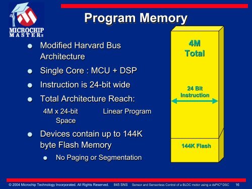
- Page 13 and 14: 16-bit Digital Signal Controller Ar
- Page 15: Operating Parameters Operating Spe
- Page 19 and 20: W Registers General Purpose Data Re
- Page 21 and 22: Interrupt Vector Table (IVT) Altern
- Page 23 and 24: System Management Features © 2004
- Page 25 and 26: Clock sources Low Pwr RC 512KHz Fas
- Page 27 and 28: LAB 1 Getting Started with the ds
- Page 29 and 30: Training board - Top dsPIC30F2010 P
- Page 31 and 32: Jumper J15 Jumpers and LEDs dsPIC30
- Page 33 and 34: Instructions for Lab1: Contd
- Page 35 and 36: Lab1 Results This same procedure ha
- Page 37 and 38: dsPIC 10-bit A/D Converter Feature
- Page 39 and 40: 10-bit A/D Converter A/D Configura
- Page 41 and 42: 10-bit A/D Converter A/D Conversio
- Page 43 and 44: 10-bit A/D Converter A/D Sampling
- Page 45 and 46: 10-bit A/D Converter ADCON3 Regist
- Page 47 and 48: Lab2 - Single channel ADC Conversio
- Page 49 and 50: Lab2 - Single channel ADC Conversio
- Page 51 and 52: Lab 2 Results Configuration of 10
- Page 53 and 54: 10-bit A/D Converter ADCHS - CH1,
- Page 55 and 56: Motor Control PWM Features Overvie
- Page 57 and 58: Motor Control PWM PTCON register
- Page 59 and 60: Motor Control PWM Center Aligned P
- Page 61 and 62: Motor Control PWM Duty Cycle Compa
- Page 63 and 64: Motor Control PWM Complementary ou
- Page 65 and 66: Motor Control PWM Dead Time Genera
- Page 67 and 68:
Motor Control PWM DTCON1 selects d
- Page 69 and 70:
Motor Control PWM FLTACON Register
- Page 71 and 72:
Lab 3 Objectives 3 MC PWM pairs ar
- Page 73 and 74:
Lab3 Jumper settings J2(2 pin) - s
- Page 75 and 76:
Lab 3: Lab3 Setup Part 1: Setup AD
- Page 77 and 78:
Lab 3 Setup (contd.) Lab 3 General
- Page 79 and 80:
Lab 3 Results Learned how to set
- Page 81 and 82:
Standard BLDC Control HALL A Red Wi
- Page 83 and 84:
Standard BLDC Position Sensing HALL
- Page 85 and 86:
Control of Sensored BLDC Simple Co
- Page 87 and 88:
CN Hardware Hall A CN4 100 A N 101
- Page 89 and 90:
Motor Control PWM OVDCON (override
- Page 91 and 92:
Lab4 Jumper settings J2(2 pin) - s
- Page 93 and 94:
Lab 4: Lab 4: Sensored Control (co
- Page 95 and 96:
Lab 4: Lab 4: Sensored BLDC (contd
- Page 97 and 98:
Sensorless BLDC Motor © 2004 Micro
- Page 99 and 100:
BLDC Sensorless Techniques Many
- Page 101 and 102:
BLDC Motor Back EMF DC- C DC+ A Bac
- Page 103 and 104:
Technique to Monitor Back EMF • B
- Page 105 and 106:
BEMF vs. Hall sensors Back EMF Hall
- Page 107 and 108:
Standard BLDC Position Sensing HALL
- Page 109 and 110:
Back EMF Crossing Diagram 0 0 0 SEC
- Page 111 and 112:
Lock Position 1 Time Starting Alg
- Page 113 and 114:
Starting Algorithm Parameters used
- Page 115 and 116:
Lab 5: Lab 5: Spinning a Sensorl
- Page 117 and 118:
Summary BLDC motor basics dsP
- Page 119 and 120:
Sensorless BLDC Issues Phase windi
- Page 121 and 122:
Phase Advance The 30 electrical