Motor Control PWM
Motor Control PWM
Motor Control PWM

Create successful ePaper yourself
Turn your PDF publications into a flip-book with our unique Google optimized e-Paper software.
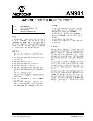
845 SNS<br />
Sensor and Sensorless <strong>Control</strong> of a<br />
BLDC <strong>Motor</strong> Using a dsPIC ® DSC<br />
Hands-on Class<br />
© 2004 Microchip Technology Incorporated. All Rights Reserved. 845 SNS Sensor and Sensorless <strong>Control</strong> of a BLDC motor using a dsPIC ® DSC 1
Agenda<br />
BLDC <strong>Motor</strong> Basics<br />
dsPIC ® DSC Peripherals for BLDC control - <strong>PWM</strong> and ADC<br />
<br />
<br />
<br />
lab 1 - “How to get started” by blinking an LED<br />
lab 2 - using the ADC<br />
lab 3 - using the <strong>PWM</strong> and multiple ADC channels<br />
<strong>Control</strong> of a BLDC motor with Position Sensors<br />
<br />
Lab 4 - Spinning a Sensored BLDC <strong>Motor</strong><br />
Review of BLDC Sensorless Techniques<br />
The Back EMF “zero crossing” technique<br />
Implementation on the dsPIC ® DSC (AN901)<br />
Commutation and other control loops<br />
<br />
Lab 5 - Setting Up and Tuning the Sensorless BLDC Reference<br />
Design<br />
© 2004 Microchip Technology Incorporated. All Rights Reserved. 845 SNS Sensor and Sensorless <strong>Control</strong> of a BLDC motor using a dsPIC ® DSC 2
Learning Objectives<br />
<br />
<br />
<br />
<br />
dsPIC ® DSC Peripherals used for BLDC<br />
<strong>Control</strong>:<br />
<br />
<br />
10-bit ADC<br />
<strong>Motor</strong> <strong>Control</strong> <strong>PWM</strong><br />
BLDC Basics<br />
BLDC <strong>Control</strong> Techniques<br />
<br />
<br />
Sensored Techniques<br />
Sensorless Techniques<br />
Write Code to Spin a Sensored and<br />
Sensorless BLDC <strong>Motor</strong><br />
© 2004 Microchip Technology Incorporated. All Rights Reserved. 845 SNS Sensor and Sensorless <strong>Control</strong> of a BLDC motor using a dsPIC ® DSC 3
BLDC <strong>Motor</strong> Basics<br />
© 2004 Microchip Technology Incorporated. All Rights Reserved. 845 SNS Sensor and Sensorless <strong>Control</strong> of a BLDC motor using a dsPIC ® DSC 4
The BrushLess DC (BLDC) <strong>Motor</strong><br />
<br />
<br />
<br />
<br />
<br />
An inside out brushed DC motor with<br />
electronic commutation<br />
A modern, much improved, version of the<br />
traditional brushed DC motor.<br />
Field, which has relatively low loss, is<br />
generated on the rotor using permanent<br />
magnets.<br />
Armature, which causes the majority of the<br />
loss, is on the stator which has good<br />
cooling.<br />
The Back EMF is usually somewhere<br />
between being sinusoidal and trapezoidal.<br />
© 2004 Microchip Technology Incorporated. All Rights Reserved. 845 SNS Sensor and Sensorless <strong>Control</strong> of a BLDC motor using a dsPIC ® DSC 5
Brushed & Brushless DC <strong>Motor</strong><br />
Construction<br />
PERMANENT MAGNET BRUSHED DC<br />
MOTOR<br />
PERMANENT MAGNET BRUSHLESS<br />
DC MOTOR<br />
© 2004 Microchip Technology Incorporated. All Rights Reserved. 845 SNS Sensor and Sensorless <strong>Control</strong> of a BLDC motor using a dsPIC ® DSC 6
BLDC Advantages Over Brushed<br />
DC <strong>Motor</strong><br />
<br />
<br />
<br />
<br />
<br />
<br />
Smaller size for same power owing, mainly,<br />
to the improved cooling of the armature.<br />
Operation to higher speeds.<br />
Lower inertia as no commutator or rotor<br />
windings.<br />
Therefore much higher acceleration rates<br />
possible.<br />
No brushes to maintain.<br />
No sparking on Commutator.<br />
© 2004 Microchip Technology Incorporated. All Rights Reserved. 845 SNS Sensor and Sensorless <strong>Control</strong> of a BLDC motor using a dsPIC ® DSC 7
BLDC <strong>Control</strong><br />
<br />
<br />
<br />
<br />
Mechanical commutator of brushed motor replaced<br />
by electronic switching of the phases.<br />
Switching must be correctly synchronised to<br />
absolute rotor position to ensure smooth and<br />
efficient torque production.<br />
The BLDC is a synchronous motor with no<br />
damping or starting windings.<br />
All discussions will focus on Y connected 3 phase<br />
motors with 3 leg inverters and square wave (120°)<br />
conduction.<br />
© 2004 Microchip Technology Incorporated. All Rights Reserved. 845 SNS Sensor and Sensorless <strong>Control</strong> of a BLDC motor using a dsPIC ® DSC 8
Standard BLDC Position Sensing<br />
<br />
<br />
<br />
A sensing disk is attached to the rotor which<br />
provides a ˜ 50% duty pattern aligned to the<br />
rotor magnets. The repetition rate of the<br />
pattern will follow the number of rotor poles.<br />
The disk is monitored by three optical or hall<br />
sensors, displaced by the equivalent of<br />
120°, , located on the stator.<br />
In the case of hall sensors, the rotor<br />
magnets themselves may be sensed<br />
directly.<br />
© 2004 Microchip Technology Incorporated. All Rights Reserved. 845 SNS Sensor and Sensorless <strong>Control</strong> of a BLDC motor using a dsPIC ® DSC 9
Brushless DC <strong>Motor</strong> Construction<br />
100<br />
R<br />
R<br />
N<br />
101 b<br />
com<br />
y<br />
001<br />
S<br />
Y<br />
N<br />
S<br />
r<br />
com<br />
r<br />
S 110<br />
N<br />
N<br />
S<br />
N<br />
y<br />
B<br />
b 010<br />
B<br />
6<br />
b<br />
4<br />
r<br />
com<br />
2<br />
5<br />
1<br />
3<br />
y<br />
Y<br />
S<br />
com<br />
011<br />
© 2004 Microchip Technology Incorporated. All Rights Reserved. 845 SNS Sensor and Sensorless <strong>Control</strong> of a BLDC motor using a dsPIC ® DSC 10
Standard Sensored BLDC<br />
<strong>Control</strong><br />
The 3 logic signals are decoded to determine<br />
which windings should be energized.<br />
There are 6 valid states and 2 states that should<br />
never be seen (000, 111).<br />
Use Lookup table to drive the 3 windings, high or<br />
low or no-drive.<br />
The 6 different valid states directly translate to the<br />
6 different 60° electrical cycle sectors.<br />
The states should only transition by one at a time.<br />
Missing transitions or invalid states should be<br />
detected for robust operation.<br />
© 2004 Microchip Technology Incorporated. All Rights Reserved. 845 SNS Sensor and Sensorless <strong>Control</strong> of a BLDC motor using a dsPIC ® DSC 11
Standard BLDC <strong>Control</strong><br />
HALL A<br />
Red Winding<br />
60 o<br />
HALL B<br />
Q1<br />
Q2<br />
Q3<br />
Yellow Winding<br />
HALL C<br />
Q4<br />
R Y B<br />
Q5 Q6<br />
Blue Winding<br />
+TORQUE FIRING<br />
Q3,Q5<br />
Q1,Q5 Q1,Q6 Q2,Q6 Q2,Q4 Q3,Q4 Q3,Q5<br />
Q1,Q5<br />
Q1,Q6<br />
Sector 5<br />
0 1 2<br />
3<br />
4<br />
5<br />
0<br />
1<br />
Hall States<br />
5 4 6 2<br />
3<br />
1<br />
5<br />
4<br />
6<br />
© 2004 Microchip Technology Incorporated. All Rights Reserved. 845 SNS Sensor and Sensorless <strong>Control</strong> of a BLDC motor using a dsPIC ® DSC 12
16-bit Digital Signal <strong>Control</strong>ler<br />
Architecture<br />
© 2004 Microchip Technology Incorporated. All Rights Reserved. 845 SNS Sensor and Sensorless <strong>Control</strong> of a BLDC motor using a dsPIC ® DSC 13
dsPIC30F <strong>Control</strong>ler Family<br />
Flash Program Memory:<br />
12 K - 144 K Bytes<br />
RAM<br />
512 - 8 K bytes<br />
Data EEPROM<br />
1K - 4K Bytes<br />
Pin-count<br />
18 - 80 pins<br />
Timers 16-bit Up to 5<br />
Input Capture Up to 8<br />
Output Compare / <strong>PWM</strong><br />
Up to 8 (individual time bases)<br />
<strong>Motor</strong> <strong>Control</strong> <strong>PWM</strong><br />
6 or 8 with shutdown pins<br />
A/D converter<br />
10-bit, 500 KSPS, up to 16 ch<br />
A/D converter<br />
12-bit, 100 KSPS, up to 16 ch<br />
UART 1 - 2<br />
SPI (8/16-bit) 1 - 2<br />
I 2 C 1<br />
QEI 1<br />
CODEC interface 1<br />
CAN 1 - 2<br />
© 2004 Microchip Technology Incorporated. All Rights Reserved. 845 SNS Sensor and Sensorless <strong>Control</strong> of a BLDC motor using a dsPIC ® DSC 14
Operating Parameters<br />
<br />
Operating Speed @ 5V (-40ºC to 85ºC) : 30 MIPS<br />
<br />
VDD: 2.5 to 5.5V<br />
<br />
Temp:<br />
-40º C to 125º C<br />
<br />
Program Memory:<br />
Flash<br />
<br />
Data Memory:<br />
SRAM, EEPROM<br />
<br />
Analog:<br />
10-bit & 12-bit Precision<br />
<br />
Package sizes<br />
<br />
<br />
<br />
<br />
18-pin SO & SP<br />
28-pin SO, SP and QFN<br />
40-pin SP; 44-pin TQFP<br />
64- and 80-pin TQFP<br />
DS<br />
© 2004 Microchip Technology Incorporated. All Rights Reserved. 845 SNS Sensor and Sensorless <strong>Control</strong> of a BLDC motor using a dsPIC ® DSC 15
Program Memory<br />
<br />
<br />
<br />
<br />
<br />
Modified Harvard Bus<br />
Architecture<br />
Single Core : MCU + DSP<br />
Instruction is 24-bit wide<br />
Total Architecture Reach:<br />
4M x 24-bit<br />
Linear Program<br />
Space<br />
Devices contain up to 144K<br />
byte Flash Memory<br />
<br />
No Paging or Segmentation<br />
4M<br />
Total<br />
24 Bit<br />
Instruction<br />
144K Flash<br />
© 2004 Microchip Technology Incorporated. All Rights Reserved. 845 SNS Sensor and Sensorless <strong>Control</strong> of a BLDC motor using a dsPIC ® DSC 16
Data EEPROM Memory<br />
<br />
<br />
<br />
<br />
<br />
<br />
Up to 4K bytes Data EE Memory<br />
Run-Time programmable<br />
Row and Word erasable<br />
Row and Word programmable<br />
Modify a Row of 16 words in 2 milliseconds<br />
Can access Data EEPROM for 16-bit data read<br />
operations<br />
MOV [++w4], [w6++]<br />
Data EE Memory used as source address for data read operation<br />
© 2004 Microchip Technology Incorporated. All Rights Reserved. 845 SNS Sensor and Sensorless <strong>Control</strong> of a BLDC motor using a dsPIC ® DSC 17
Data Memory<br />
<br />
<br />
<br />
<br />
Data is 16-bit wide<br />
<br />
Byte addressable<br />
Total Space:<br />
64K Bytes Linear Data Space<br />
<br />
No Banking<br />
Devices contain up to 8K Byte<br />
User RAM<br />
64K<br />
Total<br />
16 Bit Data<br />
Addressable Indirectly or with<br />
8K RAM<br />
Memory Direct ‘MOV’ ’ Instruction © 2004 Microchip Technology Incorporated. All Rights Reserved. 845 SNS Sensor and Sensorless <strong>Control</strong> of a BLDC motor using a dsPIC ® DSC 18
W Registers<br />
General Purpose<br />
Data Registers<br />
or<br />
Address Pointers<br />
Programmers Model<br />
W0<br />
W1<br />
W2<br />
W3<br />
W4<br />
W5<br />
W6<br />
W7<br />
W8<br />
W9<br />
W10<br />
W11<br />
W12<br />
W13<br />
W14<br />
W15<br />
15 0<br />
Divide Quotient<br />
Divide Remainder<br />
Frame Pointer<br />
Stack Pointer 0<br />
15 0<br />
Stack Pointer Limit<br />
SPLIM<br />
DSP OPERAND<br />
Registers<br />
DSP ADDRESS<br />
Registers<br />
DSP Accumulators<br />
(40-bit)<br />
ACCA<br />
ACCB<br />
39<br />
32<br />
31<br />
16<br />
15<br />
0<br />
OA OB SA SB OAB SAB DA DC IPL2IPL1 IPL0<br />
RA<br />
N<br />
OV<br />
Z<br />
C<br />
Status Register<br />
© 2004 Microchip Technology Incorporated. All Rights Reserved. 845 SNS Sensor and Sensorless <strong>Control</strong> of a BLDC motor using a dsPIC ® DSC 19
Interrupt Subsystem<br />
© 2004 Microchip Technology Incorporated. All Rights Reserved. 845 SNS Sensor and Sensorless <strong>Control</strong> of a BLDC motor using a dsPIC ® DSC 20
Interrupt Vector<br />
Table (IVT)<br />
Alternate<br />
Interrupt Vector<br />
Table (AIVT)<br />
Interrupt Vector Table<br />
Reset - GOTO Instruction<br />
Reset - GOTO Address<br />
Reserved<br />
Oscillator Fail Trap<br />
Address Error Trap<br />
Stack Error Trap<br />
Math Error Trap<br />
Reserved<br />
Reserved<br />
Reserved<br />
Interrupt Vector 0<br />
Interrupt Vector 1<br />
Interrupt Vector 2<br />
•<br />
•<br />
Interrupt Vector 53<br />
Reserved<br />
Reserved<br />
Reserved<br />
Oscillator Fail Trap<br />
•<br />
•<br />
•<br />
•<br />
Interrupt Vector 53<br />
0x000000<br />
0x000004<br />
0x00007E<br />
0x000084<br />
0x0000FE<br />
Decreasing Natural Order Priority<br />
© 2004 Microchip Technology Incorporated. All Rights Reserved. 845 SNS Sensor and Sensorless <strong>Control</strong> of a BLDC motor using a dsPIC ® DSC 21
Traps for Robust Operation<br />
Oscillator Failure Trap (level 14)<br />
Address Error Trap (level 13)<br />
<br />
<br />
<br />
Instruction fetch from illegal program space<br />
Data fetch from unimplemented data space<br />
Unaligned word access from data space<br />
Stack Error Trap (level 12)<br />
<br />
Stack overflow or underflow<br />
Arithmetic Error Trap (level 11)<br />
<br />
Divide by Zero<br />
Unsaturated Accumulator Overflow (A or B)<br />
<br />
<br />
Catastrophic Accumulator Overflow (either)<br />
Accumulator Shift Overflow<br />
© 2004 Microchip Technology Incorporated. All Rights Reserved. 845 SNS Sensor and Sensorless <strong>Control</strong> of a BLDC motor using a dsPIC ® DSC 22
System Management Features<br />
© 2004 Microchip Technology Incorporated. All Rights Reserved. 845 SNS Sensor and Sensorless <strong>Control</strong> of a BLDC motor using a dsPIC ® DSC 23
System Management<br />
Features<br />
dsPIC ® DSC has the same system management<br />
features that PIC ® MCU users love<br />
♥ Configurable Watchdog Timer with its own RC oscillator<br />
Programmable Time out: 2 ms - 16 sec<br />
♥ Power-On-Reset with a programmable delay 0, 4, 16, 64<br />
ms<br />
♥ Brown-out Reset with programmable levels<br />
♥ Low VDDV<br />
Detect Interrupt with programmable levels<br />
© 2004 Microchip Technology Incorporated. All Rights Reserved. 845 SNS Sensor and Sensorless <strong>Control</strong> of a BLDC motor using a dsPIC ® DSC 24
Clock sources<br />
Low Pwr RC 512KHz<br />
Fast RC 8.0 MHz<br />
OSCI<br />
EC Clock<br />
XTL, XT, HS<br />
Primary<br />
Xtal OSC<br />
PLL<br />
4x,<br />
8x,<br />
16x<br />
or bypass<br />
Clock Divide<br />
By<br />
1, 4, 16, 64<br />
System<br />
Clock<br />
OSCO<br />
SOSCI<br />
SOSCO<br />
32KHz<br />
Timer1 Xtal<br />
OSC<br />
Primary Oscillator for Crystals<br />
<br />
32 kHz for Real Time Clock<br />
<br />
<br />
Includes 2 Internal RC Oscillators<br />
PLL multiplies oscillator source<br />
for high frequency operation<br />
Clock divide can optionally slow clock<br />
to conserve power<br />
© 2004 Microchip Technology Incorporated. All Rights Reserved. 845 SNS Sensor and Sensorless <strong>Control</strong> of a BLDC motor using a dsPIC ® DSC 25
Fail-Safe Operation<br />
<br />
Features that make the target system safe!<br />
<br />
<br />
<br />
Clock monitor detects oscillator failure<br />
<br />
Automatic switch to an internal RC clock<br />
Illegal Program Instruction<br />
<br />
Device Resets<br />
Traps let software handle error conditions<br />
<br />
<br />
<br />
<br />
Oscillator Fail<br />
Address out of range<br />
Stack out of range<br />
Math errors<br />
© 2004 Microchip Technology Incorporated. All Rights Reserved. 845 SNS Sensor and Sensorless <strong>Control</strong> of a BLDC motor using a dsPIC ® DSC 26
LAB 1<br />
<br />
<br />
Getting Started with the dsPIC ® DSC BLDC<br />
board<br />
Objectives for Lab:<br />
<br />
<br />
<br />
<br />
<br />
Configure board hardware connections<br />
Open a workspace in MPLAB ® IDE<br />
Compile or Build the project in MPLAB IDE<br />
Follow procedure to Program the dsPIC DSC<br />
using ICD 2<br />
Follow procedure to Run the program using<br />
ICD 2<br />
© 2004 Microchip Technology Incorporated. All Rights Reserved. 845 SNS Sensor and Sensorless <strong>Control</strong> of a BLDC motor using a dsPIC ® DSC 27
You should have….<br />
1) MPLAB ® IDE V6.5 or higher installed<br />
2) Complete MPLAB ® ICD 2 setup<br />
3) BLDC motor control board(05-60001)<br />
4) 24V power supply for the above board<br />
5) Hurst(NTDynamo) BLDC motor with<br />
<br />
<br />
Power cable (4 wires with white square connector) and<br />
Hall sensor cable (5 wires with 8-pin inline connector)<br />
6) Circuit schematic BLDC motor control board<br />
© 2004 Microchip Technology Incorporated. All Rights Reserved. 845 SNS Sensor and Sensorless <strong>Control</strong> of a BLDC motor using a dsPIC ® DSC 28
Training board - Top<br />
dsPIC30F2010<br />
Power<br />
Reset<br />
R60<br />
S2<br />
S3<br />
Led D1<br />
<strong>Motor</strong><br />
connector<br />
DIP Switches<br />
Serial connector<br />
ICD 2 connector<br />
© 2004 Microchip Technology Incorporated. All Rights Reserved. 845 SNS Sensor and Sensorless <strong>Control</strong> of a BLDC motor using a dsPIC ® DSC 29
Training board - Bottom<br />
Power<br />
MOSFETs<br />
© 2004 Microchip Technology Incorporated. All Rights Reserved. 845 SNS Sensor and Sensorless <strong>Control</strong> of a BLDC motor using a dsPIC ® DSC 30
Jumper<br />
J15<br />
Jumpers and LEDs<br />
dsPIC30f2010<br />
Jumper J2<br />
LEDs<br />
<strong>PWM</strong>0<br />
to<br />
<strong>PWM</strong>5<br />
Power LED<br />
D7<br />
LEDs<br />
D1<br />
D2<br />
D3<br />
Jumpers<br />
J7, J8, J11, J12, J13, J14<br />
© 2004 Microchip Technology Incorporated. All Rights Reserved. 845 SNS Sensor and Sensorless <strong>Control</strong> of a BLDC motor using a dsPIC ® DSC 31
Default Jumper settings<br />
<br />
J2(2 pin) - shorted.<br />
<br />
J15(3 pin) - shorted between pin 2 & 3<br />
(short link towards the crystal oscillator)<br />
<br />
J7, J11 and J13 - shorted between pin 3 & 2<br />
<br />
<br />
(short link away from ICD 2 connector)<br />
JP8, JP12, JP14, JP16 and JP17 keep open<br />
Keep Potentiometer REF(R14) and R60 in<br />
center position<br />
© 2004 Microchip Technology Incorporated. All Rights Reserved. 845 SNS Sensor and Sensorless <strong>Control</strong> of a BLDC motor using a dsPIC ® DSC 32
Instructions for Lab1:<br />
<br />
<br />
<br />
<br />
<br />
<br />
Contd ...<br />
Lab1<br />
Make sure the DIP switches are in the<br />
CLOSE position (not OPEN)<br />
Connect power to System<br />
Open MPLAB ® IDE by double clicking on<br />
icon<br />
Select “File -> Open Workspace”<br />
Browse to<br />
“C:\MASTERs\845\Lab1\Lab1.mcw”<br />
Select “Lab1.mcw” to open workspace<br />
© 2004 Microchip Technology Incorporated. All Rights Reserved. 845 SNS Sensor and Sensorless <strong>Control</strong> of a BLDC motor using a dsPIC ® DSC 33
Lab 1 (contd.)<br />
<br />
Instructions for Lab1 (contd):<br />
<br />
Select “Debugger -> Build All”<br />
IF NO errors then ...<br />
<br />
Select “Debugger -> Program” to program<br />
<br />
Move DIP switches to OPEN position<br />
<br />
Select “Debugger -> Run” and D1 should<br />
blink<br />
© 2004 Microchip Technology Incorporated. All Rights Reserved. 845 SNS Sensor and Sensorless <strong>Control</strong> of a BLDC motor using a dsPIC ® DSC 34
Lab1 Results<br />
This same procedure has to be followed for<br />
programming and running software:<br />
<br />
<br />
When programming, move DIPs to CLOSE<br />
position (not OPEN)<br />
When running, move DIPs in OPEN position<br />
<br />
Each Lab has a workspace in the<br />
appropriate folder already created<br />
<br />
Use the workspace for each lab<br />
If D1 is blinking, your system is functional -<br />
Congratulations!!!!<br />
© 2004 Microchip Technology Incorporated. All Rights Reserved. 845 SNS Sensor and Sensorless <strong>Control</strong> of a BLDC motor using a dsPIC ® DSC 35
10-bit A/D Converter<br />
© 2004 Microchip Technology Incorporated. All Rights Reserved. 845 SNS Sensor and Sensorless <strong>Control</strong> of a BLDC motor using a dsPIC ® DSC 36
dsPIC 10-bit A/D Converter<br />
<br />
Feature Summary<br />
<br />
<br />
<br />
<br />
<br />
<br />
<br />
10-bit Resolution with +/- 1 bit accuracy<br />
500K Samples/Sec conversion rate<br />
Up to 16 input channels, 4 S/H Amplifiers<br />
Unipolar differential measurements<br />
External VREF+ V<br />
+ and VREF-V<br />
Many sampling sequences can be<br />
programmed<br />
Multiple conversion trigger sources<br />
© 2004 Microchip Technology Incorporated. All Rights Reserved. 845 SNS Sensor and Sensorless <strong>Control</strong> of a BLDC motor using a dsPIC ® DSC 37
Input Muxes<br />
10-bit A/D Block Diagram<br />
VREF+<br />
VREF-<br />
Conversion<br />
<strong>Control</strong><br />
AN0<br />
AN1<br />
SH0<br />
SH1<br />
SH2<br />
A D C<br />
10 bit<br />
500 ksps<br />
16-word<br />
buffer<br />
Data<br />
Formatting<br />
Bus Interface<br />
AN15<br />
SH3<br />
Sample<br />
Sequence<br />
<strong>Control</strong><br />
© 2004 Microchip Technology Incorporated. All Rights Reserved. 845 SNS Sensor and Sensorless <strong>Control</strong> of a BLDC motor using a dsPIC ® DSC 38
10-bit A/D Converter<br />
<br />
A/D Configuration for Labs<br />
<br />
Lab 2 - Sample one channel, manual<br />
sampling, manual conversion<br />
Lab 3 - Simultaneously sample 4<br />
channels, auto sample, trigger<br />
conversion from <strong>PWM</strong><br />
<br />
Keep these configurations in mind as<br />
we look at the A/D control registers<br />
© 2004 Microchip Technology Incorporated. All Rights Reserved. 845 SNS Sensor and Sensorless <strong>Control</strong> of a BLDC motor using a dsPIC ® DSC 39
10-bit A/D Converter<br />
<br />
ADCON1 Register Bits<br />
<br />
<br />
<br />
<br />
<br />
<br />
<br />
<br />
DONE - A/D conversion status<br />
SAMP - A/D sampling status/control<br />
ASAM - Auto sample control bit<br />
SIMSAM - Simultaneous sample control<br />
SSRC - Conversion trigger source<br />
FORM - Result format<br />
ADSIDL - Stop in IDLE control bit<br />
ADON - A/D enable bit (set last)<br />
© 2004 Microchip Technology Incorporated. All Rights Reserved. 845 SNS Sensor and Sensorless <strong>Control</strong> of a BLDC motor using a dsPIC ® DSC 40
10-bit A/D Converter<br />
<br />
A/D Conversion Trigger Options<br />
<br />
<br />
<br />
<br />
<br />
Auto convert (internal counter)<br />
<strong>Motor</strong> <strong>Control</strong> <strong>PWM</strong> special event trigger<br />
<br />
allows synchronized shunt current<br />
measurement<br />
Timer3 period match event<br />
Edge input on I/O pin<br />
Manual trigger<br />
<br />
user clears SAMP bit to begin CONV<br />
© 2004 Microchip Technology Incorporated. All Rights Reserved. 845 SNS Sensor and Sensorless <strong>Control</strong> of a BLDC motor using a dsPIC ® DSC 41
10-bit A/D Converter<br />
<br />
ADCON2 Register Bits<br />
<br />
<br />
<br />
<br />
<br />
<br />
<br />
ALTS - Alternate MUX sample mode<br />
BUFM - Buffer mode control bit<br />
SMPI - Samples per interrupt<br />
BUFS - Buffer status<br />
CHPS - S/H Channels per Sample<br />
CSCNA - MUX A Scan enable bit<br />
VCFG - Voltage Ref configuration<br />
© 2004 Microchip Technology Incorporated. All Rights Reserved. 845 SNS Sensor and Sensorless <strong>Control</strong> of a BLDC motor using a dsPIC ® DSC 42
10-bit A/D Converter<br />
<br />
A/D Sampling Options<br />
<br />
<br />
<br />
<br />
<br />
<br />
1, 2, or 4 S/H amplifiers for conversions<br />
<br />
Simultaneous or sequentially sampled<br />
Scan mode with enable for each input<br />
Two multiplexer settings can be programmed<br />
<br />
Alternate between conversions<br />
Selectable number of samples per interrupt<br />
Selectable buffer fill mode<br />
Auto or manual sample<br />
© 2004 Microchip Technology Incorporated. All Rights Reserved. 845 SNS Sensor and Sensorless <strong>Control</strong> of a BLDC motor using a dsPIC ® DSC 43
Sampling Options<br />
AN0<br />
AN1<br />
AN2<br />
AN3<br />
SIMULTANEOUS<br />
SAMPLING<br />
SEQUENTIAL<br />
SAMPLING<br />
© 2004 Microchip Technology Incorporated. All Rights Reserved. 845 SNS Sensor and Sensorless <strong>Control</strong> of a BLDC motor using a dsPIC ® DSC 44
10-bit A/D Converter<br />
<br />
ADCON3 Register Bits<br />
<br />
<br />
<br />
ADCS - A/D Clock setting (Tad)<br />
<br />
Tcy/2 increments, 167ns min<br />
ADRC - A/D RC oscillator<br />
SAMC - Auto Sample Time bits<br />
© 2004 Microchip Technology Incorporated. All Rights Reserved. 845 SNS Sensor and Sensorless <strong>Control</strong> of a BLDC motor using a dsPIC ® DSC 45
10-bit A/D Converter<br />
<br />
<br />
ADPCFG Register<br />
<br />
Sets port pin for analog (default) or digital<br />
mode<br />
ADCSSL - A/D Input Scan Select Register<br />
<br />
Use when CSCNA bit set<br />
© 2004 Microchip Technology Incorporated. All Rights Reserved. 845 SNS Sensor and Sensorless <strong>Control</strong> of a BLDC motor using a dsPIC ® DSC 46
Lab2 - Single channel ADC<br />
Conversion<br />
Instructions for Lab2:<br />
<br />
<br />
….. Contd.<br />
Use workspace<br />
“C:\MASTERs\845\Lab2\Lab2.mcw”<br />
Write code to setup ADC:<br />
<br />
Convert single Pot REF on AN2(RB2)<br />
<br />
Use Manual Sample by setting SAMP bit<br />
every 100 mS (use Delay100 mS routine)<br />
<br />
Manually check conversion complete<br />
<br />
Use Internal RC for Tad<br />
© 2004 Microchip Technology Incorporated. All Rights Reserved. 845 SNS Sensor and Sensorless <strong>Control</strong> of a BLDC motor using a dsPIC ® DSC 47
Lab2 - Single channel ADC<br />
Conversion (contd.)<br />
<br />
Code to be modified clearly marked:<br />
“Replace text with Code”<br />
<br />
Compile the program using “Project -> Build<br />
All”<br />
If no errors then Program the part but ...<br />
<br />
MAKE SURE DIPs are in CLOSE position<br />
<br />
Use “Debugger -> Program” to program part<br />
<br />
MAKE SURE DIPs are in OPEN position<br />
Contd ...<br />
© 2004 Microchip Technology Incorporated. All Rights Reserved. 845 SNS Sensor and Sensorless <strong>Control</strong> of a BLDC motor using a dsPIC ® DSC 48
Lab2 - Single channel ADC<br />
Conversion (contd.)<br />
<br />
In Windows ® :<br />
<br />
Open Hyperterm “Lab2.ht” in Lab2<br />
directory.<br />
<br />
If Bottom Status reads “Disconnected” then<br />
connect by selecting: “Call -> Call”<br />
<br />
In MPLAB ® IDE, Run the program: “Debugger -<br />
> RUN”<br />
<br />
Turn POT REF to view different values in<br />
Hyperterm.<br />
© 2004 Microchip Technology Incorporated. All Rights Reserved. 845 SNS Sensor and Sensorless <strong>Control</strong> of a BLDC motor using a dsPIC ® DSC 49
Lab 2 Result<br />
© 2004 Microchip Technology Incorporated. All Rights Reserved. 845 SNS Sensor and Sensorless <strong>Control</strong> of a BLDC motor using a dsPIC ® DSC 50
Lab 2 Results<br />
<br />
<br />
Configuration of 10-bit ADC<br />
Serial communications using dsPIC ® DSC<br />
© 2004 Microchip Technology Incorporated. All Rights Reserved. 845 SNS Sensor and Sensorless <strong>Control</strong> of a BLDC motor using a dsPIC ® DSC 51
10-bit A/D Converter<br />
<br />
ADCHS Register - CH0 S/H Input Selection<br />
AN1<br />
AN0 - AN15<br />
+<br />
-<br />
CH 0<br />
ADCHS Register<br />
VREF-<br />
R/W-0 R/W-0 R/W-0 R/W-0 R/W-0 R/W-0 R/W-0 R/W-0<br />
CHXNB CHXSB CH0NB<br />
CH0SB<br />
bit15 14 13 12 11 10 9 bit8<br />
R/W-0 R/W-0 R/W-0 R/W-0 R/W-0 R/W-0 R/W-0 R/W-0<br />
CHXNA CHXSA CH0NA<br />
CH0SA<br />
bit7 6 5 4 3 2 1 bit0<br />
© 2004 Microchip Technology Incorporated. All Rights Reserved. 845 SNS Sensor and Sensorless <strong>Control</strong> of a BLDC motor using a dsPIC ® DSC 52
10-bit A/D Converter<br />
<br />
ADCHS - CH1, CH2, CH3 Input Select<br />
AN0<br />
AN3<br />
AN6<br />
+<br />
CH 1<br />
-<br />
AN1<br />
AN4<br />
AN7<br />
+<br />
CH 2<br />
-<br />
AN2<br />
AN5<br />
AN8<br />
+<br />
CH 3<br />
-<br />
AN9<br />
VREF-<br />
VREF-<br />
AN10<br />
AN11<br />
VREF-<br />
ADCHS Register<br />
R/W -0 R/W -0 R/W -0 R/W -0 R/W -0 R/W -0 R/W -0 R/W-0<br />
CHXNB CHXSB CH0NB<br />
CH0SB<br />
bit15 14 13 12 11 10 9 bit8<br />
R/W-0 R/W-0 R/W-0 R/W-0 R/W-0 R/W-0 R/W-0 R/W-0<br />
CHXNA CHXSA CH0NA<br />
CH0SA<br />
bit7 6 5 4 3 2 1 bit0<br />
© 2004 Microchip Technology Incorporated. All Rights Reserved. 845 SNS Sensor and Sensorless <strong>Control</strong> of a BLDC motor using a dsPIC ® DSC 53
<strong>Motor</strong> <strong>Control</strong> <strong>PWM</strong> Module<br />
© 2004 Microchip Technology Incorporated. All Rights Reserved. 845 SNS Sensor and Sensorless <strong>Control</strong> of a BLDC motor using a dsPIC ® DSC 54
<strong>Motor</strong> <strong>Control</strong> <strong>PWM</strong><br />
<br />
Features Overview<br />
<br />
<br />
<br />
<br />
<br />
<br />
<br />
Designed for ACIM, BLDC, SR, UPS<br />
Complementary <strong>PWM</strong> signals w/ dead time<br />
Independent output mode<br />
Special <strong>PWM</strong> generation modes<br />
Fault pins for protection of power circuits<br />
Override register for commutation applications<br />
Synchronized A/D conversions<br />
© 2004 Microchip Technology Incorporated. All Rights Reserved. 845 SNS Sensor and Sensorless <strong>Control</strong> of a BLDC motor using a dsPIC ® DSC 55
<strong>Motor</strong> <strong>Control</strong> <strong>PWM</strong><br />
15-bit Time-base<br />
Manual Override<br />
Duty Cycle<br />
Generator #4<br />
Dead Time Unit<br />
<strong>PWM</strong>4H<br />
<strong>PWM</strong>4L<br />
Duty Cycle<br />
Generator #3<br />
Duty Cycle<br />
Generator #2<br />
Dead Time Unit<br />
Dead Time Unit<br />
<strong>PWM</strong> Output<br />
<strong>Control</strong> Logic<br />
<strong>PWM</strong>3H<br />
<strong>PWM</strong>3L<br />
<strong>PWM</strong>2H<br />
<strong>PWM</strong>2L<br />
Four <strong>PWM</strong> output<br />
pairs with output<br />
polarity control<br />
Duty Cycle<br />
Generator #1<br />
Dead Time Unit<br />
<strong>PWM</strong>1H<br />
<strong>PWM</strong>1L<br />
A/D Conversion<br />
Trigger<br />
Fault A<br />
Fault B<br />
Two fault pins w/<br />
programmable fault<br />
states<br />
© 2004 Microchip Technology Incorporated. All Rights Reserved. 845 SNS Sensor and Sensorless <strong>Control</strong> of a BLDC motor using a dsPIC ® DSC 56
<strong>Motor</strong> <strong>Control</strong> <strong>PWM</strong><br />
<br />
PTCON register<br />
<br />
<br />
<br />
<br />
<br />
PTMOD - Timebase Mode<br />
PTCKPS - Timebase clock pre-scale<br />
PTOPS - Timebase interrupt post-scale<br />
PTSIDL - Stop in IDLE mode<br />
PTEN - Timebase Enable<br />
R/W-0 U-0 R/W-0 U-0 U-0 U-0 U-0 U-0<br />
PTEN - PTSIDL -<br />
-<br />
-<br />
- -<br />
bit15 14 13 12 11 10 9 bit8<br />
R/W-0 R/W-0 R/W-0 R/W-0 R/W-0 R/W-0 R/W-0 R/W-0<br />
PTOPS<br />
PTCKPS PTMOD<br />
bit7 6 5 4 3 2 1 bit0<br />
© 2004 Microchip Technology Incorporated. All Rights Reserved. 845 SNS Sensor and Sensorless <strong>Control</strong> of a BLDC motor using a dsPIC ® DSC 57
<strong>Motor</strong> <strong>Control</strong> <strong>PWM</strong><br />
<br />
Edge Aligned <strong>PWM</strong><br />
PTPER<br />
PDC3<br />
PDC2<br />
PDC1<br />
<strong>PWM</strong>1<br />
<strong>PWM</strong>2<br />
<strong>PWM</strong>3<br />
© 2004 Microchip Technology Incorporated. All Rights Reserved. 845 SNS Sensor and Sensorless <strong>Control</strong> of a BLDC motor using a dsPIC ® DSC 58
<strong>Motor</strong> <strong>Control</strong> <strong>PWM</strong><br />
<br />
Center Aligned <strong>PWM</strong><br />
buffer<br />
update<br />
duty<br />
cycle<br />
changed<br />
buffer<br />
update<br />
PTPER<br />
PDCx<br />
<strong>PWM</strong><br />
We will use center aligned <strong>PWM</strong> for today’s labs.<br />
© 2004 Microchip Technology Incorporated. All Rights Reserved. 845 SNS Sensor and Sensorless <strong>Control</strong> of a BLDC motor using a dsPIC ® DSC 59
<strong>Motor</strong> <strong>Control</strong> <strong>PWM</strong><br />
<br />
<strong>PWM</strong> Frequency and Counting Resolution<br />
<br />
<br />
<br />
<br />
<br />
<br />
<br />
The 15-bit PTMR increments every Tcy<br />
PTPER sets the counting period in Tcy<br />
16-bit duty cycles allow Tcy/2 edge resolution<br />
Upper 15 bits of d.c. compared to PTMR<br />
LSbit of duty cycle specifies Tcy/2 boundary<br />
Divide count period value by 2 to get PTPER<br />
<strong>PWM</strong> frequency is halved for center-aligned<br />
© 2004 Microchip Technology Incorporated. All Rights Reserved. 845 SNS Sensor and Sensorless <strong>Control</strong> of a BLDC motor using a dsPIC ® DSC 60
<strong>Motor</strong> <strong>Control</strong> <strong>PWM</strong><br />
<br />
Duty Cycle Comparison Block Diagram<br />
15<br />
PDCx<br />
1<br />
16-bit Compare<br />
PTDIR<br />
15<br />
14<br />
PTMR<br />
0<br />
Tcy<br />
D<br />
Tcy/2<br />
© 2004 Microchip Technology Incorporated. All Rights Reserved. 845 SNS Sensor and Sensorless <strong>Control</strong> of a BLDC motor using a dsPIC ® DSC 61
<strong>Motor</strong> <strong>Control</strong> <strong>PWM</strong><br />
<br />
<strong>PWM</strong> Formula for Center Aligned <strong>PWM</strong><br />
PTPER = (Fcy/Fpwm - 1)/2<br />
<br />
<strong>PWM</strong> Formula for Edge Aligned <strong>PWM</strong><br />
PTPER = (Fcy/Fpwm - 1)<br />
© 2004 Microchip Technology Incorporated. All Rights Reserved. 845 SNS Sensor and Sensorless <strong>Control</strong> of a BLDC motor using a dsPIC ® DSC 62
<strong>Motor</strong> <strong>Control</strong> <strong>PWM</strong><br />
<br />
Complementary output mode<br />
+V<br />
1H<br />
2H<br />
3H<br />
3 Phase<br />
BLDC or<br />
ACIM<br />
1L<br />
2L<br />
3L<br />
V DD<br />
<strong>PWM</strong> Generator<br />
<strong>PWM</strong>xH<br />
Dead Band<br />
<strong>PWM</strong>xL<br />
© 2004 Microchip Technology Incorporated. All Rights Reserved. 845 SNS Sensor and Sensorless <strong>Control</strong> of a BLDC motor using a dsPIC ® DSC 63
<strong>Motor</strong> <strong>Control</strong> <strong>PWM</strong><br />
<br />
<strong>PWM</strong>CON1 register<br />
<br />
<br />
<strong>PWM</strong> output enable bits<br />
<strong>PWM</strong> output mode select<br />
<br />
For labs, enable <strong>PWM</strong>1, <strong>PWM</strong>2, and <strong>PWM</strong>3<br />
pairs for complementary mode<br />
U-0 U-0 U-0 U-0 R/W-0 R/W-0 R/W-0 R/W-0<br />
-<br />
-<br />
-<br />
- PMOD4 PMOD3 PMOD2 PMOD1<br />
bit15 14 13 12 11 10 9 bit8<br />
R/W-0 R/W-0 R/W-0 R/W-0 R/W-0 R/W-0 R/W-0 R/W-0<br />
PEN4H PEN3H PEN2H PEN1H PEN4L PEN3L PEN2L PEN1L<br />
bit7 6 5 4 3 2 1 bit0<br />
© 2004 Microchip Technology Incorporated. All Rights Reserved. 845 SNS Sensor and Sensorless <strong>Control</strong> of a BLDC motor using a dsPIC ® DSC 64
<strong>Motor</strong> <strong>Control</strong> <strong>PWM</strong><br />
<br />
Dead Time Generators<br />
<br />
<br />
<br />
<br />
<br />
Two programmable dead times<br />
<br />
one for dsPIC2010<br />
<strong>Control</strong> bits choose dead time for<br />
active/inactive events<br />
Two ways to use DTA and DTB<br />
Tcy minimum resolution<br />
Prescalers for increased dead time range<br />
© 2004 Microchip Technology Incorporated. All Rights Reserved. 845 SNS Sensor and Sensorless <strong>Control</strong> of a BLDC motor using a dsPIC ® DSC 65
MC<strong>PWM</strong> Dead Time Insertion<br />
<br />
<br />
<br />
<br />
<br />
Applies only to pin pairs in complimentary mode<br />
Two programmable dead times<br />
One dead time per pair for multiple inverters OR<br />
Two dead times per pair for distortion optimization<br />
T cy minimum resolution with four pre-scale options<br />
T cy<br />
Dead Time A<br />
Dead Time B<br />
<strong>PWM</strong>1H<br />
<strong>PWM</strong>1H<br />
<strong>PWM</strong>1L<br />
<strong>PWM</strong>1L<br />
© 2004 Microchip Technology Incorporated. All Rights Reserved. 845 SNS Sensor and Sensorless <strong>Control</strong> of a BLDC motor using a dsPIC ® DSC 66
<strong>Motor</strong> <strong>Control</strong> <strong>PWM</strong><br />
<br />
DTCON1 selects dead time value for A and B<br />
DTBPS1 DTBPS0<br />
DTB
MC<strong>PWM</strong> Fault Inputs<br />
<br />
<br />
<br />
<br />
<br />
<br />
<br />
<br />
Two programmable fault pins: Fault A, Fault B<br />
<br />
dsPIC2010 only has Fault A<br />
Fault pins can be assigned to each output pair<br />
Fault state for each output is programmable<br />
Automatic or latched fault protection<br />
Interrupt vector for each fault input<br />
Fault A has priority over Fault B<br />
Fault condition overrides all other pin control<br />
Fault pins can be used as interrupt pins when<br />
not used for <strong>PWM</strong> module<br />
© 2004 Microchip Technology Incorporated. All Rights Reserved. 845 SNS Sensor and Sensorless <strong>Control</strong> of a BLDC motor using a dsPIC ® DSC 68
<strong>Motor</strong> <strong>Control</strong> <strong>PWM</strong><br />
<br />
FLTACON Register<br />
<br />
<br />
<br />
FAENx - Enables pin pair for control by fault pin<br />
FLTAM - Latched or cycle-by-cycle mode<br />
FAOVxx - Override value bits<br />
<br />
<br />
FLTBCON register is identical<br />
For labs - FLTA drives all outputs inactive, latched<br />
mode<br />
FAOV4H FAOV4L FAOV3H FAOV3L FAOV2H FAOV2L FAOV1H FAOV1L<br />
bit15 14 13 12 11 10 9 bit8<br />
FLTAM -<br />
-<br />
- FAEN4 FAEN3 FAEN2 FAEN1<br />
bit7 6 5 4 3 2 1 bit0<br />
© 2004 Microchip Technology Incorporated. All Rights Reserved. 845 SNS Sensor and Sensorless <strong>Control</strong> of a BLDC motor using a dsPIC ® DSC 69
MC<strong>PWM</strong> A/D Synchronization<br />
SEVTCMP register sets A/D conversion start time in <strong>PWM</strong><br />
cycle<br />
Ensure A/D properly captures shunt current<br />
Can also use to minimize control loop update delay<br />
Trigger conversion at end of bottom transistor on-time<br />
<strong>PWM</strong>1H<br />
<strong>PWM</strong>1H<br />
<strong>PWM</strong>1L<br />
T<br />
<strong>PWM</strong>1L<br />
To A/D<br />
© 2004 Microchip Technology Incorporated. All Rights Reserved. 845 SNS Sensor and Sensorless <strong>Control</strong> of a BLDC motor using a dsPIC ® DSC 70
Lab 3 Objectives<br />
<br />
3 MC <strong>PWM</strong> pairs are connected to 3 ADC<br />
inputs<br />
MC <strong>PWM</strong>s will be driven with a 25%, 50%<br />
and 75% duty cycle<br />
<br />
The average of the duty cycle will be<br />
measured by each ADC<br />
<br />
If the configuration is correct then the 3 ADC<br />
value displayed will be 1.8V, 2.8V and 3.75V<br />
using Hyperterm<br />
© 2004 Microchip Technology Incorporated. All Rights Reserved. 845 SNS Sensor and Sensorless <strong>Control</strong> of a BLDC motor using a dsPIC ® DSC 71
Lab 3 Hardware<br />
+V<br />
1H<br />
2H<br />
3H<br />
<strong>PWM</strong>3<br />
AN5<br />
1L<br />
2L<br />
3L<br />
<strong>PWM</strong>2<br />
AN4<br />
<strong>PWM</strong>1<br />
AN3<br />
© 2004 Microchip Technology Incorporated. All Rights Reserved. 845 SNS Sensor and Sensorless <strong>Control</strong> of a BLDC motor using a dsPIC ® DSC 72
Lab3 Jumper settings<br />
<br />
J2(2 pin) - shorted.<br />
<br />
J15(3 pin) - shorted between pin 2 & 3<br />
(short link towards the crystal oscillator)<br />
<br />
J7, J11 and J13 - shorted between pin 2 & 3<br />
<br />
<br />
(short link away from ICD 2 connector)<br />
JP8, JP12, JP14, JP16 and JP17 keep open<br />
Keep Potentiometer REF(R14) and R60 in<br />
center position<br />
© 2004 Microchip Technology Incorporated. All Rights Reserved. 845 SNS Sensor and Sensorless <strong>Control</strong> of a BLDC motor using a dsPIC ® DSC 73
Lab 3 Objectives<br />
<br />
<br />
Learn to setup the MC <strong>PWM</strong> period, duty<br />
cycle, dead time, ADC trigger etc.<br />
Learn to setup the ADC for simultaneous<br />
sampling and conversion on multiple<br />
channels<br />
© 2004 Microchip Technology Incorporated. All Rights Reserved. 845 SNS Sensor and Sensorless <strong>Control</strong> of a BLDC motor using a dsPIC ® DSC 74
Lab 3:<br />
<br />
Lab3 Setup<br />
Part 1: Setup ADC<br />
<br />
ADC to simultaneously sample 4 channels<br />
Set CH0 - AN2(Pot), CH1 - AN3, CH2 -<br />
AN4 and CH3 - AN5. Vref- = GND<br />
<br />
Trigger Conversion with 16 <strong>PWM</strong> Periods<br />
<br />
Set Tad = 4Tcy<br />
<br />
Modify Registers ADCON1, ADCON2,<br />
ADCON3, ADCHS and ADPCFG<br />
<br />
Code to be modified is clearly marked<br />
© 2004 Microchip Technology Incorporated. All Rights Reserved. 845 SNS Sensor and Sensorless <strong>Control</strong> of a BLDC motor using a dsPIC ® DSC 75
Lab3 :<br />
<br />
Lab 3 Setup (contd.)<br />
Part 2: setup MC <strong>PWM</strong><br />
<br />
Setup for continuous center aligned <strong>PWM</strong><br />
<br />
Complementary pairs<br />
<br />
Fcy = 20Mips , <strong>PWM</strong> Freq = 80khz<br />
PDC1 = 25%, PDC2 = 50% PDC3 = 75%<br />
<br />
Dead time = 1 uS (active and inactive)<br />
<br />
Code to be modified is clearly marked<br />
© 2004 Microchip Technology Incorporated. All Rights Reserved. 845 SNS Sensor and Sensorless <strong>Control</strong> of a BLDC motor using a dsPIC ® DSC 76
Lab 3 Setup (contd.)<br />
<br />
Lab 3 General:<br />
<br />
<br />
<br />
<br />
<br />
Use workspace in:<br />
“C:\MASTERs\845\Lab3\Lab3.mcw”<br />
Do not connect the motor to the board<br />
Use Hyperterm setup: “Lab2.ht” in Lab3<br />
directory to view results of the ADC<br />
Make sure that DIPs are in CLOSE position<br />
when programming<br />
Make sure that DIPs are in OPEN position<br />
when running<br />
© 2004 Microchip Technology Incorporated. All Rights Reserved. 845 SNS Sensor and Sensorless <strong>Control</strong> of a BLDC motor using a dsPIC ® DSC 77
Lab3 Result<br />
© 2004 Microchip Technology Incorporated. All Rights Reserved. 845 SNS Sensor and Sensorless <strong>Control</strong> of a BLDC motor using a dsPIC ® DSC 78
Lab 3 Results<br />
<br />
<br />
<br />
Learned how to setup the ADC<br />
Learned how to setup the <strong>PWM</strong><br />
We should now have sufficient information<br />
to setup a simple sensored control of a<br />
BLDC motor<br />
© 2004 Microchip Technology Incorporated. All Rights Reserved. 845 SNS Sensor and Sensorless <strong>Control</strong> of a BLDC motor using a dsPIC ® DSC 79
Brushless DC <strong>Motor</strong> Construction<br />
100<br />
R<br />
R<br />
N<br />
101 b<br />
com<br />
y<br />
001<br />
S<br />
Y<br />
N<br />
S<br />
r<br />
com<br />
r<br />
S 110<br />
N<br />
N<br />
S<br />
N<br />
y<br />
B<br />
b 010<br />
B<br />
6<br />
b<br />
4<br />
r<br />
com<br />
2<br />
5<br />
1<br />
3<br />
y<br />
Y<br />
S<br />
com<br />
011<br />
© 2004 Microchip Technology Incorporated. All Rights Reserved. 845 SNS Sensor and Sensorless <strong>Control</strong> of a BLDC motor using a dsPIC ® DSC 80
Standard BLDC <strong>Control</strong><br />
HALL A<br />
Red Winding<br />
60 o<br />
HALL B<br />
Q1<br />
Q2<br />
Q3<br />
Yellow Winding<br />
HALL C<br />
Q4<br />
R Y B<br />
Q5 Q6<br />
Blue Winding<br />
+TORQUE FIRING<br />
Q3,Q5<br />
Q1,Q5 Q1,Q6 Q2,Q6 Q2,Q4 Q3,Q4 Q3,Q5<br />
Q1,Q5<br />
Q1,Q6<br />
Sector 5<br />
0 1 2<br />
3<br />
4<br />
5<br />
0<br />
1<br />
Hall States<br />
5 4 6 2<br />
3<br />
1<br />
5<br />
4<br />
6<br />
© 2004 Microchip Technology Incorporated. All Rights Reserved. 845 SNS Sensor and Sensorless <strong>Control</strong> of a BLDC motor using a dsPIC ® DSC 81
Standard Sensored BLDC<br />
<strong>Control</strong><br />
The 3 logic signals are decoded to determine<br />
which windings should be energized.<br />
There are 6 valid states and 2 states that should<br />
never be seen (000, 111).<br />
Use Lookup table to drive the 3 windings, high or<br />
low or no-drive.<br />
The 6 different valid states directly translate to the<br />
6 different 60° electrical cycle sectors.<br />
The states should only transition by one at a time.<br />
Missing transitions or invalid states should be<br />
detected for robust operation.<br />
© 2004 Microchip Technology Incorporated. All Rights Reserved. 845 SNS Sensor and Sensorless <strong>Control</strong> of a BLDC motor using a dsPIC ® DSC 82
Standard BLDC Position Sensing<br />
HALL R<br />
60 o<br />
HALL Y<br />
HALL B<br />
SECTOR<br />
HALL STATE<br />
RYB<br />
5 0 1 2 3 4 5 0 1<br />
5 4 6 2 3 1 5 4 6<br />
© 2004 Microchip Technology Incorporated. All Rights Reserved. 845 SNS Sensor and Sensorless <strong>Control</strong> of a BLDC motor using a dsPIC ® DSC 83
BLDC <strong>Motor</strong> Construction<br />
Rotor magnets<br />
Stator winding<br />
Hall sensors<br />
© 2004 Microchip Technology Incorporated. All Rights Reserved. 845 SNS Sensor and Sensorless <strong>Control</strong> of a BLDC motor using a dsPIC ® DSC 84
<strong>Control</strong> of Sensored BLDC<br />
<br />
Simple <strong>Control</strong> Technique:<br />
<br />
<br />
<br />
<br />
Sense change in state of position<br />
Read Hall sensors to determine the new state<br />
Use lookup table for commutation<br />
Use <strong>PWM</strong> for speed control<br />
© 2004 Microchip Technology Incorporated. All Rights Reserved. 845 SNS Sensor and Sensorless <strong>Control</strong> of a BLDC motor using a dsPIC ® DSC 85
Change Notification (CN)<br />
<br />
dsPIC ® DSC has Change Notification inputs:<br />
<br />
<br />
<br />
Detect digital changes on a specific input pin<br />
and generates an interrupt<br />
Hall sensors A, B and C are connected to RB3,<br />
4 and 5 or CN4, 5 and 6 respectively.<br />
When CNxInterrupt occurs, all 3 Hall inputs are<br />
read and a lookup table is used to control the<br />
BLDC motor<br />
© 2004 Microchip Technology Incorporated. All Rights Reserved. 845 SNS Sensor and Sensorless <strong>Control</strong> of a BLDC motor using a dsPIC ® DSC 86
CN Hardware<br />
Hall A<br />
CN4<br />
100<br />
A<br />
N<br />
101<br />
c<br />
com<br />
a<br />
S 110<br />
N<br />
S<br />
N<br />
com<br />
b<br />
001<br />
S<br />
B<br />
N<br />
S<br />
a<br />
N<br />
c<br />
b<br />
C<br />
010<br />
Hall B<br />
CN5<br />
S<br />
com<br />
011<br />
Hall C<br />
CN6<br />
© 2004 Microchip Technology Incorporated. All Rights Reserved. 845 SNS Sensor and Sensorless <strong>Control</strong> of a BLDC motor using a dsPIC ® DSC 87
<strong>Motor</strong> <strong>Control</strong> <strong>PWM</strong> -<br />
Manual Override <strong>Control</strong><br />
15-bit Time-base<br />
Manual Override<br />
Duty Cycle<br />
Generator #4<br />
Dead Time Unit<br />
<strong>PWM</strong>4H<br />
<strong>PWM</strong>4L<br />
Duty Cycle<br />
Generator #3<br />
Duty Cycle<br />
Generator #2<br />
Dead Time Unit<br />
Dead Time Unit<br />
<strong>PWM</strong> Output<br />
<strong>Control</strong> Logic<br />
<strong>PWM</strong>3H<br />
<strong>PWM</strong>3L<br />
<strong>PWM</strong>2H<br />
<strong>PWM</strong>2L<br />
Four <strong>PWM</strong> output<br />
pairs with output<br />
polarity control<br />
Duty Cycle<br />
Generator #1<br />
Dead Time Unit<br />
<strong>PWM</strong>1H<br />
<strong>PWM</strong>1L<br />
A/D Conversion<br />
Trigger<br />
Fault A<br />
Fault B<br />
Two fault pins w/<br />
programmable fault<br />
states<br />
© 2004 Microchip Technology Incorporated. All Rights Reserved. 845 SNS Sensor and Sensorless <strong>Control</strong> of a BLDC motor using a dsPIC ® DSC 88
<strong>Motor</strong> <strong>Control</strong> <strong>PWM</strong><br />
OVDCON (override control) register<br />
<br />
<br />
<br />
<br />
<br />
Used for motor commutation<br />
I/O pin can be <strong>PWM</strong>, active, or inactive<br />
POVD =0, I/O pin is controlled manually<br />
POUT bits set pin state for manual control<br />
Dead time requirements are always<br />
satisfied in complementary mode<br />
R/W-1 R/W-1 R/W-1 R/W-1 R/W-1 R/W-1 R/W-1 R/W-1<br />
POVD4H POVD4L POVD3H POVD3L POVD2H POVD2L POVD1H POVD1L<br />
bit15 14 13 12 11 10 9 bit8<br />
R/W-0 R/W-0 R/W-0 R/W-0 R/W-0 R/W-0 R/W-0 R/W-0<br />
POUT4H POUT4L POUT3H POUT3L POUT2H POUT2L POUT1H POUT1L<br />
bit7 6 5 4 3 2 1 bit0<br />
© 2004 Microchip Technology Incorporated. All Rights Reserved. 845 SNS Sensor and Sensorless <strong>Control</strong> of a BLDC motor using a dsPIC ® DSC 89
<strong>Motor</strong> <strong>Control</strong> <strong>PWM</strong><br />
<br />
Using OVDCON for BLDC commutation<br />
1 Electrical Revolution<br />
Step<br />
OVDCON Value<br />
POVD<br />
POUT<br />
<strong>PWM</strong>1H<br />
1<br />
2 3 4 5 6<br />
1 00000010 00000100<br />
2 00000010 00010000<br />
3 00001000 00010000<br />
4 00001000 00000001<br />
5 00100000 00000001<br />
6 00100000 00000100<br />
<strong>PWM</strong>1L<br />
<strong>PWM</strong>2H<br />
<strong>PWM</strong>2L<br />
<strong>PWM</strong>3H<br />
<strong>PWM</strong>3L<br />
© 2004 Microchip Technology Incorporated. All Rights Reserved. 845 SNS Sensor and Sensorless <strong>Control</strong> of a BLDC motor using a dsPIC ® DSC 90
Lab4 Jumper settings<br />
<br />
J2(2 pin) - shorted.<br />
<br />
J15(3 pin) - shorted between pin 2 & 3<br />
(short link towards the crystal oscillator)<br />
<br />
J7, J11 and J13 - shorted between pin 2 & 1<br />
<br />
<br />
(short link towards ICD 2 connector)<br />
JP8, JP12, JP14, JP16 and JP17 keep open<br />
Keep Potentiometer REF(R14) and R60 in<br />
center position<br />
© 2004 Microchip Technology Incorporated. All Rights Reserved. 845 SNS Sensor and Sensorless <strong>Control</strong> of a BLDC motor using a dsPIC ® DSC 91
Lab 4:<br />
<br />
Lab 4: Sensored <strong>Control</strong><br />
Part A: Setup CNxInterrupts<br />
<br />
Set up CNx interrupt vectors to sense<br />
changes in Hall sensors<br />
<br />
Read PORTB and check States (3-bits)<br />
<br />
Use Lookup table to set up the Override<br />
<strong>Control</strong> Register<br />
<br />
Lookup Table already Provided as<br />
“StateLoTable[0,1,2,3,4,5,6,7]”<br />
<br />
Note: States 0 and 7 are illegal<br />
© 2004 Microchip Technology Incorporated. All Rights Reserved. 845 SNS Sensor and Sensorless <strong>Control</strong> of a BLDC motor using a dsPIC ® DSC 92
Lab 4:<br />
<br />
Lab 4: Sensored <strong>Control</strong><br />
(contd.)<br />
Part B: Setup <strong>PWM</strong><br />
<br />
Set period to 10-bit, 4.9 kHz @ 5 Mips<br />
<br />
Set Duty Cycle = ADC input on Pot REF<br />
<br />
Set for Edge Aligned <strong>PWM</strong><br />
<br />
Dead Time not required<br />
<br />
Initialize the OVDCON register for override<br />
control<br />
© 2004 Microchip Technology Incorporated. All Rights Reserved. 845 SNS Sensor and Sensorless <strong>Control</strong> of a BLDC motor using a dsPIC ® DSC 93
Lab 4:<br />
<br />
Lab 4: Sensored <strong>Control</strong><br />
(contd.)<br />
Part C: Setup ADC:<br />
<br />
Convert single channel on AN2(POT REF)<br />
<br />
Use Tad = ADRC<br />
<br />
Use Manual Sample by setting SAMP bit<br />
every 100 mS (use Delay100mS routine)<br />
<br />
Manually check conversion complete<br />
<br />
Load ADC result as Duty Cycle for all<br />
<strong>PWM</strong>s<br />
© 2004 Microchip Technology Incorporated. All Rights Reserved. 845 SNS Sensor and Sensorless <strong>Control</strong> of a BLDC motor using a dsPIC ® DSC 94
Lab 4:<br />
<br />
Lab 4: Sensored BLDC<br />
(contd.)<br />
General:<br />
<br />
Use workspace in<br />
“C:\MASTERs\845\Lab4\Lab4.mcw”<br />
<br />
Position REF to center position<br />
<br />
Connect <strong>Motor</strong>’s Black and white connector<br />
Build project and program part ...<br />
<br />
DIPs in CLOSED position for programming<br />
<br />
DIPs in OPEN position for running<br />
© 2004 Microchip Technology Incorporated. All Rights Reserved. 845 SNS Sensor and Sensorless <strong>Control</strong> of a BLDC motor using a dsPIC ® DSC 95
Lab 4 Results<br />
<br />
<br />
We learned how to control a sensored BLDC<br />
motor<br />
We controlled speed of the motor by using a<br />
potentiometer<br />
<br />
Now let us look at Sensorless Contol of a<br />
BLDC motor<br />
© 2004 Microchip Technology Incorporated. All Rights Reserved. 845 SNS Sensor and Sensorless <strong>Control</strong> of a BLDC motor using a dsPIC ® DSC 96
Sensorless BLDC <strong>Motor</strong><br />
© 2004 Microchip Technology Incorporated. All Rights Reserved. 845 SNS Sensor and Sensorless <strong>Control</strong> of a BLDC motor using a dsPIC ® DSC 97
Why sensorless?<br />
<br />
<br />
<br />
<br />
<br />
<br />
Reliability – especially aerospace, military<br />
Physical space restrictions – axial length<br />
Issues surrounding sealing of connections<br />
Applications where rotor runs “flooded”<br />
Manufacturability – alignment and duty cycle<br />
tolerance<br />
Cost – especially on low power systems<br />
<br />
Even at high volumes, position sensing can<br />
add $3 to system cost<br />
© 2004 Microchip Technology Incorporated. All Rights Reserved. 845 SNS Sensor and Sensorless <strong>Control</strong> of a BLDC motor using a dsPIC ® DSC 98
BLDC Sensorless Techniques<br />
<br />
<br />
<br />
Many method to sense rotor position<br />
AN901 uses Back EMF sensing<br />
<br />
<br />
<br />
<br />
<br />
Reliable<br />
Varies linearly with speed<br />
Works over a wide range of BLDC <strong>Motor</strong>s<br />
Relatively easy to implement<br />
Works well for applications like Fan or pump speed<br />
control<br />
Method used is called Back EMF “zero crossing”<br />
method<br />
<br />
Consists of monitoring the voltage of the inactive<br />
winding<br />
© 2004 Microchip Technology Incorporated. All Rights Reserved. 845 SNS Sensor and Sensorless <strong>Control</strong> of a BLDC motor using a dsPIC ® DSC 99
What is BEMF?<br />
R<br />
L<br />
<strong>Motor</strong><br />
BEMF<br />
<br />
<br />
<br />
<br />
When a DC motor spins,<br />
the PM rotor, moving<br />
past the stator coils<br />
induces a electrical<br />
potential in the coils<br />
called Back EMF<br />
BEMF is directly<br />
proportional to speed<br />
BEMF = RPM/Kv<br />
In order to sense BEMF<br />
we have to spin the<br />
motor<br />
© 2004 Microchip Technology Incorporated. All Rights Reserved. 845 SNS Sensor and Sensorless <strong>Control</strong> of a BLDC motor using a dsPIC ® DSC 100
BLDC <strong>Motor</strong> Back EMF<br />
DC-<br />
C<br />
DC+<br />
A<br />
Back EMF<br />
B<br />
<br />
<br />
<br />
<br />
Phase A and C are<br />
energized<br />
Inactive Phase B has<br />
induced Back EMF<br />
Normally the phase<br />
which is not<br />
energized, is<br />
monitored for Back<br />
EMF<br />
Important: <strong>Motor</strong> has<br />
to be spinning<br />
© 2004 Microchip Technology Incorporated. All Rights Reserved. 845 SNS Sensor and Sensorless <strong>Control</strong> of a BLDC motor using a dsPIC ® DSC 101
DC-<br />
C<br />
DC+<br />
Technique to Monitor Back<br />
EMF<br />
• Back EMF signal compared with DC bus/2<br />
using external comparators<br />
A<br />
B<br />
DC/2<br />
+<br />
_<br />
+<br />
_<br />
Back EMF<br />
+<br />
_<br />
To IC3<br />
BZ_C<br />
To IC1<br />
BZ_A<br />
To IC2<br />
BZ_B<br />
CN3<br />
CN1<br />
CN2<br />
dsPIC30F2010<br />
© 2004 Microchip Technology Incorporated. All Rights Reserved. 845 SNS Sensor and Sensorless <strong>Control</strong> of a BLDC motor using a dsPIC ® DSC 102
Technique to Monitor Back<br />
EMF<br />
• Back EMF signal compared with virtual neutral<br />
C<br />
DC-<br />
DC+<br />
A<br />
B<br />
Virtual<br />
Neutral<br />
+<br />
_<br />
+<br />
_<br />
Back EMF<br />
+<br />
_<br />
To IC3<br />
BZ_C<br />
To IC1<br />
BZ_A<br />
To IC2<br />
BZ_B<br />
CN3<br />
CN1<br />
CN2<br />
dsPIC30F2010<br />
© 2004 Microchip Technology Incorporated. All Rights Reserved. 845 SNS Sensor and Sensorless <strong>Control</strong> of a BLDC motor using a dsPIC ® DSC 103
Technique to Monitor Back<br />
EMF<br />
• Back EMF signal read using A/D Channels<br />
A<br />
AN0<br />
C<br />
Back EMF<br />
B<br />
Signal Conditioning<br />
AN1<br />
dsPIC30F2010<br />
AN2<br />
© 2004 Microchip Technology Incorporated. All Rights Reserved. 845 SNS Sensor and Sensorless <strong>Control</strong> of a BLDC motor using a dsPIC ® DSC 104
BEMF vs. Hall sensors<br />
Back EMF<br />
Hall sensor<br />
© 2004 Microchip Technology Incorporated. All Rights Reserved. 845 SNS Sensor and Sensorless <strong>Control</strong> of a BLDC motor using a dsPIC ® DSC 105
How to “Start Spinning”<br />
<br />
<br />
<br />
<br />
<br />
<br />
The motor is energized Open Loop (no feedback)<br />
The speed is ramped up to a programmable value<br />
The windings are then de-energized, so the rotor<br />
will coast<br />
The windings are then monitored for two rising<br />
edges (120 degree information)<br />
From the time and sequencing of the edges we<br />
can determine the speed and rotation direction<br />
The BEMF sensing algorithm is now applied to<br />
rotate the motor<br />
© 2004 Microchip Technology Incorporated. All Rights Reserved. 845 SNS Sensor and Sensorless <strong>Control</strong> of a BLDC motor using a dsPIC ® DSC 106
Standard BLDC Position Sensing<br />
HALL R<br />
60 o<br />
HALL Y<br />
HALL B<br />
SECTOR<br />
HALL STATE<br />
RYB<br />
5 0 1 2 3 4 5 0 1<br />
5 4 6 2 3 1 5 4 6<br />
© 2004 Microchip Technology Incorporated. All Rights Reserved. 845 SNS Sensor and Sensorless <strong>Control</strong> of a BLDC motor using a dsPIC ® DSC 107
The Back EMF “zero crossing”<br />
method in detail<br />
<br />
<br />
<br />
<br />
<br />
<br />
In every electrical cycle, there are periods when each<br />
phase is not being driven.<br />
During these regions one end of the inactive phase is<br />
referenced to the star point and the other is monitored.<br />
The monitored voltage will cross the 1/2 Vdd point at<br />
30 electrical degrees.<br />
Knowing the last “zero crossing” time we now know<br />
the 60 electrical degree time.<br />
That value is divided by 2 and loaded in a second<br />
timer.<br />
The ISR of the 2nd timer then commutes the windings<br />
at 30 electrical degrees later.<br />
© 2004 Microchip Technology Incorporated. All Rights Reserved. 845 SNS Sensor and Sensorless <strong>Control</strong> of a BLDC motor using a dsPIC ® DSC 108
Back EMF Crossing Diagram<br />
0<br />
0<br />
0<br />
SECTOR<br />
5 0 1 2 3 4 5 0 1<br />
© 2004 Microchip Technology Incorporated. All Rights Reserved. 845 SNS Sensor and Sensorless <strong>Control</strong> of a BLDC motor using a dsPIC ® DSC 109
dsPIC ® DSC Implementation<br />
<br />
<br />
<br />
<br />
<br />
High speed ADC of dsPIC DSC essential for high<br />
sampling rate<br />
Voltage monitor is done by resistor dividers<br />
<br />
<br />
Lower cost for customer<br />
no external comparators used<br />
Single chip solution for customer<br />
<br />
cost advantage<br />
PID control done using the dsPIC DSC engine<br />
AN901 is used to discuss the Sensorless BLDC<br />
technique using a dsPIC DSC<br />
© 2004 Microchip Technology Incorporated. All Rights Reserved. 845 SNS Sensor and Sensorless <strong>Control</strong> of a BLDC motor using a dsPIC ® DSC 110
Lock Position 1 Time<br />
<br />
<br />
Starting Algorithm<br />
Parameters<br />
used in AN901<br />
Before start motor is rotated to a known<br />
position<br />
The time is amount of time that the rotor is held<br />
in that position<br />
Lock Position 1 Demand<br />
<br />
<br />
speed at which the rotor moves to the lock<br />
position<br />
if value is too high then rotor may overshoot<br />
position<br />
© 2004 Microchip Technology Incorporated. All Rights Reserved. 845 SNS Sensor and Sensorless <strong>Control</strong> of a BLDC motor using a dsPIC ® DSC 111
Starting Algorithm<br />
Parameters used in AN901<br />
(contd.)<br />
Ramp Start/End Speed:<br />
<br />
<br />
<br />
<br />
<br />
Open loop speed to get the rotor moving<br />
before back EMF is monitored<br />
Too low a speed will not generate enough back<br />
EMF<br />
Too high a speed may cause an over-current<br />
stall<br />
After Ramp Start speed the system increases<br />
speed to the End over the Ramp Duration<br />
Simply put: the acceleration profile<br />
© 2004 Microchip Technology Incorporated. All Rights Reserved. 845 SNS Sensor and Sensorless <strong>Control</strong> of a BLDC motor using a dsPIC ® DSC 112
Starting Algorithm<br />
Parameters used in AN901<br />
(contd.)<br />
<br />
Ramp Start/End Demand:<br />
<br />
<br />
<br />
The amount of “torque” required to spin the<br />
motor without slipping<br />
If the rotor appears to be spinning slowly as the<br />
ramp time proceeds then the ramp demand<br />
needs to be increased<br />
If the whole motor vibrated when the ramp time<br />
increases then the demand is too high and<br />
most likely the over current will trip.<br />
© 2004 Microchip Technology Incorporated. All Rights Reserved. 845 SNS Sensor and Sensorless <strong>Control</strong> of a BLDC motor using a dsPIC ® DSC 113
Lab5 Jumper settings<br />
<br />
J2(2 pin) - shorted<br />
<br />
J15(3 pin) - shorted between pin 2 & 3<br />
(short link towards the crystal oscillator)<br />
<br />
J7, J11 and J13 - shorted between pin 2 & 3<br />
<br />
<br />
<br />
(short link away from ICD 2 connector)<br />
JP8, JP12, JP14, JP16 and JP17 keep open<br />
Keep Potentiometer REF(R14) and R60 in<br />
center position<br />
Disconnect Hall Sensors from <strong>Motor</strong> (Black<br />
connector)<br />
© 2004 Microchip Technology Incorporated. All Rights Reserved. 845 SNS Sensor and Sensorless <strong>Control</strong> of a BLDC motor using a dsPIC ® DSC 114
Lab 5:<br />
<br />
<br />
<br />
Lab 5: Spinning a Sensorless<br />
BLDC <strong>Motor</strong><br />
Use workspace<br />
“C:\MASTERs\845\Lab5\Lab5.mcw”<br />
Disconnect Black Connector from <strong>Motor</strong><br />
Change Setup parameters to start BLDC motor<br />
<br />
Lock Position 1 Time<br />
<br />
Lock Position 1 Demand<br />
<br />
Ramp Start/End Speed<br />
<br />
Ramp Start/End Demand<br />
<br />
Ramp Duration<br />
© 2004 Microchip Technology Incorporated. All Rights Reserved. 845 SNS Sensor and Sensorless <strong>Control</strong> of a BLDC motor using a dsPIC ® DSC 115
Lab5:<br />
<br />
<br />
<br />
<br />
<br />
<br />
Lab 5: Spinning a Sensorless<br />
BLDC <strong>Motor</strong> (contd.)<br />
Change values as per handout<br />
Compile program for no errors<br />
Program part with …<br />
DIPs in ON position<br />
Run program with DIPs in OFF position<br />
Press S2 to run the motor<br />
© 2004 Microchip Technology Incorporated. All Rights Reserved. 845 SNS Sensor and Sensorless <strong>Control</strong> of a BLDC motor using a dsPIC ® DSC 116
Summary<br />
<br />
<br />
<br />
<br />
<br />
<br />
BLDC motor basics<br />
dsPIC ® DSC Architecture and Peripherals<br />
Programmed the dsPIC DSC ADC<br />
peripheral<br />
Programmed the dsPIC DSC <strong>PWM</strong><br />
peripheral<br />
<strong>Control</strong>led a Sensored BLDC <strong>Motor</strong><br />
<strong>Control</strong>led a Sensorless BLDC <strong>Motor</strong><br />
© 2004 Microchip Technology Incorporated. All Rights Reserved. 845 SNS Sensor and Sensorless <strong>Control</strong> of a BLDC motor using a dsPIC ® DSC 117
Thank you for your attendance<br />
© 2004 Microchip Technology Incorporated. All Rights Reserved. 845 SNS Sensor and Sensorless <strong>Control</strong> of a BLDC motor using a dsPIC ® DSC 118
Sensorless BLDC Issues<br />
<br />
Phase winding demagnetisation<br />
<br />
<br />
Stored energy in winding is automatically returned to<br />
the supply via the inverter diodes in a finite time.<br />
BEMF sampling is blanked just after commutation<br />
<br />
Coupling from active phases giving <strong>PWM</strong> “noise”<br />
<br />
<br />
Adjacent phases induce <strong>PWM</strong> noise on the inactive<br />
phase<br />
ADC sampling is done asynchronously with the <strong>PWM</strong><br />
in order to avoid the “<strong>PWM</strong>” noise spikes.<br />
© 2004 Microchip Technology Incorporated. All Rights Reserved. 845 SNS Sensor and Sensorless <strong>Control</strong> of a BLDC motor using a dsPIC ® DSC 119
Trace of <strong>PWM</strong> “Noise” on Inactive<br />
Phase Terminal Voltage<br />
CURRENT<br />
TERMINAL<br />
VOLTAGE<br />
© 2004 Microchip Technology Incorporated. All Rights Reserved. 845 SNS Sensor and Sensorless <strong>Control</strong> of a BLDC motor using a dsPIC ® DSC 120
Phase Advance<br />
<br />
<br />
<br />
The 30 electrical degree commutation time is<br />
determined in the BEMF algorithm<br />
Since current lags the voltage, energizing the<br />
winding at the precise 30 deg. time may not give<br />
us the right or adequate torque<br />
Phase advance allows us to pre-energize the<br />
winding slightly ahead of the 30 electrical degree<br />
commutation<br />
© 2004 Microchip Technology Incorporated. All Rights Reserved. 845 SNS Sensor and Sensorless <strong>Control</strong> of a BLDC motor using a dsPIC ® DSC 121
Plots showing the effect of Phase<br />
Advance at High Speed<br />
0<br />
NO ADVANCE<br />
0<br />
15° ADVANCE<br />
SECTOR<br />
5 0 1 2<br />
© 2004 Microchip Technology Incorporated. All Rights Reserved. 845 SNS Sensor and Sensorless <strong>Control</strong> of a BLDC motor using a dsPIC ® DSC 122