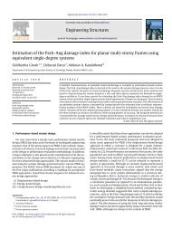
ductility-based seismic design of steel plate shear walls: practical ...
ductility-based seismic design of steel plate shear walls: practical ...
ductility-based seismic design of steel plate shear walls: practical ...

You also want an ePaper? Increase the reach of your titles
YUMPU automatically turns print PDFs into web optimized ePapers that Google loves.
International Journal <strong>of</strong> Advanced Structural Engineering, Vol. 1, No. 2, Pages 93-110, December 2009<br />
© Islamic Azad University, South Tehran Branch<br />
Published online December 2009 at (http://journals.azad.ac.ir/IJASE)<br />
DUCTILITY-BASED SEISMIC DESIGN OF STEEL PLATE SHEAR<br />
WALLS: PRACTICAL APPLICATION USING STANDARD SECTIONS<br />
Mayank K. Gupta 1 , Swapnil B. Kharmale 2 and Siddhartha Ghosh 3<br />
Department <strong>of</strong> Civil Engineering, Indian Institute <strong>of</strong> Technology Bombay, Mumbai, India<br />
Received 21 November 2009<br />
Revised 4 December 2009<br />
Accepted 7 December 2009<br />
Over the past decade <strong>of</strong> extensive research works, the thin un-stiffened <strong>steel</strong> <strong>plate</strong> <strong>shear</strong> wall<br />
(SPSW) has now emerged as a promising lateral load resisting system. Considering the<br />
demand <strong>of</strong> performance-<strong>based</strong> <strong>seismic</strong> <strong>design</strong> (PBSD) philosophy in current and future<br />
<strong>seismic</strong> <strong>design</strong> codes, a <strong>ductility</strong>-<strong>based</strong> <strong>design</strong> was recently proposed for SPSW systems with<br />
pin-connected boundary beams. However, the effectiveness <strong>of</strong> that method was not tested<br />
using standard <strong>steel</strong> sections. The focus <strong>of</strong> this paper is to check the applicability <strong>of</strong> that<br />
PBSD procedure for <strong>practical</strong> <strong>design</strong>s <strong>of</strong> SPSW systems in the US and Indian context, using<br />
standard rolled <strong>steel</strong> sections available commercially in these countries. Based on sample<br />
<strong>design</strong> case studies on 4-story test buildings, the method is found to be a practicable solution<br />
for PBSD <strong>of</strong> SPSW systems. In addition, the distribution <strong>of</strong> inter-story drift over the height <strong>of</strong><br />
the structure is also found to be suitable for adopting in <strong>design</strong> guidelines. The need for<br />
widening the range <strong>of</strong> available Indian Standard sections for realistic PBSD applications is<br />
recommended <strong>based</strong> on this study.<br />
Keywords: <strong>steel</strong> <strong>plate</strong> <strong>shear</strong> <strong>walls</strong>, performance-<strong>based</strong> <strong>seismic</strong> <strong>design</strong>, <strong>ductility</strong>-<strong>based</strong> <strong>design</strong>,<br />
AISC <strong>steel</strong> sections, Indian Standard sections<br />
1. Introduction<br />
The thin unstiffened <strong>steel</strong> <strong>plate</strong> <strong>shear</strong> wall (SPSW) is now accepted as an efficient lateral load<br />
resisting system in building structures. Standard <strong>design</strong> guidelines or code specifications for<br />
1 Former Graduate Student<br />
2 Ph.D. Candidate<br />
3 Assistant Pr<strong>of</strong>essor<br />
Correspondence to: Dr. Siddhartha Ghosh, Dept. <strong>of</strong> Civil Engineering, Indian Institute <strong>of</strong> Technology Bombay,<br />
Powai, Mumbai 400076, India, E-mail: sghosh @ civil.iitb.ac.in<br />
93
M. K. Gupta et al.<br />
SPSW are available in many countries, including Canada (CSA 2001) and USA (AISC 2005a,<br />
Sabelli and Bruneau 2007). SPSWs are sometimes preferred over other lateral load resisting<br />
systems because <strong>of</strong> the various advantages they provide (Astaneh-Asl 2001); primarily,<br />
substantial <strong>ductility</strong>, high initial stiffness, fast pace <strong>of</strong> construction, and the reduction in <strong>seismic</strong><br />
mass. However, it should be noted that SPSWs are yet to gain wide acceptance in structural<br />
engineering practice similar to what <strong>steel</strong> moment frames or reinforced concrete <strong>shear</strong> <strong>walls</strong> have<br />
gained. The <strong>design</strong> <strong>of</strong> SPSW was implemented as early as 1970 as a primary (lateral) load<br />
resisting system. Initially, only heavily stiffened SPSWs, with closely spaced horizontal and<br />
vertical stiffeners, were used in order to resist the <strong>shear</strong> forces within their elastic buckling limits.<br />
Examples <strong>of</strong> such constructions are the Sylmar Hospital in Los Angeles and the Nippon Steel<br />
Building in Tokyo. These systems were not suitable for implementing in earthquake resistant<br />
<strong>design</strong> <strong>of</strong> structures effectively. Analytical and experimental research works on the response <strong>of</strong><br />
SPSW against lateral loads carried out primarily in Canadian, US and UK universities, showed<br />
that the post-buckling ductile behaviour <strong>of</strong> the thin unstiffened SPSW is much more effective<br />
against <strong>seismic</strong> shaking than the elastic behaviour <strong>of</strong> the heavily stiffened SPSW. A list <strong>of</strong><br />
important works is available in (Berman et al. 2005). The unstiffened <strong>plate</strong>s, under cyclic load<br />
reversals, exhibit very stable hysteretic energy dissipation behaviour along with significant<br />
<strong>ductility</strong>, which make them very good lateral load resisting systems. However, the <strong>design</strong> codes<br />
that incorporate <strong>seismic</strong> <strong>design</strong> using SPSW, such as the CAN/CSA-16 (CSA 2001), the AISC<br />
Seismic Provisions (AISC 2005a) or the AISC <strong>design</strong> guide for <strong>steel</strong> <strong>plate</strong> <strong>shear</strong> <strong>walls</strong> (Sabelli<br />
and Bruneau 2007), so far, have not been able to fully exploit the <strong>ductility</strong> capacity since they<br />
incorporate this capacity implicitly (only through a force reduction factor, R).<br />
Considering the general gradual shift <strong>of</strong> earthquake resistant <strong>design</strong> <strong>of</strong> structural systems from<br />
simplified force-<strong>based</strong> deterministic <strong>design</strong> methods towards performance-<strong>based</strong> <strong>seismic</strong> <strong>design</strong><br />
(PBSD) techniques, Ghosh et al. (2009) recently proposed a displacement/<strong>ductility</strong>-<strong>based</strong> <strong>design</strong><br />
methodology <strong>of</strong> <strong>steel</strong> <strong>plate</strong> <strong>shear</strong> wall systems with pin-connected boundary beams. The<br />
philosophy <strong>of</strong> PBSD emphasizes on better characterization <strong>of</strong> structural damage and on proper<br />
accounting for uncertainties involved in the <strong>design</strong> process. Considering this, the inelastic<br />
displacement- or <strong>ductility</strong>-<strong>based</strong> <strong>design</strong> approach was proposed as one <strong>of</strong> the prescriptive<br />
approaches <strong>of</strong> PBSD (SEAOC Vision 2000 Committee 1995). The method proposed by Ghosh et<br />
al. (2009) is a deterministic <strong>design</strong> technique which considers the target displacement <strong>ductility</strong><br />
ratio (μ t ) as the <strong>design</strong> criterion. Thus it can utilize the <strong>ductility</strong> capacity <strong>of</strong> SPSW systems<br />
efficiently. It should be noted that the existing <strong>design</strong> guidelines (CSA 2001, Sabelli and Bruneau<br />
2007) suggest the use <strong>of</strong> SPSW with rigid beam-to-column connections. A similar <strong>ductility</strong>-<strong>based</strong><br />
<strong>design</strong> method for such SPSW systems is currently being developed by the authors <strong>of</strong> this article.<br />
94<br />
/ IJASE: Vol. 1, No. 2, December 2009
Ductility-Based Seismic Design <strong>of</strong> Steel Plate Shear Walls<br />
The <strong>design</strong> methodology proposed by Ghosh et al. (2009) is <strong>based</strong> on the energy balance during<br />
inelastic deformation and an assumed yield mechanism. Their method aims at <strong>design</strong>ing a SPSW<br />
system to have a specific inelastic drift/displacement <strong>ductility</strong> under a given earthquake scenario.<br />
They applied this method for <strong>design</strong>ing a 4-story <strong>steel</strong> structure with pin-connected beams with<br />
one SPSW bay, subjected to various ground motion scenarios and for different target <strong>ductility</strong><br />
ratios. The method was found to be effective for those scenarios and for various <strong>steel</strong> <strong>plate</strong> panel<br />
aspect ratios. However, one major limitation <strong>of</strong> their work was that they considered hypothetical<br />
sections for <strong>design</strong>ing the column sections (that is, vertical boundary elements or VBEs). These<br />
hypothetical sections conformed to a P-M interaction similar to what AISC-LRFD recommends<br />
(AISC 2005b), but the cross-sectional dimensions did not specifically belong to any section<br />
available in the <strong>steel</strong> tables provided by AISC, or anywhere else. The required <strong>design</strong> values (for<br />
example, required plastic moment capacity, M u ) were considered to be the section properties<br />
provided, in their <strong>design</strong> examples. Although, these hypothetical sections were suitable for<br />
checking how good the proposed theoretical <strong>design</strong> framework is, the <strong>design</strong> case studies<br />
presented by Ghosh et al. (2009) were not useful from a <strong>practical</strong> <strong>design</strong> perspective. A structural<br />
<strong>design</strong>er would like to see if the <strong>design</strong> method proposed in their work is also useful while using<br />
standard sections available in the market. The present paper aims at addressing this issue by<br />
applying Ghosh et al.’s (2009) <strong>ductility</strong>-<strong>based</strong> <strong>design</strong> methodology to a similar 4-story SPSW<br />
system with pin-connected beams under various ground motion scenarios and for different target<br />
<strong>ductility</strong> ratios, but using standard sections for the VBEs. Standard sections available in the US as<br />
per AISC (2005b) are used for a large set <strong>of</strong> <strong>design</strong> cases presented in this article. In addition, a<br />
few <strong>design</strong> cases are presented using standard sections available in India, as per the<br />
corresponding Indian Standard (BIS 1964). The effectiveness <strong>of</strong> using these sections for the<br />
proposed <strong>design</strong> method is checked <strong>based</strong> on how closely the real <strong>design</strong>s get to the target<br />
<strong>ductility</strong> ratios. These results are also compared with the outcome <strong>of</strong> the same <strong>design</strong>s using<br />
hypothetical sections created by Ghosh et al. (2009). The present paper also addresses the issue <strong>of</strong><br />
using actual values <strong>of</strong> the angle <strong>of</strong> inclination <strong>of</strong> principal tensile stress (α t ) in individual <strong>steel</strong><br />
<strong>plate</strong>s in the multi-strip analysis (Thorburn et al. 1983) <strong>of</strong> SPSW systems. Ghosh et al. (2009)<br />
considered only an average value (over all 4 stories) <strong>of</strong> α t in their analyses instead <strong>of</strong> the actual α t<br />
for a particular story. Overall, the primary focus <strong>of</strong> the present article is to check the viability <strong>of</strong><br />
<strong>practical</strong> application <strong>of</strong> a proposed performance-<strong>based</strong> <strong>seismic</strong> <strong>design</strong> method for SPSW systems<br />
in the US and Indian context.<br />
The next section briefly reviews the <strong>design</strong> methodology proposed by Ghosh et al. (2009) and<br />
provides the step-wise <strong>design</strong> method. Case study 1, in Section 3, deals with the application <strong>of</strong><br />
this method using standard AISC sections. The use <strong>of</strong> standard Indian sections is discussed in<br />
Section 4 (Case study 2). Section 5 provides a summary and the significant conclusions <strong>based</strong> on<br />
the work presented in this article.<br />
IJASE: Vol. 1, No. 2, December 2009 / 95
M. K. Gupta et al.<br />
2. Design Method Proposed by Ghosh et al. (2009)<br />
The <strong>ductility</strong>-<strong>based</strong> <strong>design</strong> method used here is <strong>based</strong> on equating the inelastic energy demand on<br />
a structural system with the inelastic work done through the plastic deformations for a monotonic<br />
loading up to the target drift. This section presents a brief overview <strong>of</strong> the primary <strong>design</strong><br />
formulation presented in (Ghosh et al. 2009). A simple SPSW system is considered for this where<br />
the beams are pin-connected at their ends to the columns, while the columns are fixed at their<br />
bases and are continuous along the height <strong>of</strong> the system, as shown in Figure 1(a).<br />
(a)<br />
(b)<br />
Figure 1. a) Schematic <strong>of</strong> the SPSW system; b) Selected yield mechanism<br />
The total strain energy (elastic and plastic) which is imparted to an inelastic system, is estimated<br />
as:<br />
2<br />
⎛ 1 2 ⎞ 1 ⎛ T ⎞<br />
Ee<br />
+ E<br />
p<br />
= γ ⎜ MSv<br />
⎟ = γM<br />
⎜ Ce<br />
g ⎟<br />
(1)<br />
⎝ 2 ⎠ 2 ⎝ 2π<br />
⎠<br />
where, E e is elastic strain energy demand, E p is plastic strain energy demand, γ is energy<br />
modification factor, M is total mass <strong>of</strong> the structure, S v is pseudo velocity corresponding to T, T<br />
is fundamental period, C e is elastic force coefficient, and g is gravitational acceleration. The<br />
energy modification factor is calculated <strong>based</strong> on the target <strong>ductility</strong> ratio <strong>of</strong> the system (μ t) and<br />
<strong>ductility</strong> reduction factor (R), as:<br />
2 1<br />
= μ t<br />
−<br />
γ (2)<br />
2<br />
R<br />
96<br />
/ IJASE: Vol. 1, No. 2, December 2009
Ductility-Based Seismic Design <strong>of</strong> Steel Plate Shear Walls<br />
The elastic force coefficient (C e ) is defined in terms <strong>of</strong> the <strong>design</strong> pseudo acceleration (A) or the<br />
<strong>design</strong> (elastic) base <strong>shear</strong> (V e ):<br />
A Ve<br />
Ce = =<br />
(3)<br />
g W<br />
where, W is the <strong>seismic</strong> weight <strong>of</strong> the structure. The structure is idealized as an inelastic<br />
equivalent single degree system by selecting a typical yield mechanism for the peak monotonic<br />
demand, where the mechanism is composed <strong>of</strong> yielding <strong>of</strong> all the <strong>plate</strong>s and plastic hinge<br />
formation at the base <strong>of</strong> the boundary columns (Figure 1b). The elastic strain energy demand (E e )<br />
during this monotonic push is calculated <strong>based</strong> on the yield base <strong>shear</strong>, V y , and substituting this in<br />
Equation (1), we get the plastic energy demand (E p ) as:<br />
2<br />
2<br />
WT g ⎡<br />
⎤<br />
2 ⎛Vy<br />
⎞<br />
E = ⎢ −<br />
⎜<br />
⎟<br />
p<br />
γC<br />
⎥<br />
2 e<br />
(4)<br />
8π<br />
⎢<br />
⎣ ⎝ W ⎠ ⎥<br />
⎦<br />
This E p is equated with the inelastic work done (W p ) through all the plastic deformations in the<br />
SPSW system:<br />
W<br />
p<br />
=<br />
n<br />
∑<br />
i=<br />
1<br />
P h θ + 2M<br />
θ<br />
(5)<br />
i<br />
si<br />
where n is number <strong>of</strong> stories, P i is plastic <strong>shear</strong> capacity <strong>of</strong> the ith story <strong>steel</strong> <strong>plate</strong>, h si is ith interstory<br />
height, and M pc is plastic moment capacity at each column base, θ p is target plastic drift<br />
<strong>based</strong> on an assumed yield drift (θ y ) as shown in Figure 1(b) (an elastic-perfectly plastic<br />
behaviour is assumed here), and we get the required yield base <strong>shear</strong> (V y ) as:<br />
p<br />
pc<br />
p<br />
Vy<br />
W<br />
2 2<br />
C<br />
n<br />
2<br />
− α + α + 4γ<br />
e<br />
⎛ ⎞ 8θ<br />
pπ<br />
= , whereα<br />
= ⎜∑λihi<br />
⎟<br />
2<br />
2<br />
⎝ i=<br />
1 ⎠ T g<br />
(6)<br />
where, h i is ith floor height, θ p is target plastic drift <strong>based</strong> on an assumed yield drift (θ y ). The<br />
factor λ i (= F i /V y ) represents the <strong>shear</strong> force distribution in the SPSW system as discussed by<br />
Ghosh et al. (2009) Similar to their work, we adopt a distribution <strong>based</strong> on statistical studies on<br />
<strong>steel</strong> MRF systems (Lee and Goel 2001). However, as shown by Ghosh et al. (2009), other<br />
commonly used <strong>shear</strong> distributions, such as the one proposed for <strong>steel</strong> EBF systems (Chao and<br />
Goel 2005), or the one in IBC 2006 (ICC 2006), can also be adopted.<br />
The required <strong>plate</strong> thickness at each story is obtained using the following equation:<br />
2Pi<br />
2V<br />
i<br />
ti<br />
= =<br />
(7)<br />
0.95F<br />
L 0.95F<br />
L<br />
y<br />
where, V i is ith story <strong>shear</strong> demand, F y is material yield strength and L is bay width. The base<br />
column moment capacity (M pc ) is obtained as per recommendations by Roberts (1995).<br />
y<br />
IJASE: Vol. 1, No. 2, December 2009 / 97
M. K. Gupta et al.<br />
2<br />
t h 1 1<br />
M = F y<br />
pc<br />
16<br />
(8)<br />
The <strong>design</strong> axial force (P c ) on the columns is calculated <strong>based</strong> on the moment equilibrium about<br />
the base. The column section is selected from available <strong>steel</strong> tables as per AISC (2005b) or Indian<br />
Standard (BIS 1964) for these demands <strong>based</strong> on the code prescribed P-M interaction and the<br />
criterion for compact section. This <strong>design</strong> is further modified by tuning the pin-connected beam<br />
member so as to achieve actual <strong>ductility</strong> ratio closer to the target <strong>ductility</strong> ratio. A <strong>design</strong><br />
flowchart is provided in Figure 2 giving the individual <strong>design</strong> steps.<br />
Figure 2. Flowchart for the <strong>ductility</strong>-<strong>based</strong> <strong>design</strong> method (Ghosh et al. 2009)<br />
98<br />
/ IJASE: Vol. 1, No. 2, December 2009
Ductility-Based Seismic Design <strong>of</strong> Steel Plate Shear Walls<br />
3. Case Study 1: Application Using Standard AISC Sections<br />
A 4-story <strong>steel</strong> frame building with pinned beam to column connections (Figure 3) is <strong>design</strong>ed<br />
with one bay <strong>of</strong> <strong>steel</strong> <strong>plate</strong> <strong>shear</strong> <strong>walls</strong>. Initially we consider the SPSW bay to have a span equal<br />
to the story height. This span is later varied in order to consider <strong>design</strong> scenarios with various<br />
aspect ratios <strong>of</strong> the <strong>steel</strong> <strong>plate</strong> panel. The building is assumed to have <strong>seismic</strong> weights <strong>of</strong> 4693 kN<br />
per floor, except for the ro<strong>of</strong> where it is 5088 kN. The SPSW is <strong>design</strong>ed against specific<br />
earthquake records for selected target <strong>ductility</strong> ratio (μ t ) values. This <strong>ductility</strong> ratio is defined in<br />
terms <strong>of</strong> the ro<strong>of</strong> displacement. Three strong motion records from the 1994 Northridge, USA and<br />
1995 Kobe, Japan earthquakes (Table 1) are used for this case study. Each <strong>design</strong> is identified by<br />
a ground motion and a target <strong>ductility</strong> ratio. The same structure, <strong>design</strong> cases and ground motion<br />
records were in (Ghosh et al. 2009) for <strong>design</strong>ing with hypothetical column sections. Similar to<br />
the approach used by them for measuring the effectiveness <strong>of</strong> the <strong>design</strong>s, the new <strong>design</strong>s with<br />
standard sections available from AISC tables (AISC 2005b) are checked against the same records<br />
through nonlinear response-history analysis in order to obtain the achieved <strong>ductility</strong> ratio (μ a ).<br />
Details for all the <strong>design</strong>s and analyses presented here (including the results shown in the next<br />
section) are available in a detailed report (Gupta 2009).<br />
Figure 3. Configuration <strong>of</strong> the 4-story study frame with SPSW<br />
The assumption <strong>of</strong> a suitable yield drift (θ y ) is <strong>based</strong> on observed behaviour (under static<br />
incremental loads) <strong>of</strong> SPSW systems. Like most other <strong>design</strong> procedures, the proposed procedure<br />
also needs an initial assumption <strong>of</strong> the fundamental time period (T), which involves iteration. The<br />
number <strong>of</strong> iterations needed to reach convergence depends on the experience <strong>of</strong> a <strong>design</strong>er. The<br />
actual required thicknesses <strong>of</strong> the SPSW panels as per the <strong>design</strong> calculation are provided in each<br />
<strong>design</strong>, without any due consideration to the availability <strong>of</strong> such precise thicknesses for <strong>steel</strong><br />
sheets. However, the column sections provided (with moment capacity M u and axial force<br />
capacity P u ) are <strong>based</strong> on available sections in the market (or at least in the <strong>design</strong> codes) <strong>design</strong><br />
IJASE: Vol. 1, No. 2, December 2009 / 99
M. K. Gupta et al.<br />
requirements (M pc and P c ). This is the primary difference with the sample <strong>design</strong> cases studied by<br />
Ghosh et al. (2009).<br />
Table 1. Details <strong>of</strong> earthquake records used for <strong>design</strong><br />
Earthquake Date Station Component PGA Code used<br />
Northridge Jan 17, 1994 Sylmar Converter Horiz.-052 0.612g SYL<br />
Kobe Jan 16, 1995 KJMA Horiz.-000 0.812g KJM<br />
Kobe Jan 16, 1995 Takarazuka Horiz.-000 0.692g TAZ<br />
As mentioned earlier, the <strong>steel</strong> <strong>plate</strong> is modelled using the multi-strip modelling technique<br />
(Thorburn et al. 1983) for nonlinear static and response-history analyses, in which the diagonal<br />
strip/truss members are aligned along the principal tensile direction (α t ) <strong>of</strong> the <strong>plate</strong> (Timler and<br />
Kulak 1983):<br />
tL<br />
1+<br />
2Ac<br />
tan 4<br />
α<br />
t<br />
=<br />
(9)<br />
3<br />
⎛ h ⎞<br />
+ th ⎜<br />
1 s<br />
1<br />
⎟<br />
s<br />
+<br />
⎝ Ab<br />
360I<br />
c<br />
L ⎠<br />
where, A c = cross-sectional area <strong>of</strong> the bounding column, I c = moment <strong>of</strong> inertia <strong>of</strong> the bounding<br />
column, A b = cross-sectional area <strong>of</strong> the bounding beam, and t = <strong>plate</strong> thickness. 10 strips, the<br />
minimum number recommended in previous literatures, are used to model each <strong>plate</strong> panel. The<br />
actual α t for each story are used for all the analyses, whereas Ghosh et al. (2009) have used an<br />
average value for all 4 stories. The SPSW system is modelled and analyzed using the structural<br />
analysis program DRAIN-2DX (Prakash et al., 1993) using nonlinear truss and beam-column<br />
elements. For all the elements the material is assumed to be elastic-perfectly plastic <strong>steel</strong> with<br />
yield stress, F y = 344.74 MPa (= 50 ksi), and without any overstrength factor. The system is<br />
modelled using a lumped mass model with 5% Rayleigh damping (in the first two modes) for the<br />
response-history analysis. Geometric nonlinearity and the nominal lateral stiffness from the<br />
gravity frames are neglected in these analyses. The detail <strong>design</strong> calculations for a sample <strong>design</strong><br />
case (Design III) are provided in Appendix.<br />
Table 2 presents the results for <strong>design</strong>s corresponding to <strong>plate</strong> aspect ratio (h s :L) 1:1. Each <strong>design</strong><br />
is identified here with a specific record and the target <strong>ductility</strong> ratio it is <strong>design</strong>ed for. This table<br />
also provides a measure <strong>of</strong> the effectiveness <strong>of</strong> the proposed <strong>design</strong> procedure <strong>based</strong> on how<br />
close the achieved <strong>ductility</strong> is to the target. The absolute maximum difference measured as<br />
percentage <strong>of</strong> μ t is found to be 37.0%, whereas the mean difference is –16.1%. For comparison,<br />
results for these <strong>design</strong> cases using hypothetical column section, as per Ghosh et al. (2009), are<br />
also presented in the same table. The results show that there is no significant change in the results<br />
for replacing the hypothetical section with a standard AISC section. The <strong>design</strong> with an AISC<br />
100/ IJASE: Vol. 1, No. 2, December 2009
Ductility-Based Seismic Design <strong>of</strong> Steel Plate Shear Walls<br />
section remains as effective as the one with a hypothetical column section. Table 2 presents the<br />
results for <strong>design</strong> cases when the assumed beam (W14×145) section is not tuned. Table 3<br />
presents the results when 4 <strong>of</strong> the <strong>design</strong>s here presented in Table 2 are revised through beam<br />
tuning. The result improves for each <strong>of</strong> the revised cases and overall (for 4 <strong>design</strong>s) the mean<br />
difference changes from –16.1% to 0.15%. Similar improvements in results were also observed<br />
for the <strong>design</strong> cases with hypothetical column section that are presented alongside in Table 3.<br />
Table 2. Result summary for <strong>design</strong>s with AISC sections (<strong>steel</strong> panel aspect ratio 1:1)<br />
Design Record μ t<br />
AISC section Hypothetical<br />
μ a % difference μ a % difference<br />
I SYL 2 1.53 –23.5 1.83 –8.50<br />
II SYL 3 2.66 –11.3 2.87 –4.33<br />
III SYL 4 3.34 –16.5 3.20 –20.0<br />
IV KJM 2 2.02 1.20 2.04 2.00<br />
V KJM 3 2.81 –6.33 2.96 –1.33<br />
VI KJM 4 2.52 –37.0 2.45 –38.8<br />
VII TAZ 2 1.94 –3.00 2.03 1.50<br />
VIII TAZ 3 2.02 –32.7 1.82 –39.3<br />
Average –16.1 –13.6<br />
Abs. max. 37.0 39.3<br />
Table 3. Result summary for beam-tuned systems with AISC sections (<strong>steel</strong> panel aspect ratio 1:1)<br />
Design Record μ t<br />
AISC section Hypothetical<br />
μ a % difference μ a % difference<br />
I-R SYL 2 2.11 5.50 2.05 2.50<br />
II-R SYL 3 3.04 1.33 3.05 1.67<br />
III-R SYL 4 3.63 –9.25 3.55 –11.3<br />
V-R KJM 3 3.09 3.00 3.02 0.670<br />
Average 0.15 –1.60<br />
Abs. max. 9.25 11.3<br />
In addition to the <strong>ductility</strong> achieved in terms <strong>of</strong> the peak ro<strong>of</strong> displacement, the displacement<br />
pr<strong>of</strong>iles are also studied in order to check for any localized concentration <strong>of</strong> plasticity in any<br />
story. Figure 4 and Figure 5 present the displacement pr<strong>of</strong>iles at the instant <strong>of</strong> peak ro<strong>of</strong> drift for<br />
the three Northridge and two Kobe (Takarazuka) <strong>design</strong>s. These figures show that the <strong>design</strong><br />
procedure remains very effective, even while using standard column sections, in distributing drift<br />
almost uniformly over the height <strong>of</strong> the building for these five <strong>design</strong> cases.<br />
In terms <strong>of</strong> using the actual angle <strong>of</strong> inclination <strong>of</strong> the tension strips (α t ), the change in analysis<br />
results for these <strong>design</strong> cases is found to be almost negligible. For all the <strong>design</strong> cases, α t is<br />
maximum at the lowest story and it decreases as we go up. The difference between the maximum<br />
IJASE: Vol. 1, No. 2, December 2009 / 101
M. K. Gupta et al.<br />
and minimum α t values for any <strong>design</strong> is below 1.5° (Gupta 2009). Based on this set <strong>of</strong> 24<br />
sample <strong>design</strong> cases, it can be recommended that an average α t can be used for all stories for the<br />
analysis <strong>of</strong> a SPSW system. This will reduce much <strong>of</strong> the computation in creating an analytical<br />
model <strong>of</strong> the structure.<br />
Figure 4. Displacement pr<strong>of</strong>iles at peak ro<strong>of</strong> displacement for Designs I, II and III<br />
Figure 5. Displacement pr<strong>of</strong>iles at peak ro<strong>of</strong> displacement for Designs VII and VIII<br />
With regards to tuning <strong>of</strong> boundary beams, Ghosh et al. (2009) suggested that if the achieved<br />
<strong>ductility</strong> ratio is less than the target, a closer <strong>ductility</strong> ratio can be achieved by reducing the pinconnected<br />
beam section, and vice versa. A detailed and closer look at this issue reveals that this is<br />
102/ IJASE: Vol. 1, No. 2, December 2009
Ductility-Based Seismic Design <strong>of</strong> Steel Plate Shear Walls<br />
not always true, although this recommendation generally holds good. Figure 6 presents the beam<br />
tuning results summary for Design III, where the achieved <strong>ductility</strong> ratio values are written next<br />
to the corresponding beam section selected. For μ t = 4, the first trial with an assumed beam<br />
section <strong>of</strong> W14×145 gives μ a = 3.34. As we select a lighter section (W14×43) for the beam, the<br />
achieved <strong>ductility</strong> ratio goes up to 3.63. However, for the next three trials, with reducing beam<br />
sections, the increase in <strong>ductility</strong> ratio is negligible, and for the two lightest beam sections<br />
(W12×16 and W12×14) the achieved <strong>ductility</strong> ratio again starts reducing. It can be concluded<br />
from this study that the achieved <strong>ductility</strong> ratio is not a monotonic function <strong>of</strong> the capacity <strong>of</strong> the<br />
pin-connected beam.<br />
Figure 6. Change in the achieved <strong>ductility</strong> ratio due to beam tuning for Design III; (The number next to<br />
the beam section provides the corresponding μ a )<br />
3.1. Designs for Steel Panel Aspect Ratios <strong>of</strong> 1:1.5 and 1:2<br />
The same <strong>ductility</strong>-<strong>based</strong> <strong>design</strong> method is applied to the <strong>design</strong>s <strong>of</strong> SPSW configurations with<br />
panel aspect ratios (h s :L) other than 1:1. For this, we change the span <strong>of</strong> the SPSW bay <strong>of</strong> the<br />
original structure (Figure 1) to 1.5 times and 2 times <strong>of</strong> the original. The 4-story structure remains<br />
the same otherwise. A similar exercise was conducted for <strong>design</strong>s with hypothetical column<br />
sections as well. The new <strong>design</strong>s (8 <strong>design</strong>s for each aspect ratio) are carried out following the<br />
procedure illustrated in Figure 2, and the beam dimensions are also fine tuned in order to achieve<br />
<strong>ductility</strong> closer to the target. Tables 4 and 5 provide the details on these <strong>design</strong>s with aspect ratios<br />
(h s :L) 1:1.5 and 1:2. The differences between the target and the achieved <strong>ductility</strong> are also<br />
provided similar to Table 2. These results show that the proposed <strong>design</strong> procedure remains very<br />
IJASE: Vol. 1, No. 2, December 2009 / 103
M. K. Gupta et al.<br />
effective for aspect ratios other than 1:1 as well. For <strong>design</strong>s with aspect ratio 1:1.5 (Table 4), the<br />
absolute maximum difference between the achieved and target <strong>ductility</strong> ratio, measured as<br />
percentage <strong>of</strong> μ t , is found to be 11.3%, whereas the mean difference is –3.79%. The<br />
corresponding values for <strong>design</strong>s with hypothetical sections as presented in the same table were<br />
20.3% and –4.45%, respectively. These data show that the <strong>design</strong>s are almost same – if not<br />
slightly better, overall – in terms <strong>of</strong> achieving the target <strong>ductility</strong> while using the standard AISC<br />
sections. For <strong>design</strong>s with aspect ratio 1:2, the <strong>design</strong>s using standard AISC sections remain<br />
similarly effective in achieving the target <strong>ductility</strong> (Table 5). The absolute maximum and the<br />
mean difference values for the <strong>design</strong>s with aspect ratio 1:2 are 13.3% and –1.17%, respectively.<br />
For <strong>design</strong>s with hypothetical column sections the absolute maximum and the mean differences<br />
between μ t and μ a were17.5% and –4.52%, respectively.<br />
These results altogether illustrate very clearly that we can achieve <strong>design</strong>s sufficiently close to<br />
the target for the range <strong>of</strong> aspect ratios from 1:1 to 1:2, while using standard AISC sections for<br />
the <strong>ductility</strong>-<strong>based</strong> <strong>design</strong> <strong>of</strong> SPSW systems, and the effectiveness <strong>of</strong> these <strong>design</strong>s is very similar<br />
to the <strong>design</strong>s presented by earlier researchers using hypothetical (“capacity = demand”) column<br />
sections. The primary reason for this success with the AISC sections is that the selected column<br />
sections for any <strong>design</strong> provides bending moment and axial force capacities very close to the<br />
demands for that <strong>design</strong>.<br />
Table 4. Result summary for <strong>design</strong>s with AISC sections (<strong>steel</strong> panel aspect ratio 1:1.5)<br />
Design Record μ t<br />
AISC section Hypothetical<br />
μ a % difference μ a % difference<br />
IX SYL 2 1.90 –5.00 2.01 0.500<br />
X SYL 3 3.23 7.67 2.99 –0.333<br />
XI SYL 4 3.80 –5.00 3.75 –6.25<br />
XII KJM 2 1.96 –2.00 1.98 –1.00<br />
XIII KJM 3 2.68 –10.7 2.77 –7.67<br />
XIV TAZ 2 2.01 0.50 2.07 3.50<br />
XV TAZ 3 2.66 –11.3 2.39 –20.3<br />
XVI TAZ 4 3.82 –4.50 3.84 –4.00<br />
Average –3.79 –4.45<br />
Abs. max. 11.3 20.3<br />
104/ IJASE: Vol. 1, No. 2, December 2009
Ductility-Based Seismic Design <strong>of</strong> Steel Plate Shear Walls<br />
Table 5. Result summary for <strong>design</strong>s with AISC sections (<strong>steel</strong> panel aspect ratio 1:2)<br />
Design Record μ t<br />
AISC section Hypothetical<br />
μ a % difference μ a % difference<br />
XVII SYL 2 1.92 –4.00 1.91 –4.50<br />
XVIII SYL 3 3.11 3.67 3.02 0.670<br />
XIX SYL 4 3.75 –6.25 3.76 –6.00<br />
XX KJM 2 2.17 8.50 1.97 –1.50<br />
XXI KJM 3 3.15 5.00 3.13 4.33<br />
XXII KJM 4 3.60 –10.0 3.30 –17.5<br />
XXIII TAZ 2 2.14 7.00 2.08 4.00<br />
XXIV TAZ 3 2.60 –13.3 2.53 –15.7<br />
Average –1.17 –4.52<br />
Abs. max. 13.3 17.5<br />
4. Case Study 2: Applications Using Indian Standard Sections<br />
The same <strong>ductility</strong>-<strong>based</strong> <strong>design</strong> method is also applied for the <strong>design</strong> <strong>of</strong> the 4-story SPSW<br />
structure, mentioned in the previous section, using Indian Standard sections. The primary reason<br />
for checking the same <strong>design</strong> method with another set <strong>of</strong> standard sections is that the <strong>steel</strong> tables<br />
as per the Indian Standard (BIS 1964) do not cover a similar wide range (as AISC) in terms <strong>of</strong><br />
ultimate moment and axial force capacities <strong>of</strong> the rolled sections. Besides, the number <strong>of</strong> sections<br />
available in that range is also less compared to the AISC tables (AISC 2005b). These limitations<br />
may result in: a) standard rolled sections not being available for <strong>design</strong>s subjected to strong<br />
earthquakes and low target <strong>ductility</strong> ratios, and b) capacities <strong>of</strong> the actual section provided being<br />
very different from the <strong>design</strong> requirements or demands. In addition, this may also reduce the<br />
effectiveness <strong>of</strong> tuning the pin-connected beams to achieve <strong>ductility</strong> ratios closer to the target.<br />
It is observed that standard rolled sections are not available in SP: 6(1) (BIS 1964) or the current<br />
IS: 800 tables (BIS 2007) to meet the demands for <strong>design</strong>s subjected to the records in Table 1,<br />
even for μ t up to 4. Therefore, for these <strong>design</strong> cases we scale down the selected records. The<br />
<strong>design</strong> scenarios for a few sample <strong>design</strong>s with Indian Standard sections with the scaled records<br />
and the selected target <strong>ductility</strong> ratios are provided in Table 6. The <strong>design</strong> procedure remains the<br />
same as in the previous section. Yield stress for these sections are considered to be F y = 250<br />
MPa. The results <strong>of</strong> these three sample <strong>design</strong>s (including tuning <strong>of</strong> beams), along with their<br />
counterparts considering hypothetical column sections, are also provided in Table 6. These<br />
results show that the <strong>design</strong>s with Indian Standard sections are as effective in achieving the target<br />
<strong>ductility</strong> ratios as the <strong>design</strong>s with their hypothetical counterparts. The absolute maximum<br />
difference between the target and the achieved <strong>ductility</strong> ratio using Indian Standard sections is<br />
19.0% and the mean is –11.4%. The column sections used in these three <strong>design</strong>s are ISWB 550<br />
for Design XXV and ISWB 600 for Designs XXVI and XXVII. ISWB 600 is the heaviest section<br />
IJASE: Vol. 1, No. 2, December 2009 / 105
M. K. Gupta et al.<br />
as per SP: 6(1) (BIS 1964). The ground motion scale factors are so selected that the column<br />
bending moment and axial force demands are within the capacities this section. Although column<br />
sections were available to closely meet the <strong>design</strong> demands for these three cases, this may not be<br />
the case for all <strong>design</strong>s using Indian Standard sections because <strong>of</strong> the wide gaps (in terms <strong>of</strong><br />
capacity) that exist between two successive sections available in SP: 6(1). The difficulty <strong>of</strong> beam<br />
tuning using Indian rolled sections, resulting from the same lack <strong>of</strong> closely-spaced sections,<br />
cannot be judged from a comparison with the <strong>design</strong>s using hypothetical column sections,<br />
because those <strong>design</strong>s also use the Indian Standard sections for beams. In addition, for these<br />
<strong>design</strong> cases subjected to weak ground motion records and large μ t , the required thickness <strong>of</strong> the<br />
<strong>steel</strong> <strong>plate</strong> panel becomes very low. The commercial availability <strong>of</strong> such <strong>plate</strong>s may be a problem<br />
for <strong>practical</strong> <strong>design</strong> applications.<br />
Table 6. Result summary for <strong>design</strong>s with Indian Standard sections (<strong>steel</strong> panel aspect ratio 1:1)<br />
Design Record Scale factor μ t<br />
IS section<br />
Hypothetical<br />
μ a % difference μ a % difference<br />
XXV SYL 0.35 4 4.00 0 3.52 –12.0<br />
XXVI KJM 0.90 4 3.39 –15.3 3.34 –16.5<br />
XXVII TAZ 0.78 4 3.24 –19.0 3.28 –18.0<br />
Average –11.4 –15.5<br />
Abs. max. 19.0 18.0<br />
It should be stated, however, that the limitation in section capacities as per SP: 6(1) does not<br />
make the application <strong>of</strong> <strong>ductility</strong>-<strong>based</strong> <strong>design</strong> <strong>of</strong> SPSW for earthquake resistant <strong>design</strong> <strong>of</strong><br />
buildings in the Indian scenario somewhat im<strong>practical</strong>. The present study does not consider the<br />
use <strong>of</strong> built-up sections for boundary columns, which is expected to broaden the range <strong>of</strong><br />
application to a great degree, specifically for strong earthquake-low target <strong>ductility</strong> <strong>design</strong> cases.<br />
These sections will also let us achieve more effective <strong>design</strong>s as the capacities <strong>of</strong> the column can<br />
be easily tuned to the <strong>design</strong> requirements. The use <strong>of</strong> built-up sections need a detailed<br />
investigation both in terms <strong>of</strong> <strong>design</strong> advantage and economic viability, and this is beyond the<br />
scope <strong>of</strong> present article.<br />
5. Summary and Conclusions<br />
The focus <strong>of</strong> this paper is in the <strong>practical</strong> application <strong>of</strong> an inelastic displacement-<strong>based</strong> <strong>design</strong><br />
method, developed earlier, for <strong>steel</strong> <strong>plate</strong> <strong>shear</strong> wall systems. This method is applied to the <strong>design</strong><br />
<strong>of</strong> 4-story <strong>steel</strong> frame structures, with different <strong>steel</strong> panel aspect ratios, using standard AISC and<br />
Indian rolled sections. The following significant conclusions can be drawn from the work<br />
presented here:<br />
1. The applications using standard AISC sections are very satisfactory and as effective in<br />
106/ IJASE: Vol. 1, No. 2, December 2009
Ductility-Based Seismic Design <strong>of</strong> Steel Plate Shear Walls<br />
achieving the target <strong>ductility</strong> ratio as the hypothetical <strong>design</strong>s presented by Ghosh et al.<br />
(2009).<br />
2. Thus, the method discussed in Section 2 becomes a <strong>practical</strong> performance-<strong>based</strong> <strong>design</strong><br />
solution for earthquake resistant <strong>design</strong> problems. This method, as provided in the <strong>design</strong><br />
flowchart (Figure 2), is simple but efficient enough for adopting in standard <strong>design</strong><br />
guidelines.<br />
3. The use <strong>of</strong> the actual value <strong>of</strong> α t (inclination angle <strong>of</strong> the tension field) does not alter the<br />
results significantly. Therefore, the use <strong>of</strong> an average α t is recommended for <strong>practical</strong><br />
purpose. The ability to use average α t for analysis/<strong>design</strong> checking makes it more appealing<br />
to a practicing engineer.<br />
4. The use <strong>of</strong> Indian Standard sections following the same <strong>design</strong> method is also found to be<br />
satisfactory.<br />
5. However, due to the lack <strong>of</strong> available standard rolled Indian sections with large capacities, the<br />
application gets limited to weak earthquake-large <strong>ductility</strong> <strong>design</strong>s. In order to be able to<br />
utilize this or similar advanced earthquake <strong>design</strong> methods, the range <strong>of</strong> available sections in<br />
India needs to be enhanced.<br />
6. Also, more closely-spaced sections (in terms <strong>of</strong> section dimensions/capacities) need to be<br />
available to apply this method effectively in the Indian scenario. Built-up sections need to be<br />
explored in detail for application <strong>of</strong> the <strong>ductility</strong>-<strong>based</strong> SPSW <strong>design</strong> method in the Indian<br />
context.<br />
Appendix: Design Example <strong>of</strong> Case Study 1<br />
The detail <strong>design</strong> calculations for a sample <strong>design</strong> case (Design III) are provided here for<br />
example:<br />
• Selected record: SYL<br />
• Target <strong>ductility</strong> ratio selected for this <strong>design</strong>, μ t = 4<br />
• Yield drift (<strong>based</strong> on ro<strong>of</strong> displacement) assumed for <strong>design</strong>, θ y = 0.01<br />
• Plastic drift for the selected μ t and θ y , θ p = 0.03<br />
• Fundamental period <strong>of</strong> the structure, T = 0.90 sec<br />
• Pseudo velocity for T from the 5% SYL spectrum, S v = 2.26 m/sec<br />
• From Equation (2), γ = 0.44<br />
• Seismic weight <strong>of</strong> the system, W = 19.17×10 3 kN<br />
IJASE: Vol. 1, No. 2, December 2009 / 107
M. K. Gupta et al.<br />
• From Equation (3), C e = 1.606<br />
• From Equation (6), α = 4.09, and V y = 4.968×10 3 kN<br />
• Based on the assumed <strong>shear</strong> distribution, the <strong>design</strong> equivalent lateral forces, from top to<br />
bottom: F 4 = 3188 kN, F 3 = 981.7 kN, F 2 = 546.2 kN, and F 1 = 251.5 kN<br />
• Story <strong>shear</strong>s from top to bottom: V 4 = 3188 kN, V 3 = 4169 kN, V 2 = 4716 kN, and V 1 = 4968<br />
kN.<br />
• Plate thicknesses provided <strong>based</strong> on Equation (7), from top to bottom: t 4 = 4.51 mm, t 3 = 5.90<br />
mm, t 2 = 6.68 mm, and t 1 = 7.03 mm<br />
• Based on Equation (8), M pc = 2.483×10 3 kNm, and P c = 15.80×10 3 kN<br />
• Using P-M interaction, the demands on the boundary columns are calculated as: M u =<br />
7.852×10 3 kNm, and P u = 21.60×10 3 kN<br />
• Standard AISC column section selected for these demands: W36×330<br />
• Capacities <strong>of</strong> the selected column section: M u = 7.965×10 3 kNm, and P u = 21.73×10 3 kN<br />
The nonlinear pushover analysis gives a yield displacement <strong>of</strong> 0.103 m. The nonlinear responsehistory<br />
analysis subjected to the SYL record gives a peak ro<strong>of</strong> displacement <strong>of</strong> 0.344 m. The<br />
achieved <strong>ductility</strong> ratio (μ a ) is calculated as the ratio <strong>of</strong> peak ro<strong>of</strong> displacement to the ro<strong>of</strong><br />
displacement at yield, and comes to be 3.34 for this <strong>design</strong> case.<br />
Acknowledgements<br />
Support for this research on developing a displacement-<strong>based</strong> <strong>design</strong> method for <strong>steel</strong> <strong>plate</strong> <strong>shear</strong><br />
wall structures is provided by the Department <strong>of</strong> Science and Technology (DST), India. The<br />
findings and the opinions expressed herein are those <strong>of</strong> the authors and do not necessarily<br />
represent the views <strong>of</strong> DST.<br />
References<br />
AISC (2005a), “Seismic Provisions for Structural Steel Buildings”, American Institute <strong>of</strong> Steel<br />
Construction, Chicago, IL., USA.<br />
AISC (2005b), “Specifications for Structural Steel Buildings”, American Institute <strong>of</strong> Steel<br />
Construction, Chicago, IL., USA.<br />
Astaneh-Asl, A. (2001), “Steel tips: Seismic behavior and <strong>design</strong> <strong>of</strong> <strong>steel</strong> <strong>shear</strong> <strong>walls</strong>”, Technical<br />
Report, Structural Steel Education Council, Moraga, CA., USA.<br />
108/ IJASE: Vol. 1, No. 2, December 2009
Ductility-Based Seismic Design <strong>of</strong> Steel Plate Shear Walls<br />
Berman, J.W., Vian, D. and Bruneau, M. (2005), “Steel <strong>plate</strong> <strong>shear</strong> <strong>walls</strong>: From research to<br />
codification”, ASCE 2005 Structures Congress, New York, NY., USA., Pages 20-24.<br />
Bureau <strong>of</strong> Indian Standards (2007), “IS: 800-2007: Indian Standard Code <strong>of</strong> Practice for General<br />
Construction in Steel”, Bureau <strong>of</strong> Indian Standards, New Delhi, India.<br />
Bureau <strong>of</strong> Indian Standards (1964), “SP: 6(1)-1964: Handbook for Structural Engineers, No. 1,<br />
Structural Steel Sections”, Bureau <strong>of</strong> Indian Standards, New Delhi, India.<br />
CAN/CSA S16-2001 (2001), “Limit State Design <strong>of</strong> Steel Structures”, Canadian Standards<br />
Association, Willowdale, ON., Canada.<br />
Chao, S.H. and Goel, S.C. (2005), “Performance-<strong>based</strong> <strong>seismic</strong> <strong>design</strong> <strong>of</strong> EBF using target drift<br />
and yield mechanism as performance criteria”, Research Report UMCEE 05-05, Department <strong>of</strong><br />
Civil and Environmental Engineering, University <strong>of</strong> Michigan, Ann Arbor, MI., USA.<br />
Ghosh, S., Das, A. and Adam, F. (2009), “Design <strong>of</strong> <strong>steel</strong> <strong>plate</strong> <strong>shear</strong> <strong>walls</strong> considering inelastic<br />
drift demand”, Journal <strong>of</strong> Constructional Steel Research, Vol. 65, No. 7, Pages 1431-1437.<br />
Gupta, M.K. (2009), “Ductility-<strong>based</strong> <strong>design</strong> <strong>of</strong> <strong>steel</strong> <strong>plate</strong> <strong>shear</strong> <strong>walls</strong>: Practical application<br />
aspects”, M. Tech. Thesis, Department <strong>of</strong> Civil Engineering, Indian Institute <strong>of</strong> Technology<br />
Bombay, Mumbai, India.<br />
ICC (2006), “International Building Code 2006”, International Code Council, Whittier, CA.,<br />
USA.<br />
Lee, S.S. and Goel, S.C. (2001), “Performance <strong>based</strong> <strong>design</strong> <strong>of</strong> <strong>steel</strong> moment frames using target<br />
drift and yield mechanism”, Research Report UMCEE 01-17, Department <strong>of</strong> Civil and<br />
Environmental Engineering, University <strong>of</strong> Michigan, Ann Arbor, MI., USA.<br />
Newmark, N.M. and Hall, W.J. (1973), “Procedures and criteria for earthquake resistant <strong>design</strong>:<br />
Building practices for disaster mitigation”, Building Science Series, Vol. 46, National Bureau <strong>of</strong><br />
Standards, Washington, DC., USA., Pages 209-236.<br />
Prakash, V., Powell, G.H. and Campbell, S. (1993), “DRAIN-2DX: Base program description<br />
user guide - Version 1.10”, Report No. UCB/SEMM-93/17, University <strong>of</strong> California, Berkeley,<br />
CA., USA.<br />
Roberts, T.M. (1995), “Seismic resistance <strong>of</strong> <strong>steel</strong> <strong>plate</strong> <strong>shear</strong> <strong>walls</strong>”, Engineering Structures,<br />
Vol. 17, No. 5, Pages 344-351.<br />
Sabelli, R. and Bruneau, M. (2007), “Design Guide 20: Steel Plate Shear Walls”, American<br />
Institute <strong>of</strong> Steel Construction, Chicago, IL, USA.<br />
IJASE: Vol. 1, No. 2, December 2009 / 109
M. K. Gupta et al.<br />
SEAOC Vision 2000 Committee (1995), “Performance-Based Seismic Engineering <strong>of</strong><br />
Buildings”, Structural Engineers Association <strong>of</strong> California, Sacramento, CA., USA.<br />
Thorburn, L.J., Kulak, G.L. and Montgomery, C.J. (1983), “Analysis <strong>of</strong> <strong>steel</strong> <strong>plate</strong> <strong>shear</strong> <strong>walls</strong>”,<br />
Structural Engineering Report No. 107, Department <strong>of</strong> Civil Engineering, University <strong>of</strong> Alberta,<br />
Edmonton, AB., Canada.<br />
Timler, P.A. and Kulak, G.L. (1983), “Experimental study <strong>of</strong> <strong>steel</strong> <strong>plate</strong> <strong>shear</strong> <strong>walls</strong>”, Structural<br />
Engineering Report No. 114, Department <strong>of</strong> Civil Engineering, University <strong>of</strong> Alberta, Edmonton,<br />
AB., Canada.<br />
110/ IJASE: Vol. 1, No. 2, December 2009