to download this brochure - McGuire Air Compressors, Inc
to download this brochure - McGuire Air Compressors, Inc
to download this brochure - McGuire Air Compressors, Inc

You also want an ePaper? Increase the reach of your titles
YUMPU automatically turns print PDFs into web optimized ePapers that Google loves.
MCGUIRE AIR COMPRESSORS 1-888-229-9999<br />
MCGUIRE AIR COMPRESSORS 1-888-229-9999<br />
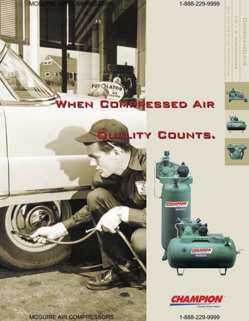
One and Two Stage Reciprocating<br />
1/2 – 5 Horsepower<br />
Commandair<br />
When Compressed <strong>Air</strong><br />
Quality Counts.
MCGUIRE AIR COMPRESSORS 1-888-229-9999<br />
COMMANDAIR<br />
PROVEN DESIGN…<br />
Now there is a high quality compressor<br />
for when you need dependable air power<br />
that’s a real value, <strong>to</strong>o. Champion’s<br />
full line of compact Commandair<br />
reciprocating air compressors are built<br />
<strong>to</strong> the same exact quality standards as<br />
our larger models, but sized for smaller<br />
air requirements, such as small industrial<br />
plants, schools, small au<strong>to</strong>motive centers<br />
and do-it-yourselfers.<br />
SINGLE-STAGE<br />
ELECTRIC DRIVEN<br />
The single-stage series of Commandair<br />
air compressor units are available from<br />
1/2 through 3 HP, with the option of<br />
horizontal, vertical style receivers, and<br />
base mounted units. <strong>Air</strong> pressure ratings<br />
are available up <strong>to</strong> 125 PSIG. Thermal<br />
overload protected mo<strong>to</strong>rs are standard<br />
on 1/2 through 1 HP, single phase, 115<br />
Volt units.<br />
TWO-STAGE<br />
ELECTRIC DRIVEN<br />
Available in sizes from 3/4 through<br />
2 HP with pressures ratings up <strong>to</strong><br />
175 PSIG. Two-stage Commandair air<br />
compressormodels are available mounted<br />
on horizontal, or a space-saving vertical<br />
receiver, or as a base mounted package.<br />
Thermal overload protected mo<strong>to</strong>r is<br />
standard on 3/4 HP, single phase, 115<br />
Volt units. 1750 RPM mo<strong>to</strong>rs are standard<br />
equipment on all packages.<br />
• Unamated aluminum cylinders with cast-iron<br />
liners combine maximum wear of iron with cooling<br />
efficiency of an aluminum casting. Multi-finned for<br />
superior heat dissipation and longer life.<br />
• Lightweight aluminum alloy pis<strong>to</strong>ns ensure proper<br />
reciprocating balance. Two compression rings and<br />
one oil-control ring are used for better oil control,<br />
less air blow-by and higher efficiency.<br />
• High density, high silicon die-cast aluminum alloy<br />
connecting rods minimize reciprocating weight<br />
and offer exceptional bearing life. All single-stage<br />
models have integral, precision bored crank pin<br />
and pis<strong>to</strong>n pin bearing <strong>to</strong> properly distribute<br />
bearing loads. (Also applies <strong>to</strong> first stage of two<br />
stage models; second stage has bronze bushing on<br />
pis<strong>to</strong>n pin end.)<br />
• High-quality Swedish Steel reed-type valves provide<br />
long life. Also, second stage of two-stage models<br />
feature single unit (disc valve) design.<br />
• Tapered roller bearings on two and three-cylinder<br />
models provide longer life.<br />
• Precision balanced flywheel has fan blades for<br />
maximum compressor cooling resulting in extended<br />
compressor life.<br />
• Rugged ductile iron crankshaft has large<br />
diameter throws for minimum bearing loads, and<br />
counterweights <strong>to</strong> minimize vibration.<br />
• Rugged cast iron crankcase designed <strong>to</strong> rigidly<br />
support the crankshaft and bearings. Convenient<br />
oil level sight gauge on 2 and 3 cylinder models,<br />
and large oil drain.<br />
• Removable cartridge-type intake filter features a<br />
10-micron rated element.<br />
COMPRESSOR DIMENSIONS<br />
Model A1, B1, C1 AV1 BV1 CV1 CW1 CAV1 CAW1<br />
A Base width 6¼ 7¼ 7¼ 7¼ 8 7¼ 8<br />
AA Pipe size ½ ½ ½ ½ ½ ½ ½<br />
AB Overall width 10¼ 18¼ 18½ 18½ 24½ 15¾ 20½<br />
B Base depth 3 3½ 3½ 3½ 3¾ 3½ 3¾<br />
BA Flywheel <strong>to</strong> hole 2 2 1¼ 1¼ 2 1¾ 2<br />
C Overall depth 7¼ 8 8 8 8¾ 8¾ 8¾<br />
D Base <strong>to</strong> shaft 3¼ 3¼ 3¼ 3¼ 4 3¼ 4<br />
E Hole spacing 2¾ 3¼ 3¼ 3¼ 3½ 3¼ 3½<br />
F Hole spacing 2¼ 2¾ 2¾ 2¾ 2¾ 2¾ 2¾<br />
H Hole dia. 1¼ ½ ½ ½ ½ ½ ½<br />
N Flywheel width 1¾ 1¾ 2¾ 2¾ 2½ 2½ 2½<br />
O Pump height 14½ 11¾ 11¾ 11¾ 16¼ 12¼ 16¼<br />
P Flywheel dia. *10¼ 10¼ 10¼ 10¼ 12¾ 12¾ 12¾<br />
V No. & Sections 1A 1A 2A 2A 2A 2A 2A<br />
W Flywheel <strong>to</strong> base 1½ 1½ ¾ ¾ 1¼ 1½ 1¼<br />
*A1 Pump with pressed steel flywheel - 9” diameter<br />
MCGUIRE AIR COMPRESSORS 1-888-229-9999
MCGUIRE AIR COMPRESSORS 1-888-229-9999<br />
MCGUIRE AIR COMPRESSORS 1-888-229-9999<br />
SINGLE STAGE – HORIZONTAL UNITS (Electric) - Model Matrix CESCAA<br />
HP<br />
Tank<br />
Cap<br />
Unit<br />
Model<br />
compressor<br />
Pump<br />
Model<br />
RPM<br />
90 PSIG<br />
CFM<br />
Displ<br />
CFM*<br />
Del’y<br />
Bores Stroke<br />
in. dia. in.<br />
No.<br />
cyc.<br />
Overall Dims.<br />
L x W x H<br />
in.<br />
Bolt<br />
Down<br />
L x W<br />
in.<br />
Net<br />
Weight<br />
approx.<br />
lbs.<br />
½ 30 30A5H A1 1020 2.8 1.8 1¾ 2 1 42 x 19 x 35¾ 20 x 11 122<br />
¾ 30 30B7H B1 725 3.7 2.4 2½ 2 1 42 x 19 x 35¾ 20 x 11 137<br />
1 30 30C10H C1 800 5.0 3.1 2¾ 2 1 42 x 19 x 35¾ 20 x 11 166<br />
1 30 30AV10H AV1 935 5.1 2.9 1¾ 2 2 42 x 21 x 34¼ 20 x 11 172<br />
1½ 30 30BV15H BV1 780 8.0 5.3 2½ 2 2 42 x 21 x 34¼ 20 x 11 180<br />
2 30 30CV20H CV1 775 9.7 6.7 2¾ 2 2 42 x 21 x 34¼ 20 x 11 188<br />
2 30 30CW20H CW1 580 10.9 7.2 2¾ 2 3 42 x 21 x 37¾ 20 x 11 203<br />
2 60 60CW20H CW1 580 10.9 7.2 2¾ 2 3 51 x 22 x 42¾ 28 x 18 294<br />
3 30 30CV30HS CV1 940 11.8 7.6 2¾ 2 2 42 x 21 x 33¼ 20 x 11 240<br />
3 30 30CW30HS CW1 895 16.8 10.5 2¾ 2 3 42 x 21 x 37¾ 20 x 11 290<br />
SINGLE STAGE – VERTICAL UNITS (Electric) - Model Matrix CESCAA<br />
HP<br />
Tank<br />
Cap<br />
Unit<br />
Model<br />
compressor<br />
Pump<br />
Model<br />
RPM<br />
90 PSIG<br />
CFM<br />
Displ<br />
CFM*<br />
Del’y<br />
Bores Stroke<br />
in. dia. in.<br />
No.<br />
cyc.<br />
Overall Dims.<br />
L x W x H<br />
in.<br />
Bolt Down<br />
L x W<br />
in.<br />
Net<br />
Weight<br />
approx.<br />
lbs.<br />
½ 30 30A5V A1 1020 2.8 1.8 1¾ 2 1 24 x 22 x 582¾ 4 on 18” BC 136<br />
¾ 30 30B7V B1 725 3.7 2.4 2½ 2 1 24 x 22 x 582¾ 4 on 18” BC 148<br />
1 30 30C10V C1 800 5.0 3.1 2¾ 2 1 24 x 22 x 582¾ 4 on 18” BC 152<br />
1 30 30AV10V AV1 935 5.1 2.9 1¾ 2 2 30 x 22 x 57¼ 4 on 18” BC 158<br />
1½ 30 30BV15V BV1 780 8.0 5.3 2½ 2 2 30 x 22 x 57¼ 4 on 18” BC 182<br />
2 30 30CV20V CV1 775 9.7 6.7 2¾ 2 2 30 x 22 x 57¼ 4 on 18” BC 190<br />
3 30 30CV30VS CV1 940 11.8 7.6 2¾ 2 2 30 x 22 x 57¼ 4 on 18” BC 245<br />
3 30 30CW30VS CW1 895 16.8 10.5 2¾ 2 3 30 x 24 x 612¾ 4 on 18” BC 295<br />
SINGLE STAGE – BASE-MOUNTED UNITS (Electric) - Model Matrix CEBCAA<br />
HP<br />
Unit<br />
Model<br />
compressor<br />
Pump<br />
Model<br />
RPM<br />
90 PSIG<br />
CFM<br />
Displ<br />
CFM*<br />
Del’y<br />
Bores Stroke No.<br />
in. dia. in. cyc.<br />
Overall Dims.<br />
L x W x H<br />
in.<br />
Bolt Down<br />
L x W<br />
in.<br />
½ BMA5 A1 1020 2.8 1.8 1¾ 2 1 18½ x 10¼ x 18 17 x 7¼ 56<br />
¾ BMB7 B1 725 3.7 2.4 2½ 2 1 18½ x 10¼ x 18½ 17 x 7¼ 63<br />
1 BMC10 C1 800 5.0 3.1 2¾ 2 1 18½ x 10¼ x 18½ 17 x 7¼ 76<br />
1 BMAV10 AV1 935 5.1 2.9 1¾ 2 2 20½ x 10¼ x 16¾ 17 x 7¼ 79<br />
1½ BMBV15 BV1 780 8.0 5.3 2½ 2 2 20½ x 10¼ x 17 17 x 7¼ 82<br />
2 BMCV20 CV1 775 9.7 6.7 2¾ 2 2 20½ x 10¼ x 17 17 x 7¼ 86<br />
2 BMCW20 CW1 580 10.9 7.2 2¾ 2 3 21½ x 13 x 19½ 25½ x 10¼ 93<br />
TWO STAGE – HORIZONTAL UNITS (Electric) - Model Matrix CESCAA<br />
HP<br />
Tank<br />
Cap<br />
Unit<br />
Model<br />
compressor<br />
Pump<br />
Model<br />
RPM<br />
90 PSIG<br />
CFM<br />
Displ<br />
CFM*<br />
Del’y<br />
Bores<br />
in. dia.<br />
Stroke<br />
in.<br />
No.<br />
cyc.<br />
Overall Dims.<br />
L x W x H<br />
in.<br />
Bolt<br />
Down<br />
L x W<br />
in.<br />
Net<br />
Weight<br />
approx.<br />
lbs.<br />
Net<br />
Weight<br />
approx.<br />
lbs.<br />
¾ 30 30CAV7H CAV1 590 3.7 2.6 2¾ & 1¾ 2 2 42 x 22 x 33¾ 20 x 11 183<br />
1 30 30CAV10H CAV1 780 4.9 3.8 2¾ & 1¾ 2 2 42 x 22 x 33¾ 20 x 11 190<br />
1 60 60CAV10H CAV1 780 4.9 3.8 2¾ & 1¾ 2 2 52 x 22 x 38¾ 28 x 18 280<br />
1½ 30 30CAW15H CAW1 565 7.1 5.4 2¾ (2) & 1¾ 2 3 42 x 22 x 37¾ 20 x 11 194<br />
1½ 60 60CAW15H CAW1 565 7.1 5.4 2¾ (2) & 1¾ 2 3 52 x 22 x 42¾ 28 x 18 280<br />
2 30 30CAW20H CAW1 720 9.0 6.7 2¾ (2) & 1¾ 2 3 42 x 22 x 37¾ 20 x 11 196<br />
2 60 60CAW20H CAW1 720 9.0 6.7 2¾ (2) & 1¾ 2 3 52 x 22 x 42¾ 28 x 18 287
MCGUIRE AIR COMPRESSORS 1-888-229-9999<br />
COMMANDAIR<br />
TWO STAGE – VERTICAL UNITS (Electric) - Model Matrix CESCAA<br />
HP<br />
Tank<br />
Cap<br />
Unit<br />
Model<br />
compressor<br />
Pump<br />
Model<br />
RPM<br />
90 PSIG<br />
CFM<br />
Displ<br />
CFM*<br />
Del’y<br />
Bores<br />
in. dia.<br />
Stroke<br />
in.<br />
No.<br />
cyc.<br />
Overall Dims.<br />
L x W x H<br />
in.<br />
Bolt Down<br />
L x W<br />
in.<br />
Net<br />
Weight<br />
approx.<br />
lbs.<br />
¾ 30 30CAV7V CAV1 590 3.7 2.6 2¾ & 1¾ 2 2 30 x 22 x 56¾ 4 on 18” BC 178<br />
1 30 30CAV10V CAV1 780 4.9 3.8 2¾ & 1¾ 2 2 30 x 22 x 56¾ 4 on 18” BC 182<br />
1½ 60 30CAW15V CAW1 565 7.1 5.4 2¾ (2) & 1¾ 2 3 33 x 22 x 69¾ 4 on 23” BC 315<br />
2 60 30CAW20V CAW1 720 9.0 6.7 2¾ (2) & 1¾ 2 3 33 x 22 x 69¾ 4 on 23” BC 322<br />
TWO STAGE – BASE-MOUNTED UNITS (Electric) - Model Matrix CEBCAA<br />
HP<br />
Unit<br />
Model<br />
compressor<br />
Pump<br />
Model<br />
RPM<br />
90 PSIG<br />
CFM<br />
Displ<br />
CFM*<br />
Del’y<br />
Bores<br />
in. dia.<br />
Stroke<br />
in.<br />
No.<br />
cyc.<br />
Overall Dims.<br />
L x W x H<br />
in.<br />
Bolt Down<br />
L x W<br />
in.<br />
¾ BMCAV7 CAV1 590 3.7 2.6 2¾ & 1¾ 2 2 21¼ x 10½ x 16¼ 17 x 7¼ 84<br />
1 BMCAV10 CAV1 780 4.9 3.8 2¾ & 1¾ 2 2 21¼ x 10½ x 16¼ 17 x 7¼ 87<br />
1½ BMCAW15 CAW1 565 7.1 5.4 2¾ (2) & 1¾ 2 3 31¼ x 13 x 19½ 25½ x 10¼ 88<br />
2 BMCAW20 CAW1 720 9.0 6.7 2¾ (2) & 1¾ 2 3 31¼ x 13 x 19½ 25½ x 10¼ 90<br />
Net<br />
Weight<br />
approx.<br />
lbs.<br />
SPRINKLER SYSTEMS: 40 PSIG SYSTEM (30 minutes maximum pumping time)<br />
HP<br />
Max<br />
Volume<br />
Gallons<br />
Unit<br />
Model<br />
Comp’ r<br />
Pump<br />
Model<br />
RPM<br />
CFM<br />
Displ<br />
CFM/FA*<br />
Del’y<br />
Dimensions in <strong>Inc</strong>hes<br />
A B C D E F G H<br />
½ 265 BMB-5SS B1 845 4.3 3.2 18½ 8¾ 16¾ ½ 15 NA 2½ 12¼ ½<br />
¾ 350 BMC-7SS C1 845 5.3 4.2 18½ 8¾ 16¾ ½ 15 NA 2½ 12¼ ½<br />
1 600 BMBV-10SS BV1 965 9.9 7.3 27 13¾ 14½ ½ 19½ 10¼ 2½ 7¾ ½<br />
1½ 745 BMCV-15SS CV1 960 12.0 9.0 27 13¾ 14½ ½ 19½ 10¼ 2½ 7¾ ½<br />
2 1050 BMCW-20SS CW1 900 16.9 12.7 29½ 13¾ 18¾ ½ 19½ 10¼ 2½ 9½ ½<br />
3 1625 BS-3SS S-20 655 25.1 19.7 29¼ 16¼ 23 ½ 26 14¼ 4 6½ ¾<br />
5 2180 BS-5SS S-20 980 37.5 26.4 29¼ 16¼ 23 ½ 26 14¼ 4 6½ ¾<br />
*Units tested in accordance with CAGI/PNEUROP acceptance test code PN2CPTC2 or PN2CPTC3<br />
Champion Authorized Distribu<strong>to</strong>r<br />
I-NPT<br />
1301 North Euclid Avenue<br />
Prince<strong>to</strong>n, Illinois 61356 USA<br />
Phone 888/436-5499<br />
Fax 815/872-0421<br />
E-mail: Champion@championpneumatic.com<br />
www.championpneumatic.com<br />
Member of<br />
© 2004 Gardner Denver, <strong>Inc</strong>.<br />
Printed in U.S.A.<br />
C1-4-5-210 3rd Edition 10/04<br />
Due <strong>to</strong> Champion’s continuing product development program,<br />
specifications and materials are subject <strong>to</strong> change without<br />
notice or obligation.<br />
MCGUIRE AIR COMPRESSORS 1-888-229-9999