DVB-S2 - Incospec Communications Inc.
DVB-S2 - Incospec Communications Inc.
DVB-S2 - Incospec Communications Inc.

You also want an ePaper? Increase the reach of your titles
YUMPU automatically turns print PDFs into web optimized ePapers that Google loves.
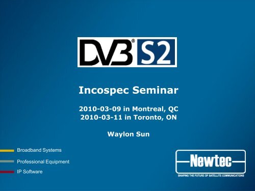
<strong><strong>Inc</strong>ospec</strong> Seminar<br />
2010-03-09 in Montreal, QC<br />
2010-03-11 in Toronto, ON<br />
Waylon Sun<br />
Broadband Systems<br />
Professional Equipment<br />
IP Software
What is <strong>DVB</strong>-<strong>S2</strong><br />
• The second generation <strong>DVB</strong> standard for digital<br />
transmission over satellite to replace <strong>DVB</strong>-S & <strong>DVB</strong>-<br />
DSNG<br />
• Second generation framing structure, channel<br />
coding and modulation systems for Broadcasting,<br />
Interactive Services, News Gathering and other<br />
broadband satellite applications<br />
• Draft released in 2004-01<br />
• EN302307v1.1.1 in 2005-03<br />
• EN302307v1.1.2 in 2006-06<br />
• EN302307v1.2.1 in 2009-08<br />
2
<strong>DVB</strong>-<strong>S2</strong> Efficiency Compared to <strong>DVB</strong>-S/DSNG<br />
18 dB<br />
11 dB<br />
3
<strong>DVB</strong>-<strong>S2</strong> Outperforming <strong>DVB</strong>-S<br />
Up to 2.5 dB<br />
less power needed<br />
4
<strong>DVB</strong>-<strong>S2</strong> Outperforming <strong>DVB</strong>-S<br />
Up to 30%<br />
Bandwidth saving<br />
5
<strong>DVB</strong>-<strong>S2</strong> Outperforming <strong>DVB</strong>-S<br />
Alberto Morello (Director Research RAI):<br />
“<strong>DVB</strong>-<strong>S2</strong> is the last standard”<br />
Less than 1dB from<br />
the theoretical limit<br />
6
The Gain of <strong>DVB</strong>-<strong>S2</strong><br />
• Much better spectral efficiency than <strong>DVB</strong>-S<br />
– Up to 40% bandwidth saving (30% from better<br />
coding and 10% from smaller roll-off factor) or up to<br />
2.5 dB margin gain<br />
– Less than 1 dB away from the Shannon limit<br />
• New modulation schemes (16APSK and 32APSK)<br />
• More roll-off factors (20, 25 and 35%)<br />
• New features<br />
– Support of multiple streams on a single carrier<br />
– Introduction of variable and adaptive coding and<br />
modulation<br />
– Introduction of generic mode input<br />
7
The Gain of <strong>DVB</strong>-<strong>S2</strong><br />
• New Forward Error Correction codes<br />
– LDPC (Low Density Parity Check) replaces Viterbi inner<br />
coding<br />
– BCH (Bose-Chaudhuri-Hocquenghem) replaces Reed<br />
Solomon outer coding<br />
– LDPC codes have resulted in FEC solutions that perform<br />
even closer to the Shannon Limit<br />
– LDPC was invented in 1962 by Dr. Gallager and<br />
rediscovered in mid-1990s when working with TCC<br />
(Turbo Convolutional Code).<br />
– Actual implementation of LDPC only became possible<br />
with ASIC technology (chip area
The Gain of <strong>DVB</strong>-<strong>S2</strong><br />
• LDPC uses very big block size (16200 and 64800 bits)<br />
– less fragmentation and then less overhead<br />
– large frame size means more delay<br />
– Short frames is less performing than Normal frames<br />
(about 0.3 dB) but with 1/4 of the delay<br />
• More inner code rates: 1/4, 1/3, 2/5, 1/2, 3/5, 2/3, 3/4,<br />
4/5, 5/6, 8/9, 9/10<br />
• APSK allows satellite link operation closer to saturation<br />
of the transponder. This is much better than QAM.<br />
9
10<br />
<strong>DVB</strong>-<strong>S2</strong> vs. <strong>DVB</strong>-S
Baseband Frame/FECFRAME<br />
H<br />
DATAFIELD<br />
Padding<br />
Baseband Frame (K bch )<br />
BBFRAME BCHFEC LDPCFEC<br />
FECFRAME (n ldpc )<br />
• FECFRAME have a fixed length<br />
– Normal FECFRAME: 64800 bits<br />
– Short FECFRAME: 16200 bits<br />
• Baseband Frame: Variable length, depening on the FEC<br />
11
Baseband Frame<br />
Baseband Frame (K bch )<br />
H<br />
DATAFIELD<br />
Padding<br />
80 bit Data Field Length K bch - DFL - 80<br />
MATYPE UPL DFL SYNC SYNCD CRC8<br />
MATYPE 1<br />
-TS/GS<br />
-SIS/MIS<br />
-CCM/ACM<br />
-ISSYI<br />
-NPD<br />
-RO<br />
MATYPE 2<br />
-ISI (MIS)<br />
-Reserved<br />
(SIS)<br />
User Packet<br />
Length<br />
-Continuous<br />
(0x0000)<br />
-Packetized<br />
(length in<br />
bits)<br />
Data Field<br />
Length<br />
User<br />
Packet<br />
Sync<br />
byte<br />
Distance to<br />
first user<br />
packet.<br />
Continuous<br />
generic<br />
streams:<br />
0000<br />
CRC<br />
on<br />
first 9<br />
bytes<br />
of<br />
BBH<br />
12
13<br />
Mode Adaption Type
14<br />
Bit Mapping into Constellation
TWTA Friendly Modulation Schemes<br />
• 16QAM in <strong>DVB</strong> has limited use in operation<br />
– High carrier to noise levels required<br />
– High demands on linearity: large back-off, huge HPAs and<br />
antenna sizes<br />
– High demands on phase noise<br />
• 16APSK in <strong>DVB</strong>-<strong>S2</strong> is fully enabled<br />
– Lower carrier to noise levels required<br />
– Easier to decode by demodulator due to less different<br />
amplitude and phase levels<br />
– More resistant to phase noise<br />
– Availability of pilot<br />
15
16<br />
XFECFRAME/PLFRAME
PL Signaling<br />
PLH<br />
XFECFRAME<br />
PLH<br />
XFECFRAME<br />
PLH<br />
XFECFRAME<br />
PL FRAME<br />
• The PLHEADER is intended for receiver synchronization and<br />
physical layer signaling.<br />
• Physical Layer Header<br />
– SOF Field: Start of the Frame<br />
– MODCOD Field: Identifying the XFECFRAME modulation and<br />
FEC rate<br />
– TYPE Field: Identifying the FECFRAME length (normal/short)<br />
and the presence/absence of pilots (on/off)<br />
17
18<br />
MODCOD Table
More Choice of Roll-off Factors<br />
• New roll-off factor<br />
• Occupied BW of the modulated signal = symbolrate x (1 + a)<br />
35%<br />
25%<br />
20%<br />
a = roll-off factor<br />
<strong>DVB</strong>-S<br />
a = 35 %<br />
-3dB<br />
<strong>DVB</strong>-DSNG:<br />
a = 25 or 35 %<br />
(professional)<br />
-26dB<br />
<strong>DVB</strong>-<strong>S2</strong>:<br />
a = 20, 25 or 35%<br />
19
<strong>Inc</strong>rease of the Throughput by Reducing the Roll-off<br />
35%<br />
Higher symbolrate<br />
20%<br />
Same occupied bandwidth<br />
• <strong>DVB</strong>-<strong>S2</strong> roll-off allows for a higher symbol rate in the same<br />
leased bandwidth<br />
• Example for a 36 MHz transponder<br />
– <strong>DVB</strong> (35%) 26.7 Mbaud<br />
– <strong>DVB</strong>-DSNG (25%) 28.8 Mbaud<br />
– <strong>DVB</strong>-<strong>S2</strong> (20%) 30.0 Mbaud<br />
20
21<br />
Modulator Functional Diagram
CCM, VCM and ACM<br />
• In <strong>DVB</strong>-<strong>S2</strong> each BB frame can be encoded and modulated with<br />
its own set of parameters - on the same carrier!<br />
• CCM Constant Coding and Modulation<br />
– All frames use the same parameters<br />
– Mainly used in video broadcasting (simple, cheap demod ASIC<br />
chips)<br />
• VCM Variable Coding and Modulation<br />
– Different streams/services are coded with different parameters<br />
– IP trunking, primary video distribution<br />
• ACM Adaptive Coding and Modulation<br />
– Each frame in a stream is coded with its own set of parameters.<br />
Parameters are modified dynamically according to the reception<br />
conditions for each receiver<br />
– Will be the killer application if shaping is made dynamical<br />
22
<strong>DVB</strong>-<strong>S2</strong> Multi-Streams<br />
• A <strong>DVB</strong>-<strong>S2</strong> modulator can have several physical or logical inputs:<br />
TS input 1<br />
TS input 2<br />
IP input<br />
Input<br />
interfaces<br />
Mode and<br />
Stream<br />
Adaptation<br />
(including<br />
padding)<br />
BB frames<br />
(16 or 64Kb)<br />
Coding and<br />
modulation<br />
Insertion of<br />
dummy PL<br />
frames<br />
Dummy PL frame<br />
PL frames<br />
• The data of each input is processed in separated BB frames.<br />
• The BB frames are time-multiplexed at the Physical Layer on the<br />
same carrier (allows for a big forward carrier)<br />
• Demodulators can decode individual streams based on ISI<br />
independently from the other streams<br />
• Each stream can be modulated with its own set of parameters<br />
(VCM and ACM)<br />
• No need for TS multiplexer with significant saving of overhead.<br />
23
Eb/No vs. Es/No<br />
• In <strong>DVB</strong>-S, the performance of a demodulator for a certain<br />
modcod is expressed in Eb/No (energy per bit over the<br />
normalised noise).<br />
• In <strong>DVB</strong>-<strong>S2</strong>, Es/No is used (Energy per symbol over the<br />
normalised noise)<br />
• In case of VCM/ACM operation, there is no constant bits per<br />
symbol over <strong>DVB</strong>-<strong>S2</strong> carrier<br />
• In case of CCM, Es/No = Eb/No + 10 log (η)<br />
– where the η is the spectral efficiency for the selected<br />
modcod.<br />
– Spectral efficiency is the number of bits per symbol<br />
– Spectral efficiency is based the MODCOD, Frame Size, Pilot<br />
On/Off, and Padding On/Off<br />
24
25<br />
Spectral Efficiency_MPEG (No Encapsulation)
26<br />
<strong>DVB</strong>-<strong>S2</strong> Application Drivers
<strong>DVB</strong>-<strong>S2</strong> 8PSK 2/3 vs. <strong>DVB</strong>-S QPSK 3/4<br />
• <strong>DVB</strong>-S: QPSK 3/4, 29.27 Msps, 35%<br />
• <strong>DVB</strong>-<strong>S2</strong>: 8PSK 2/3, 30.0 Msps, 20%, pilot present<br />
• We can fully push the <strong>DVB</strong>-<strong>S2</strong> MODCOD to 8PSK 2/3 to<br />
maximize throughput.<br />
• The data rate is increased by 18.4199 Mbps, that is<br />
45.54% comparing with <strong>DVB</strong>-S.<br />
<strong>DVB</strong>-S QPSK 3/4 <strong>DVB</strong>-<strong>S2</strong> 8PSK 2/3<br />
Es/No=7.26 dB<br />
C/No=82.03 dB-Hz<br />
OB=39.514 MHz<br />
Data Rate=40.4511 Mbps<br />
Es/No=7.10 dB<br />
C/No=81.87 dB-Hz<br />
OB=36.000 MHz<br />
Data Rate=58.0710 Mbps<br />
27
28<br />
Newtec <strong>DVB</strong>-<strong>S2</strong> Calculator
Generic Mode<br />
• In <strong>DVB</strong>-S the data format was exclusively the MPEG<br />
Transport Stream (TS)<br />
• The size of the MPEG transport stream packet (188 bytes)<br />
was optimised for the Reed Solomon error correction<br />
code, which is no longer used by <strong>DVB</strong>-<strong>S2</strong><br />
<strong>DVB</strong>-<strong>S2</strong> introduces a new Generic Mode for<br />
• Generic Continuous Stream and Packetized Stream<br />
For the Generic Mode<br />
• It is compatible with any type of data (IP, ATM,…)<br />
• It doesn’t need transport stream overhead (2%)<br />
• The efficiency gain for IP could be more than 4%<br />
29
Generic Stream Encapsulation (GSE)<br />
• <strong>DVB</strong>-<strong>S2</strong> does not define an encapsulation mechanism for IP<br />
data such as MPE as in <strong>DVB</strong>-S.<br />
• It is being studied by the standardization group (TM-GBS)<br />
• 2 proposals were presented: EDGE (ESA) and GULE (IETF)<br />
• They were merged and enhanced to create the GSE for the<br />
Generic Mode<br />
• The GSE protocol has been devised as an adaptation layer to<br />
provide network layer packet encapsulation and<br />
fragmentation functions over the generic stream of the <strong>DVB</strong>-<br />
<strong>S2</strong> standard.<br />
• ETSI TS102606V1.1.1 in 2007-10_protocol<br />
• ETSI TS102717V1.1.1 in 2009-06_implementation guidelines<br />
30
eXtended Performance Encapsulation (Newtec Proprietary)<br />
• Propriety protocol based on GULE<br />
– Data packets are encapsulated with a 4 or 10 byte header<br />
• 4 Byte header: Single Destination Mode<br />
• 10 Byte header: Multi-destination Mode<br />
– Optional CRC (4 bytes)<br />
XPE Packet: Sub-Network Data Unit (SNDU)<br />
D Length Type Destination address Data CRC<br />
2 Bytes 2 Bytes 6 Bytes 4 Bytes<br />
Destination Address (Airmac)<br />
Checksum<br />
Data type (IP, Ethernet,...)<br />
Field Length (15 bits)<br />
Destination address present (1 bit)<br />
31
eXtended Performance Encapsulation (Newtec Proprietary)<br />
• Generic Stream Header<br />
Payload Pointer Reserved CRC<br />
2 Bytes<br />
1 Byte 1 Byte<br />
Points to the first XPE packet<br />
Checksum<br />
32
eXtended Performance Encapsulation (Newtec Proprietary)<br />
• Generic Stream<br />
– XPE packets are put directly into Baseband frame<br />
33
Gigabit Ethernet Interface: NTC/7015<br />
• <strong>DVB</strong>-<strong>S2</strong> is optimized for both video and IP<br />
• Newtec offers a unique GbE interface that takes full advantage of all the<br />
feature that <strong>DVB</strong>-<strong>S2</strong> has to offer<br />
M&C<br />
2 ASI<br />
in/out<br />
1 internal Baseband<br />
Frame interface for<br />
mod/demod board<br />
2 GbE<br />
in/out<br />
M&C<br />
1 internal Baseband Frame Interface for<br />
Modem or dual demod<br />
other interface board to increase ASI ports<br />
<strong>DVB</strong>-<strong>S2</strong> modulator or demodulator or modem<br />
34
35<br />
GbE Processing Modes
36<br />
Pilots
Comparing <strong>DVB</strong>-S to <strong>DVB</strong>-<strong>S2</strong><br />
<strong>DVB</strong>-S<br />
<strong>DVB</strong>-<strong>S2</strong><br />
• BER 1E-7 after R/S (< 20 MBaud)<br />
• 1.3824 bit/Hz<br />
• PER 1E-5 188-byte (~BER 5E-8)<br />
• 1.4875 bit/Hz<br />
37
Comparing <strong>DVB</strong>-S to <strong>DVB</strong>-<strong>S2</strong><br />
<strong>DVB</strong>-<strong>S2</strong><br />
<strong>DVB</strong>-<strong>S2</strong><br />
• PER 1E-5 188-byte (~BER 5E-8)<br />
• 1.7665 bit/Hz<br />
• PER 1E-5 188-byte (~BER 5E-8)<br />
• 1.9806 bit/Hz<br />
38
A New Parameter: Pilot<br />
<strong>DVB</strong>-<strong>S2</strong> Challenge:<br />
• Near Shannon performance<br />
• Maintain carrier recovery under phase<br />
noise of LNB and tuner<br />
<strong>DVB</strong> Requirement:<br />
• Customers with existing antena/LNB<br />
should only change their set-top box to<br />
migrate from <strong>DVB</strong>-S to <strong>DVB</strong>-<strong>S2</strong><br />
Pilot:<br />
• Each pilot shall be an un-modulated<br />
symbol, identified by I = (1/√2), Q =<br />
(1/√2).<br />
•Subject to the same thermal/phase noise<br />
as any other symbols, it helps the<br />
demodulator in carrier recovery and<br />
receiver synchronization<br />
39
When to Use Pilots: Newtec Demodulator AZ910<br />
• Newtec AZ910 demodulator<br />
– Type A: Can be used for all baud rates<br />
– Type B: Baudrates >5 MBaud for QPSK and 8PSK<br />
• Performance figures under QPSK 1/3, 8PSK 3/5 2/3, and<br />
16APSK 2/3 3/4 or symbol rates below 3 MBaud are<br />
measured with pilots on<br />
40
Pilots: Generic Recommendations<br />
• Need for Pilots increases with:<br />
– Higher modulation schemes: 16APSK and 32APSK<br />
– Low code rates: 1/4, 1/3, 2/5, 1/2 and 3/5 for<br />
QPSK; 3/5, 2/3, 3/4 and 5/6 for 8PSK<br />
– Low symbol rates:
42<br />
Short and Normal Frame
Short Frames – Normal Frames (Comparative)<br />
Short Frame<br />
Normal Frames<br />
Performance - +<br />
(average 0.3 dB better)<br />
Spectral Efficiency - +<br />
Delay<br />
+<br />
-<br />
(modulation - demodulation) (only 25% of Normal Frames)<br />
Broadcast Not supported Mandatory<br />
• Recommendations:<br />
– Short frames: Only for time critical data applications<br />
– Broadcast: Normal Frames are mandatory<br />
– ACM/VCM: Do not mix short and normal frames<br />
43
Short Frames – Normal Frames (Delay Estimation)<br />
• Modulator delay:<br />
– 2 frames<br />
• Demodulator<br />
– 3 frames<br />
• Modulation–Demodulation Delay Calculation<br />
– Delay=(#frames x [frame-size] x spectral efficiency)/(mxbitrate)<br />
• Example: 256kbit/s, 8PSK 2/3, Pilots on, Short frames<br />
# frames: 5<br />
Frame-size: 16200 bits<br />
Spectral efficiency: 1.880672 bit/Hz<br />
m = 3 (8PSK)<br />
bitrate: 256000 bit/s<br />
Delay = 0.198s = 198 ms<br />
44
Pre-Distortion<br />
&<br />
Equalization<br />
45
Equalink TM : an enabler for 32APSK<br />
• Due to the lower carrier-to-noise levels required in <strong>DVB</strong>-<br />
<strong>S2</strong>, higher modulation schemes such as 32APSK<br />
become possible<br />
• Newtec’s unique Equalink TM is an embedded solution for<br />
predistortion in the modulator<br />
Amplitude compression<br />
Phase distortion<br />
Decoded signal without predistortion<br />
Decoded signal after enabling Equalink in the modulator<br />
46
Pre-Distortion and Equalization: The origin<br />
Linear Distortion – IMUX Filters<br />
Non-Linear Distortion: Amplifiers<br />
Input<br />
Filter/TX,RX chain<br />
Output<br />
Input<br />
Amplifier<br />
Output<br />
dB<br />
dB<br />
OBO<br />
AM-AM<br />
φ<br />
Freq<br />
Phase<br />
IBO<br />
dB<br />
msec<br />
Freq<br />
Group Delay<br />
time<br />
φ<br />
AM-PM<br />
Freq<br />
dB<br />
Impact: Received signals are distorted - degradation of the bit error rate<br />
Linear : Superposition principle holds – Characteristics are independent of the applied amplitude (Filters)<br />
Non-Linear : Characteristics are changing with the input amplitude (amplifier working close to saturation)<br />
47
Pre-Distortion and Equalization<br />
• Linear predistortion and Equalization<br />
– What: Compensates for amplitude and group-delay<br />
impairments in the transmission channel<br />
– Where:<br />
• Modulator: Linear predistortion (requires knowledge of amplitude<br />
and group delay characteristics of the transmission channel,<br />
operating parameters)<br />
• Demodulator: Adaptive Equalization (embedded. The operator<br />
just needs to enable/disable)<br />
• Non linear predistortion<br />
– What: Compensates for compression and phase rotation<br />
caused by non-linearity of amplifiers and clustering caused<br />
by filters.<br />
– Where:<br />
• Modulator: Non-linear predistortion (requires knowlegde of<br />
transponder AM-AM and AM-PM characteristics)<br />
48
Performance Degradation due to Non-Linearity (1)<br />
Non-linear Channel performance<br />
OBO /<br />
Degradation<br />
(dB)<br />
Optimal working<br />
point<br />
OBO CW<br />
OBO MOD<br />
QEF Es/No<br />
degradation<br />
Total<br />
degradation<br />
IBO (dB)<br />
49
Performance Degradation due to Non-Linearity (2)<br />
Non-linear Channel performance<br />
With non-linear predistortion<br />
OBO /<br />
Degradation<br />
(dB)<br />
Optimal working<br />
point<br />
OBO CW<br />
OBO MOD<br />
QEF Es/No<br />
degradation<br />
Total<br />
degradation<br />
IBO (dB)<br />
50
51<br />
Noise and Distortion Estimator<br />
NoDE
NoDE: Noise and Distortion Estimator<br />
True noise link margin<br />
<strong>Inc</strong>orrect link margin<br />
Effect of distortion<br />
So distortion effectively increases the Es/No<br />
needed for QEF reception.<br />
By correcting this Es/No by adding the degradation<br />
the true noise margin is obtained<br />
52
NoDE: Finding the Optimum Operating Point<br />
../Demodulator/Monitor/ModCodStats/Demodulator <strong>S2</strong> statistics<br />
• Modulation and FEC<br />
• Frame type (normal/short)<br />
• Pilots (on/off)<br />
• BB frame count (number of decoded baseband frames)<br />
• Uncor frame count (number of uncorrected frames)<br />
• Channel Quality Estimation<br />
• C/D Estimation<br />
• Link Margin Estimation (LME)<br />
53
Thank you for your attention<br />
waylon.sun@newtec.eu<br />
Broadband Systems<br />
Professional Equipment<br />
IP Software