SMART DIFFERENTIAL PRESSURE TRANSMITTER PYRD-2000ALW
SMART DIFFERENTIAL PRESSURE TRANSMITTER PYRD-2000ALW
SMART DIFFERENTIAL PRESSURE TRANSMITTER PYRD-2000ALW

You also want an ePaper? Increase the reach of your titles
YUMPU automatically turns print PDFs into web optimized ePapers that Google loves.
PD vers<br />
<strong>SMART</strong> <strong>DIFFERENTIAL</strong><br />
<strong>PRESSURE</strong> <strong>TRANSMITTER</strong><br />
<strong>PYRD</strong>-<strong>2000ALW</strong><br />
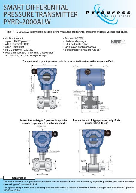
The <strong>PYRD</strong>-<strong>2000ALW</strong> transmitter is suitable for the measuring of differential pressures of gases, vapours and liquids.<br />
• 4 - 20 mA output<br />
• signal + HART protocol<br />
• ATEX Intrinsically Safe<br />
• ATEX Flameproof<br />
• PED Conformity (97/23/EC)<br />
• Programmable zero range, shift, unit selection •<br />
• and damping ratio with local panel keys<br />
• Accuracy 0.075%<br />
• Hastelloy diaphragm<br />
• SIL 2 certificate option<br />
• Gold plated diaphragm option<br />
• Static pressure limit up to 420 Bar<br />
Transmitter with type C process body to be mounted together with a valve manifold.<br />
SMAR<br />
The APCE-2000 pressure trans<br />
of gases, vapours and liquids.<br />
a diaphragm and by specially se<br />
7/16” STD<br />
or M10<br />
APCE-20<br />
Transmitter with type C process body to be<br />
mounted together with a valve manifold.<br />
Transmitter with P type process body. Static<br />
pressure limit 40 Bar.<br />
Construction<br />
Economical version<br />
- housing 304ss<br />
- protection IP65<br />
- electrical connecti<br />
- the electronics enc<br />
a protective silicon g<br />
-ATEX Intrinsic safe<br />
II 1/2G<br />
Ga/Gb Exia IIC T4/T5<br />
I M1 Ex ia I<br />
II 1D Ex iaD 20 T110°<br />
The active element is a piezoresistant silicon sensor separated from the medium by separating diaphragms and a specially<br />
selected type of manometric fluid.<br />
The special design of the active sensing element ensure that it is able to withstand pressure surges and overloads of up up to<br />
250/320/420 Bar.
<strong>PYRD</strong>-<strong>2000ALW</strong> <strong>SMART</strong> <strong>PRESSURE</strong> <strong>TRANSMITTER</strong><br />
Communication, configuration and installation<br />
EX<br />
EX<br />
ATEX Intrinsic safety II 1/2<br />
ATEX Explosion – proof<br />
II 1/2G Exia/d IIC T6/ T5<br />
II 1/2D ExiaD 20/tD A21 T85<br />
The casing is of epoxy painted cast aluminium alloy or 316 stainless steel, degree of protection Version IP66/IP67. APR-2000ALE The design<br />
of the casing enables the use of a local display, rotation of the display by 90°, rotation 0…20 of the mA, casing 0…5 by mA, 0–355° 4…20 mA<br />
relative to the sensor, and a choice of cable direction.<br />
protocol<br />
Possibilities of the of the adjus<br />
of the measuring range accord<br />
the display panel keys<br />
Configurable display (LCD) 3½<br />
• 4 - 20 mA output signal + HART protocol or digital temperature Profibus range PA signal –40…+85°C<br />
No EEx or Profibus PA<br />
• Local push buttons for adjusting both zero and span, measuring range,<br />
• units etc with the display panel keys<br />
Communication and<br />
• Configurable display 5 digits with illumination The (working communication temperature standard for<br />
• range –40 to +85°C)<br />
the transmitter is the Hart protoco<br />
• ATEX Intrinsic safety EX II 1/2G Exia IIC T4/T5 Communication with the transmitt<br />
– aKAP-03 communicator,<br />
– some other Hart type communi<br />
• ATEX Flameproof EX II 1/2G Exia/d IIC T6/T5<br />
– a PC using an RS-Hart co<br />
II 1/2D Exia/d 20/tD A21<br />
configuration<br />
T85/T100<br />
software.<br />
Installation<br />
(*) .eddl files available on<br />
www.ap<br />
The transmitter with type P process body can be installed<br />
directly on the installation. A universal mounting bracket is<br />
available for mounting the transmitter on a 2” pipe (AL or ALS<br />
mounting bracket). When the pressure of steam or other hot<br />
media is measured, a siphon or impulse line should be used.<br />
The C type body connections can be fitted directly to a 3 or 5<br />
way manifold valve (or be supplied with one fitted - see type<br />
VM manifolds on seperate literature).<br />
If not fitted with an integral manifold the transmitter can be<br />
mounted on a wall or similar flat surface, or a 2” pipe using a<br />
C-2” mounting bracket.<br />
For applications where the medium is aggressive to the<br />
standard wetted parts the transmitter can be supplied with<br />
suitable diaphragm seals either direct connected or via st.<br />
steel capillary.<br />
For hygienic (e.g. food industry) applications it can be<br />
supplied fitted with suitable hygiene seals.<br />
For these options see separate literature or contact Pyropress<br />
sales office.<br />
Communication and configuration<br />
The communication standard for data interchange with<br />
the transmitter is Hart protocol. Communication with the<br />
transmitter via one of the following:<br />
– a KAP-03 communicator<br />
– industry standard Hart type communicators<br />
– a PC using an RS-Hart converter and Raport-02<br />
configuration software<br />
Electrical diagrams for <strong>PYRD</strong>-<br />
<strong>2000ALW</strong> with HART protocol<br />
Milliammeter<br />
Version: APR-<strong>2000ALW</strong><br />
mA<br />
TEST<br />
4÷20<br />
mA<br />
Power supply<br />
SIGNAL<br />
Transmitter 20 <br />
Electrical diagram<br />
RS-HART converter<br />
or communicator<br />
TEST<br />
Jumper<br />
Millia<br />
m
– conversion characteristic (inversion, Error due touser’s supplynon-<br />
linear characteristic);<br />
Electrical parameters<br />
voltagechanges 0.002% (FSO)<br />
G Ex ia IIC T4/T5<br />
read the currently measuredPower pressure supply value of<br />
Electrical<br />
the<br />
parameters<br />
12...55 VDC (Ex ia13,5...28<br />
<strong>PYRD</strong>-<strong>2000ALW</strong> <strong>SMART</strong> output current <strong>PRESSURE</strong> and the percentage<br />
Power <strong>TRANSMITTER</strong><br />
output<br />
supply<br />
control level;<br />
12...55 VDC (Ex ia13,5...28<br />
(Exd 13,5…4<br />
(Exd 13,5…4<br />
force anoutput current with aset<br />
Technical Data<br />
Additional value;<br />
/T100<br />
voltage drop<br />
calibrate the transmitter in relation Additional<br />
when display to amodel voltage<br />
illumination pressure.<br />
when display illumination switched on 3V<br />
drop<br />
switched on 3V<br />
Measuring ranges Output signal<br />
4...20mA, two wire transmiss<br />
Installation Output signal<br />
4...20mA, two wire transmiss<br />
Overpressure limit/ static<br />
No. Nominal measuringThe range(FSO) transmitter withMinimum P typesetprocess range connection Rangeability is not<br />
pressure limit<br />
, output signal + HART<br />
19 1 0 to 0...16 Bar bar (0...1,6Mpa)<br />
heavy, to 1.6 MPa)<br />
so it can1.6 befitted<br />
1,6 Bar bar<br />
directly<br />
(160kPa) onto<br />
kPa)<br />
impulse lines.<br />
10:1<br />
For<br />
<br />
R[<br />
Usup[V]<br />
12V<br />
2 0...2,5 bar (0...250kPa) 0,25 bar (25kPa)<br />
Loadresistance<br />
10:1<br />
250 bar /(320, 420 bar<br />
14 0 to 0.25 Bar fitting to inany desired 0.25 Bar position werecommend an universal Bar<br />
Bar<br />
R[ ]<br />
<br />
option) 0.85<br />
ting both start 113 and 0 end to 0...1 1 Bar bar (0...100kPa) Aplisens to kPa) mounting 70 mBar 70mbar bracket for (7kPa) 2" pipe (AL mounting<br />
14:1<br />
(400,02A<br />
Bar bar for Ptype<br />
ing to set pressure 08 4 0 with to 0...0,25 0.25 Bar bar (0...25 bracket, to 100 kPa) kPa) see page 1065).<br />
mBar 10mbar (1kPa) 25:1<br />
-15Vwhendisplay Process connection)<br />
illuminationswitched on<br />
455 -100…100mbar to mBar (-10…10kPa) to 4 mBar 4mbar (0,4kPa) (0.4 kPa)<br />
50:1<br />
(250 Bar bar for PED version)<br />
42 6 -5-5...70mbar to mBar (-0,5...7kPa) The (-0.5 to version 7 kPa) with4 mBar C4mbar type process (0,4kPa) (0.4 kPa) connections<br />
Resistance 18:1 can<br />
required be<br />
forcommunication 250...1100<br />
digits (working<br />
477 -0.5 -0,5...0,5 to 0.5 Bar bar (-50...50kPa) fitted to directly kPa) to a3-or5-valve 0.10,1 Bar bar ( 10kPa) manifold. (10 kPa) Werecommend<br />
10:1<br />
)<br />
8 factory-mounted transmitters with VMtype valve manifold<br />
44 -20-20...20 to mBar mbar (-2...2kPa) to 2 kPa) 2 mBar 2mbar (0,2kPa) (0.2 kPa) 20:1 20 bar Bar<br />
(page 62). Atransmitter without avalve manifold can be<br />
fitted in any positionTechnical on a2" pipe data or on awall using the C-<br />
Accuracy depending<br />
configuration Operating parameters<br />
Metrological2" parameters mounting bracket (page 65).<br />
Accuracy on Materials the depending set range<br />
on the set range<br />
Accuracy<br />
±0.075% of calibrated range<br />
Accuracy ≤ ±0.075% of the calibrated range<br />
Wetted parts: type Pprocess connection 316Lss<br />
data interchange with<br />
When the special process connections are required for<br />
±0.1% of calibrated range<br />
(≤ ±0.1% for ranges 42 and 44)<br />
type Cprocess Accuracy connection 316ss<br />
l.<br />
the measurement of specific media levels inclosed tanks<br />
Long term stability<br />
accuracy for 3years<br />
Long-term (for thestability<br />
nominal measuring ≤ accuracy range) (e.g. Diaphragms:<br />
Hastelloy C276, Au<br />
for inthe 3 years sugar and chemical industries) the transmitter<br />
(for the nominal measuring range)<br />
Thermal error<br />
±0.08% (FSO) /10°C<br />
Casing:<br />
1<br />
er is Aluminium<br />
Thermal<br />
carried out<br />
max. error<br />
with:<br />
is fitted with an Aplisens diaphragm seal. Sets of differential<br />
(FSO) compensation pressure / 10°Ctransmitters temperature with diaphragm seals Option: 316SS<br />
±0.3% (FSO) < in±0.08% the whole<br />
range<br />
max. ±0.3% (FSO) are described<br />
indetail inthe further part-NACE of theMR–01–75compatible<br />
catalogue.<br />
(in the whole compensation temp range) 0<br />
cators (*)<br />
Set range<br />
Thermal compensation range -25…80°C<br />
nverter Thermal andcompensation Raport-02 range -25 to 80°C<br />
Operating conditions<br />
Zero shift error for static pressure<br />
Operating temperature range 10(ambient 30 temp.) -25...85°C 100<br />
[%]<br />
Zero shift 0.01% error (FSO) for /10 static bar forpressure<br />
range 3, 4<br />
EEx version -25…80°C<br />
0.01% (FSO)<br />
0.03%<br />
/(FSO) 10 Bar<br />
/10<br />
for<br />
bar for<br />
ranges 5,<br />
116,<br />
and 8<br />
0 – error for nominal measuring<br />
0.03% (FSO)<br />
0.08%<br />
/(FSO) 10 Bar<br />
/10<br />
for<br />
bar for ranges45 1,2,7,8<br />
Medium temperature range<br />
-25...120°C<br />
and 42<br />
range (0...100% FSO)<br />
Zeroing the transmitter inconditions ofstatic pressure can eliminate<br />
(FSO) this error. / 10 Bar for ranges 19, 14, 47 and 44<br />
<br />
1<br />
– error for range 0...10% FSO<br />
or diaphragm seals<br />
over 120°C –measurement with the use of impulse line<br />
0.05%<br />
lisens.com<br />
(Zeroing Additional this transmitter electronic under damping regular static pressure 0…60 s can eliminate this error)<br />
up to 100C PED version<br />
<br />
1 = 2×<br />
<br />
0<br />
Error due to supply voltage changes 0.002% (FSO) /V<br />
Additional electronic damping<br />
0 to 60 s CAUTION: the medium must Numerical not be allowed error tofreeze values inthe are given impulse<br />
line orclose to the process the technical connection data of the under transmitter operating metrological<br />
Error due to supply Electrical voltage changes parameters 0.002% (FSO) / V<br />
parameters<br />
in<br />
Special versions, certificates<br />
s for transmitters with HART protocol<br />
Power supply 12...55 VDC (Ex ia 13,5...28 V)<br />
<br />
Special versions, certificates<br />
Diaphragms: Hastelloy C-276, Au<br />
Casing: Aluminium<br />
Option: 316 Stainless steel<br />
NACE MR - 01 - 75 compatible<br />
(Ex d13,5…45V)<br />
Electrical parameters<br />
Ex ia –Atex Intrinsic safety<br />
Additional voltage drop when<br />
<br />
6 Ex d –Atex explosion proof<br />
Exia Version: – display ATEX APR-2000ALE<br />
illumination Intrinsically switched safe on 3V<br />
Version: PED Power APR-2000ALE<br />
–European supply Pressure 12 to Equipment 55V DC Directive (Exia N 13.5 97/23/EC to 28V)<br />
Exd with<br />
Output<br />
– ATEX 4…20mA<br />
signal<br />
Flameproof output signal<br />
4...20 mA, two wire transmission<br />
with 0…5 or (Exd 13.5 to 45V)<br />
APC-2000ALE: 0…20 or0…5, 4…20 [mA]<br />
<br />
0…20mA<br />
320 bar -static<br />
output<br />
pressure<br />
signal<br />
limit: 320 bar (not for PED version)<br />
<br />
320 Bar – Static pressure limit: U 320 Bar (not PED version)<br />
Additional voltage drop when display illumination is<br />
sup[V]<br />
12V<br />
Loadresistance R[ ]<br />
<br />
RS-HART<br />
0.85<br />
converter<br />
420 bar -static pressure limit: 420 bar (not for PED version)<br />
0,02A or communicator<br />
Tlen<br />
switched<br />
–transmitter<br />
on<br />
designed<br />
3V<br />
for oxygen<br />
420 Bar – Static pressure limit: 420 Bar (not PED version)<br />
-15V Power when display supply illumination switched on<br />
Power Special Output supply range: signal -1,6…2bar RS-HART 4 to 20 converter mA, two wire transmission<br />
PED – Resistance European required Pressure for communication Equipment Directive 250...1100N° 97/23/EC<br />
or communicator<br />
-1,6…16bar U sup<br />
[V] - 12V*<br />
Load resistance R [Ω] ≤ .<br />
OXY – Transmitter designed for oxygen<br />
0.85<br />
4÷20<br />
Thermal compensation from -40°C 0.02A<br />
Special<br />
mA<br />
SIL2<br />
range – -1.6 to 2 Bar, -1.6 to 16 Bar<br />
*-15V – Functional when display Safety.According illumination toIEC 61508/61511 switched on<br />
mmeter<br />
Device with Declaration ofSIL2 for use insafety related applications<br />
Accuracy depending on the set range<br />
Thermal compensation down to -40°C<br />
Resistance up to SIL2 required for communication:<br />
0÷20<br />
MR 240 – Marine to 1100 Certificate Ω –DNV<br />
Accuracy<br />
SIL2 – Functional safety. According to IEC 61508/61511 0÷<br />
5<br />
SS – Housingmaterial –316ss<br />
Adevice with declaration of SIL2 for use in safety related mA<br />
1<br />
Au<br />
applications up to SIL2<br />
Operating – gold plated diaphragm, conditions<br />
only Ctype connection (range<br />
0<br />
no. 4)<br />
Set range<br />
ALW/SS – Housing material 316 Stainless steel<br />
Others Operating temperature<br />
10 30 100 [%]<br />
range (ambient temp.) -25 to 85°C<br />
CG – Gold plated diaphragm. (range no. 8 only and C type<br />
process body only) - Hydrogen<br />
0 – error for nominal measuring<br />
applications<br />
Ex version -25 to 80°C<br />
range (0...100% FSO)<br />
Process temperature range -25 to 120°C<br />
Materials 4 3 2 1<br />
1 – error for range 0...10% FSO 4 3 2 1<br />
1 = 2× 0<br />
Note: PED version -25 to 100°C<br />
Wetted parts: Type P<br />
Numerical<br />
process<br />
error<br />
body<br />
values<br />
316L<br />
are given<br />
Stainless steel<br />
the technical data under metrological<br />
Type C parameters process body 316 Stainless steel<br />
For processes over 120°C, impulse lines or diaphragm<br />
seals should be used.<br />
OUTPUT<br />
3 WIRE<br />
TEST<br />
2 WIRE<br />
TEST<br />
R0<br />
OUTPUT<br />
3 WIRE<br />
TEST<br />
2 WIRE<br />
TEST<br />
R0<br />
CAUTION: the medium must not be allowed to freeze in<br />
the impulse line or close to the process connection of the<br />
transmitter.
<strong>PYRD</strong>-<strong>2000ALW</strong> <strong>SMART</strong> <strong>PRESSURE</strong> <strong>TRANSMITTER</strong><br />
Ordering Procedure<br />
Model: <strong>PYRD</strong>-<strong>2000ALW</strong><br />
Description: Differential Pressure transmitter<br />
Certification<br />
Nominal<br />
Range Code<br />
-D .................................<br />
-IS ................................<br />
-SSIS ...........................<br />
-23............................<br />
-19 ...............................<br />
-14 ...............................<br />
-11 ...............................<br />
-08 ...............................<br />
-45 ...............................<br />
-42 ...............................<br />
-47 ...............................<br />
-44 ...............................<br />
Exd certification<br />
Exia certification<br />
Exia certification with stainless steel housing<br />
0 - 70 Bar<br />
0 - 16 Bar<br />
0 - 2.5 Bar<br />
0 - 1 Bar<br />
0 - 0.25 Bar<br />
-100 to +100 mBar<br />
-5 to +70 mBar<br />
-0.5 to +0.5 Bar<br />
-20 to +20 mBar (20 Bar max only)<br />
Range in relation to 4 -20mA<br />
Example: 0-10B = 0-10 Bar<br />
P = PSI K = KG/CM 2 MB = Mbar (other units available)<br />
Process<br />
Connection<br />
-P .................................<br />
-GB ..............................<br />
-N4 ...............................<br />
-GA ..............................<br />
-C .................................<br />
-CG ..............................<br />
-X .................................<br />
M20 X 1.5 Male with 12 dia hole - SS316 - 40 Bar max<br />
G1/2” Male with 4 dia hole - SS316 via adaptors - 40 Bar max<br />
1/4” NPT Female - SS316 via adaptors - 40 Bar max<br />
G1/4” Male - SS316 via adaptors - 40 Bar max<br />
Manifold flange, SS316 wetted parts with Hastelloy diaphragm<br />
with 2 x 1/4” NPT female process connections - 250 Bar max<br />
Manifold flange as above with gold plated diaphragm (range 08 only)<br />
Diaphragm seal<br />
Options<br />
List if more than one<br />
-OXY ............................<br />
-C32 .............................<br />
-C42 .............................<br />
-PED ............................<br />
-SIL ..............................<br />
-BCZ ............................<br />
-BCS ............................<br />
-AL ...............................<br />
-ALS ............................<br />
-BF ...............................<br />
-UL ...............................<br />
For oxygen service - Fluorolube filled (only available with “P”<br />
type process body)<br />
320 Bar option on “C” type process body<br />
420 Bar option on “C” type process body<br />
European Pressure Equipment Directive No 97/23/EC, Cat IV.<br />
Suitable for use within SIL2 systems<br />
2” pipe & wall mounting bracket for “C” type process body - zinc<br />
plated steel<br />
2” pipe & wall mounting bracket for “C” type process body -<br />
stainless steel<br />
2” pipe mounting universal bracket, zinc plated steel<br />
2” pipe mounting universal bracket, stainless steel<br />
25mm pipe mounting bracket for “P” type process body only<br />
1/2” NPT female entry<br />
Tel: +44 (0)1752 339866<br />
Email: sales@pyropress.com<br />
Web: www.pyropress.com<br />
Pyropress Engineering Company Ltd<br />
Bell Close, Plympton<br />
Plymouth, Devon, PL7 4JH<br />
United Kingdom