DRV - Biotech ortho
DRV - Biotech ortho
DRV - Biotech ortho

You also want an ePaper? Increase the reach of your titles
YUMPU automatically turns print PDFs into web optimized ePapers that Google loves.
<strong>DRV</strong><br />
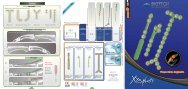
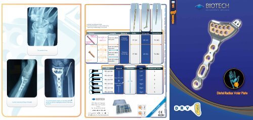
Pre-operative X-ray<br />
Implants are delivered sterile.<br />
The instrumentation is colour coded with a<br />
silicon ring corresponding to the screw<br />
Screws<br />
VENPS 24<br />
Epiphyseal<br />
screws<br />
VENPS 35<br />
Diaphyseal<br />
screws<br />
From VENPS 2410<br />
to<br />
VENPS 2428.<br />
From VENPS 3510<br />
to<br />
VENPS 3530.<br />
From VENPS 3514<br />
to<br />
VENPS 3518.<br />
From VENPS 3530<br />
to<br />
VENPS 3546.<br />
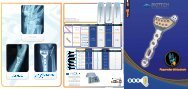
Plate<br />
PES 220 301<br />
PES 220 401<br />
PES 220 501<br />
PES 220 302<br />
Lengths<br />
From 10 to 28mm<br />
2mm pitch<br />
From 10 to 30mm<br />
2mm pitch<br />
From 14 to 18mm<br />
1mm pitch<br />
From 30 to 46mm<br />
4mm pitch<br />
PES 220 402<br />
Material<br />
R<br />
Drills<br />
Drill guides<br />
Screwdrivers<br />
Material Thickness Side Diaphyseal holes<br />
Peek Optima<br />
inserts<br />
Titanium<br />
Titanium<br />
Left<br />
Left<br />
Left<br />
Right<br />
Right<br />
illustrations for information<br />
Patents : Plates : Patent pending - USA 10/530.683. Europe 03 807 887 - Screws : Patent pending - PCT/FR05/02469 - 05 809 108 3 - France 04/105 8<br />
PES 220 502<br />
Right<br />
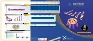
Distal Radius Volar Plate<br />
A perfect anatomical fitting of the plate<br />
The radiotransparent property of the Peek-Optima<br />
permits an optimum radiological control of the osteosynthesis.<br />
FP - 0204<strong>DRV</strong> - rev.01 - 02/2012 - EN
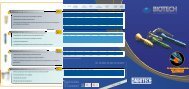
1. Temporary positioning<br />
Operative protocol of the <strong>DRV</strong> Plate<br />
4. Distal screws placement<br />
Technical variations.<br />
Proximal plate bending technique<br />
Volar Insicion, using Henry’s exposure of the distal part<br />
of the Radius.<br />
Selection of plate using trial either of 3, 4 or 5 hole plate.<br />
Drill (FT241) through the drill guide (GM240)<br />
Check placement with fluoroscope.<br />
Screw insertion using screw driver (TV240) and fluoroscopic control.<br />
If necessary, bend the plate using the special plate bending irons in the bending area.<br />
Place trial plate on reduced and stabilised fracture and<br />
fix with two 1.2mm K-wires.mm.<br />
2. Final plate placement<br />
Remove trial plate leaving K-wires in position.<br />
Place selected plate implant over K-wires and position.<br />
CAUTION: Place a screw in each fragment,<br />
combined with at least one internal and one<br />
external cuneate screw<br />
5. Final adjustment.<br />
Epiphyseal screw tightening (TV240).<br />
Oblong hole screw tightening (TV350)<br />
Additional diaphyseal screw insertion if needed.<br />
K-wire removal.<br />
Make sure that the bending irons and positioned on the<br />
metal part of the plate and not the section where the<br />
Peek-Optima inserts are positioned.<br />
bending area<br />
Using the drill guide (GM350), drill a pilot hole with noncannulated<br />
drill (FT351) in oblong screw hole.<br />
CAUTION : Do not bend the plate outside the bending area as this may dislodge<br />
the Peek-Optima inserts<br />
Styloid distal bending technique.<br />
3. Proximal screw placement<br />
Measure required screw length with depth gauge.<br />
Screw the first diaphyseal screw through<br />
the oblong hole (TV350).<br />
Option : Styloïdian fragments synthesis with a K-wire<br />
Styloidian K-wires integration<br />
Insert the K-wire (BR 120) into the distal part<br />
of the plate to bring together the eventual<br />
styloidian fragments.<br />
5 mm<br />
If necessary, bend the Styloid end of the plate using the special plate bending irons in<br />
the area where the furrow is marked.<br />
Over view<br />
CAUTION : At this stage do not lock the<br />
proximal screw in the oblong hole such<br />
to allow further adjustment if necessary<br />
Make sure that the bending<br />
irons are located on the<br />
metal part of the plate and<br />
not on the Peek-Optima<br />
inserts.<br />
Cut the K-wire 5 mm above the plate.<br />
Pull down the K-wire onto the plate with the wire<br />
bender ( TB120) so that it shows on the surface<br />
of the plate.<br />
Other option : use a staple.<br />
CAUTION : Do not bend the plate outside the marked<br />
bending area as you may dislodge the Peek-Optima<br />
inserts