Lightweight ExoAtmospheric Projectile (LEAP) - United States ...
Lightweight ExoAtmospheric Projectile (LEAP) - United States ...
Lightweight ExoAtmospheric Projectile (LEAP) - United States ...

You also want an ePaper? Increase the reach of your titles
YUMPU automatically turns print PDFs into web optimized ePapers that Google loves.
<strong>LEAP</strong> PROGRAM ENVIRONMENTAL ASSESSMENT<br />
1.0 DESCRIPTION OF PROPOSED ACTION AND ALTERNATIVES<br />
The National Environmental Policy Act (NEPA), the Council on Environmental Quality<br />
Regulations implementing NEP A ( 40 CFR 1500-1508), and the U.S. Department of Defense<br />
(DoD) Directive 6050.1 direct that DoD officials take into account environmental<br />
consequences when authorizing or approving major Federal actions. This environmental<br />
assessment (EA) presents an analysis of the environmental consequences of conducting<br />
activities in support of the <strong>Lightweight</strong> <strong>ExoAtmospheric</strong> <strong>Projectile</strong> (<strong>LEAP</strong>) Test Program.<br />
I<br />
Section 1.0 of this EA describes the purpose and need for the proposed action, the<br />
proposed action, and alternatives, including the no-action alternative. Section 2.0 describes<br />
the environment to be affected by the proposed action. Section 3.0 assesses the potential<br />
environmental consequences of the proposed activities on the environmental components<br />
identified in Section 2. H a particular activity bas the potential to have a significant effect<br />
on the environment, mitigation measures have been incorporated into the proposal to<br />
reduce the potential significant effects to insignificant levels. These mitigation measures<br />
will be implemented as part of the proposal.<br />
1.1 PURPOSE AND NEED FOR TilE PROPOSED ACTION<br />
As part of its responsibilities for developing a viable and effective Strategic Defense System<br />
(SDS), the Strategic Defense Initiative Organization (SDIO) must demonstrate the<br />
capability to acquire, track, and intercept targets from various trajectories at varying<br />
altitudes. The <strong>LEAP</strong> Test Program is an SDI experiment program being funded to<br />
demonstrate compliance with this requirement.<br />
The purpose of the <strong>LEAP</strong> Test Program is to design, develop, and demonstrate the<br />
capability of a miniaturized, lightweight projectile to intercept targets in the exoatmospheric<br />
1-1 .
egton. These tests are required so that the SDIO Director can make a decision concerning<br />
the effectiveness of these technologies ano &dr role in a strategic defP.~'i'!<br />
system.<br />
1.2 PROPOSED ACTION<br />
The proposed action is to design. develop, and demonstrate space test projectiles capable<br />
of intercepting targets in the exoatmosphere. The <strong>LEAP</strong> Test Program is funded to<br />
demonstrate compliance with this requirement. Activities required to support this program<br />
are execution of component/ assembly tests, pre-flight activities, and flight test activities.<br />
_-\dditionaily, construction oi test iacilities at Phillips Laboratory on Edwards Air Force Base<br />
\AFB), and modification oi launch facilities at Wake Island will be reqUlied.<br />
The following discussion is a brief description of the concept oi the <strong>LEAP</strong> technology<br />
program and a detailed description of the activities required to suppon the proposed action<br />
for these technologies. The proposed action also covers activities which include the<br />
manufacture of flight test articles unique to the experiments, and the operation of relevant<br />
facilities at the host installations.<br />
1.2.1 Background and Concept of the <strong>LEAP</strong> Test Program<br />
The <strong>LEAP</strong> projectile is a miniaturized projectile being designed by several program<br />
participants and integrated by SDIO for demonstration. Other interceptor technology<br />
programs, such as the Exoatmospheric Reentry Vehicle Interceptor Subsystem (ERIS), have<br />
demonstrated that a large interceptor vehicle is capable of intercepting targets in the<br />
exoatmosphere: however, the main objective of the <strong>LEAP</strong> Test Program is to demonstrate<br />
the possibility of interception by a lightweight, miniature vehicle.<br />
Two technological approaches to the development of <strong>LEAP</strong> technologies are simultaneously<br />
under investigation. The first approach is being coordinated by the U.S. Air Force through<br />
,;;e Phillips Llboratory, Edwards AFB. C:Jifornia. T:1e second is being coordinated bv the<br />
L".S . .
similar and both employ liquid hi-propellant engines for divert maneuvering. The liquid<br />
bipropellants used are hydrazine or monomethylhydrazi.ne as the fuel and nitrogen tetroxide<br />
as the oxidizer. They differ only in the avionics technology applied to the projectile's<br />
sensor, guidance, stabiliza:.ion., and control subsystems (SDI0/1NS, 1990).<br />
Execution of the <strong>LEAP</strong> Test Program will take place at the following facilities: Boeing<br />
Aerospace and Electronics, Seattle, Washington; Hughes Aircraft Company, Missile Systems<br />
Group, Canoga Park, California; Orbital Sciences Corporation, Space Data Division,<br />
Chandler, Arizona; Phillips Laboratory, Edwards AFB, California; White Sands Missile<br />
Range (WS1ffi.), New Mexico; U.S. Army Kwajalein Atoll (USAKA); and Wake Island.<br />
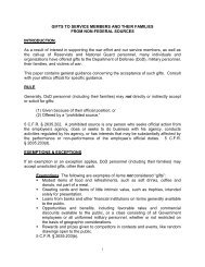
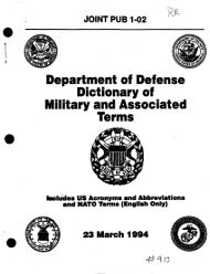
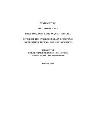
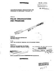
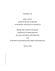
As currently configured, the <strong>LEAP</strong> Program will consist of ground tests, four test flights<br />
with rocket vehicles launched from White Sands Missile Range (WS1ffi.), New Mexico<br />
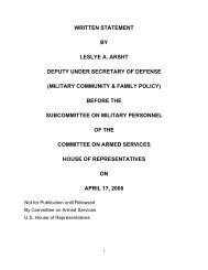
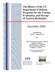
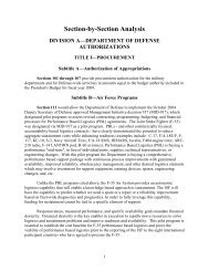
(Figures 1 and 2) and two test flights at U.S. Army Kwajalein Atoll (USAKA) (Figure 3)<br />
with the target launches from Wake Island (Figure 4).<br />
'<br />
I<br />
I'<br />
II<br />
Existing launch facilities (Launch Complex [LC 36] and Sulf Site at WS:MR, Meek Island<br />
at USAKA, and Wake Island) will be used at all locations. The launches proposed for<br />
USAKA will be examined in the context of existing environmental documentation.<br />
Specifically, the Environmental Impact Statement (EIS) for Proposed Actions at U.S . .
12.2.1 Phillips Laboratory<br />
Component/ Assembly and testing activities at Phillips Laboratory to support the <strong>LEAP</strong><br />
Program will require the modification of test facilities and construction of a new integration<br />
area.<br />
The proposed integration area would consist of a new 4,000 square foot enclosure, 80 feet<br />
long and 50 feet wide. The enclosure would contain a clean room for vehicle integration,<br />
work areas for electronics integration, and storage areas. No explosives storage or handling<br />
activities would occur in the new area.<br />
The new facility will be constructed adjacent to the existing control room (Building 8840).<br />
The area where the expansion will occur has previously been graded. Existing utilities will<br />
be used to provide water, power, and sewer services to the expanded structure.<br />
12.2.2 Wake Island<br />
Target launches at Wake Island will require the modification of some new facilities and the<br />
remodeling of selected existing facilities. Required modification activities are described<br />
herein.<br />
Existing facilities at Wake Island were constructed for the Starbird program for launches<br />
on a 62 o launch azimuth. LE."'...P target flights, which will launch on a 140 o launch azimuth,<br />
will use Starbird facilities (assessed in USASDC, 1987). These facilities will require<br />
modification to accommodate a different booster and launch azimuth.<br />
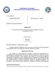
Figure 5 shows the principal airfield activity areas on Wake Island and the proposed<br />
locations of new activities. Additional land for the LEA!' launches will not be required<br />
because Starbird and existing base facilities will be modified to meet the programs'<br />
specificatjons. Mitigation measures for Starbird aCtivities on Wake Island have already·<br />
1-4
. .,<br />
I<br />
State of New Mexico<br />
)<br />
• Santa Fe<br />
White Sands<br />
Missile Range<br />
• Alamagordo<br />
Miles<br />
<strong>LEAP</strong> ENVIBONMENTAL ASSESSMENT<br />
NEW MEXICO AND<br />
WHITE SANDS<br />
- --MISSftE RANGE ..<br />
1-5 Figure 1
.I<br />
~<br />
N<br />
j<br />
I<br />
I<br />
I<br />
I<br />
I<br />
I<br />
I<br />
I<br />
I<br />
I<br />
I<br />
\<br />
\<br />
/<br />
WSMR<br />
I<br />
I<br />
I<br />
I<br />
I<br />
I<br />
I<br />
I<br />
I<br />
I<br />
I<br />
I<br />
I<br />
I<br />
I C<br />
I .Q<br />
I :!!<br />
! a:~ ,<br />
\ ""'"" Ul UJ<br />
I ~ $: ~<br />
... ....<br />
~.... (ij<br />
/
---<br />
Pacific Ocean<br />
EBADON-~.J'<br />
0<br />
0 • • •<br />
0 q<br />
' .<br />
"<br />
ROI·NAMUA --C;;J-t-ENNUGARRET<br />
4<br />
~l:;;-ENNUBIRR<br />
0
!--3o·N-- - -------t-------l---------r---------<br />
1 Pacific Ocean<br />
__ -------~------ ____ 1 __<br />
0<br />
.,.10<br />
PacJ 1c cean<br />
\<br />
San Francisco\<br />
_~:~--- _ ----------~~ --l::==:..:.~====-f====4====t==;3ow·NN:_ ---<br />
LsA<br />
~<br />
00 '<br />
f--I-15•N-~~~~-~------jr---<br />
BIKINI IS.<br />
Q.<br />
MARSHALL ISLANDS<br />
~iTnUKIS.<br />
• y<br />
C)<br />
a<br />
0<br />
PONAPE IS.<br />
"o<br />
c:i•<br />
KUSAIE IS.<br />
~ 0 ~
I<br />
) .<br />
J<br />
I<br />
been adopted (USASDC, 1987) or have been agreed upon by the Advisory Council on<br />
Historic Preservation (ACHP) and the U.S. Fish and Wildlife Service (USFWS). These<br />
measures were primarily motivated by the historic stature of Wake Island's role duriD.g<br />
World War II and the possible presence of protected species on the island and in its nearshore<br />
waters. The mitigation measures require the use of existing facilities where possible,<br />
minimum disturbance of the environment, limitation on human intrusion into certain<br />
undisturbed parts of Wake Island, and specific protection and monitoring activities to<br />
minimize disturbance to cultural resources and protected species. <strong>LEAP</strong> related activities<br />
at Wake Island are similar in scope to those of the Starbird program, and as such these<br />
mitigations are incorporated into the <strong>LEAP</strong> program to protect biological and cultural<br />
resources at Wake Island.<br />
The <strong>LEAP</strong> program activities will occur at eight facilities that were constructed, renovated,<br />
or provided for the Starbird Program: 1) Launch Pad 1; 2) the Missile Assembly Building<br />
(MAB); 3) the Launch Support Building (LSB); 4) the Missile Storage Building (MSB); 5)<br />
the Pyrotechnic Storage Building (PSB), launch control equipment at the Mobile Real Time<br />
System (MRTS) site, and the radar/telemetry sites. In addition, a Personnel Barrack will<br />
be renovated to house temporary personnel. All but the MSB, PSB, and MR TS will require<br />
modifications to support <strong>LEAP</strong>; however, these will be minor and will be conducted by<br />
the on-site operations contractor.<br />
The Missile Assembly Building will be modified for the <strong>LEAP</strong> target flights. A thru-wall<br />
air conditioning system, requiring a "lean to" for the mechanical room, \'lill be installed.<br />
In addition, the hibay louvers will be sealed, the bridge crane will be load tested and<br />
refurbished, and the battery room will be refurbished.<br />
Launch Pad 1 will be modified for <strong>LEAP</strong> use. These modifications result from the change<br />
from launches to the northeast (Starbird) to launches to the.southeast (<strong>LEAP</strong>). Conduits<br />
for control systems must be relocated due to the changed azimuth; therefore, cable trays<br />
and a launch equipment buildin~ (LE~) fo11ndation must be COIDitructed. In addition,<br />
--· ;<br />
.<br />
.<br />
1-9
. =-------<br />
BARICACkS,<br />
MESS II ALL.<br />
POWER rLANT<br />
AREA<br />
1 - Launch Pads<br />
2 - Missile Assembly Building<br />
3 - Launch Support Building<br />
-- - ----I-4-:-Missile-storage·Building-- - ----'BA'---"R"-'R"-'A_::C::_:K::_S:_________<br />
5 - Pyrotechnic Storage Building<br />
.....<br />
I<br />
-0<br />
SOURCE: SDIO<br />
I'ORT AND ri!TKOI.Eillol FlJI!l<br />
STORA(;E AREA<br />
800 0 800 1600<br />
~<br />
Feet<br />
.<br />
LANU~~·······~ACOCK<br />
AREA<br />
I'OIN r<br />
<strong>LEAP</strong> ENVIRONMENTAL ASSESSMENT<br />
WAKE ISLAND, WILKES ISLAND,<br />
AND PEALE ISLAND<br />
.<br />
'<br />
.,<br />
.j<br />
·~---' - .,<br />
. ,_.,.<br />
··-<br />
~
----------<br />
lightning poles, pad conduits, pad mounted transformer switch and mechanical skids will<br />
be relocated as required. All modifications in the launch pad area will be minor and occur<br />
in areas previously disturbed for Sta.bird construction.<br />
The old Wake Island Federal Aviation Administration (FAA) tower complex Building 1601<br />
was renovated for the Starbird Launch Support Building. This renovated interior will be<br />
reconfigured for the <strong>LEAP</strong> Launch Operations Control Center (LOCC).<br />
Temporary areas prepared for use of mobile Starbird radar/telemetry equipment are<br />
planned to be used for lEAP flights. Because of the different launch azimuth, <strong>LEAP</strong><br />
launches may require different Radar /Telemetry Sites than the previously proposed Starbird<br />
launches. Final radar and telemetry sites for <strong>LEAP</strong> launches are to be determined;<br />
however, it is intended that sites would be located in existing clear, level areas such as<br />
roadways, parking lots, or other areas that have been previously cleared and graded. Based<br />
on site reconnaissance, it is expected that such sites can be found and that no ground<br />
disturbance activities will be required. Radar/telemetry sites would be expected to be less<br />
than 0.25 acre in size.<br />
If radar/telemetry sites are required to be located on Wilkes Island (Figure 5), nesting<br />
habitat of seabirds could be adversely affected by the proximity of the sites. However,<br />
mitigations adopted for the STARBIRD program will be used to minimize disturbances in<br />
these areas.<br />
One existing Personnel Barrack (Building 1172 or 1173) will be renovated for the <strong>LEAP</strong><br />
launches, requiring rework of the interior, which is in disrepair, and modest exterior<br />
renovations.<br />
1-11
1.2.3 Component/Assembly Ground Test Activities<br />
I<br />
To support the LEAf Program, various t;roUL~ tests will occur at contractor and ·<br />
Government facilities i~ the continental <strong>United</strong> <strong>States</strong>. The following discussion presents<br />
I<br />
an overview of these ground test activities and the locations at which they occur (Table 1).<br />
. I<br />
1.2.3.1 Boeink Aerospace & Electronics (BAE), Kent, Washington<br />
I<br />
I<br />
BAE, located in Kent, rashington near Seattle, is responsible for the design, fabrication,<br />
inspection, assembly, interface tests, and integration of the <strong>LEAP</strong> projectile, including its<br />
avionics unit This inclhdes inspection and Air Force interface tests. Additionally, BAE<br />
will be involved in moJtoring the vehicle assembled by SDD.<br />
i &;sting areas at BAE be used fo' the pwduction of the Arr Fmce <strong>LEAP</strong> components,<br />
component/assembly te~ting, and integration. These activities will occur in an existing<br />
facility that requires no I modification or refurbishment. No additional personnel will be<br />
required to support I.E~ activities. BAE has confirmed compliance with the Clean Air<br />
Act, the Oean Water I Act, and other relevant Federal, state, and local regulations<br />
(Arbuckle, 1991). 1<br />
12.3.2 Huhes Aircraft Company (HAC), Missiles Systems Group, Canoga<br />
I<br />
Pari
·- _ ___....- __, - - ------ ...- --- ; -<br />
TABLE 1<br />
<strong>LEAP</strong> TEST PROGRAM<br />
PLANNED<br />
<strong>LEAP</strong> LAUNCH LOCATIONS TEST ACTIVITY COMPONENT PREFLIGHT<br />
'<br />
DATE ASSEMBLY FLIGHT<br />
Boeing Aerospace & Electronics<br />
Air Force <strong>Projectile</strong> Production<br />
Kent, Washington Assembly Testing, Integration X<br />
Hughes Aircraft Company-Missile<br />
Systems Group, Canoga Park, CA<br />
Army <strong>LEAP</strong> <strong>Projectile</strong> Production,<br />
Component/Assembly Testing,<br />
.. •'- ')(<br />
Space Data Division<br />
Production of Launch Vehicle<br />
Chandler, AZ<br />
Components; Component/ Assembly<br />
-- Testing; Component Integration X<br />
-<br />
Phillips Laboratory<br />
Edwards AFB, CA<br />
Component/Assembly Testing and<br />
Integration; <strong>LEAP</strong> <strong>Projectile</strong><br />
Hover Testing<br />
X<br />
' I~<br />
1:...<br />
'J.l<br />
1 July. 91 White Sands Missile Integration and Checkout; Flight<br />
Range, NM Test X<br />
2 Aug 91 White Sands Missile Integration and Checkout; Flight<br />
Range, NM Test X<br />
3 Nov 91 White Sands Missile Integration and Checkout; Flight<br />
Range, NM Test X<br />
4 FY92/93 White Sands Missile Integration and Checkout; Flight<br />
Range, NM Test X<br />
5 FY92/93 U.S. Army Kwajaleln Integration and Checkout; Flight<br />
Atoll, Marshall Islands, Test X<br />
Wake Island<br />
6 FY93 U.S. Army Kwajaleln Integration and Checkout; Flight<br />
Atoll, Marshall Islands, Test X<br />
Wake Island
No additional personn~l will be required to support <strong>LEAP</strong> activities. The <strong>LEAP</strong> activities<br />
will occur in an existin~ facility that requires no modification or refurbishment. Hughes has<br />
all applicable FederalJ state, and local permits and authorizations ne..;essa.y for current<br />
I<br />
operations (Smith, 19~1).<br />
I<br />
1.2.3.3<br />
sJace Data Division (SDD), Orbital Sciences Corporation, Chandler,<br />
A l.:_<br />
.tUu.ona<br />
I<br />
Space Data Division provides flight test services for the integrated launch vehicles for all<br />
<strong>LEAP</strong> flight tests. At its Chandler facility, SDD is responsible for assembly, integration,<br />
and inspection of the Iaunch vehicles including: avionics, interstage hardware and wiring,<br />
a payload module bus I (PMB) that will contain the <strong>LEAP</strong>, propulsion systems, and target<br />
vehicles. SDD is also ~esponsible for receipt, checkcut, installation and integration of the<br />
<strong>LEAP</strong> projectiles witB the payload bus units. They are responsible for final assembly<br />
I<br />
checkout tests at the Chandler fadlity, and launch sites at WSMR, USAKA, and Wake<br />
Island. These final chebkout tests are to determine system acceptance; basically, mechanical<br />
I<br />
tests using vibration tables and thermal chambers of the primary technology elements.<br />
I<br />
Existing facilities at S:pD will be used for <strong>LEAP</strong> Test Program activities and require no<br />
modification or refurbishment. No additional personnel are required to conduct <strong>LEAP</strong><br />
related tests. SDD ha1 all applicable Federal, state, and local permits and authorizations<br />
I<br />
necessary for current operations (SDD, 1990).<br />
I<br />
Hazardous materials [ are managed in accordance with the Hazardous Materials<br />
Management Plen, Technical Manual (TM)-4789, dated 2 May 1990.<br />
I .<br />
I<br />
1.2.3.4 Phillips Laboratory, Edwards Air Force Base, California<br />
I<br />
Phlllips Laboratory is rlsponsible for acquiring and integrating vehicle hardware for the first<br />
<strong>LEAP</strong> . Program . flight . I<br />
~t WSMR. . Currently . , employed Pbijlips personnel will be involved<br />
in these activities. Phillips has all appli.cable Federal, state, and local ·permits and<br />
1-14
authorizations necessary for current operations (Phillips, 1990). <strong>LEAP</strong> activities at Phillips<br />
will necessitate the construction of a new facility which is described in Section 1.23.1.<br />
l<br />
I<br />
Strap down and hover tests will be performed at the Phillips National Hover Test Facility<br />
(NliTF). A strapdown test is a standard requirement for all vehicles which pass through<br />
the NH1F. The vehicle is secured to a test bench and test fired. This test is performed<br />
as a check for flaws in the propulsion system prior to a free flight test. The hover tests<br />
involve the <strong>LEAP</strong> resting on a cradle in a netted cage. The <strong>LEAP</strong> will use an artificial<br />
target, such as a light bulb, located approximately 200 meters (656 feet) away. At Time =<br />
0 seconds, the <strong>LEAP</strong> will acquire the artificial target, rise to a level of about 3 meters (10<br />
ft), and hover for approximately 7 seconds using its divert thrusters. During this time <strong>LEAP</strong><br />
will maintain a lock on the artificial target At the end of this period, the <strong>LEAP</strong> will drop<br />
to a safety net suspended below it, ending the test.<br />
The <strong>LEAP</strong> projectile has hi-propellant thrusters that utilize a liquid oxidizer and fuel<br />
(nitrogen tetroxide and monomethylhydrazine ). The carts for handling oxidizer and fuel will<br />
be supplied by the test facility. The test facility has the necessary permits to use the various<br />
fuels and substances needed for the <strong>LEAP</strong> hover test (Phillips, 1990). <strong>LEAP</strong> hover test<br />
activities at Phillips are covered by existing environmental documentation (Phillips, 1990).<br />
'<br />
The necessary permits and exemptions have been obtained for the strapdown test from the<br />
Kern County Air Pollution Control District (Paxson, 17 December 1990 in Section 4 of this<br />
report).<br />
Rocketdyne Division of Rockwell International, Canoga Park, California, is participating in<br />
activities at Phillips, and is responsible for the design, fabrication, assembly, and integration<br />
of the first <strong>LEAP</strong> Test Program flight. Rocketdyne's activities will occur at Test Area 125<br />
at Phillips. Currently employed Rocketdyne personnel will be involved in the <strong>LEAP</strong> Test<br />
Program activities. Rocketdyne and Phillips have all applicable Federal, state, and local<br />
permits and authorizationS necessary for current operations (Phillips, 1990).<br />
1-15
12.4 Pteflight and Flight Test Activities<br />
<strong>LEAP</strong> target I1unce pJflight actiities will include transporting various vehicle components,<br />
fuels, and testing equi~ment to the launch site. Inspection of the various components of<br />
I<br />
the <strong>LEAP</strong> vehicle, ass~mbly, and fueling operations will take place at the launch pad.<br />
Flight test activities bebn at the completion of final checkout at the launch pad when the<br />
I<br />
launch vehicle is turned over to launch personnel. Flight test activities include the launch,<br />
I<br />
monitoring, and control of the vehicle during flight, flight safety, and retrieval of data from<br />
I<br />
the flight. Preflight and flight test activities will take place at two major U.S. Government<br />
test ranges (WSMR Jd USAKA) and at a U.S. Government installation that has the<br />
I<br />
necessary facilities (Wake Island Airfield) but is not currently staffed for rocket launches.<br />
This section outlines th~ details of these activities.<br />
1.2.4.1 Flikt Profiles<br />
I<br />
Currently, three types Jf flight experiments are planned for the <strong>LEAP</strong> Program. These<br />
include:<br />
1)<br />
2)<br />
3)<br />
Mission Operations Checkout Flight (MOCF);<br />
Single Rocket! Launch with <strong>LEAP</strong> projectile and Target;<br />
I<br />
Two Rocket Launch with <strong>LEAP</strong> projectile and Target in Separate Launch<br />
I<br />
Ve hi cles.<br />
All three types of experiments will occur at WSMR using Aries rocket boosters. Three of<br />
the experiments will use! a single stage solid fuel booster (the Checkout Flight and the<br />
I<br />
Single Rocket Launch with PMB and target). A fourth experiment will be a two-rocket<br />
launch with PMB and tluget in separate launch vehicles.<br />
vehicles can be seen in Figure 6.<br />
. I .<br />
. .<br />
I<br />
Both types of <strong>LEAP</strong> flight<br />
In addition to these flighh, ~o <strong>LEAP</strong> flights will occur at USAKA Both flights will be<br />
two-rocket Jaunches with ~he <strong>LEAP</strong> projectile and target in separate launch vehicles.· The<br />
1-16
TWO VEHICLE MISSION<br />
TWO VEHICLE MISSION<br />
Castor IV A<br />
Aries II<br />
Aries I<br />
Aries I<br />
NOSECOHE<br />
WITH AVIONICS<br />
NOSE<br />
GUIDANCE &<br />
CONTROL PACKAGE<br />
I'TS<br />
TARGET<br />
WITH AVIONICS<br />
<strong>LEAP</strong><br />
ORBUS 1<br />
NOSECONE<br />
PMB<br />
INTERFACE<br />
<strong>LEAP</strong><br />
PMB<br />
ORDUS<br />
M57AI<br />
M56AI<br />
M56A1<br />
M56AI<br />
AI'TSKIRT<br />
<strong>LEAP</strong> Launch<br />
Vehicle<br />
Target Launch<br />
Vehicle<br />
<strong>LEAP</strong> Launch<br />
Vehicle<br />
Target Launch<br />
Vehicle<br />
WSMR<br />
WSMR<br />
US AKA<br />
WAKE IS.<br />
<strong>LEAP</strong> ENVIRONMENTAL ASSESSMENT<br />
<strong>LEAP</strong> FLIGHT VEHICLES<br />
Figure 6
I<br />
<strong>LEAP</strong> projectiles will pe launched from USAKA. Two target vehicles will be launched<br />
I<br />
from Wake Island. !All Wake Island target launches will use a Castor IV rocket<br />
I<br />
configuration (Figure 6).<br />
I<br />
<strong>LEAP</strong> vehicles at WSMR will be launched into a non-orbital trajectory by Aries boost(~rs.<br />
All debris from the rkAP experiments is anticipated to land in the dispersion areas<br />
identified for the indivihual test flights. These dispersion areas are identified in Figures 7 A<br />
I<br />
- 7D. Debris dispersion areas for the USAKA flights are illustrated in Figure 8.<br />
I<br />
The following discussiJn presents more detailed descriptions of the three types of flight<br />
profiles associated witJ the <strong>LEAP</strong> Program and support operations which include ground<br />
I<br />
tests, preflight and flight activities.<br />
Mission Op..ations jecl
1<br />
<strong>LEAP</strong> 1 & 2<br />
3c Distribution for<br />
Shroud Impact<br />
3c Distribution for<br />
.--~ Aries Booster, PMB,<br />
TBAM, & Target<br />
Impact<br />
.__ STP w/o Collision<br />
Nominal Radius • 4.5 miles<br />
Maximum Radius • 6.05 miles<br />
3c Distribution of Debris for<br />
Missile Destruct through Aries<br />
Bum<br />
0 5 10 15<br />
Miles<br />
approximate scale<br />
.<strong>LEAP</strong> ENVIRONMENTAL ASSESSMENT<br />
1-19<br />
<strong>LEAP</strong>.<br />
DISPERSION AREAS<br />
WSMR<br />
Figure 7A
<strong>LEAP</strong>3<br />
30' Distribution for<br />
~r-- Aries Booster & PMB<br />
Impact<br />
30' Distribution of Debris<br />
for Missile Desti\JCI during<br />
Orbus-1 Bum<br />
30' Distribution of Debris for<br />
Missile Destruct through Aries<br />
Bum<br />
0 5 10 15<br />
Miles<br />
approximate scala .<br />
I<br />
<strong>LEAP</strong> Et{VIRONMENiTAL ASSESSMENT<br />
1-20<br />
<strong>LEAP</strong>·<br />
DISPERSION. AREAS<br />
WSMR<br />
Figure 78
<strong>LEAP</strong> 4 PROBE LAUNCH VEHICLE<br />
J<br />
)<br />
3a Distribution for<br />
Aries Booster &<br />
PMB Impact<br />
3a Distribution for<br />
Probe Vehicle<br />
Shroud Impact<br />
Nominal Trajectory<br />
3a Distribution of Debris lor<br />
Missile Destruct through Aries<br />
Bum<br />
0 5 10 15<br />
Miles<br />
approximate scala<br />
<strong>LEAP</strong> ENVIRONMENTAL ASSESSMENT<br />
1-21<br />
<strong>LEAP</strong><br />
DISPERSION AREAS<br />
WSMR<br />
Figure 7C
<strong>LEAP</strong> 4 TARGET LAUNCH VEHICLE<br />
I<br />
3a Distribution of Debris<br />
for Missile Destruct Through<br />
Aries Bum<br />
r--+-- 3cr Distribution of D~>bris tor<br />
Missile Destruct During<br />
Orbus·1 Bum<br />
.--+--- 3a Distribution tor<br />
Orbus·1 Impact<br />
30' Distribution for<br />
Aries Booster Impact<br />
0 5 10 15<br />
Miles<br />
· appn>ximate scale - ·<br />
I<br />
<strong>LEAP</strong> ENVIRONMENTiL ASSESSMENT<br />
I<br />
1-22<br />
<strong>LEAP</strong><br />
DISPERSION AREAS<br />
.WSMR<br />
Figure 70
·-··<br />
160' E. 165' E. 170' E. 175' E. 180' E.<br />
20' N. 20' N.<br />
·-··<br />
3o Olslrlbullon aboul<br />
Nominal Splashdown<br />
3o Dlllrbullon of Debris lor<br />
Missile destruct up to Tlmo<br />
ol Orbua Bum (642 eec)<br />
I<br />
3o Olstrt>ullon of Oebrb lor Missile<br />
Destruct during 2nd Stage Burn<br />
15' N. 15' N.<br />
·aa DlatrbuUon ol Debris lor Missile<br />
Destruct during Orbus Bum<br />
_.<br />
8<br />
3o Dlatri!UIIon about<br />
Nominal Splashdown<br />
3o Dlslrlbullon ol Debris lor<br />
Missile destruct during 1st<br />
Stage Burn<br />
10' N. ' to· N.<br />
~ \\<br />
~-<br />
"'<br />
\~<br />
\)<br />
I<br />
I ()<br />
5'N. ~------------~---------------L-~------------~--------------J 5' N.<br />
160' E. 16!>' E.<br />
170' E ..<br />
175' E.<br />
tso· E.<br />
•<br />
\<br />
<strong>LEAP</strong> ENVIRONMENTAL ASSESSMENT<br />
<strong>LEAP</strong><br />
DISPERSION AREAS<br />
USAKA/WAKE ISLAND<br />
Figure 8
. .1 - •<br />
attitude control-subsystem (ACS), a fast-bum solid rocket motor, a complete guidance<br />
I .<br />
package and a te I emyry umt.<br />
'<br />
The flight profile for ithe MOCF is similar to that of the single rocket launch with PMB<br />
which is shown in Fi~e 9. The Free Flyer vehicle consists of a liquid propulsion system,<br />
I<br />
using a maximum of 833 grams of nitrogen tetroxide (N 2 0.), a maximum of 504 grams of<br />
hydrazine (NJL) and !monomethylhydrazine (MMH), and a visible-light sensor.<br />
I<br />
I<br />
The target reaches an apogee of approximately 364 km (226 miles) with apogee for the<br />
PMB at 354 km (220 lnues ). Thereupon, the target stabilizes for reentry and firing of the<br />
target's motor. Whenl it reaches a re-entry altitude of approximately il95 km (121 miles),<br />
. I<br />
the target reentry rocfet is fired. Upon burnout, and at a distance of 12 km (7 miles)<br />
between the target and the PMB, the Free Flyer is deployed from the' PMB, and attempts<br />
to intercept the targei. The PMB will be recovered by parachute. All debris from the<br />
I<br />
experiment is expecte9 to fall within the dispersion area illustrated in Figure 7 A<br />
Single Rocket Launch with <strong>LEAP</strong> projectile and Target - WSMR<br />
Two flight tests will j conducted in th;s test mode. In each test a single vehicle;,; used<br />
I<br />
to launch the <strong>LEAP</strong> projectile, and target; and in each test a PMB/projectile combination<br />
I .<br />
and a target are placed in separate sub-orbital trajectories (Figure 9). Flight test objectives<br />
are to demonstrate the infrared seeker and guidance and control system capability to divert<br />
a Space Test Projectilf (STP) to intercept a cold body target. Technological evaluation<br />
centers on the performance of the STP's Medium Wave Infrared (MWIR) sensor-seeker,<br />
its guidance and contrbl system, and the STP's liquid hi-propellant maneuvering system.<br />
The launch vehicle fo~ the single rocket launch flight test mode consists of the following<br />
major assemblies:<br />
1) · an M56Al sblid-fud rO'cket motor with attached interstage .sectio~; .<br />
2) a PMB; I . . .<br />
3) a <strong>LEAP</strong> projectile;<br />
" .<br />
1-24
300<br />
T • 523.0 REENTRY ROCKET ION IT ION<br />
....<br />
'<br />
N<br />
Ul<br />
,·~<br />
~<br />
·::.:::<br />
~<br />
UJ<br />
Cl 200<br />
:::><br />
.I-<br />
.I-<br />
..J<br />
4)<br />
5)<br />
6)<br />
a target subassembly within a nose cone;<br />
a target bobst assist module (TBAM) using either a cold gas blowdown or a Star<br />
13C kick ~otor; and,<br />
I<br />
a target reentry motor (Orbus-1 rocket motor or Viper V meteorological rocket<br />
motor).<br />
Launch vehicle guidance is performed by an inertial navigation system. Both PMB and<br />
target are equipped ~th a cold . gas attitude control system.<br />
The auxiliary equipment<br />
provides an external s~urce of electrical power to the projectile plus cryogenic cooling (LN 2 )<br />
of projectile sensors Jntil the projectile is ejected from the PMB.<br />
I<br />
The first flight test of the single launch-vehicle mode involves the Army <strong>LEAP</strong>. Upon<br />
completion of the lauAch, climb, booster burnout, and target shroud release sequence, the<br />
PMB separat..:s from ihe boos~er and deploys its target (see Figure 9). Upon separation,<br />
the target's axial cold-kas blowdown propulsion system takes it to a higher apogee than the<br />
I<br />
PMB. The PMB tracks the target while maintaining a target oriented alignment.<br />
The target, containing the Viper V rocket motor, will be fired downward to achieve an 800<br />
meters per second ( m~ s) closing velocity with the <strong>LEAP</strong> projectile. At a range of about 12<br />
km (7 miles) from the!target the <strong>LEAP</strong> projectile is discharged from the PMB (this occurs<br />
after target motor blimout).<br />
The <strong>LEAP</strong> projectile then maneuvers into the target's<br />
projected flight path, dnd impacts the target. Propulsion for the lateral divert maneuver of<br />
the STP comes from a bum of a small quantity of liquid oxidizer (nitrogen tetroxide, N 2 0.)<br />
and fuel (hydrazine, N~.) a maximum of 833 grams of N 2 0 4 , and a maximum of 504 grams<br />
I<br />
of Njl. or MMH. U~on <strong>LEAP</strong> impact with the target, both are destroyed; however, the<br />
PMB and its instrumetitation are recovered by parachute. All debris from the experiment<br />
I<br />
I<br />
is projected to fall within the dispersion area illustrated in Figure 7 A<br />
A second flight test inlhis mode (single launch vehicle) ;nvolves an experimental Uumept<br />
with the same parameiers as the first flight except as described below. The launch vehicle<br />
will pia:" an AU F o
place the target on a preprogrammed flight path. The PMB and projectile will be launched<br />
into sub-orbital trajectories.<br />
After PMB separation from the booster, the target's Star 13C kick motor will drive the<br />
target vehicle to a higher trajectory. When sufficiently downrange, the nose cone shroud<br />
is jettisoned and the Orbus-1 target motor is fired to drive the target vehicle to intersect<br />
the PMB trajectory. The projectile will be ejected from the PMB and maneuver laterally<br />
towards the target's projected flight path to intercept the target (Figure 9). Propulsion for<br />
divert maneuvers of the projectile comes from a burn of the small quantity of liquid fuel.<br />
All debris from the experiment is expected to fall within the dispersion area illustrated in<br />
Figure 7B.<br />
Two Rocket Launch with PMB and Target in Separate Launch Vehicles- WSMR<br />
The objectives of the flight test will be similar to those of the single rocket launch<br />
experiment in that it will track, intercept, and impact a target. However, implementation<br />
of the mission will be different because two launch vehicles are involved. One vehicle is<br />
used to place the <strong>LEAP</strong> projectile in position to begin intercept maneuvers; the other<br />
vehicle will place the target on its trajectory (Figure 6). Both vehicles will be launched<br />
from WSMR to provide the target and projectile rendezvous. The <strong>LEAP</strong> /PMB vehicle will<br />
be launched from LC 36 and the Target Vehicle from the Sulf Site launch facility (Figure<br />
2). The two rocket launch profile is illustrated in Figure 10.<br />
For the two rocket launch tests, four major assemblies make up the <strong>LEAP</strong> /PMB launch<br />
vehicle that will be used at WSMR:<br />
1) an M56A1 solid-fuel rocket motor;<br />
2) a PMB;<br />
.3)- a <strong>LEAP</strong> projectile; and,<br />
4) a nose cone.<br />
. 1-27
60)<br />
'iare~et<br />
T:4EO<br />
'<br />
Apogee<br />
500<br />
I P.M.R.<br />
300<br />
Ortlus-1 Ignition<br />
T:744.0<br />
200<br />
' ·.<br />
l:<br />
:.::: 100<br />
LI.J<br />
0<br />
::::><br />
1-<br />
1-<br />
...J<br />
<<br />
Distance<br />
approrimate<br />
scale<br />
Aries Ignition T::%18<br />
~ ... _<br />
,, .....<br />
- Ortlus-1 Burnout<br />
T:783.5<br />
"'<br />
<strong>LEAP</strong> Target<br />
Rendezvous<br />
T:791.5<br />
..<br />
I<br />
\4-<br />
'<br />
T:63.0<br />
Arlos Burnout<br />
~o~~~~~, ~-~~~~~o--r-~~-o~--sr1 o--r-~Jo--~-d~o--~Tb~<br />
~~~ A~~n~bn<br />
RANGE (KM) Tmo.o<br />
I<br />
(50 Miles)<br />
I<br />
I<br />
T = ·TJme in Seconds<br />
·I<br />
I<br />
I<br />
I<br />
TWO ROCKET<br />
LAUNCH MISSION<br />
PROFILE - WSMR<br />
<strong>LEAP</strong> ENVIRONMEN1TAL ASSESSMENT<br />
1-28<br />
Figure 10
Three major assemblies make up the two rocket launch target vehicle that will be used at<br />
WSMR:<br />
1)<br />
2)<br />
3)<br />
an M56A1 solid-fuel rocket motor;<br />
a target stage powered by an Orbus-1 motor to accelerate target reentry; and,<br />
a conical shaped target containing avionics.<br />
The PMB containing the <strong>LEAP</strong> projectile will be launched from LC 36 into a sub-orbital<br />
trajectory by a single launch vehicle. Booster guidance is by an inertial unit. The PMB will<br />
separate from the booster after motor burnout and shroud release. The PMB will continue<br />
its trajectory past apogee, falling towards a target position. As the PMB acquires and tracks<br />
the target, GN 2 ACS, installed in the P.MB, maintains pointiJ;tg at the target.<br />
Approximately 151 seconds after the target vehicle is launched from the Sulf Site, the Aries<br />
booster carrying the <strong>LEAP</strong> is launched from LC 36. After reaching apogee, the target's<br />
Orbus-1 motor will be fired. Approximately 142.seconds later, the STP will maneuver<br />
towards the target's projected flight path for target intercept. As in the single rocket launch<br />
experiment, propulsion for the lateral divert maneuver of the <strong>LEAP</strong> projectile comes from<br />
a burn of a small quantity of liquid propellants, (a maximum of 833 grams of N 2 0. and a<br />
maximum of 504 grams NJI.). Both target and STP will be destroyed at intercept; however,<br />
the PMB and instrumentation will be recovered by parachute. Debris from the launches<br />
is projected to fall within the dispersion areas illustrated in Figures 7C and 7D.<br />
Two Rocket Launch with PMB and Target in Separate Launch Vehicles - USAKA and<br />
Wake Island<br />
Two launch vehicles, each launched from a different test site, are involved in this test<br />
profile. The <strong>LEAP</strong> launch vehicles will be lal.mched from facilities at Meek Island in<br />
USAKA ·The target vehicles will be launched -from Wake Island, which is about 700 miles<br />
··C<br />
'<br />
north of USAKA. Figure 11 shows a tjpical flight profile for this scenario.<br />
1-29
.>::r'-<br />
'<br />
~<br />
-- - :-_-- -~-<br />
_, ""'"'!'~ ...,..-7""""0 ~ ~--....-~'"""- .<br />
- • ;·>-"- -<br />
---~-- ----~--- -<br />
. I<br />
,_..<br />
0<br />
w<br />
0<br />
<strong>LEAP</strong> ENVIRONMENTAL ASSESSMENT<br />
,, : -. . ~ :: ! . t<br />
,;;~ . . . - .. -- .,
The <strong>LEAP</strong> launch vehicle to be launched from Meek Island will be an Aries II (see Figure<br />
6). The Aries II consists of major assemblies which include:<br />
'I<br />
I<br />
1) an M56A1 solid-fuel rocket motor;<br />
2) an M57 A1 rocket motor;<br />
3) aPMB;<br />
4) a <strong>LEAP</strong> projectile; and,<br />
5) a nose cone containing avionics.<br />
The <strong>LEAP</strong> target vehicles to be launched from Wake Island can be seen in Figure 6. The<br />
major assemblies of the rocket include:<br />
1) a Castor IV A rocket motor;<br />
2) a flight termination system (FTS);<br />
3) an Or bus 1 motor;<br />
4) a guidance and control package; and,<br />
5) a nose cone.<br />
The Castor IV A solid propellant rocket motor is an improved performance version of the<br />
Castor IV motors used as strap-on boosters for the Delta launch vehicle. An earlier version<br />
of the Castor IV was used as the first stage in the Athena-H program which was also<br />
launched from Wake Island in the early 1970s.<br />
1.2.4.2 Disassembly and Transportation<br />
WSMR and USAKA Launch Vehicles<br />
For the <strong>LEAP</strong> flights, five M56A1 motors, two Viper V rocket motors, two Orbus-1 motors,<br />
· ·and one Star 13C kick motor (ail rising solid prop~llant) will be transported from<br />
government contractor facilities to WSMR. Approximately 5 liters of liquid hydrazine<br />
(N,H.) and 5 liters of monomethylhydrazine (MMH), both hypergolic liquids, will be<br />
1-31<br />
-·
transported from the National Aeronautics and Space Administration (NASA) White Sands<br />
Test Facility (WSTF) ih a WSTF government truck to WSMR (a distance of approximately<br />
15 miles) in approved I U.S. Department of Transportatbn (DOT) DOT 3A1800 stainless<br />
steel cylinders for the <strong>LEAP</strong> launches. The cylinders do not require open loop transfer of<br />
I<br />
the fuels at WSMR. Each flight will use a maximum of 504 grams (1.119 lbs) of N 2 H., or<br />
MMH.<br />
N 2 0. oxidizer (nitrogen tetroxide}will be transferred from the NASA-WSTF to WSMR for<br />
these same launches i~ DOT 3A1800 cylinders also. Of this amount, a maximum of 833<br />
I<br />
grams (1.836 lbs) will be used. The oxidizer will be shipped separately from the hydrazine<br />
in a WSTF governmeni truck with appropriate placarding per DOT regulations as identified<br />
in 49CFR178 and Bur~au of Explosives Manual 6000. In addition, all other <strong>LEAP</strong> related<br />
I<br />
components, such as the PMBs, STPs, LAEs, tools, test equipment, etc. will be shipped by<br />
truck to WSMR to su~port the flights (NASA WSTF, June 1991).<br />
For the USAKA rockllaunch missions, the rocket motors will be transported by military<br />
I<br />
aircraft from the continental <strong>United</strong> <strong>States</strong> to USAKA. After arrival at Kwajalein Island,<br />
the motors will be trarisported by barge to Meek Island where the launches will take place.<br />
I<br />
For the launches at USAKA, the fuel will origiriate at Kelly AFB in San Antonio, Texas.<br />
The shipping process will be managed by Phillips Laboratory at Edward AFB. MMH,<br />
Hydrazine, and N 2 0. will be shipped in 2.5 gallon stainless steel bottles (trade name<br />
HOKE) proc'1red by jhillips _Laboratory. The empty containers will be shipped to Kelly<br />
AFB in San Antonio, JTexas where they will be filled with the appropriate fluid. The full<br />
containers will then be shipped by Kelly AFB to Edwards AFB in California under the<br />
DOT and BOE regulltions previously identified.<br />
Edwards AFB transportation will deliver the full containers to the point of departure for<br />
I . . . . ·.· . . .<br />
trans-ocean shipping; where USAKA support pimonner'will take control of the vessels. the<br />
fuels Will be transferr~d to a barge or other appr~ved oceangoing vessel, where they will<br />
I<br />
be shiJped to US~ in accordance with BOE Manual 6000.<br />
1-32<br />
···-
I<br />
l<br />
)<br />
Once the fluids reach USAKA, a Phillips laboratory representative will direct movement<br />
of the containers from Kw~jalein Island to Meek Island. The fuels will be offloaded at the<br />
Kwajalein Island dock. They will be immediately placed upon a LCU and sent to Meek<br />
Island. There will be no interim storage on Kwajalein Island. Fuel and oxidizers will be<br />
transferred to Meek Island on separate vessels. Two LCUs will be used so that there will<br />
be no need to have the oxidizer waiting for shipment while the fuel is sent to Meek Island.<br />
·Handling of the containers will be conducted by USAKA launch personnel. Once the<br />
containers have been placed in their respective storage areas, responsibility for the fluids<br />
will be assumed by the <strong>LEAP</strong> project team on the island. Currently, the storage facilities<br />
on Meek are approved by the Explosive Safety Board for volumes of 40 gallons for<br />
hydrazine/MMH and 20 gallons for Nitrogen Tetroxide.<br />
Removal of the residual propellants to the <strong>United</strong> <strong>States</strong> will be the reverse of the abovedescribed<br />
operation. Excess fuel and oxidizer will be shipped separately from Meek Island<br />
to Kwajalein Island via a LCU where they will be. transferred to a barge for shipment to<br />
Kelly AFB via Edwards AFB.<br />
Wake Island Launch Vehicles<br />
Castor IV A and Orbus 1 motors will be shipped by commercial truck from Thiokol, Inc. in<br />
Huntsville, Alabama to Travis AFB, California where they will be transported by military<br />
aircraft to Wake Island. Additionally, all other <strong>LEAP</strong> components, expendables, tools, test<br />
equipment, etc., will be shipped from the continental U.S. to Wake Island by air and barge.<br />
All materials containing solid propellant or flight ordnance will be shipped in accordance<br />
with Bureau of Explosives Tariff No. BOE-6000-1, Air Force Manuals 127-100 and 161-<br />
30, and other applicable DoD and·U.S. Department of Transportation (DOT) regulations.<br />
1-33
1.2.4.3<br />
I<br />
Assembly and Checkout<br />
WSMR and USAKA Launch Vehicles<br />
The launch vehicles, delcribed in Section 1.25.1, are assembled and receive a check-out<br />
I<br />
prior to launch. Tests of components and assemblies involve: 1) receiving, inspecting, and<br />
I<br />
verifying the boosters, PMB, and <strong>LEAP</strong> hardware upon arrival at the launch location; 2)<br />
I<br />
integrating, fueling, andl assembling the <strong>LEAP</strong> hardware into the PMB; 3) evaluating the<br />
launch support equipxhent (equipment installation and checkout, calibration, and<br />
maintenance) and prel~unch data reception at a Launch Control Blockhouse; and 4)<br />
assembling the PMB, / interstage, target, and boosters . on the launch pad.<br />
These<br />
component/assembly tests will be conducted at existing MAB's (Building N-220 at LC 36<br />
I<br />
and the LC 36 launch pad for WSMR flights and either Building 5080 or 5098 on Meek<br />
I ..•. ,_,.. ·•····~- ~ ,. ·••·· •• . •. .<br />
Island for the USAKA launches). Approximately 10 additional contractor personnel will<br />
I<br />
be required for these c6mponent/assembly tests, over a period of 45 days~<br />
I<br />
The <strong>LEAP</strong> projectiles Je fueled with the hypergolic liquid propellant approximately 16 days<br />
before launch by NAS.J and Phillips personnel who routinely perform such operations and<br />
are fully qualified for s.he operations. The <strong>LEAP</strong> projectiles are designed to allow <strong>LEAP</strong><br />
I<br />
personnel to work on the launch vehicles while the projectiles are fueled.<br />
Launch pad activities for each flight will include final assembly of the missile, attachment<br />
to the launcher and lau~ch of the rocket in support of the <strong>LEAP</strong> Program. The liquid fuel<br />
and oxidizer will be trdnsferred to mobile fuel carts at the storage areas. The fuel carts<br />
contain all necessary stbrage, liquid transfer, and safety systems for transporting.the liquid<br />
propellant. The fuel harts consist of on board pressurization (helium or nitrogen),. a<br />
I<br />
propellant scale, manifold and valve used to regulate flow, and stainless steel propell
l<br />
I<br />
)<br />
accordance with Safety Standing Operating Procedures (SSOP) developed for the handling<br />
of hydraziDe, monomethylhydrazine, and nitrogen tetroxide at host installations and<br />
approved by the installation Ground Safety Officer. The Safety Procedures establish<br />
responsibility for safety standards and requirements. Video surveillance and voice<br />
communication will be maintained with the Launch Operations Control Center (LOCC)<br />
throughout the fueling operation. Overall responsibility for launch pad operations resides<br />
with the installation ground safety officer, with specific responsibility for liquid propellant<br />
handling delegated to Phillips Laboratory under the direction of the host installation.<br />
Phillips Laboratory has developed Propellant Transfer Operations Procedures currently in<br />
use for the handling of the liquid bipropellants (Procedure Nos: 14697-TOP-460 and 14697-<br />
TOP-360) that will be used for the propellant fueling of the <strong>LEAP</strong> projectiles.<br />
Any spilled fuel will be captured in a drip trap that is an integral part of the fueling cart<br />
system. The fuel would then be vacuumed up by the cart, decontaminated, and neutralized.<br />
Removal from the installation for proper disposal would occur in accordance with CERCLA<br />
and RCRA guidelines ..<br />
Wake Island Launch Vehicles<br />
Preflight tests at Wake Island will involve: 1) receiving, inspecting, and verifying the<br />
boosters, interstages, and flight support module upon arrival at Wake Island; 2) integrating<br />
the launch vehicle stages and payloads; 3) evaluating the launch support equipment (LSE)<br />
installation and checkout, calibration, and maintenance, and prelaunch dQta reception at<br />
Wake Island Launch Control Center; and 4) assembling the interstages, flight support<br />
module, and other components.<br />
Primary technical staffing to support preflight tests and launch activities at Wake will be<br />
provided by temporary assignment of .Government and contractor . personnel; support.<br />
. . . . ~ . . . . - . . .<br />
staffing will be provided by existing base personnel. While advance personnel will arrive<br />
at Wake approximately 105 days before launch, most personnel will arrive about 70 days<br />
before launch. Most temporary personnel are expected to depart Wake within 14 days after<br />
1-35
launch. From 100 to 125 additional personnel will be required to support the <strong>LEAP</strong><br />
program target launches.<br />
12.4.4 Launch and Range Control<br />
WSMR and USAKA !Launches<br />
Emting Naval Onlnanl Missile Test Station (NOMTS) facilities will be used to support<br />
I<br />
the flight testing for <strong>LEAP</strong> launches at WSMR. NOMTS, the project sponsor at WSMR<br />
will provide: 1) prograk management for installation activities, 2) flight and ground safety<br />
I<br />
requirements, 3) funding to the installation, 4) facilities, launcher, missile assembly, and<br />
instrumentation, 5) range coordination and documentation, and 6) conduct the flight tests.<br />
I . ---·~. .. . .....<br />
The host installation provides the airspace, instrumentation, data collection/reduction,<br />
mission scheduling, test[ execution and control, flight termination system approach, and flight<br />
termination control. For flights originating at WSMR, the blockhouse at LC 36 will be used<br />
I<br />
for the Launch Operation Control Center. Building 300 will be utilized for range control.<br />
Similar flights are rouhely conducted from LC 36, and similar operations are regularly<br />
I<br />
performed at LC 37 and Building 300. For flights launched from USAKA, the Meek Island<br />
I<br />
Control Building (Building 5050) will be used for launch control. The Range Operations<br />
Control Center on Kw~jalein will be utilized for range control.<br />
Meek Island at USj will be used to suunort the Kwaja!ein Atoll based <strong>LEAP</strong> launches.<br />
Launch and support fadilities on Meek Isl~d have been previously constructed for the SDI<br />
program and would bd used in support of the <strong>LEAP</strong> Program. These include a newly<br />
constructed missile assdmbly building (MAB), launch station, launch equipment room and<br />
I<br />
payload assembly building, and fueling area. Rehabilitated buildings include the M~~ck<br />
Island. Control Buildink (Bldg. 5050) ·for launch control and technical support, Launch .<br />
. Equipment Room (Bldg. 5070), Payload Assembly Building (Bldg. 5087), Ni~ogen Tetroxide ..<br />
I<br />
•<br />
Storage Area (Bldg. 5090) and a number of other support structures used for warehousing,<br />
maintenance shops, etc 1 • (USASDC, 1989).<br />
1·36
(<br />
)<br />
J<br />
)<br />
Wake Island Launches<br />
Target launches at Wake Island in support of <strong>LEAP</strong> will utilize existing launch facilities that<br />
were constructed for the Starbird program but are not currently in use. Flight test activities<br />
begin at the completion of final checkout at the launch pad, when the launch vehicle is<br />
turned over to launch personnel, and include the launch, monitoring and control of the<br />
vehicle during flight, range safety, and retrieval of data from the flight.<br />
Launch pad activities for each flight will include the final assembly of the missile and<br />
attachment to the launcher and launch of the missile. The launch elevation will be 80 to<br />
89 degrees with a 130 to !50-degree azimuth. A representative baseline trajectory is<br />
provided in Figure 11.<br />
Overall responsibility for launch pad safety operations resides with the WSMR ground<br />
safety officer. Safety personnel develop ground, flight, and range safety plans and submit<br />
them to the appropriate safety offices at WSMR well in advance of the actual activities.<br />
This information is reviewed by a panel of safety personnel from interested and affected<br />
organizations. Through an iterative process, the panel develops the launch criteria for<br />
implementation by the WSMR ground and range safety officers. The safety plans, launch<br />
hazard areas, and debris analysis results are consistent with the analysis and mitigation<br />
measures identified in this document.<br />
12.4.5 Ground and Flight Safety<br />
Booster Reliability<br />
Following is a briefing summary of the b"ackgrounds and reliability of the solid rocket<br />
motors which will. be utilized in the <strong>LEAP</strong> program.<br />
1-37
1. Castor IV A<br />
The Castor IV As are used as strap-on boosters foL !h:- target launch vehicle from Wake<br />
Island. One hundred aAd sixty-two of the motors have been fired (static and flight) with<br />
I<br />
no failures. This number of successful firings yields a reliability of 98.5% at a 90%<br />
I<br />
confidence level. The Ci:aster IV A has been in production since 1988.<br />
2. STAR 13C<br />
The STAR 13C was used as a vernier motor on the Titan missile system. It is no longer<br />
in production and, sine~ the retirement of the motors, has been in storage under the<br />
I<br />
cognizance of USAF /BMO. The test history is 119 static firings and 129 flights without<br />
failure for a reliability )ating of 99.2% at a confidence level of 90%.<br />
3. M56A1<br />
The reliability of the M56A1 motor is classified. However, in 42 launches of the Aries<br />
I<br />
configuration using the M56A1 there have been no failures of the motor.<br />
4. M57A1<br />
The M57A1 served as the third stage of the Minuteman I missile. It was produced during<br />
the 1960s. The rema.Jnng motors are in controlled storage under the cognizance of<br />
USAF /BMO. The Min~teman I missile bas been flown over 100 times (operational testing<br />
and Reentry Systems J.unch Program (RSLP)) with an overall missile reliability greater<br />
than 90% (actual relia~ility is classified).<br />
5. ORBUS I<br />
The Orbus I is a recently developed (1989) motor intended for use as an upper stage and<br />
I<br />
target motor in a number of booster applications. The test history is as follows: four<br />
. . .- . I .<br />
1-38
)•<br />
'<br />
flightweight motor cases successfully tested, four flightweight nozzle assemblies successfully<br />
tested, four ilightweight motors test fired, two motors qualification test (temperature,<br />
vibration, etc.) fired successfully, two flight motor successes (STARBIRD). Based on the<br />
relatively conservative design and the consistency of the test results, <strong>United</strong> Technologies<br />
has assigned a reliability point estimate of 0.994 (99%) to the motor. With the limited<br />
number of tests undertaken, the calculated demonstrated reliability is 82% at a confidence<br />
level of 80%, this is an extremely good number given that the motor is new.<br />
6. VIPER-V<br />
The VIPER-V motor is the newest in the long series of conservatively designed VIPER<br />
sounding rocket motors. Although similar to the earlier qualified versions, a switch to a<br />
different qualified propellant and a new liner will necessitate requalification of the motor.<br />
Two qualification firings are planned prior to the first <strong>LEAP</strong> flight. No reliability value can<br />
be assigned at the present time. Based on the past history of the VIPER family of motors,<br />
the reliability should be well above 90%.<br />
WSMR and USAKA Launches<br />
Flight safety is under the jurisdiction of the host installation and flight testing will not<br />
proceed if safety requirements are not met by flight vehicle design and construction. Safety<br />
parameters have been met for previous high altitude rocket launches using Aries boosters<br />
from the launch pads. For WSMR flights, safety requirements are defined by memorandum<br />
from the Operations Control Division, WSMR (NRO, 1990). These requirements cover:<br />
1) the rocket motor system, 2) Target Vehicle, 3) Payload Module Bus, and 4) Space Test<br />
<strong>Projectile</strong>. The <strong>LEAP</strong> vehicle incorporates equipment, such as a flight termination system,<br />
to meet these requirements. Similar requirements are being defined that would apply to<br />
follow-on flight tests. Subsequent launches at USAKA require similar coordination with<br />
installation safety personnel resulting in ·a flight safety plan . and other support range<br />
documentation (DOA, 1989).<br />
I •<br />
... -- .. ··- -···-· ····--·- .. ····---·-·-·"··-··-·-.<br />
1-39
For WSMR launches, l.JEAP safety personnel develop a Missile Flight Safety Operations<br />
Plan (MFSOP) in accorbance with the WSMR Range Users Handbook 1990, Chapter 12<br />
(Missile Flight Safety) a!nd WSMR Regulation 385-17 (Flight Safety).<br />
The flight safety plan consists of five principal elements (National Range Operations,<br />
I<br />
WSMR Missile Flight Safety Operational Plan - Aries, 20 September 1988 NRO, 1988).<br />
The first, Administrative/Information, identifies the test/mission, key personnel, control site,<br />
mission support, and associated support planning.<br />
The second element, Vehicle and<br />
Payload System Infonrul.tion identifies the vehicle and payloads to be used in the flight.<br />
Flight Termination Sysiem, the third element, describes the termination method and<br />
verification proceduresJrestraints.<br />
The fourth element, Test Operational Concepts,<br />
identifies the flight, tesJ events, (e.g. communication verification), test limits (e.g. laun
Flight safety planning is an iterative process that is conducted throughout the period prior<br />
to the launch. For the <strong>LEAP</strong> program, this has resulted in modifications to the launch<br />
azimuth in order to increase safety parameters, n:sulting in the debris dispersion areas<br />
previously presented. The process has been coordinated with a panel of safety personnel<br />
from interested and affected organizations. The final plan is submitted well in advance of<br />
actual test activities.<br />
The safety panel ensures that the flight plans meet range safety requirements and calculates<br />
the predicted flight path using reasonably foreseeable adverse wind conditions to establish<br />
the limits of the vehicle dispersion pattern. The panel uses reasonably foreseeable<br />
performance anomalies to predict the flight hazard and dispersion areas. As the designated<br />
safety official at the launch site, the range safety officer allows launch of the vehicle only<br />
when he is satisfied that all safety parameters have been met.<br />
WSMR Range Operations monitors the trajectory from the ground in all tests. Flight safety<br />
is maintained through tracking and up-link command circuits which can terminate flights<br />
if necessary.<br />
Flight safety planning at USAKA has been identified in the USAKA EIS. The elements<br />
identified and evaluated in the flight safety plans for USAKA include individual and<br />
property risk in the proposed flight path, safety support system requirements, trajectory<br />
and debris footprint calculations, range clearance requirements, and identification of the<br />
flight termination system (USASDC, 1989a).<br />
Explosives Classification Each solid propellant booster contains chemicals that are<br />
categorized as explosive ordnance. The net explosive weight (NEW) of each booster is<br />
calculated to convert different hazard classes to a single class weight to determine<br />
·appropriate explosive quantity safety distances. The motors to be used include the M56Al<br />
(10,370 poiinds of Class 13 solid propellant), M57Al (3,657 pounds of Cl'ass 1.1 solid<br />
propellant), and Orbus 1 (912 pounds of Class 13 solid propellant). The explosive quantity<br />
safety. distance for the <strong>LEAP</strong> launch pad is an area with a radius of 1250 feet (380 meters),<br />
1-41
ased on the liquid and solid propellant converted to Class 1.3 explosive. Hazard zones a:re<br />
established in accordanbe with DoD Standard 6055.9 (DoD Ammunition and Explosive<br />
Safety .. Standards). ~af+J distances are established a:round storage buildings, MABs, a:r1d<br />
the launch pads. All unauthorized personnel are prevented from entering the safety<br />
clearance area. These k.reas are monitored during prelaunch and launch countdowns to<br />
ensure that no unauthobzed personnel are within the safety areas. Launch countdown is<br />
halted until the area is bleared (SDIO, 1990).<br />
Liquid Fuel and Oxidizer Handling For flights that involve hypergolic liquid propellants,<br />
special safety precautioJs are necessary to ensure that the liquid fuels and oxidizer are kept<br />
separate until vehicle la~nch. In the case of <strong>LEAP</strong> flights, a small quantity of liquid fuel<br />
will be used. This inclddes a maximum of 504 grams of N,H, or MMH, and a maximum<br />
of 833 grams of N,O, ~o be used in fueling the <strong>LEAP</strong> projectile. If uncontrolled, the<br />
resultant hypergolic mJrure would result in a fire. The fuels and oxidizer are toxic to<br />
humans and must be hJ.ndled in closed systems to prevent release into the environment.<br />
By using closed systems, propellants are never exposed to the atmosphere; gasses or liquids<br />
are removed by vacuuming. Containment facilities will be in place to collect any fuel or<br />
oxidizer that might spill huring fueling. liquid fueling will be performed in accordance with<br />
Safety Standing Operarlhg Procedures (SSOP) that must be approved by the ground safety<br />
officer prior to commenbement of activities. For worker safety, OSHA Level B protection<br />
will be worn by operatibns personnel. OSHA Level A suits will be available for use P'~r<br />
the direction of the hosi installation's ground safety officer.<br />
Any spills will be contained, collected, and stored, under the auspices of the Phillips<br />
Laboratory.<br />
1<br />
The WSMR installation will coordinate off-site disposal by a licensed<br />
hazardous waste handleJ. Current policy at USAKA requires persons generating)lazardous<br />
waste to ship it off-island for proper disposal. Special cleanup procedures will be applic~d<br />
. I<br />
to the neutralization of hydrazine during fuelingfdefueling and any cleanup operations will<br />
. I . .<br />
be the responsibility of Phillip§.. The hydrazine transfer tank will be evacUated using the<br />
closed aspirator system I and purged using an inert gas such as nitrogen or helium Any<br />
waste solution will be diluted with water, and placed in containers for contractor disposal<br />
1-42
j<br />
I<br />
l<br />
I<br />
1 .<br />
in accordance with the RCRA regulations. Unused fuel will be returned to NASA-WSTF<br />
for storage for the WSMR flights and Kelly AFB for the USAKA flights. The oxidizer<br />
transfer tank will be purged using the aspirator system, and the oxidizer will Le neutralized<br />
for disposal using sodium hydroxide (Wallace, 1990). NASA-WSTF will be responsible for<br />
removal of unused propellants from WSMR. NASA WSTF is a treatment, storage, and<br />
disposal facility for hi-propellent hazardous wastes. Phillips Laboratory will be responsible<br />
for removal of unused propellants from USAKA<br />
Procedures have been developed by Phillips Laboratory to govern propellant transfer<br />
operations (Phillips, July 1990). The oxidizer (N 2 0.), if inadvertently released to the<br />
environment, would form gaseous clouds; therefore, it will be uploaded in a specially<br />
designated fuel handling area. Areas around the upload sites will be monitored by sensors<br />
to detect the release of the gas, and appropriate emergency plans will be reviewed prior to<br />
any fuel handling. These procedures are routinely contained within SSOPs prepared for<br />
handling the liquid fuel. The safety procedures provide detailed operating instructions on<br />
emergency procedures, safety protection clothing and equipment, and other applicable safety<br />
requirements (Department of the Army, White Sands Missile Range Regulation 385-15,<br />
1983). The ground safety officer will use safety plan guidelines, and wind speed and<br />
direction to determine if the operation may proceed. The upload operation will proceed<br />
only if the concentrations of an accidental release are below the 15-minute, short-term<br />
exposure limit value of 5 parts per million (ppm) or the 8-hour time-weighted average<br />
exposure limit of 3 ppm (ACGIH, 1989).<br />
Workers will wear OSHA Level B personal protection at all times while handling the<br />
oxidizer during fueling operations.<br />
Noise Protection Overall sound pressure levels for rocket launches can exceed 150 decibels<br />
(dBA) ~thin 100 feet of the launch pad. To prevent carnage to human hearing, personnel<br />
will be inside noise-insulated buildings or outside the flight hazard areas. Hearing<br />
protection during launches ensures that short-term noise events do not exceed the OSHA<br />
criterion of 115 dBA for 15 minutes of exposure (29 CFR 1910.95). Because rocket<br />
1-43
•• I<br />
launches normally last less than a few minutes, no single area will be subjected to noise<br />
levels above the stated !criteria (SDIO, 1990).<br />
Wake Island Launches<br />
<strong>LEAP</strong> safety personnel develop ground, flight, and range safety plans and submit them to<br />
the appropriate safety<br />
offices at WSMR well in advance of the actual activities. Tiris<br />
1<br />
information will be reviewed by a panel of safety personnel from interested and affect1~d<br />
I<br />
organizations (TBE, 1990). Through an iterative process, the panel develops the launch<br />
criteria for implementabon by the WSMR ground and range safety officers. The ~c:ty<br />
plans, launch hazard arlas, and debris analysis results are consistent with the analysis and<br />
mitigation measures iddntified in this document. The safety planning process follows tltle<br />
process as identified foi WSMR launches.<br />
L<br />
The evacuation uea the Woke Wand launches ensum complian
125 Recovezy and Decommissioning<br />
.,<br />
,I<br />
1<br />
1.25.1 WSMR and USAKA Launches<br />
Recovery operations will only occur at WSMR. The <strong>LEAP</strong> and remaining debris from<br />
the USAKA launches will fall into the ocean eliminating the possibility of debris recovery.<br />
WSMR recovery operations will be in accordance with installation requirements (WSMR,<br />
1989).<br />
<strong>LEAP</strong> launch and support facilities will not be decommissioned as they are utilized for<br />
ongoing DoD and civilian launch activities.<br />
1252 Wake Island Launches<br />
Following the completion of the <strong>LEAP</strong> activities at Wake Island, communications, launch<br />
controL and other types of equipment that do not support the permanent mission of the<br />
Wake Island airfield will be removed. Launch towers and other launch-specific above<br />
ground structures constructed for <strong>LEAP</strong> will be removed to ground level, and the site will<br />
be permitted to return to its former condition.<br />
12.6 Program Mitigations<br />
The potential for significant impacts to the various environmental media at <strong>LEAP</strong> test<br />
locations is remote. Probability analyses and safety and debris recovery procedures cited<br />
in this document demonstrate the unlikelihood of impacts to sensitive environmental<br />
resources. Routine operations procedures at WSMR, USAKA and Wake Island have been<br />
incorporated into the <strong>LEAP</strong> Test Program as mitigations in the unlikely event that these<br />
resources are affected.<br />
. .. --···<br />
.. -·. - ·-<br />
1-45
1.2.6.1 WSMR<br />
I<br />
The following mitigation is designed to protect the Todsen's pennyroyal (Federal<br />
I<br />
Endangered) and its habitat.<br />
1. To minimize damage from brush fires, an airplane will be on stand-by to deliver :an<br />
I<br />
aerial-drop of a fire extinguishing slurry to the potential pennyroyal habitat, if a fire<br />
is reported. Alii fire protection activities in the potential suitable habitat will be<br />
coordinated witJ the Chief, Environmental and Natural Resources Division.<br />
I<br />
2. Upon receipt of information or discovery that debris landed within 400 meters of the<br />
potential habitat area, recovery personnel will immediately notify the Chief, Range<br />
Support Section. No recovery operation will be undertaken in the potential habitat<br />
area without the concurrence of the Chief, Range Support Section, Research Rockets<br />
I<br />
Director NOMTS, and the Chief, Environmental and Natural Resources Division.<br />
3. No vehicles will enter within 400 meters of potential habitat unless the Officer in<br />
Charge (OIC) or Noncommissioned Officer in Charge (NCO I C) of the recovery team<br />
has personally coordinated the matter with the Environmental Chief or his<br />
authorized representative.<br />
4.<br />
All recovery operations will be coordinated with the Chief, Environmental and<br />
Division. on recoverin!! missile debris within 400 meters of<br />
I . -<br />
potential habitat area.<br />
Natural Resour~es<br />
5.<br />
Prior to any lvation of missile debris at potential habHat area or outside the<br />
designated imp~ct area, the OIC or NCOIC of the recovery team will contact the<br />
Chief, Range S~pport Section and Chief,. Environmental and Natural Resources<br />
Division. No exbavation will be conducted without an environmental representative<br />
present at the si~e. After the debris removal, all disturbed areas will be restored to<br />
1-46
] .<br />
l<br />
1<br />
6.<br />
match the surrounding terrain. Such restoration will include the use of native plant<br />
species.<br />
When necessary to prevent damage to the environment, helicopter recovery of debris<br />
will be utilized with recovery vehicles located at the nearest roadway segment. Such<br />
helicopter recovery would also be used in instances when debris recovery is necessary<br />
in areas not accessible by vehicle.<br />
Salt Creek and Malpais Spring have been determined to be habitat for the New Mexico<br />
state endangered White Sands pupfish. The probability analysis in Section 3.3.1.6<br />
demonstrates that there are an estimated 19 chances in 10,000 of any piece of debris from<br />
<strong>LEAP</strong> flights landing in Salt Creek or Malpais Spring. The potential for impacts to Salt<br />
Creek is therefore very remote. However, routine measures have been adopted at WSMR<br />
to protect the Salt Creek habitat. These measures have been incorporated into the <strong>LEAP</strong><br />
Program to protect the habitat in the unlikely event that debris impacts in Salt Creek.<br />
1. Upon receipt of information or discovery that an impact occurred within 400 meters<br />
of Salt Creek, recovery personnel will immediately notify the Chief, Range Support<br />
Section. No recovery operation will be undertaken in the Salt Creek area without<br />
the concurrence of the Chief, Range Support Section, Research Rockets Director<br />
NOMTS, and the Chief, Environmental and Natural Resources Division.<br />
2. No vehicles will enter within 400 meters of Salt Creek unless the Officer in Charge<br />
(OIC) or Noncommissioned Officer in Charge (NCOIC) of the recovery team has<br />
personally coordinated the matter with the Environmental Chief or his authorized<br />
representative.<br />
3. _All recovery operations will be coordinated with the Chief, Environmental and<br />
Natural Resources Division, on recoyering missile debris within 400 meters of Salt<br />
Creek.<br />
1-47
4. Prior to any excavation of missile debris at Salt Creek or outside the designated<br />
. I<br />
impact area, the OIC or NCOIC of the recovery team will contact the Chief, Range<br />
Supper' Sec::io~ bd Chief, Environmental and ·Natural Resources Division. No<br />
excavation will bd conducted without an environmental representative present at the<br />
I<br />
site. After the debris removal, all disturbed areas will be restored to match the<br />
surrounding terrJm. Such restoration will include the use of native plant species.<br />
The followUlg mitigatiol;, designed to protect cultural resomces at WSMR.<br />
I .<br />
1. Upon receipt ofl information or discovery that an impact oceurred outside the<br />
designated impa~ area, the recovery personnel will conduct a survey for any artifacts<br />
in the vicinity of the debris. If any artifacts are discovered, they will not be disturbe:d<br />
I<br />
and the Chief, Range Support Section and Chief, Environniental and Natural<br />
Resources Divisibn will be notified.<br />
2. When necessary to prevent damage to the environment, helicopter recovery of deb1is<br />
I<br />
will be utilized with recovery vehicles located at the nearest roadway segment. Such<br />
helicopter recove 1 ry would also be used in instances when debris recovery is necessary<br />
in areas not accdssible by vehicle.<br />
I<br />
3. Should a cultural resource be uncovered as a result of debris impact, a decision to<br />
excavate or cove~ the material will be made jointly by the WSMR Environmental<br />
Office, NOMTS,I and SDIO in accordance with the PMOA described in Section<br />
33.1.7.<br />
The following mitigation is designed to protect the desert bighorn sheep (state Endangered)<br />
and its habitat.<br />
1. No debris recoyry will be underta*en near Strawberry Pe~ by· helicopter or<br />
vehicle, when Desert bighorn sheep are in the area.<br />
1-48
1 •<br />
!<br />
2. All recovery operations within Desert bighorn sheep habitat will be coordinated with<br />
the Refuge Manager, U.S. Fish and Wildlife Service, San Andres National Wildlife<br />
Refuge.<br />
12.62 US AKA<br />
1.<br />
All <strong>LEAP</strong> Test Program Activities will be conducted within the scope of the USAKA<br />
Record of Decision (ROD), December 4, 1989, unless otherwise noted within the<br />
document.<br />
2. The <strong>LEAP</strong> Program office will be responsible for the removal of all hazardous<br />
materials and wastes generated by the <strong>LEAP</strong> Test Program.<br />
12.6.3 Wake Island<br />
The following mitigation measure will be implemented to minimize adverse impacts to<br />
existing wildlife on Wake Island as a result of the location of radar sites.<br />
1. Selection of alternative sites that are environmentally acceptable, (i.e., not located<br />
near nesting habitat). The specific sites will be agreed upon between <strong>LEAP</strong> program<br />
officials and the USFWS in response to wildlife activity in the area immediately prior<br />
to placement of the portable radar/telemetry equipment.<br />
1.3 NO ACfiON<br />
The no-action alternative for <strong>LEAP</strong> is to not continue the <strong>LEAP</strong> Program. Additional<br />
flights associated with <strong>LEAP</strong> would not occur at WSMR, USAKA, and Wake Island<br />
installations.<br />
1-49""
1.4 ALTERNATIVES CONSIDERED BUT NOT CARRIED FORWARD<br />
An extensive analysis was conducted to eva!uate potential alternatives in support of the<br />
<strong>LEAP</strong> Test Program, ihcluding alternatives to the boosters and launch test ranges as<br />
described in previous sJctions. The process included identifying the boosters which met<br />
program specifications ahd identifying those ranges that could support mission requirements<br />
(Table 2). All <strong>LEAP</strong> tbst flights have been reviewed by the Treaty Compliance Review<br />
Group. The group has 1equired that the third, fourth, fifth, and sixth <strong>LEAP</strong> test flights be<br />
I<br />
flown from either WSMR or USAKA, which are ABM designated ranges. After<br />
consideration of the sixtben booster configurations found in Table 3, only the Aries I, Ari·es<br />
II, and the Castor IV A ~ere found to be acceptable. Boosters which were considered but<br />
not included in the program are identified in Section 1.4.1.<br />
· considered but not incl~ded in the program are identified in Section 1.4.2.<br />
Test ranges which were<br />
1.4.1 Altrnative Launch Vehicles<br />
Detailed studies were lrformed to select the appropriate launch vehicle to support <strong>LEAP</strong><br />
test flights. Critical fJctors in the booster selection process included weight, diametc~r,<br />
performance characterJtics (including reliability), availability, and compatibility with various<br />
test ranges. Boosters donsidered for the <strong>LEAP</strong> Test Program are shown in Table 3.<br />
The Black Brant and Aries I boosters were the only two boosters to meet the program<br />
requirement of being compatible with launching from WSMR. Both boosters h2cve<br />
previously been flown from WSMR. However, the Black Brant booster has a 17 inch<br />
diameter, compared to the 48 inch diameter of the Aries. The necessary booster width to<br />
accommodate the <strong>LEAP</strong> payload is designated as 40 inches. The Black Brant, therefore,<br />
does not meet prograJ. specifications and was dropped from further consideration.<br />
· nie analysis for booster performance was also applied to <strong>LEAP</strong> projectile launches from<br />
USAKA For the reasbns cited above, the Aries I and Aries II boosters were chosen over<br />
other alternatives. A 6etailed analysis was performed to guide booster selection for the<br />
1-50
....<br />
....<br />
3<br />
4<br />
Boosting Solid (Orbus)<br />
Intercept Vc - 1.5 km/s<br />
Cold Body Intercept<br />
Vc- 3 Kin/s<br />
TBM-Type Tgt (Orbus)<br />
WSMR+<br />
KMR<br />
WSMR+<br />
KMR<br />
""'Yt:kllll & M57A1<br />
Talos/M57A1<br />
Aries I<br />
BBVc<br />
Castor I<br />
Sargeant & M57A1<br />
Talos/M57A1<br />
Aries I<br />
BBVc<br />
Castor I<br />
Sargeant & M57A1<br />
Aries II<br />
Castor II<br />
Castor IVA<br />
Pegasus (1st Stage)<br />
TalosfM57A1<br />
1<br />
Cost, ABM Treaty Requlrements/AvailabHity<br />
Consistency, Guidance Accuracy, WSMA<br />
Qualified<br />
Cost, ABM Treaty Requirements/Availability<br />
Guidance Accuracy, WSMR Qualified (Aries 1),<br />
No 50k Rail at WSMR (for Castor IVA)<br />
1<br />
1<br />
1<br />
1<br />
1<br />
5<br />
Boosting Solid (Orbus)<br />
Intercept Vc 2: 5 km/s Test Alas<br />
WSMR+<br />
KMR<br />
Aries 11+<br />
MMI<br />
Pegasus (1st Stage)<br />
Castor IVA<br />
Castor IVB<br />
Large Area, 50k Rail Launcher, ABM Treaty<br />
Requirements/Aries II: Range, Velocity,<br />
Guidance, Castor IVA; Availability, Range<br />
Velocity, Reliability<br />
1<br />
1<br />
6<br />
Boosting Solid (Orbus)<br />
Intercept Vc 2: 5 km/s Test Alas<br />
WSMR+<br />
KMR<br />
Aries 11+<br />
MMI<br />
Pegasus (1st Stage)<br />
Castor IVA<br />
Castor IVB<br />
Large Area, 50k Rail Launcher, ABM Treaty<br />
Requirements/Aries II: Range, Velocity,<br />
Guidance, Castor IVA; Availability, Range<br />
Velocity, Reliability<br />
1<br />
c.<br />
~<br />
~<br />
~ ......<br />
"'<br />
s<br />
0<br />
~<br />
~
Diameter<br />
Alcor I Surplus 1/4 N/A 1,000 20.5 No<br />
Antares II Surplus 0/2 N/A 2,785 30.3 . No<br />
Aries I (M56A 1) Surplus 40/62 N/A 11,400 48.0 Both 3.0 575<br />
'<br />
Aries II<br />
(M56A1 & M57A 1) Surplus 1/5 N/A 16,900 48/38 KMR 3.6 975<br />
BE 3 Hercules 2/2 N/A 214 19 No<br />
(Sandia Owne~)<br />
Black Brant VC Bristol Aerospace 1/8 1 yr 2,819 17 WSMR 1.8 180<br />
(SDIO Owned)<br />
,__. Castor I Thlokol N/A 16 mo. 8,746 31 KMR 2.2 300<br />
VI '<br />
(Sandia Owned)<br />
N<br />
Castor II Thiokol N/A 1 yr. 9,525 31 KMR 2.7 440<br />
Castor IVA Thlokol N/A 18 mo. 25,562 40 KMR 3.8 960<br />
Castor IVB Thiokol 0/13 N/A 4,108 19/38 No 4.1 1040<br />
Sargeant & M57A1 Surplus N/A 12-14 mo. 22,138 40.1 KMR 2.1 303<br />
Pegasus<br />
(2nd Stage) Hercules N/A 12-14 mo. 3,632 39.7 No 2.6 440<br />
Pegasus<br />
(2nd & 3rd Stages) Hercules N/A 12-14 mo. 4,629 40.1 No 2.3 453<br />
Pegasus (1st Stage) Hercules N/A 12-14 mo. 14,113 56 No 4.4 1329<br />
Stars<br />
(Polaris A3 .& Orbus I) USA/SOC-Owned 13/60 N/A 36,113 44.4 No N/A NjA<br />
Talos & M57A1 5,937 KMR 2.1 296<br />
111 Boosters Commlttecifo other Programs/Total Government Owned as of 27 Mar 1990<br />
V<br />
"'<br />
00<br />
and apogee are or a trajectory which would impact about 80 km If fired at about 348° aslmuth with a 400 kg payload.<br />
No entry Is made If this payload cannot be lifted 8D km or achieve a V 80 ;, 1.5 kmfsec.
i<br />
I<br />
l .<br />
I<br />
)<br />
<strong>LEAP</strong> target launches. The Castor IV A booster was chosen, and as such will serve as the<br />
target vehicle booster for Wake Island launches.<br />
1.42 Alternative Launch Locations<br />
The evaluation criteria for range selection included treaty considerations, facilities, range<br />
safety, range area, cost, scheduling, and capability to satisfy mission requirements. A major<br />
factor in the first two <strong>LEAP</strong> test flights is to gather high resolution, accurate radar and<br />
telemetry data that can be used to fully characterize the <strong>LEAP</strong> target vehicle's performance.<br />
After a preliminary review of existing test ranges, the analysis was narrowed to include<br />
Poker Flats, Wallops Island, White Sands Missile Range, and U.S. Army Kwajalein Atoll<br />
(USAKA). As was previously stated, the Treaty Compliance Group has required the third<br />
r<br />
through sixth flights to be flown from WSMR or USAKA. For reasons of minimizing cost<br />
and maximizing program coordination, flights one and two were also limited to those two<br />
ranges.<br />
For the first four <strong>LEAP</strong> test flights, WSMR has the capability to support the mission<br />
requirements, which includes accommodating closing velocities of up to 2.0 km/sec. The<br />
fourtb <strong>LEAP</strong> flight stresses the range area and geometry to the maximum envelope. The<br />
physical boundaries of WSMR do not accommodate the parameters, including higher<br />
closing velocities and acquisition ranges, for the fifth and sixth <strong>LEAP</strong> test flights. In light<br />
of the physical parameters, and ABM Treaty requirements, USAKA is the ideal test range<br />
available to support the fifth and sixth <strong>LEAP</strong> test flights.<br />
Launching <strong>LEAP</strong> intercept vehicles from Meek Island at USAKA requires that the target<br />
vehicles be launched from a separate location. A study was performed to identify<br />
alternative ranges from which <strong>LEAP</strong> target vehicles could be launched (ANSER, 1991).<br />
The study included an analysis of 11 different lalm.ch sites, and is summarized in Table 4.<br />
Each of the 11 altemati~e sites was given a rank score from one to four. Of. the eleven<br />
altemative_s, only Wake Island received a score of one.<br />
1-53
LAUNCH SITE<br />
TARGET VEHICLE<br />
EVALUATED<br />
SATISFY MISSION<br />
REQUIREMENTS<br />
RANGE FACILITIES<br />
CURRENT/PLANNED<br />
COST<br />
COMMENTS<br />
OVERALL<br />
EVALUATION<br />
ROINAMUR<br />
• TALOS/ARIES/OI~BUS<br />
• STRYPI XII/ORBUS<br />
• MARGINAL<br />
• HAS RAIL LAUNCHER<br />
• AND RANGE OPS CENTER<br />
LOW<br />
•• NO GUIDED LAUNCH VEHICLES<br />
ALLOWED DUE TO PROXIMITY TO<br />
KREMS RADAR<br />
4<br />
MIDWAY<br />
• CASTOR IVA/ORillJS<br />
• MINUTEMAN II<br />
• MARGINAL<br />
• YES<br />
•• NO LAUNCH CAPABILITY<br />
HIGH<br />
• ENVIRONMENTAL<br />
• NO LAUNCH FACILITIES EXIST<br />
3<br />
JOHNSTON<br />
ISLAND<br />
• CASTOR IVA/ORBUS<br />
• YES<br />
•• ONLY VEHICLE STORAGE,<br />
ASSEMBLY, LAUNCH<br />
CONTROL FACILITIES<br />
~~;;~~T MOTHBALLED<br />
• USED IN 1960S FOR THOR MOTORS;·<br />
ISSUES INCLUDE CHEMICAL ll.GENTS<br />
STORED THERE AND CONTAMINATION<br />
OF THOR AREA.<br />
·'<br />
3<br />
tY.lELEK/<br />
ISLAND<br />
• TALOS/ARIES/OilBUS<br />
• STRYPI XlljORBUS<br />
• MARGINAL<br />
• LAUNCH METEOROLOGICAL • HIGH • ISLAND SMALL, CURRENTLY USED<br />
ROCKETS. HAVE ONLY A<br />
FOR MET ROCKETS.<br />
5K LAUNCHER<br />
•• DISPERSION ERRORS AND RANGE<br />
SAFETY MAJOR ISSUES<br />
3<br />
ILLEGINNI<br />
• TALOS/ARIES<br />
• MARGINAL<br />
• USED FOR SAFEGUARD •HIGH •• ISLAND IS DESIGNATED AS TARGET<br />
PROGRAM<br />
•• ALL LAUNCH CAPABILITY<br />
HAS BEEN REMOVED<br />
AREA FOR SAC AND HAS BEEN<br />
INSTRUMENTED ACCORDINGLY<br />
3<br />
WAKE<br />
ISLAND<br />
• CASTOR/IVA/ORBUS<br />
•• YES<br />
•• LAUNCH PADS AVAILABLE<br />
• LAUNCHER COMPLETED,<br />
• BUILDINGS AVAILABLE,<br />
GSE EXISTS AT SOD<br />
*MEDIUM<br />
•• CAPABILITY TO SUPPORT PEOPLE<br />
ON ISLAND<br />
• FUEL STORAGE, BUNKERS AVAILABLE<br />
• ALL SPFE HARDWARE PLANNING EFFORTS<br />
HAVE BASELINED WAKE FOR OVER 2 YRS.<br />
OPTIMAL GEOMETRY FOR MISSION<br />
VANDENBERG<br />
• MMI<br />
•• NO<br />
• FULLY CAPABLE<br />
MEDIUM<br />
*• REQUIRES ICBM MISSION<br />
SHEMYA<br />
• MMI<br />
• CASTOR IVA/<br />
STAR37 /ORBUS<br />
• YES<br />
• MARGINAL<br />
•• NONE AVAILABLE<br />
*HIGH<br />
• REQUIRES LARGE BOOSTERS<br />
DUE TO EXTENDED RANGE<br />
• NOT PRACTICAL TO INSTALL<br />
3<br />
SUBMARINE<br />
LAUNCH<br />
POLARIS/<br />
TRIDENT<br />
YES<br />
SELF CONTAINED<br />
ON-BOARD<br />
SUBMARINE<br />
*HIGH<br />
SCHEDULE AND COSTS ASSOCIATED<br />
WITH NAVY ARE NOT FEASIBLE,<br />
NAVY RESPONDS TO OPERATIONAL<br />
JCS REQUIREMENTS<br />
• NO U.S. POLARIS CAPABILITY<br />
(ONLY U.K.)<br />
4<br />
AIR LAUNCHED<br />
PEGASUS<br />
YES<br />
OSC HAS PROPOSAL<br />
TO MODIFY l1011<br />
AIRCRAFT<br />
MEDIUM • LANDING STRIP FOR L 101 1 IS<br />
•• EARLIEST EXPECTED CAPABILITY<br />
IS LATE 1933<br />
3<br />
NOTE<br />
WSMR/<br />
GREEN RIVER<br />
CASTOR NA/<br />
ORB US<br />
YES<br />
• GREEN RIVER COMPLEX<br />
BEEN CLOSED FOR<br />
20YEARS<br />
MEDIUM<br />
•• RANGE SAFETY ISSUES ARE<br />
UNACCEPTABLE, POPULATED AREAS<br />
• LAUNCH TOWARDS MEXICO<br />
UNACCEPTABLE<br />
4<br />
EVALUATION CODE: 1 = GOOD 2 = ACCEPTABLE !! = POOR 4 = NOT USABLE *CRITICAL FACTOR EVALUATION<br />
N9TE: THIS OPTION WOULD BE ACCEPTABLE, EXCEPT FOR IOC