Untitled - FHP Manufacturing
Untitled - FHP Manufacturing
Untitled - FHP Manufacturing

You also want an ePaper? Increase the reach of your titles
YUMPU automatically turns print PDFs into web optimized ePapers that Google loves.
2 EC Series<br />
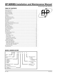
Table of Contents<br />
MODEL NOMENCLATURE...............................................3<br />
<strong>FHP</strong> MANUFACTURING....................................................3<br />
ADVANTAGES OF <strong>FHP</strong>’s TECHNOLOGY.......................3<br />
EC SERIES MODEL 007 – 070.........................................3<br />
FEATURES........................................................................3<br />
Cabinet .......................................................................3<br />
Quiet Operation ..........................................................4<br />
Serviceability ..............................................................4<br />
Unit Configurations......................................................4<br />
Filter Racks.................................................................4<br />
Hanging Brackets........................................................4<br />
Blower & Motor............................................................5<br />
Water Connections......................................................6<br />
Refrigerant Circuit.......................................................6<br />
Unit Protection Module................................................7<br />
UPM Features.............................................................7<br />
UNIT OPTIONS .................................................................8<br />
Hot Gas Reheat..........................................................8<br />
Refrigerant Flow Path.................................................8<br />
Hot Gas Reheat Sequence of Operation -<br />
On/Off Control.............................................................9<br />
Hot Gas Reheat Control Options................................9<br />
Special Considerations...............................................9<br />
Low Temperature Well Water......................................9<br />
Indoor Pool Dehumidifying During Winter Months .....9<br />
Sequence of Operation - Modulating Hot Gas Reheat<br />
(MHGRH)..................................................................10<br />
Hot Gas Bypass........................................................10<br />
Psychometric Chart...................................................10<br />
Fluid Differential Pressure Switch.............................11<br />
DDC Controls:...........................................................11<br />
SYSTEMS........................................................................12<br />
Water Source Cooling Tower/Boiler Systems............12<br />
Geothermal Systems.................................................12<br />
Earth Coupling Options.............................................12<br />
Vertical Ground Loop System...................................13<br />
Horizontal Ground Loop System...............................13<br />
Surface Water, Lake or Pond System.......................13<br />
TYPICAL HEAT PUMP OPERATING MODES................14<br />
Cooling Mode............................................................14<br />
Heating Mode............................................................14<br />
TYPICAL UNIT INSTALLATION......................................15<br />
Unit Location.............................................................15<br />
Vertical Unit Installation.............................................15<br />
Horizontal Unit Installation .......................................15<br />
Ductwork and Sound Attenuation Considerations.....16<br />
Piping........................................................................17<br />
Condensate Drain Piping..........................................17<br />
UNIT CONTROLS............................................................17<br />
Thermostats..............................................................17<br />
HOSE KITS......................................................................17<br />
Operating Limits – Cooling & Heating.......................18<br />
CERTIFIED PERFORMANCE DATA...............................19<br />
EC007 (300 CFM).....................................................21<br />
EC009 (350 CFM).....................................................22<br />
EC012 (400 CFM).....................................................23<br />
EC015 (500 CFM).....................................................24<br />
EC018 (650 CFM).....................................................25<br />
EC024 (850 CFM).....................................................26<br />
EC030 (950 CFM).....................................................27<br />
EC036 (1200 CFM)...................................................28<br />
EC041 (1150 CFM)...................................................29<br />
EC042 (1500 CFM)...................................................30<br />
EC048 (1600 CFM)...................................................31<br />
EC060 (2000 CFM)...................................................32<br />
EC070 (2200 CFM)...................................................33<br />
ELECTRICAL DATA........................................................34<br />
BLOWER PERFORMANCE CFM....................................35<br />
PHYSICAL DATA.............................................................36<br />
VERTICAL UNIT DIMENSIONS......................................37<br />
Vertical Top Discharge Water Source Heat Pump.....37<br />
Vertical Counterflow Water Source Heat Pump........38<br />
HORIZONTAL UNIT DIMENSIONS.................................39<br />
Horizontal Water Source Heat Pump........................39<br />
TYPICAL WIRING DIAGRAMS.......................................40<br />
1/2 through 6 ton | Single stage unit | 208-230V/1ph<br />
with PSC direct drive motor .....................................40<br />
1 through 6 tons | Single stage unit | 208-230V/1ph<br />
with PSC direct drive motor – Hot Gas Reheat.........41<br />
1/2 through 6 tons | Single stage unit | 208/230V/1ph<br />
with PSC direct drive motor – Economizer................42<br />
3 through 6 tons | Single stage unit | 208/230V/1ph<br />
with PSC direct drive motor – Hot Gas Reheat &<br />
Economizer...............................................................43<br />
2 through 6 tons | Single stage unit | 208/230V/3ph<br />
with PSC direct drive motor.......................................44<br />
2 through 6 tons | Single stage unit | 208-230V/3ph<br />
with PSC direct drive motor – Hot Gas Reheat.........45<br />
2 through 6 tons | Single stage unit | 208/230V/3ph<br />
with PSC direct drive motor – Economizer................46<br />
2 through 6 tons | Single stage unit | 208/230V/3ph<br />
with PSC direct drive motor – Hot Gas Reheat &<br />
Economizer...............................................................47<br />
SPECIFICATION GUIDE.............................................48-51<br />
6720220353<br />
Subject to change without prior notice Revised 10-12
Model Nomenclature<br />
MODEL NOMENCLATURE<br />
EC Series 3<br />
EC 036- 1 VT C -F L T<br />
SERIES:<br />
EC<br />
NOMINAL CAPACITY:<br />
SUPPLY AIR LOCATION:<br />
T - TOP<br />
VOLTAGE DESIGNATION:<br />
F - FRONT<br />
0 - 115/1/60 R - REAR<br />
1 - 208/1/60 & 230/1/60 S - STRAIGHT THRU<br />
2 - 277/1/60 E - END BL0W<br />
3 - 208/3/60 & 230/3/60 B - BOTTOM<br />
4 - 460/3/60<br />
5 - 575/3/60 RETURN AIR LOCATION:<br />
L - LEFT<br />
CABINET CONFIGURATION:<br />
R - RIGHT<br />
VT - VERTICAL<br />
B - BACK<br />
HZ - HORIZONTAL<br />
F - FRONT<br />
CF - COUNTERFLOW<br />
WATER CONNECTIONS<br />
HEAT EXCHANGER MATERIAL:<br />
LOCATION:<br />
C - COPPER F - FRONT<br />
N - CUPRO-NICKEL<br />
<strong>FHP</strong> MANUFACTURING<br />
Specializing in efficient green technology for<br />
commercial heating and cooling products, <strong>FHP</strong> is<br />
one of the leading manufacturers of Geothermal<br />
and Water Source heat pumps, which assures that<br />
you are buying a unit you can trust. We are part of<br />
Bosch Thermotechnology Ltd., a Robert Bosch<br />
Group unit dedicated to providing highly efficient<br />
heating and cooling solutions to the private and<br />
public sector.<br />
<strong>FHP</strong> headquarters has a state of the art facility with<br />
the latest manufacturing technology available. Each<br />
unit is factory tested according to Bosch quality<br />
standards in order to ensure our customers the<br />
highest level of satisfaction and comfort. We<br />
carefully select our suppliers in order to equip our<br />
products with the best components available.<br />
ADVANTAGES OF <strong>FHP</strong>’s TECHNOLOGY<br />
• Low installation costs<br />
• Lower operating costs<br />
• Flexibility and comfort<br />
• Energy efficiency<br />
• Space savings<br />
• Superior quality<br />
• Quiet operation<br />
EC SERIES MODEL 007 – 070<br />
• 13 Models from ½ through 6 tons<br />
• Horizontal, Vertical and Counterflow Configurations<br />
FEATURES<br />
Cabinet<br />
<strong>FHP</strong> EC unit cabinetry is constructed using<br />
Galvalume + sheet metal with a clear acrylic<br />
coating. This steel provides superior corrosion<br />
protection for units located indoors.<br />
All interior surfaces are lined with ½" thick, 1.5 lb./cu.ft.<br />
density, Micromat insulation for thermal insulation and<br />
acoustical attenuation. This insulation is noncombustible,<br />
non-hydroscopic and does not support<br />
fungal growth. Insulation meets NFPA 90A and 90B for<br />
fire protection and is certified to meet the GREENGUARD<br />
Indoor Air Quality Standard for Low Emitting Products.<br />
Protection against corrosion is a feature in the EC series.<br />
A stainless steel drain pan will last the lifetime of the unit<br />
and resist corrosion and cracking that may occur with<br />
steel or plastic materials.<br />
Revised 10-12<br />
Subject to change without prior notice<br />
6720220353
4<br />
EC Series<br />
Quiet Operation<br />
Air side coils have aluminum side plates to prevent<br />
corrosion.<br />
Taking all into consideration the life expectancy of<br />
the EC series is anticipated to be well in excess of<br />
the industry standard of 19 years.<br />
Quiet Operation<br />
All panels are insulated with ½" thick, 1.5 lb./cu.ft.<br />
density fiberglass insulation for both thermal<br />
insulation and noise reduction.<br />
Noise reduction is a critical consideration of the unit<br />
design. Even under normal operating conditions,<br />
vibration may be transmitted to the building<br />
structure and introduced into the space as noise. All<br />
EC units have a unique floating base pan where the<br />
compressor is mounted on a heavy steel plate that<br />
rests on a high density rubber pad in the base of the<br />
unit. In addition, compressors are mounted on<br />
rubber grommets. This double isolation, unique to<br />
<strong>FHP</strong>, is standard in all EC series units preventing<br />
vibration and noise transmission from the<br />
compressor to the unit structure resulting in<br />
exceptionally quiet operation.<br />
Insulated bulkheads in all units, separate the<br />
compressor section from the blower section,<br />
allowing the unit to be serviced during operation.<br />
Large removable panels aid in servicing the unit,<br />
when necessary. Separate electrical knockouts in<br />
the unit corner post allow for easy and safe<br />
routing of high and low voltage lines to the inside<br />
of the cabinet.<br />
Unit Configurations<br />
All units are available in horizontal and vertical and<br />
counterflow configurations. Additionally, several<br />
options of return air and supply air are offered as<br />
standard, providing configuration flexibility.<br />
Filter Racks<br />
Units come standard with a 1" filter rack and<br />
construction filter. A 2" four-sided filter rack and<br />
pleated filter is optional and greatly reduces<br />
unfiltered air from entering the unit. Filter doors<br />
allow for easy routine maintenance and changing<br />
of the air filter. A 1" return duct collar is integral to<br />
the filter rack eliminating the need for field mounted<br />
duct collars. Units are shipped with a 1" filter;<br />
2" pleated filters are available as an option.<br />
For additional sound attenuation, a compressor<br />
blanket is available as an option on unit sizes 018<br />
and above.<br />
Serviceability<br />
Optional 2" Filter<br />
Hanging Brackets<br />
Optional 2" Filter Rack<br />
All horizontal units come standard with hanging<br />
bracket kits for suspending the unit from field<br />
supplied hanger rods. These kits include heavy duty<br />
steel brackets and rubber grommets for sound and<br />
vibration isolation from the building structure.<br />
All units are designed to be serviced from the front of<br />
the unit. Schrader valves for high and low pressure<br />
gauges and the electrical box components are easily<br />
accessible for diagnosing and servicing the unit.<br />
6720220353<br />
Subject to change without prior notice Revised 10-12
Unit Configurations<br />
EC Series 5<br />
Access<br />
Panel<br />
Condenser Water Out<br />
Access<br />
Panel<br />
Access<br />
Panel<br />
Condensate Drain<br />
Condenser Water In<br />
Electrical Knock-Outs<br />
Condenser Water Out<br />
Access<br />
Panel<br />
Condensate Drain<br />
Condenser Water In<br />
Left Hand Return Top Discharge FLT<br />
Electrical Knock-Outs<br />
Right Hand Return Top Discharge FRT<br />
Condenser<br />
Water Out<br />
Condenser<br />
Water In<br />
Electrical<br />
Knock-Outs<br />
Left Hand Return Bottom Discharge FLB<br />
Condensate Drain<br />
Right Hand Return Bottom Discharge FRB<br />
Front<br />
Return Air Left<br />
Return Air Right<br />
Front<br />
Straight Through FLS<br />
End Blow FLE<br />
End Blow FRE<br />
Straight Through FRS<br />
Typical Horizontal Unit Configurations<br />
Blower & Motor<br />
Large blower wheels allow the unit to operate at<br />
lower speeds for quieter operation.<br />
PSC blower motors are standard on all unit sizes .<br />
A 1" supply air duct-flange connection is standard,<br />
facilitating duct installation on the unit. Horizontal<br />
units are field convertible from straight through to<br />
an end discharge arrangement.<br />
1" Duct-Flange<br />
Revised 10-12<br />
Subject to change without prior notice<br />
6720220353
6<br />
EC Series<br />
Water Connections<br />
Water Connections<br />
All water connections are heavy duty bronze FPT<br />
fittings securely fastened to the unit corner post.<br />
This allows connecting to a flexible hose kit without<br />
the use of a backup wrench making for easier, faster<br />
installation.<br />
Refrigerant Circuit<br />
EC series units are designed using the optimum<br />
combination of compressor, water and air coils to<br />
provide peak performance.<br />
Heavy duty heat pump compressors are used in all<br />
units. Rotary, reciprocating and scroll compressors<br />
offer optimum performance for each unit size.<br />
In geothermal applications where fluid temperatures<br />
can drop below the dew point of the surrounding air,<br />
optional insulation is available to prevent water coils<br />
and refrigerant piping from sweating.<br />
Air coils are state of the art, employing lanced fin<br />
and rifled tubing for maximum heat transfer. Large<br />
face areas result in lower face velocity reducing<br />
sound while ensuring high latent heat removal for<br />
maximum dehumidification in the cooling mode.<br />
A pilot operated four-way reversing valve in the<br />
refrigeration circuit allows the unit to operate in<br />
either the heating or cooling mode. All <strong>FHP</strong> units<br />
have the reversing valve energized in cooling<br />
mode, which allows the unit to fail to heating<br />
mode for building protection. This will ensure you<br />
are not left without heat in the middle of winter.<br />
should the reversing valve coil fail.<br />
Refrigerant to water heat exchangers are coaxial<br />
tube-in-tube type providing a robust construction,<br />
ensuring years of trouble free operation. Coaxial<br />
coils are selected and designed for peak<br />
performance, offering the best combination of low<br />
water pressure drop and maximum heat transfer in<br />
both the cooling and heating modes. Standard<br />
coaxial coils have a copper interior water tube and<br />
a steel outer shell. Optional Cupro-Nickel coils are<br />
available for applications where the water is of<br />
lower quality.<br />
Refrigerant flow to the air coil is controlled by<br />
capillary tubes as standard in EC units through 5<br />
tons. Thermal Expansion Valves come standard on<br />
the optional Extended Range EC and are designed<br />
to vary the flow of refrigerant depending on the<br />
load. TXV’s provide unit optimization and a more<br />
stable control over a wider range of operating<br />
conditions.<br />
EC Series units are rated to withstand 600 PSIG<br />
working refrigerant pressure and 400 PSIG<br />
working water pressure.<br />
All EC units, two tons and above, are provided with<br />
filter driers to ensure that no residual water or<br />
other foreign material is present to contaminate<br />
the refrigerant system and lead to premature<br />
failure.<br />
6720220353<br />
Subject to change without prior notice Revised 10-12
Unit Protection Module<br />
High and low pressure switches are factory installed<br />
in the refrigerant circuit, protecting the unit against<br />
high pressure conditions or loss of refrigerant charge.<br />
Schrader service valves are standard on the high and<br />
low pressure lines of all units, allowing connection to<br />
gauges for service diagnostics and to either evacuate,<br />
reclaim or recharge refrigerant into the system.<br />
Unit Protection Module<br />
Each EC unit is factory provided with a Unit Protection<br />
Module (UPM) that controls the unit operation<br />
and monitors the safety controls that protect the<br />
unit. The UPM interfaces with the thermostat or<br />
direct digital controller. The main purpose of the<br />
UPM is to protect the compressors by monitoring<br />
the different states of switches and sensors. This<br />
module provides time delays and protects the unit<br />
against freezing of the water to refrigerant heat<br />
exchangers as well as condensate overflow when<br />
the appropriate sensors are installed.<br />
Safety controls include the following:<br />
• High pressure switch located in the refrigerant<br />
discharge line.<br />
• Low pressure switch located in the unit refrigerant<br />
suction line.<br />
• Optional low fluid temperature (freeze) protection<br />
sensor. The freeze protection sensor, located<br />
on the refrigerant liquid line entering the coaxial<br />
heat exchanger is designed to disable compressor<br />
operation when the unit is in the heating<br />
mode, should the refrigerant temperature fall<br />
below either 30°F or 15°F. (The default setting is<br />
30 degrees farenheit, however this can be<br />
changed to 15 degrees farenheit by cutting the<br />
R42 resistor located above the Dip Switch SW1).<br />
If the temperature drops below or remains at the<br />
freeze limit trip for 30 seconds, the controller will<br />
shut the compressor down and enter into a soft<br />
EC Series 7<br />
lockout condition. The status LED will display the<br />
fault code, but the alarm contact will be inactive.<br />
• Optional Condensate overflow protection sensor<br />
factory mounted in the drain pan of the unit. Standard<br />
on all horizontal units.<br />
UPM Features<br />
• ANTI-SHORT CYCLE TIMER—5 minute delay on<br />
break timer to prevent compressor short cycling.<br />
• RANDOM START—Each controller has a unique<br />
random start delay ranging from 270 to 300<br />
seconds after power is applied to the board. This<br />
will prevent the simultaneous start of multiple<br />
units after a power outage.<br />
• LOW PRESSURE BYPASS TIMER—The low<br />
pressure switch is bypassed for 120 seconds<br />
after it opens to prevent nuisance low pressure<br />
lockouts during cold start-up in the heating mode.<br />
• BROWNOUT/SURGE/POWER INTERRUPTION<br />
PROTECTION—Prevents compressor operation<br />
should the voltage drop below 10% of unit rated<br />
value. The unit will restart once the voltage is within<br />
tolerance and the random start has timed out.<br />
• MALFUNCTION (ALARM) OUTPUT—The controller<br />
has a set of contacts for remote fault indication.<br />
This can be either a steady output or can be<br />
set to pulse with the fault code. Two connections<br />
are available one to provide a 24 volt output, the<br />
other to provide a dry contact.<br />
• TEST SERVICE MODE—A dip switch setting is provided<br />
to reduce all time delay settings to 10<br />
seconds maximum during troubleshooting for<br />
verification of unit operation.<br />
• L.E.D. FAULT INDICATION—Two L.E.D. indicators<br />
are provided as follows:<br />
• GREEN: Power L.E.D. indicates 18 – 30 VAC<br />
present at the board.<br />
• RED: Fault indicator with blink codes<br />
identifying the particular fault.<br />
1 Blink - High Pressure<br />
2 Blinks - Low Pressure<br />
3 Blinks - Low Fluid Temperature (Freeze Protection)<br />
4 Blinks - Condensate Overflow<br />
5 Blinks - Brownout condition<br />
Revised 10-12<br />
Subject to change without prior notice<br />
6720220353
8<br />
EC Series<br />
Unit Options<br />
• INTELLIGENT RESET—If a fault condition is<br />
initiated, the 5 minute delay on break time period<br />
is initiated and the unit will restart after this delay<br />
expires. The UPM is configurable for either 2 or 4<br />
fault occurrences before going into a hard lockout.<br />
The selection is made through a dip switch<br />
setting on the board. If the fault condition still<br />
exists or reoccurs twice or four times within one<br />
hour, the unit will go into a hard lockout and<br />
requires a manual lockout reset. A condensate<br />
overflow fault will, however, put the unit into a<br />
hard lockout immediately.<br />
• LOCKOUT RESET—A hard lockout can be reset by<br />
turning the unit thermostat off and then back on<br />
or by shutting off unit power at the circuit breaker.<br />
The method of reset is selectable by the dip<br />
switch on the board.<br />
UNIT OPTIONS<br />
Hot Gas Reheat<br />
Hot gas reheat (HGR) allows the user to not only<br />
control space temperature, but also humidity levels<br />
within the conditioned space. Excessive moisture in<br />
the space can promote mold growth leading to<br />
damage in the structure or interior surfaces, as well<br />
as reducing the air quality and creating an unhealthy<br />
environment.<br />
Possible causes of excess humidity could be by the<br />
unit having to operate under a widely varying load,<br />
an oversized short cycling unit, a high percentage of<br />
unconditioned outside air being introduced into the<br />
space, a high latent load in the space or any location<br />
where humidity infiltration is a problem.<br />
Typical unit control is by a wall mounted thermostat<br />
that senses temperature in the occupied space. By<br />
utilizing a humidistat in addition to the thermostat,<br />
we are able to monitor the humidity levels in the<br />
space as well. The HGR option allows cooling and<br />
dehumidification to satisfy both the thermostat and<br />
humidistat while preventing over cooling of the<br />
space while in the dehumidification mode.<br />
Once the thermostat reaches set point temperature<br />
and the humidity is above set point, the unit controller<br />
will energize the reheat valve operating the<br />
unit in hot gas reheat mode, first cooling and<br />
dehumidify, then reheating the air using hot refrigerant<br />
gas before delivering it to the space, usually<br />
2° to 5°F below room temperature. The unit is<br />
operating as a dehumidifier. By reheating the air<br />
along a constant sensible heat line, the relative<br />
humidity of the leaving air is reduced. This option<br />
offers significant energy savings over the traditional<br />
means of reheating air with electric heating coils.<br />
The moisture removal capacity of a specific heat<br />
pump is determined by the unit latent capacity<br />
rating. A heat pump’s latent capacity can be determined<br />
by reviewing the heat pump specification<br />
data sheets. Depending upon the entering water<br />
and air conditions, a total and sensible capacity can<br />
be interpolated from the data sheets. Subtracting<br />
sensible capacity from total capacity yields latent<br />
capacity. Dividing the latent capacity by 1069 (BTU/<br />
LB of water vapor at 80° DB and 67° WB) yields the<br />
amount of moisture removal in pounds per hour.<br />
Refrigerant Flow Path<br />
Check Valve<br />
Sub-Assembly<br />
Figure 1<br />
Reheat Coil<br />
Air<br />
Flow<br />
Oil<br />
Return<br />
Bleed<br />
Line<br />
Evaporator<br />
Coil<br />
Bypass Regulator<br />
Hot Gas Line<br />
Distributor<br />
Air Flow<br />
Equalizer Line<br />
Expansion Valve<br />
Reversing<br />
Valve<br />
Hot Gas<br />
Reheat<br />
Equalizer Line<br />
Discharge Out<br />
Water<br />
Liquid<br />
Line<br />
Condenser<br />
Coil<br />
TXV<br />
Sensing<br />
Bulb<br />
Compressor Suction In<br />
A hot gas reheat valve and a reheat coil are included<br />
in the refrigerant circuit. The refrigerant circuit in<br />
the cooling and heating mode is identical to a<br />
standard heat pump.<br />
In the reheat mode, the compressor discharge gas<br />
is diverted through the reheat valve to the reheat<br />
coil which is located downstream of the cooling<br />
coil. The superheated refrigerant gas reheats the air<br />
leaving the cooling coil. The hot refrigerant gas then<br />
passes though the water to refrigerant coil where it<br />
6720220353<br />
Subject to change without prior notice Revised 10-12
Sequence of Operation<br />
EC Series 9<br />
is condensed to a liquid. From this point the rest of<br />
the cooling cycle is completed as in a regular heat<br />
pump. There are two check valves to prevent<br />
refrigerant flow into the reheat coil during standard<br />
cooling/heating cycles. A small copper bleeder line<br />
is connected to the outlet line of the reheat coil and<br />
between the expansion valve outlet and distributor<br />
to the air coil. This line is necessary to let any<br />
liquid/oil that may have migrated to the reheat coil<br />
during reheat to escape during standard cooling/<br />
heating modes. (See Figure 1)<br />
Hot Gas Reheat Sequence of Operation<br />
-On/Off Control<br />
The sequence of operation in the cooling and<br />
heating mode is the same as a regular heat pump.<br />
In the reheat mode, on a call from the humidistat,<br />
the reheat relay coil is energized through the “H”<br />
circuit. The cooling relay remains de-energized<br />
enabling the reheat solenoid. The blower relay,<br />
reversing valve and compressor contactor are<br />
energized through contacts on the reheat relay. See<br />
typical wiring diagram page 41. (Note: The reheat<br />
mode always operates in the cooling mode.) Should<br />
the temperature in the space increase above set<br />
point, the compressor terminal Y is energized,<br />
which will de-energize the reheat valve putting the<br />
unit into straight cooling mode. A call for cooling or<br />
heating will always take precedence over hot gas<br />
reheat.<br />
Hot Gas Reheat Control Options<br />
There are several ways to control heat pumps with<br />
hot gas reheat. You should choose the means that<br />
best suits your specific application. Please refer to<br />
the Hot Gas Reheat wiring diagrams for typical<br />
thermostat wiring. Most heat pump compatible<br />
thermostats in conjunction with a humidistat are<br />
acceptable for use, (Note: “O” output for reversing<br />
valve energized in cooling mode is required.)<br />
Combination thermostat/humidistat are also<br />
available.<br />
Special Considerations<br />
Some applications require special attention to<br />
maximize the performance of the hot gas reheat<br />
function:<br />
• Low Temperature Well Water<br />
• Indoor Pool Dehumidifying During Winter Months<br />
(Re: Heating Mode)<br />
Consult the factory for special application<br />
considerations.<br />
Low Temperature Well Water<br />
When low temperature well water is utilized as the<br />
water source (below 55°F), a means of establishing<br />
two flow rates, one for the cooling/reheat mode<br />
and one for heating mode is recommended. In the<br />
cooling mode at low entering water temperatures<br />
and standard flow rates, discharge pressures and<br />
corresponding discharge gas temperatures are<br />
relatively low. At these conditions, when the reheat<br />
mode is initiated, the low temperature discharge<br />
gas can reduce reheat capacity. A means to reduce<br />
the water flow rate and elevate the discharge<br />
pressure/ temperature in cooling/reheat mode<br />
should be provided. Conversely, at low entering<br />
water temperatures in the heating mode, system<br />
suction pressure is reduced causing a loss in<br />
heating capacity. A means of providing higher flow<br />
in the heating mode should be provided. The<br />
simplest way to accomplish the above is to install<br />
water regulating valves.<br />
Indoor Pool Dehumidifying During Winter<br />
Months<br />
It is important to remember that when in the<br />
reheat/dehumidification mode the heat pump is<br />
cooling and reheating. A secondary means of<br />
heating the space during the dehumidification<br />
mode should be provided. The indoor space temperature<br />
should be kept at least two (2) degrees F<br />
above the pool water temperature. If this is not<br />
done the warm pool water attempts to heat the<br />
space and the humidity levels increase exponentially.<br />
The heat pump is normally sized to handle the<br />
design latent load moisture removal. A second heat<br />
pump or resistance heat should be provided to<br />
handle the structures shell loss load.<br />
Protective coatings are highly recommended for<br />
all pool applications, due to the highly corrosive<br />
chemical environment.<br />
Revised 10-12<br />
Subject to change without prior notice<br />
6720220353
10<br />
EC Series<br />
Hot Gas Bypass<br />
Sequence of Operation - Modulating Hot<br />
Gas Reheat (MHGRH)<br />
Modulating Hot Gas Reheat differs from On/Off in<br />
that the reheat function is always active. The<br />
purpose of MHGRH is to deliver air at or close to<br />
neutral conditions.<br />
Air is cooled and dehumidified by the cooling coil to<br />
around 55°F DB/54°F WB. A sensor located in the<br />
supply air stream is set at the required leaving dry<br />
bulb temperature and will send a signal to the<br />
modulating hot gas reheat valve to direct the flow of<br />
hot gas to maintain that temperature. See psychometric<br />
chart diagram( Figure 2). A typical application<br />
for this would be in treating 100% outside air.<br />
This air would be ducted directly into the space<br />
relieving the unit handling the zone of any outside<br />
air load. This can result in a smaller zone unit, less<br />
air flow and a savings in both initial and operating<br />
cost.<br />
Control of the hot gas modulation is by the thermostat<br />
in the supply air duct or through a building<br />
management system. A separate controller is used<br />
to control the unit itself.<br />
Hot Gas Bypass<br />
The function of the hot gas bypass valve is to<br />
prevent icing of the air coil when the unit is operating<br />
at low load conditions. This situation could arise<br />
if the space experiences widely different loads, for<br />
example a conference center. Without a hot gas<br />
bypass circuit the evaporating temperature will fall<br />
and ice could form on the coil restricting air flow<br />
and aggravating the situation. Eventually the coil<br />
could be totally blocked resulting in possible<br />
refrigerant liquid entering the compressor and<br />
failure of the system.<br />
The hot gas bypass valve located in the compressor<br />
discharge line diverts hot gas to the inlet of the air<br />
coil. The valve is factory set to open when the<br />
evaporating pressure falls to 75 PSI and will modulate<br />
to prevent the pressure falling any lower. This<br />
setting is field adjustable and this set point may be<br />
adjusted as required.<br />
Psychometric Chart<br />
Figure 2<br />
85<br />
85<br />
85 WET BULB TEMPERATURE - °F<br />
80<br />
80<br />
75<br />
80<br />
75<br />
65<br />
70<br />
70<br />
75<br />
Entering<br />
70<br />
65<br />
DEW POINT TEMPERATURE - °F<br />
60<br />
90%<br />
65<br />
60<br />
50<br />
55<br />
Lvg. Coil<br />
80%<br />
70%<br />
55<br />
60%<br />
60<br />
Reheat<br />
25%<br />
55<br />
50<br />
40<br />
35<br />
45<br />
40<br />
45<br />
50<br />
50%<br />
40%<br />
30%<br />
20%<br />
10% RELATIVE HUMIDITY<br />
15%<br />
8% RELATIVE HUMIDITY<br />
6%<br />
4%<br />
2%<br />
45<br />
40<br />
35<br />
30<br />
25<br />
20<br />
10<br />
0<br />
35 40 45 50 55 60 65 70 75 80 85 90 95 100<br />
Chart by: HANDS DOWN SOFTWARE, www.handsdownsoftware.com<br />
DRY BULB TEMPERATURE - °F<br />
6720220353<br />
Subject to change without prior notice Revised 10-12
DDC Controls<br />
EC Series 11<br />
Fluid Differential Pressure Switch<br />
The function of the differential pressure switch is to<br />
prevent or stop compressor operation should the<br />
water supply fail. This will prevent the unit from<br />
locking out on a safety requiring a manual reset to<br />
restart.<br />
The switch is piped between the water entering and<br />
leaving connections. Should the pressure drop fall<br />
below set value, the switch will open de-energizing<br />
the DPS relay, thereby stopping the compressor.<br />
The blower operation will not be affected by this<br />
option.<br />
DDC Controls:<br />
The <strong>FHP</strong> factory mounted DDC Controller is preprogrammed<br />
and installed in the unit with the Unit<br />
Protection Module (UPM) to be job site ready. The<br />
unit will operate in a 100% stand-alone control<br />
mode or connect to a Building Automation System<br />
(BAS) using open protocols BACnet, Modbus, N2 or<br />
LonWorks. Stand-alone DDC modules must use<br />
remote intelligent sensors and are to be programmed<br />
by the <strong>FHP</strong> bacview controller only.<br />
Zone temperatures, leaving air temperatures and<br />
water temperatures can be monitored from the<br />
central control computer and unit fault indication<br />
displayed.<br />
Available inputs/outputs include:<br />
• Discharge air temperature<br />
• Leaving water temperature<br />
• Fan run time<br />
• Override time remaining<br />
• Night setback status<br />
• Percent of units cooling<br />
• Percent of units heating<br />
• Cooling set points<br />
• Heating set points<br />
• Status of all the alarms<br />
• Space temperature<br />
• Occupied heating and cooling set points<br />
• Continuous or cycle fan during occupied mode<br />
• Command for occupied or unoccupied mode<br />
• Command for override of the unoccupied mode<br />
(unit resorts to occupied set points)<br />
• Set point adjustment<br />
To complement the controller, <strong>FHP</strong> offers a line of<br />
intelligent space sensors, which provide precision<br />
measurement and communication capabilities in an<br />
attractive low profile enclosure. A hidden communications<br />
jack provides access to the HVAC control<br />
system for commissioning and maintenance.<br />
Models available include:<br />
• The RS Standard which has no local temperature<br />
set point adjustment.<br />
• The RS Plus offers a local set point adjustment<br />
and override to an occupied mode and LED<br />
indication of current status.<br />
• The RS Pro has a large LCD display and easy-touse<br />
occupant controls for set point adjustment.<br />
A backview hand held diagnostic tool is available to<br />
allow local access to display and modify user<br />
defined properties without any computer software.<br />
RS Standard RS Plus RS Pro<br />
Revised 10-12<br />
Subject to change without prior notice<br />
6720220353
12<br />
EC Series<br />
Systems<br />
SYSTEMS<br />
EC series may be used in a variety of different<br />
applications depending on the system design. An<br />
overview of Tower/Boiler and Geothermal systems<br />
is given below. There could be several variations<br />
and combinations of these systems.<br />
Water Source Cooling Tower/Boiler Systems<br />
Water source cooling tower/boiler systems have<br />
been used for many years and are recognized as<br />
having a low installation cost and providing more<br />
energy efficient operation that most other systems<br />
on the market.<br />
In a typical building each office or space would<br />
receive its own heat pump. This ensures that the<br />
unit will independently satisfy the heating or<br />
cooling requirements for that space irrespective of<br />
the requirements of any other space. Unlike some<br />
other systems, this offers individual control and<br />
enhanced comfort in that area.<br />
All the units are connected to a common water loop<br />
containing, in addition to the heat pumps, a cooling<br />
tower, boiler, a primary and standby pump and a<br />
loop water temperature controller. In the summer<br />
cooling mode, the units are cooling and rejecting<br />
heat to the water loop. This heat is then rejected to<br />
the atmosphere through a cooling tower. In winter,<br />
heat is taken from the loop and, together with the<br />
compressor’s heat of compression, used to heat<br />
the space. The heat removed from the loop is then<br />
replenished by the boiler. The loop water temperature<br />
controller will keep the fluid within certain<br />
temperature limits typically 70°F in winter and 85°F<br />
in summer by cycling either the cooling tower or<br />
boiler operation.<br />
In today’s modern buildings the interior core<br />
usually has a net cooling requirement year round<br />
irrespective of the outside temperature. This is due<br />
to the internal heat gains from people, office<br />
equipment and lighting. The heat from these units<br />
in cooling is rejected to the common water loop and<br />
is absorbed by those units on the buildings perimeter<br />
that are in the heating mode. In effect we are<br />
transferring energy around the building from where<br />
it is in excess to those areas where it is needed. In<br />
many instances we find a balanced system where<br />
the heat generated in the interior space is sufficient<br />
to heat the perimeter resulting in neither the<br />
cooling tower nor boiler operating. This concept,<br />
unique to a water source system, provides the most<br />
energy efficient system on the market.<br />
Geothermal Systems<br />
The earth has a tremendous capacity of storing<br />
thermal energy, which can be utilized to heat or<br />
cool a building.<br />
A Geothermal system offers all the benefits of a<br />
cooling tower and boiler system with the additional<br />
advantage of having overall greater energy efficiency.<br />
As the cost of energy increases geothermal<br />
installations are becoming the system of choice by<br />
developers and design engineers.<br />
There are several alternative methods of utilizing<br />
the energy contained in a geothermal system, giving<br />
the design engineer several options for selecting<br />
the one that is right for a particular application.<br />
Earth Coupling Options<br />
Ground Loop Systems (Closed Loop)<br />
Lengths of high density polyethylene piping are<br />
buried in the earth either in vertical bore holes or<br />
horizontal trenches depending on the space available.<br />
Fluid from the loop inside the building circulates<br />
through these pipes either rejecting heat to the<br />
ground when there is a net cooling requirement or<br />
absorbing heat from the ground when heating is the<br />
dominant requirement.<br />
The temperature of the earth below 6 feet is relatively<br />
constant and is not affected by the ambient<br />
temperature. For this reason, the ground temperature<br />
is cooler than the summer ambient and warm-<br />
6720220353<br />
Subject to change without prior notice Revised 10-12
Vertical Ground Loop System<br />
EC Series 13<br />
er than the winter ambient in most regions. Geothermal<br />
systems are able to operate effectively in<br />
extreme ambient conditions exceeding 100°F in<br />
summer and -30°F in winter. This is one of the<br />
reasons why geothermal systems have such an<br />
advantage over other systems. An additional advantage<br />
is that no fossil fuels are used reducing the<br />
carbon emission of the building.<br />
Even in areas which are cooling or heating dominate<br />
a hybrid system can be used with a downsized<br />
cooling tower or boiler. This system will reduce the<br />
installed cost significantly with only a modest<br />
impact on overall operating efficiency.<br />
Geothermal systems may cost more to install but<br />
the savings in energy and low maintenance costs<br />
more than off set this with payback times typically<br />
five years or even less.<br />
Vertical Ground Loop System<br />
Horizontal Ground Loop System<br />
This type is cost effective on smaller projects or<br />
where there is sufficient space for the loop field.<br />
Trenches, three to six feet deep are dug in which a<br />
series of high density polyethylene pipes are laid.<br />
These loops are manifolded and connected to the<br />
loop inside the building which feeds the heat<br />
pumps. The fluid is then circulated, absorbing or<br />
rejecting heat to the earth depending on the requirement<br />
for heating or cooling.<br />
Surface Water, Lake or Pond System<br />
This method is used mainly in commercial buildings<br />
or where space for a loop field is limited. Vertical<br />
holes 100 to 400 feet deep are drilled in the ground,<br />
and a single loop of high density polyethylene pipe<br />
with a U-tube at the bottom is installed. The bore<br />
hole is then sealed with grout to ensure good<br />
contact for heat transfer with the soil. The size of<br />
the project will determine how many bore holes are<br />
required. The vertical ground loops are then connected<br />
to a horizontal header pipe that carries fluid<br />
to the building and circulated to each heat pump.<br />
The Earth’s temperature is stable below the surface<br />
which is an advantage for this system and provides<br />
for the greater efficiency. Vertical ground loop fields<br />
may be located under buildings or parking lots. The<br />
life expectancy is in excess of 50 years.<br />
This type of design is economical when a project is<br />
located near a body of water. Fluid circulates<br />
through polyethylene piping in a closed system, just<br />
as it does through ground loops but in this case<br />
underwater. The pipes may be coiled in a slinky to<br />
fit more surfaces into a given amount of space. The<br />
lake needs to be a minimum size and depth depending<br />
on the building load. Lake loops have no adverse<br />
impact on the aquatic system. Specialized<br />
lake heat exchangers are also available for this<br />
application. New technology is emerging for stainless<br />
steel and titanium heat exchangers.<br />
Revised 10-12<br />
Subject to change without prior notice<br />
6720220353
14<br />
EC Series<br />
Well Water System<br />
Well Water System<br />
This type of installation is only possible if there is<br />
sufficient ground water available in a well. The<br />
water must be of good quality. Local codes may<br />
limit the use of this system in certain areas. The<br />
arrangement is referred to as an open system<br />
which means that water is pumped directly from<br />
the source into the geothermal unit and then<br />
discharged either into a return well or a body of<br />
water. The water quality is unaffected other than a<br />
change in the temperature.<br />
TYPICAL HEAT PUMP OPERATING<br />
MODES<br />
Cooling Mode<br />
In the cooling mode, the refrigerant, a hot gas, is<br />
pumped from the compressor to the water to<br />
refrigerant heat exchanger via the reversing valve.<br />
Water, generally with an anti freeze, flowing<br />
through the water-to-refrigerant heat exchanger<br />
transfers heat from the refrigerant to the fluid<br />
raising its temperature while condensing the hot<br />
gas into a liquid. This liquid refrigerant then flows<br />
through a metering device to the air-to-refrigerant<br />
heat exchanger coil.<br />
In evaporating into a gas, the liquid absorbs heat<br />
and cools and dehumidifies the air that passes over<br />
the coil surface. The cooling cycle is completed<br />
when the refrigerant flows as a low pressure gas<br />
through the reversing valve and back to the suction<br />
side of the compressor.<br />
Cool dehumidified air is circulated to the space<br />
maintaining comfort conditions.<br />
Heating Mode<br />
During the heating mode, the refrigerant, a hot gas,<br />
is pumped from the compressor to the air-to-refrigerant<br />
heat exchanger coil via the reversing valve.<br />
In the air-to-refrigerant heat exchanger coil, the<br />
heat is removed by the air that passes over the coil<br />
surface, and the hot gas condenses into a liquid.<br />
The heated air is ducted to the space and provides<br />
heating for the building.<br />
The refrigerant liquid then flows through a metering<br />
system to the water-to-refrigerant heat exchanger.<br />
Basic Refrigeration Cycle<br />
Water to Air Heat Pump Cycle—<br />
Cooling Mode<br />
Loop Fluid<br />
Loop Fluid<br />
Loop<br />
Loop<br />
Fluid<br />
Fluid<br />
Loop Fluid<br />
Loop Fluid<br />
Loop<br />
Loop<br />
Fluid<br />
Fluid<br />
Loop Fluid<br />
Cool Refrigerant Gas<br />
Cool Refrigerant Gas<br />
Air to<br />
Air to<br />
Refrigerant<br />
Refrigerant<br />
Heat<br />
Heat<br />
Cool<br />
Exchanger<br />
Refrigerant Cool<br />
Exchanger<br />
Refrigerant Gas<br />
Thermal<br />
Gas<br />
Expansion Thermal<br />
Expansion Valve<br />
Valve<br />
Warm Liquid Refrigerant<br />
Warm Liquid Refrigerant<br />
Water Water to to<br />
Refrigerant<br />
Heat<br />
Exchanger<br />
Hot Refrigerant Gas Gas<br />
Cold Liquid Refrigerant<br />
Water to<br />
Refrigerant<br />
Heat<br />
Exchanger<br />
Cold Liquid Refrigerant<br />
Cold Liquid Refrigerant<br />
Water to Air Heat Pump Cycle—<br />
Heating Mode<br />
Cool<br />
Cool<br />
Refrigerant<br />
Refrigerant<br />
Gas<br />
Gas<br />
ReversingValve<br />
ReversingValve<br />
Hot<br />
Hot<br />
Refrigerant<br />
Refrigerant<br />
Gas Gas<br />
Compressor<br />
Compressor<br />
Hot Hot Refrigerant Gas Gas<br />
Hot Refrigerant Gas<br />
Air to<br />
Refrigerant<br />
Heat<br />
Hot<br />
Exchanger<br />
Refrigerant<br />
Gas<br />
Thermal<br />
Expansion<br />
Valve<br />
Cool Refrigerant Gas<br />
Warm Liquid Refrigerant<br />
Cool<br />
Refrigerant Gas<br />
ReversingValve<br />
Hot<br />
Refrigerant<br />
Gas<br />
Hot Refrigerant Gas<br />
Compressor<br />
6720220353<br />
Subject to change without prior notice Revised 10-12
Typical Unit Installation<br />
Water, generally with an anti freeze, circulates<br />
through this heat exchanger and is cooled by the<br />
evaporating refrigerant which evaporates into a gas.<br />
The heating cycle is completed when the refrigerant<br />
flows as a low pressure gas through the reversing<br />
valve and back to the suction side of the compressor.<br />
TYPICAL UNIT INSTALLATION<br />
Unit Location<br />
Any mechanical device will, at some point in time<br />
require servicing and repair.<br />
With this in mind sufficient space must be provided<br />
around the unit for service personnel to perform<br />
maintenance or repair.<br />
Units are not designed for outdoor installation. Avoid<br />
locations where the unit may be exposed to freezing<br />
conditions or where the humidity levels could cause<br />
condensation on the unit panels for example when<br />
exposed to outdoor ambient conditions.<br />
Vertical Unit Installation<br />
EC Series 15<br />
Sufficient space must be provided for filter replacement<br />
and access to the compressor and blower for<br />
service.<br />
Units should be set on a piece of rubber, neoprene<br />
or other vibration absorbing material at least 1/3"<br />
to ½" thick. The pad should extend 3/4" over the<br />
entire base of the unit.<br />
Avoid direct line of sight to the unit. Install a sound<br />
baffle over any door that has a return air grille.<br />
See figure 3 for typical installation.<br />
Horizontal Unit Installation<br />
Figure 3<br />
Vertical units are normally installed in a closet or<br />
mechanical plant room.<br />
If installed in a closet or other confined space,<br />
ensure adequate space for return air to the unit.<br />
Horizontal units are typically suspended above the<br />
ceiling by four (field supplied) 3/8" threaded rods<br />
fastened to the unit by the factory supplied hanger<br />
bracket kits. The kits include rubber isolators to<br />
help prevent transmission of vibration and noise to<br />
the building structure. Units should be located<br />
directly below a structural member so that it is<br />
securely anchored.<br />
A horizontal unit should be positioned to allow for<br />
removal of the filters and access panels. Allow at<br />
least 18" clearance on each side of the unit for<br />
service and 36" in front of the unit for maintenance<br />
access. The filter needs to be slid out and sufficient<br />
space must be provided to allow this.<br />
Do not install the unit above any piping or electrical<br />
raceways. The unit should be able to be removed to<br />
the floor without major rearrangement of other<br />
mechanical or ceiling components.<br />
Consideration needs to be made as to the location<br />
of the units. Avoid installing units directly above<br />
occupied spaces (e.g. above office desks or classrooms).<br />
This will minimize possible disruption to<br />
the occupants if maintenance or service is required<br />
Revised 10-12<br />
Subject to change without prior notice<br />
6720220353
16<br />
EC Series<br />
Typical Unit Installation<br />
as well as keeping a potential source of noise out of<br />
the area. If possible, units should be installed above<br />
the hallway drop ceiling in schools, and the supply<br />
and return air is routed directly into classrooms.<br />
Local code may require fire dampers to be used in<br />
this application.<br />
Ductwork and Sound Attenuation<br />
Considerations<br />
Take-offs should be at<br />
least five feet away<br />
from the plenum<br />
Lining the first<br />
five feet of supply duct<br />
reduces noise<br />
Supply Air Ducting<br />
Turns attenuate<br />
blower hose<br />
Sound is becoming an increasingly important factor in<br />
Lining the first<br />
all HVAC installations. five feet of supply The duct EC series has been designed<br />
Turns attenuate<br />
to minimize reduces sound, noise but sound acoustical blower hose design plays<br />
an important part of the sound level in the space.<br />
Most of the problems associated Flex with HVAC<br />
duct<br />
generated sound can be avoided by paying Flex close<br />
Take-offs should be at<br />
duct<br />
attention to duct design and equipment placement.<br />
least five feet away<br />
from the plenum<br />
A discharge flange is provided on all horizontal unit<br />
models for fastening of ductwork. We recommend<br />
Return air<br />
using a flexible filter and collar grillebetween the discharge flange<br />
and the duct transformation to reduce vibration<br />
transmission from the cabinet and to simplify<br />
disconnection of the unit from the ceiling ductwork.<br />
Return air<br />
filter and grille<br />
Flex<br />
duct<br />
Return Air Ducting<br />
Flex<br />
duct<br />
Return air to the unit could be either free return or<br />
ducted. The filter rack is provided with a 1" flange<br />
should a ducted return be used. We recommend<br />
using a flexible collar between the return flange<br />
and the duct transformation to reduce vibration<br />
transmission from the cabinet and to simplify<br />
disconnection of the unit from the ductwork.<br />
Sound is transmitted down ductwork and it is<br />
important to avoid direct line of sight between the<br />
unit and the space, both on the return or supply<br />
side. To accomplish this, design the duct runs with<br />
two 90° turns.<br />
As a general recommendation, duct interiors<br />
should have an acoustic / thermal lining of least 1 / 2 "<br />
thick over the entire duct run or a minimum of the<br />
first 5 feet of the supply trunk.<br />
Line the last five diameters of duct before each<br />
outlet with one-inch thick sound blanket. Line<br />
elbows and transition pieces, as well as a short<br />
distance upstream and downstream of the fittings.<br />
Elbows, tees and dampers can create turbulence or<br />
distortion in the airflow. Using aerodynamic fittings<br />
will help in reducing this effect. Place a straight<br />
length of duct, 5 to 10 times the duct width, before<br />
the next fitting to smooth out airflow.<br />
Diffusers that are located in the bottom of a trunk<br />
duct can also produce noise.<br />
Balancing dampers should be located several duct<br />
widths upstream from an air outlet.<br />
Ductwork should be mounted and supported using<br />
isolation devices that absorb vibration.<br />
Applications such as Hotel, Motel, Dormitory or<br />
Nursing Home that use a single duct discharge are<br />
susceptible to noise. These applications typically<br />
have low static pressures and short duct lengths. In<br />
these applications the discharge duct must be fully<br />
lined and have a square elbow without turning<br />
vanes. A velocity not exceeding 500 to 600 fpm is<br />
recommended. Return air for these applications<br />
should enter through a sidewall grille and route up<br />
the stud space to a ceiling plenum.<br />
For horizontal heat pumps mounted in the ceiling<br />
plenum, an insulated return plenum is sometimes<br />
placed at the return air opening to further attenuate<br />
line-of-sight sound transmission through return<br />
openings.<br />
6720220353<br />
Subject to change without prior notice Revised 10-12
Unit Controls<br />
EC Series 17<br />
Piping<br />
The water loop system is typically designed using a<br />
“reverse return” piping system which includes a<br />
flow control device so that flow requirements are<br />
met for each zone.<br />
A high pressure stainless steel flexible hose kit is<br />
recommended to connect the unit to the building’s<br />
hard piping and acts as a sound attenuator for both<br />
the unit operating noise and hydraulic pumping<br />
noise. One end of the hose has a swivel fitting to<br />
facilitate removal of the unit for replacement or<br />
service.<br />
Hose kits come in several configurations, but in all<br />
cases should include supply and return shutoff ball<br />
valves to allow removal of a unit without the need to<br />
shut down the entire heat pump system. The hose<br />
kit may contain either a manual or automatic flow<br />
control that may be preset to ensure correct water<br />
flow to the unit.<br />
Other components of the hose kit may be a Y-strainer<br />
to prevent dirt from fouling the water coil. A blow<br />
down valve is recommended with the Y-strainer.<br />
Many installations today use variable frequency<br />
drives on the water loop pump as an energy saving<br />
measure. This requires the flow to the unit be shut<br />
off when it is not operating. This can be accomplished<br />
by including a 2-way solenoid valve in the<br />
hose kit, which is field wired to open when the<br />
compressor is energized.<br />
Pressure / Temperature ports should be included in<br />
these fittings to allow the service technician to<br />
measure water flow and temperatures when checking<br />
unit operation.<br />
Condensate Drain Piping<br />
Condensate piping can be made of steel, copper or<br />
PVC pipe. In most cases, PVC pipe eliminates the<br />
need to wrap insulation around the pipe to prevent<br />
sweating.<br />
A ¾" FPT condensate drain connection is installed<br />
in the unit. The condensate piping must be trapped<br />
at the unit and pitched away from the unit not less<br />
than 1/4" per foot. A vent is required after the trap<br />
so that the condensate will drain away from the<br />
unit. The vent can also act as a cleanout if the trap<br />
becomes clogged. The condensate drain should not<br />
be directly piped to a drain/waste/vent stack. See<br />
local codes for the correct application of condensate<br />
piping to drains.<br />
UNIT CONTROLS<br />
Thermostats<br />
The unit control may be as simple as a single stage<br />
thermostat or the unit may have a DDC controller<br />
integrated into the building management system.<br />
Multiple Stage Thermostats<br />
All external low voltage control wiring is made to<br />
the thermostat terminal located in the unit electrical<br />
box.<br />
Thermostats may be manual changeover, auto<br />
change over, programmable or non programmable<br />
depending on the requirements of the project. A<br />
full line of thermostats are available from <strong>FHP</strong> as<br />
an accessory.<br />
HOSE KITS<br />
Hose kits are recommended between the unit and<br />
system loop piping. This will help eliminate the<br />
transmission of vibration and noise from the unit<br />
to the space.<br />
Hoses are fire rated fiber reinforced EPDM Stainless<br />
Steel braid hoses with swivel connections.<br />
Maximum working pressure 400 PSI for sizes ½" –<br />
1" and 300 PSI for sizes 1 ¼" – 2".<br />
A variety of hose kits are available depending on<br />
the job requirement.<br />
Kit 1 Hose only either 24" or 36" long.<br />
Revised 10-12<br />
Subject to change without prior notice<br />
6720220353
18<br />
EC Series<br />
Performance Data<br />
Kit 2 Hose kit 1 with ball valves on the supply and<br />
return hoses. Valves have P/T (pressure/temperature)<br />
ports to facilitate pressure and temperature<br />
readings.<br />
Kit 3 Hose kit 2 with an automatic flow control<br />
valve. The design flow rate is preset at the factory<br />
per the design conditions and will automatically<br />
limit the flow to this value. This will greatly<br />
facilitate balancing of the fluid loop and ensuring<br />
each unit gets the required flow.<br />
Kit 4 Hose kit 3 with a Y-strainer and blow down<br />
valve on the supply side. The filter screen is 20<br />
mesh, 304 stainless steel to help prevent dirt and<br />
debris from entering the water coil.<br />
Kit 5 Hose kit 3 with a 24 v 2 position solenoid<br />
valve. This could be used to shut off flow to the unit<br />
when there is not call for heating or cooling. A<br />
typical application would be with VFD pumping.<br />
Kit 6 Hose kit 4 with a 24 v 2 position solenoid<br />
valve. Hose kit options are available in the accessories<br />
section of the BST selection software.<br />
Operating Limits<br />
<strong>FHP</strong> EC series are capable of operating over a wide<br />
range of conditions. For operation in a geothermal<br />
application or any other installation where the loop<br />
fluid temperature may drop below the ambient dew<br />
point, the extended range option is recommended.<br />
This consists of additional insulation on the piping<br />
to prevent condensation.<br />
• Maximum and minimum fluid conditions are at<br />
unit rated flow rate.<br />
• Maximum and minimum operating limits may not<br />
be combined. If one value is at either maximum<br />
or minimum the other two should be at normal<br />
operating range.<br />
• Entering fluid temperatures below 45°F in the<br />
heating mode require antifreeze.<br />
Operating Limits – Cooling & Heating<br />
Standard Unit<br />
Extended Range<br />
Option<br />
COOLING<br />
Minimum ambient air temperature °F 50 50<br />
Maximum ambient air temperature °F 100 100<br />
Minimum evaporator entering air db/wb °F 68/57 68/57<br />
Rated air coil entering air db/wb °F 80/67 80/67<br />
Maximum evaporator entering air db/wb °F 95/85 95/85<br />
Minimum water coil entering fluid temperature °F 50 50<br />
Water loop typical coil entering fluid range temperature °F 70/90 70/90<br />
Maximum water coil entering fluid temperature °F 110 110<br />
HEATING<br />
Minimum ambient air temperature °F 50 40<br />
Maximum ambient air temperature °F 100 85<br />
Minimum evaporator entering air db °F 50 50<br />
Rated air coil entering air °F 68 68<br />
Maximum evaporator entering air db °F 80 80<br />
Normal water coil entering fluid range °F 50-80 25-80<br />
Minimum water coil entering Fluid °F 50 20*<br />
* = antifreeze solution is required at these fluid temperatures.<br />
6720220353<br />
Subject to change without prior notice Revised 10-12
Certified Performance Data<br />
EC Series 19<br />
CERTIFIED PERFORMANCE DATA<br />
ARI/ISO 13256-1 PERFORMANCE DATA<br />
ENTERING WATER TEMPERATURES<br />
MODEL<br />
Fluid<br />
Flow<br />
Rate<br />
86˚F 68˚F 59°F 50°F 77˚F 32˚F<br />
WATER LOOP GROUND WATER GROUND LOOP<br />
CAPACITY AND EFFICIENCY DATA<br />
Cooling<br />
Capacity<br />
(WLHP)<br />
EER<br />
(WLHP)<br />
Heating<br />
Capacity<br />
(WLHP)<br />
COP<br />
(WLHP)<br />
Cooling<br />
Capacity<br />
(GWHP)<br />
EER<br />
(GWHP)<br />
Heating<br />
Capacity<br />
(GWHP)<br />
COP<br />
(GWHP)<br />
Cooling<br />
Capacity<br />
(GLHP)<br />
EER<br />
(GLHP)<br />
Heating<br />
Capacity<br />
(GLHP)<br />
COP<br />
(GLHP)<br />
EC007 2.0 6,200 12.50 8,000 5.10 7,200 20.0 6,000 4.0 6,500 15.00 4,500 3.20<br />
EC009 2.5 7,800 13.70 11,400 4.70 9,000 20.0 8,600 3.8 8,100 14.80 6,400 3.20<br />
EC012 3.0 11,000 13.00 14,500 4.50 12,400 19.0 11,500 3.6 11,500 14.50 8,700 3.10<br />
EC015 4.0 14,000 13.00 18,000 4.60 15,800 19.0 13,500 3.8 14,500 15.00 10,100 3.30<br />
EC018 5.0 18,500 13.00 24,000 4.40 21,400 19.0 18,000 3.8 19,800 14.10 13,400 3.30<br />
EC024 6.0 25,000 13.80 30,000 4.50 28,200 20.6 23,800 3.8 26,500 15.20 17,900 3.30<br />
EC030 7.0 29,000 13.00 35,000 4.30 33,000 18.6 28,400 3.8 31,000 14.40 21,000 3.30<br />
EC036 9.0 36,000 13.80 46,000 4.50 40,200 19.5 36,200 4.0 37,800 15.50 27,400 3.30<br />
EC041 9.0 38,000 12.50 49,000 4.20 40,400 16.1 39,000 3.7 39,200 14.10 28,500 3.1<br />
EC042 10.0 42,000 13.00 53,000 4.20 44,500 18.5 42,000 3.8 43,800 14.20 32,200 3.30<br />
EC048 12.0 48,000 14.00 58,000 4.80 58,000 20.6 46,600 4.2 52,000 15.40 36,800 3.50<br />
EC060 15.0 62,000 13.20 79,000 4.40 67,000 18.3 61,500 3.9 63,600 14.70 50,000 3.30<br />
EC070 16.0 68,000 13.50 80,000 4.50 76,000 19.8 68,000 4.0 70,000 15.20 53,000 3.30<br />
Tabulated performance data is at noted water temperatures and entering air conditions of 80.6°F DB/66.2°F WB at<br />
ARI/ISO 13256-1 rated CFM.<br />
Revised 10-12<br />
Subject to change without prior notice<br />
6720220353
20<br />
EC Series<br />
Unit Selection<br />
UNIT SELECTION<br />
To ensure that you get the optimal performance<br />
from your <strong>FHP</strong> heat pump it is important that they<br />
be selected accurately to match your design<br />
conditions.<br />
Prior to making equipment selections the zone<br />
conditions need to be determined. <strong>FHP</strong> <strong>Manufacturing</strong><br />
recommends using a building load program to<br />
determine the heating and cooling loads.<br />
The catalog provides a wide range of entering air<br />
and water conditions that will meet most applications.<br />
The unit performance can be determined by<br />
referring to the data tables from page 21 to 35.<br />
Our Bosch Select Tools Selection Software (BST) is<br />
designed to provide you with a fast and accurate<br />
selection based on your specific conditions. This<br />
software is available through the commercial<br />
website. You may click on the BST link and request<br />
an account.<br />
The following is a typical example for a unit selection.<br />
Design conditions are given as follows:<br />
Total Cooling Load<br />
Sensible Cooling Load<br />
Total Heating Load<br />
Air Flow Required<br />
= 35.57 MBTUH<br />
= 29.00 MBTUH<br />
= 38.92 MBTUH<br />
= 1400 CFM<br />
Entering Air Temp Cooling (db/wb) = 75°F / 63°F<br />
Entering Air Temp Heating = 60°F<br />
Entering Water Temp Cooling = 80°F<br />
Entering Water Temp Heating = 70°F<br />
<strong>FHP</strong> model EC036 would not be sufficient given<br />
these conditions as it provides a total cooling<br />
capacity of 36.9 MBTUH and a sensible capacity of<br />
28.1 MBTUH.<br />
The next size unit, the EC041 has a total cooling<br />
capacity of 40.7 MBTUH and a sensible capacity of<br />
29.3 MBTUH. This meets the design conditions as<br />
closely as possible.<br />
Please be aware that interpolation between ratings<br />
within a table is allowed, but extrapolation is a<br />
method of estimating new data by expanding<br />
outside a known range of data points and should<br />
not be considered accurate.<br />
6720220353<br />
Subject to change without prior notice Revised 10-12
Capacity Data<br />
EC Series 21<br />
EC007 (300 CFM)<br />
Entering<br />
Fluid Temp<br />
(F)<br />
50<br />
60<br />
70<br />
80<br />
85<br />
90<br />
100<br />
110<br />
Water<br />
Flow<br />
(GPM)<br />
Pressure<br />
Drop<br />
(FOH)<br />
1 1.8<br />
2 6.3<br />
3 13.1<br />
1 1.7<br />
2 6.1<br />
3 12.6<br />
1 1.7<br />
2 5.9<br />
3 12.2<br />
1 1.6<br />
2 5.7<br />
3 11.8<br />
1 1.6<br />
2 5.6<br />
3 11.6<br />
1 1.6<br />
2 5.5<br />
3 11.4<br />
1 1.5<br />
2 5.4<br />
3 11.1<br />
1 1.5<br />
2 5.2<br />
3 10.8<br />
COOLING<br />
Total<br />
Entering Air<br />
Capacity<br />
Temp (db/wb) F<br />
(MBTUH)<br />
Sensible<br />
Capacity<br />
(MBTUH)<br />
Heat of<br />
Rejection<br />
(MBTUH)<br />
Power<br />
Input (kW)<br />
EER<br />
Entering<br />
Fluid Temp<br />
(F)<br />
Entering<br />
Air Temp<br />
(F)<br />
HEATING<br />
Total<br />
Capacity<br />
(MBTUH)<br />
Heat of<br />
Absorption<br />
(MBTUH)<br />
75/63 7.7 6.2 9.0 0.40 19.2<br />
60 5.2 3.5 0.50 3.0<br />
80/67 8.2 6.5 9.5 0.40 20.7 70 5.1 3.3 0.53 2.8<br />
85/71 8.7 6.7 10.1 0.39 22.2 80 5.0 3.0 0.56 2.6<br />
75/63 7.9 6.4 9.2 0.38 21.0 60 5.5 3.8 0.51 3.2<br />
80/67 8.5 6.6 9.8 0.37 23.3 30 70 5.4 3.5 0.54 2.9<br />
85/71 9.1 6.8 10.5 0.36 25.5 80 5.2 3.2 0.57 2.7<br />
75/63 8.0 6.4 9.3 0.36 22.1 60 5.6 3.9 0.51 3.2<br />
80/67 8.6 6.6 9.9 0.36 24.3 70 5.4 3.6 0.54 2.9<br />
85/71 9.2 6.8 10.5 0.35 26.6 80 5.3 3.3 0.57 2.7<br />
75/63 7.3 6.1 8.6 0.45 16.4<br />
60 5.6 4.3 0.52 3.2<br />
80/67 7.8 6.3 9.1 0.44 17.7 70 5.6 4.0 0.55 3.0<br />
85/71 8.3 6.5 9.7 0.44 19.0 80 5.6 3.7 0.59 2.8<br />
75/63 7.5 6.2 8.8 0.42 17.9 60 6.5 4.7 0.51 3.7<br />
80/67 8.0 6.4 9.4 0.42 19.3 40 70 5.5 4.3 0.56 2.9<br />
85/71 8.6 6.6 10.0 0.41 21.1 80 5.5 4.0 0.60 2.7<br />
75/63 7.6 6.2 8.9 0.41 18.7 60 6.6 4.9 0.52 3.7<br />
80/67 8.1 6.5 9.5 0.40 20.2 70 6.1 4.5 0.56 3.2<br />
85/71 8.7 6.7 10.1 0.40 22.1 80 5.5 4.1 0.60 2.7<br />
75/63 6.8 5.9 8.2 0.49 13.9<br />
60 6.9 5.2 0.52 3.9<br />
80/67 7.3 6.1 8.7 0.49 15.0 70 6.8 4.9 0.56 3.6<br />
85/71 7.8 6.3 9.3 0.49 16.1 80 6.6 4.5 0.60 3.2<br />
75/63 7.1 6.0 8.4 0.47 15.3 60 7.5 5.7 0.52 4.2<br />
80/67 7.6 6.2 9.0 0.46 16.5 50 70 7.2 5.3 0.56 3.7<br />
85/71 8.1 6.5 9.5 0.46 17.7 80 7.0 4.9 0.61 3.4<br />
75/63 7.2 6.0 8.5 0.45 15.9 60 7.6 5.9 0.52 4.3<br />
80/67 7.7 6.3 9.1 0.45 17.2 70 7.4 5.5 0.56 3.8<br />
85/71 8.2 6.5 9.6 0.45 18.5 80 7.1 5.0 0.61 3.4<br />
75/63 6.4 5.7 7.8 0.54 11.9<br />
60 7.9 6.2 0.52 4.4<br />
80/67 6.9 6.0 8.3 0.54 12.9 70 7.7 5.8 0.56 4.0<br />
85/71 7.4 6.2 8.9 0.54 13.9 80 7.5 5.4 0.61 3.6<br />
75/63 6.7 5.8 8.0 0.51 13.1 60 8.5 6.8 0.52 4.7<br />
80/67 7.1 6.1 8.5 0.51 14.0 60 70 8.2 6.3 0.57 4.2<br />
85/71 7.6 6.3 9.1 0.51 15.0 80 7.9 5.9 0.61 3.8<br />
75/63 6.8 5.8 8.1 0.50 13.6 60 8.7 7.0 0.52 4.8<br />
80/67 7.2 6.1 8.6 0.50 14.5 70 8.4 6.5 0.57 4.3<br />
85/71 7.8 6.3 9.2 0.50 15.8 80 8.1 6.1 0.62 3.8<br />
75/63 6.2 5.6 7.6 0.56 11.1<br />
60 8.8 7.2 0.52 4.9<br />
80/67 6.7 5.9 8.1 0.56 12.0 70 8.6 6.7 0.57 4.4<br />
85/71 7.1 6.1 8.6 0.56 12.7 80 8.4 6.3 0.62 4.0<br />
75/63 6.4 5.7 7.8 0.54 12.0 60 9.5 7.9 0.53 5.3<br />
80/67 6.9 6.0 8.3 0.54 13.0 70 70 9.3 7.4 0.58 4.7<br />
85/71 7.4 6.2 8.9 0.53 13.9 80 9.0 6.9 0.62 4.2<br />
75/63 6.5 5.7 7.9 0.53 12.4 60 9.8 8.2 0.53 5.4<br />
80/67 7.0 6.0 8.4 0.52 13.4 70 9.5 7.6 0.58 4.8<br />
85/71 7.5 6.3 9.0 0.52 14.5 80 9.2 7.1 0.63 4.3<br />
75/63 6.0 5.5 7.4 0.59 10.3<br />
60 9.8 8.2 0.53 5.4<br />
80/67 6.4 5.8 7.9 0.59 11.0 70 9.6 7.7 0.58 4.9<br />
85/71 6.9 6.0 8.4 0.59 11.8 80 9.3 7.2 0.63 4.3<br />
75/63 6.2 5.6 7.6 0.56 11.1 60 10.6 9.1 0.53 5.9<br />
80/67 6.7 5.9 8.1 0.56 12.0 80 70 10.3 8.5 0.58 5.2<br />
85/71 7.1 6.1 8.6 0.56 12.7 80 10.0 7.9 0.63 4.6<br />
75/63 6.3 5.7 7.7 0.55 11.5 60 10.9 9.3 0.53 6.0<br />
80/67 6.8 5.9 8.2 0.55 12.5 70 10.6 8.8 0.58 5.3<br />
85/71 7.3 6.2 8.8 0.55 13.4 80 10.2 8.2 0.64 4.7<br />
75/63 5.6 5.3 7.0 0.63 8.9<br />
80/67 6.0 5.6 7.5 0.64 9.5<br />
Extended Range - Anti-freeze required<br />
85/71 6.4 5.8 8.0 0.64 10.1<br />
AHRI/ISO13256-1 certified performance is rated at entering air<br />
75/63 5.8 5.4 7.2 0.61 9.6 conditions of 80.6°F DB and 66.2°F WB in cooling and 68°F DB in<br />
80/67 6.2 5.7 7.7 0.61 10.2 heating.<br />
85/71 6.6 5.9 8.2 0.61 10.8<br />
75/63 5.9 5.5 7.3 0.60 9.9<br />
80/67 6.3 5.7 7.8 0.60 10.6<br />
85/71 6.8 6.0 8.3 0.60 11.4<br />
75/63 5.1 5.1 6.6 0.68 7.5<br />
80/67 5.5 5.3 7.0 0.69 8.0<br />
85/71 5.9 5.7 7.5 0.69 8.6<br />
75/63 5.4 5.2 6.8 0.66 8.3<br />
80/67 5.7 5.5 7.3 0.66 8.7<br />
85/71 6.2 5.8 7.7 0.66 9.4<br />
75/63 5.4 5.3 6.9 0.65 8.4<br />
80/67 5.8 5.6 7.3 0.65 9.0<br />
85/71 6.3 5.8 7.8 0.65 9.7<br />
Power<br />
Input<br />
(kW)<br />
Tabulated unit performance does not include fan or pump power<br />
corrections required for AHRI/ISO standard performance ratings.<br />
COP<br />
Unit performance may be interpolated. Extrapolation is not allowed.<br />
For conditions other than rating conditions provided, consult the <strong>FHP</strong><br />
BST selection software.<br />
Ratings below 40°F are with a methanol solution.<br />
Due to variations in installation, actual performance may vary from<br />
the tabulated data. Performance contained herein are as a result of<br />
extensive testing by <strong>FHP</strong> and are not express warranties between the<br />
parties and may be changed at any time.<br />
Continuous research and development to improve our products may<br />
result in a change to the current design and specifications without notice.<br />
Revised 10-12<br />
Subject to change without prior notice<br />
6720220353
22<br />
EC Series<br />
Capacity Data<br />
EC009 (350 CFM)<br />
Entering<br />
Fluid<br />
Temp (F)<br />
50<br />
60<br />
70<br />
80<br />
85<br />
90<br />
100<br />
110<br />
Water<br />
Flow<br />
(GPM)<br />
Pressure<br />
Drop<br />
(FOH)<br />
1 1.5<br />
2 5.2<br />
3 10.9<br />
1 1.5<br />
2 5.1<br />
3 10.5<br />
1 1.4<br />
2 4.9<br />
3 10.2<br />
1 1.4<br />
2 4.7<br />
3 9.8<br />
1 1.3<br />
2 4.7<br />
3 9.7<br />
1 1.3<br />
2 4.6<br />
3 9.5<br />
1 1.3<br />
2 4.5<br />
3 9.2<br />
1 1.2<br />
2 4.3<br />
3 9<br />
Entering Air<br />
Temp<br />
(db/wb) F<br />
COOLING<br />
Total<br />
Capacity<br />
(MBTUH)<br />
Sensible<br />
Capacity<br />
(MBTUH)<br />
Heat of<br />
Rejection<br />
(MBTUH)<br />
Power<br />
Input<br />
(kW)<br />
EER<br />
Entering<br />
Fluid Temp<br />
(F)<br />
Entering<br />
Air<br />
Temp<br />
(F)<br />
HEATING<br />
Total<br />
Capacity<br />
(MBTUH)<br />
Heat of<br />
Absorption<br />
(MBTUH)<br />
75/63 9.8 7.5 11.3 0.52 19.0<br />
60 6.2 4.2 0.58 3.1<br />
80/67 10.4 7.8 12.0 0.52 20.3 70 6.6 1.8 0.60 3.2<br />
85/71 11.1 8.0 12.8 0.51 21.7 80 6.5 1.7 0.64 3.0<br />
75/63 10.2 7.7 11.7 0.46 22.1 60 6.7 4.6 0.58 3.3<br />
80/67 10.9 8.0 12.4 0.46 24.0 30 70 6.7 2.9 0.62 3.2<br />
85/71 11.6 8.2 13.2 0.45 26.1 80 5.8 4.8 0.67 2.5<br />
75/63 10.3 7.7 11.8 0.45 23.1 60 6.8 4.8 0.59 3.4<br />
80/67 11.0 8.0 12.5 0.44 25.3 70 6.4 3.6 0.63 3.0<br />
85/71 11.8 8.3 13.3 0.43 27.8 80 6.8 4.1 0.68 2.9<br />
75/63 9.3 7.3 11.0 0.58 16.2<br />
60 7.1 5.1 0.59 3.5<br />
80/67 10.0 7.6 11.7 0.58 17.4 70 7.3 3.4 0.63 3.4<br />
85/71 10.6 7.8 12.4 0.58 18.5 80 7.3 2.4 0.66 3.2<br />
75/63 9.7 7.5 11.3 0.53 18.5 60 7.8 5.7 0.60 3.8<br />
80/67 10.4 7.7 12.0 0.52 20.1 40 70 7.7 5.3 0.65 3.5<br />
85/71 11.1 8.0 12.8 0.51 21.7 80 7.9 3.2 0.69 3.4<br />
75/63 9.8 7.5 11.4 0.51 19.2 60 8.0 6.0 0.60 3.9<br />
80/67 10.5 7.8 12.1 0.50 20.9 70 7.8 5.7 0.65 3.5<br />
85/71 11.3 8.1 12.9 0.49 22.9 80 7.9 3.5 0.69 3.3<br />
75/63 8.9 7.1 10.6 0.64 14.1<br />
60 8.2 6.2 0.61 4.0<br />
80/67 9.5 7.3 11.3 0.64 14.9 70 8.1 5.8 0.66 3.6<br />
85/71 10.1 7.6 12.0 0.64 15.8 80 7.9 5.4 0.71 3.3<br />
75/63 9.2 7.2 10.9 0.59 15.6 60 8.9 6.8 0.61 4.2<br />
80/67 9.9 7.5 11.6 0.59 16.9 50 70 8.9 6.3 0.67 3.9<br />
85/71 10.6 7.7 12.3 0.58 18.3 80 8.8 4.3 0.71 3.6<br />
75/63 9.3 7.3 11.0 0.58 16.2 60 9.3 7.2 0.62 4.4<br />
80/67 10.0 7.6 11.7 0.57 17.6 70 9.0 6.7 0.67 3.9<br />
85/71 10.7 7.8 12.4 0.56 19.0 80 8.1 7.8 0.73 3.3<br />
75/63 8.4 6.9 10.2 0.70 12.1<br />
60 9.3 7.3 0.62 4.4<br />
80/67 9.0 7.1 10.9 0.70 12.9 70 9.1 6.8 0.67 4.0<br />
85/71 9.6 7.4 11.5 0.71 13.7 80 9.0 6.5 0.73 3.6<br />
75/63 8.7 7.0 10.5 0.66 13.3 60 10.2 8.1 0.63 4.8<br />
80/67 9.3 7.3 11.2 0.66 14.3 60 70 9.7 7.4 0.68 4.2<br />
85/71 10.0 7.6 11.9 0.65 15.4 80 9.8 7.0 0.74 3.9<br />
75/63 8.8 7.1 10.5 0.64 13.7 60 10.6 8.4 0.63 4.9<br />
80/67 9.4 7.3 11.3 0.64 14.7 70 10.3 8.0 0.69 4.4<br />
85/71 10.1 7.6 12.0 0.64 15.9 80 9.9 7.2 0.74 3.9<br />
75/63 8.1 6.8 10.0 0.73 11.2<br />
60 10.4 8.4 0.63 4.8<br />
80/67 8.7 7.0 10.7 0.73 11.9 70 10.3 7.9 0.69 4.4<br />
85/71 9.3 7.3 11.3 0.74 12.7 80 10.1 7.5 0.75 3.9<br />
75/63 8.4 6.9 10.3 0.69 12.2 60 11.4 9.4 0.63 5.3<br />
80/67 9.1 7.2 10.9 0.69 13.3 70 70 11.2 8.9 0.70 4.7<br />
85/71 9.7 7.5 11.6 0.69 14.2 80 8.6 14.2 0.77 3.3<br />
75/63 8.5 7.0 10.3 0.68 12.6 60 11.9 9.9 0.64 5.5<br />
80/67 9.2 7.2 11.0 0.68 13.7 70 11.6 9.3 0.70 4.8<br />
85/71 9.8 7.4 11.8 0.67 14.6 80 11.2 8.8 0.77 4.3<br />
75/63 7.9 6.6 9.8 0.76 10.4<br />
60 11.5 9.5 0.64 5.3<br />
80/67 8.4 6.9 10.4 0.77 11.0 70 11.3 9.0 0.70 4.7<br />
85/71 9.0 7.2 11.1 0.77 11.7 80 11.1 8.5 0.76 4.2<br />
75/63 8.2 6.8 10.1 0.72 11.4 60 12.8 10.7 0.64 5.8<br />
80/67 8.8 7.1 10.7 0.72 12.2 80 70 12.5 10.2 0.71 5.1<br />
85/71 9.4 7.3 11.4 0.72 13.0 80 12.4 9.7 0.78 4.7<br />
75/63 8.3 6.9 10.1 0.71 11.7 60 13.3 11.3 0.64 6.0<br />
80/67 8.9 7.1 10.8 0.71 12.5 70 12.9 10.6 0.71 5.3<br />
85/71 9.5 7.4 11.5 0.71 13.4 80 12.7 9.8 0.78 4.7<br />
75/63 7.4 6.4 9.4 0.83 9.0<br />
80/67 7.9 6.7 10.0 0.83 9.5<br />
85/71 8.4 7.0 10.6 0.84 10.0<br />
Extended Range - Anti-freeze required<br />
75/63 7.7 6.5 9.6 0.79 9.7<br />
80/67 8.2 6.8 10.3 0.80 10.4<br />
85/71 8.8 7.1 10.9 0.80 11.1<br />
75/63 7.7 6.6 9.7 0.78 9.9<br />
80/67 8.3 6.9 10.3 0.79 10.6<br />
85/71 8.9 7.2 11.0 0.78 11.4<br />
75/63 6.9 6.2 9.0 0.89 7.8<br />
80/67 7.4 6.5 9.6 0.90 8.2<br />
85/71 7.9 6.7 10.2 0.91 8.7<br />
75/63 7.1 6.3 9.2 0.87 8.2<br />
80/67 7.6 6.6 9.8 0.87 8.8<br />
85/71 8.2 6.8 10.4 0.88 9.4<br />
75/63 7.1 6.3 9.2 0.86 8.3<br />
80/67 7.7 6.6 9.9 0.86 9.0<br />
85/71 8.3 6.9 10.5 0.86 9.7<br />
Power<br />
Input<br />
(kW)<br />
COP<br />
AHRI/ISO13256-1 certified performance is rated at entering air<br />
conditions of 80.6°F DB and 66.2°F WB in cooling and 68°F DB in<br />
heating.<br />
Tabulated unit performance does not include fan or pump power<br />
corrections required for AHRI/ISO standard performance ratings.<br />
Unit performance may be interpolated. Extrapolation is not allowed.<br />
For conditions other than rating conditions provided, consult the <strong>FHP</strong><br />
BST selection software.<br />
Ratings below 40°F are with a methanol solution.<br />
Due to variations in installation, actual performance may vary from<br />
the tabulated data. Performance contained herein are as a result of<br />
extensive testing by <strong>FHP</strong> and are not express warranties between the<br />
parties and may be changed at any time.<br />
Continuous research and development to improve our products may<br />
result in a change to the current design and specifications without notice.<br />
6720220353<br />
Subject to change without prior notice Revised 10-12
Capacity Data<br />
EC Series 23<br />
EC012 (400 CFM)<br />
Entering<br />
Fluid<br />
Temp (F)<br />
50<br />
60<br />
70<br />
80<br />
85<br />
90<br />
100<br />
110<br />
Water<br />
Flow<br />
(GPM)<br />
Pressure<br />
Drop<br />
(FOH)<br />
1.5 3.4<br />
2.5 8.5<br />
3.5 15.5<br />
1.5 3.3<br />
2.5 8.2<br />
3.5 15<br />
1.5 3.2<br />
2.5 7.9<br />
3.5 14.5<br />
1.5 3.1<br />
2.5 7.7<br />
3.5 14.1<br />
1.5 3<br />
2.5 7.5<br />
3.5 13.8<br />
1.5 3<br />
2.5 7.4<br />
3.5 13.6<br />
1.5 2.9<br />
2.5 7.2<br />
3.5 13.2<br />
1.5 2.8<br />
2.5 7<br />
3.5 12.8<br />
Entering Air<br />
Temp<br />
(db/wb) F<br />
COOLING<br />
Total<br />
Capacity<br />
(MBTUH)<br />
Sensible<br />
Capacity<br />
(MBTUH)<br />
Heat of<br />
Rejection<br />
(MBTUH)<br />
Power<br />
Input<br />
(kW)<br />
EER<br />
Entering<br />
Fluid Temp<br />
(F)<br />
Entering<br />
Air<br />
Temp<br />
(F)<br />
HEATING<br />
Total<br />
Capacity<br />
(MBTUH)<br />
Heat of<br />
Absorption<br />
(MBTUH)<br />
75/63 11.9 9.2 14.1 0.68 17.5<br />
60 8.2 5.4 0.85 2.8<br />
80/67 12.8 9.4 15.0 0.68 18.8 70 8.1 5.1 0.91 2.6<br />
85/71 13.5 9.7 15.7 0.68 19.9 80 8.0 4.7 0.96 2.4<br />
75/63 12.3 9.5 14.4 0.63 19.5 60 8.6 5.7 0.86 2.9<br />
80/67 13.1 9.6 15.2 0.63 20.9 30 70 8.4 5.3 0.92 2.7<br />
85/71 14.0 9.9 16.1 0.62 22.6 80 8.2 4.9 0.98 2.5<br />
75/63 12.5 9.5 14.5 0.61 20.5 60 8.8 5.9 0.87 3.0<br />
80/67 13.3 9.7 15.3 0.60 22.1 70 8.6 5.5 0.93 2.7<br />
85/71 14.3 10.0 16.3 0.59 24.1 80 8.4 5.1 0.98 2.5<br />
75/63 11.3 8.9 13.5 0.76 15.0<br />
60 9.4 6.5 0.89 3.1<br />
80/67 12.1 9.1 14.4 0.76 15.9 70 9.2 6.1 0.95 2.8<br />
85/71 12.9 9.4 15.2 0.76 16.9 80 9.1 5.7 1.02 2.6<br />
75/63 11.6 9.0 13.8 0.71 16.3 60 9.9 6.9 0.90 3.2<br />
80/67 12.5 9.3 14.7 0.71 17.7 40 70 9.7 6.4 0.97 2.9<br />
85/71 13.4 9.7 15.7 0.70 19.0 80 9.4 6.0 1.03 2.7<br />
75/63 11.8 9.1 13.9 0.69 17.1 60 10.1 7.1 0.91 3.3<br />
80/67 12.7 9.4 14.8 0.69 18.5 70 9.9 6.6 0.98 3.0<br />
85/71 13.6 9.8 15.8 0.68 20.0 80 9.7 6.1 1.04 2.7<br />
75/63 10.7 8.6 13.1 0.83 12.8<br />
60 10.7 7.7 0.93 3.4<br />
80/67 11.5 9.0 14.0 0.84 13.7 70 10.5 7.2 1.00 3.1<br />
85/71 12.2 9.3 14.8 0.85 14.4 80 10.2 6.7 1.07 2.8<br />
75/63 11.0 8.7 13.4 0.79 13.9 60 11.2 8.2 0.95 3.5<br />
80/67 11.8 9.2 14.2 0.79 14.9 50 70 11.0 7.6 1.02 3.2<br />
85/71 12.6 9.5 15.1 0.79 15.9 80 10.8 7.1 1.09 2.9<br />
75/63 11.2 8.8 13.5 0.77 14.5 60 11.5 8.5 0.95 3.5<br />
80/67 12.0 9.2 14.4 0.77 15.6 70 11.2 7.8 1.03 3.2<br />
85/71 12.8 9.4 15.2 0.77 16.7 80 11.0 7.3 1.10 2.9<br />
75/63 10.1 8.4 12.7 0.91 11.0<br />
60 12.1 9.0 0.96 3.7<br />
80/67 10.8 8.8 13.5 0.92 11.7 70 11.8 8.4 1.04 3.3<br />
85/71 11.6 9.1 14.3 0.93 12.4 80 11.6 7.8 1.12 3.0<br />
75/63 10.4 8.5 12.9 0.87 11.9 60 12.8 9.8 0.96 3.9<br />
80/67 11.2 8.9 13.7 0.88 12.8 60 70 12.5 9.1 1.05 3.5<br />
85/71 12.0 9.2 14.6 0.88 13.6 80 12.1 8.5 1.13 3.1<br />
75/63 10.5 8.5 13.0 0.86 12.3 60 13.2 10.1 0.97 4.0<br />
80/67 11.4 8.9 13.9 0.86 13.3 70 12.8 9.4 1.05 3.6<br />
85/71 12.2 9.3 14.7 0.86 14.2 80 12.5 8.7 1.14 3.2<br />
75/63 9.8 8.3 12.5 0.96 10.2<br />
60 13.6 10.5 0.97 4.1<br />
80/67 10.5 8.6 13.2 0.97 10.9 70 13.2 9.9 1.06 3.6<br />
85/71 11.2 8.9 14.0 0.98 11.5 80 13.1 9.2 1.15 3.4<br />
75/63 10.1 8.4 12.7 0.92 11.0 60 14.5 11.4 0.98 4.3<br />
80/67 10.9 8.7 13.5 0.92 11.8 70 70 14.1 10.7 1.07 3.9<br />
85/71 11.6 9.1 14.3 0.93 12.5 80 13.7 10.0 1.16 3.5<br />
75/63 10.3 8.5 12.8 0.90 11.4 60 14.9 11.8 0.99 4.4<br />
80/67 11.0 8.8 13.6 0.90 12.2 70 14.6 11.0 1.08 4.0<br />
85/71 11.8 9.2 14.4 0.91 13.0 80 14.0 10.3 1.17 3.5<br />
75/63 9.5 8.2 12.2 1.00 9.5<br />
60 15.1 12.1 1.00 4.4<br />
80/67 10.2 8.5 13.0 1.01 10.1 70 14.8 11.4 1.08 4.0<br />
85/71 10.9 8.8 13.8 1.02 10.7 80 14.5 10.7 1.18 3.6<br />
75/63 9.8 8.3 12.5 0.96 10.2 60 16.1 13.0 1.02 4.7<br />
80/67 10.5 8.6 13.2 0.97 10.9 80 70 15.9 12.2 1.10 4.2<br />
85/71 11.2 8.9 14.0 0.97 11.5 80 15.6 11.4 1.19 3.9<br />
75/63 9.9 8.3 12.5 0.94 10.5 60 16.6 13.4 1.02 4.8<br />
80/67 10.6 8.7 13.3 0.95 11.2 70 16.2 12.6 1.11 4.3<br />
85/71 11.4 9.0 14.2 0.95 12.0 80 15.9 11.9 1.20 3.9<br />
75/63 8.9 7.9 11.7 1.08 8.2<br />
80/67 9.5 8.2 12.5 1.10 8.7<br />
Extended Range - Anti-freeze required<br />
85/71 10.1 8.5 13.2 1.11 9.1<br />
75/63 9.1 7.8 11.9 1.05 8.7<br />
80/67 9.8 8.3 12.7 1.06 9.3<br />
85/71 10.5 8.6 13.5 1.07 9.8<br />
75/63 9.2 7.9 12.0 1.03 8.9<br />
80/67 9.9 8.4 12.8 1.04 9.5<br />
85/71 10.6 8.7 13.6 1.05 10.1<br />
75/63 8.1 7.7 11.2 1.17 6.9<br />
80/67 8.7 8.0 11.9 1.18 7.3<br />
85/71 9.4 8.2 12.7 1.20 7.8<br />
75/63 8.4 7.7 11.4 1.14 7.4<br />
80/67 9.1 8.0 12.2 1.15 7.9<br />
85/71 9.7 8.2 12.9 1.16 8.4<br />
75/63 8.4 7.8 11.4 1.12 7.5<br />
80/67 9.2 8.1 12.3 1.14 8.1<br />
85/71 9.8 8.2 13.0 1.14 8.6<br />
Power<br />
Input<br />
(kW)<br />
COP<br />
AHRI/ISO13256-1 certified performance is rated at entering air<br />
conditions of 80.6°F DB and 66.2°F WB in cooling and 68°F DB in<br />
heating.<br />
Tabulated unit performance does not include fan or pump power<br />
corrections required for AHRI/ISO standard performance ratings.<br />
Unit performance may be interpolated. Extrapolation is not allowed.<br />
For conditions other than rating conditions provided, consult the <strong>FHP</strong><br />
BST selection software.<br />
Ratings below 40°F are with a methanol solution.<br />
Due to variations in installation, actual performance may vary from<br />
the tabulated data. Performance contained herein are as a result of<br />
extensive testing by <strong>FHP</strong> and are not express warranties between the<br />
parties and may be changed at any time.<br />
Continuous research and development to improve our products may<br />
result in a change to the current design and specifications without notice.<br />
Revised 10-12<br />
Subject to change without prior notice<br />
6720220353
24<br />
EC Series<br />
Capacity Data<br />
EC015 (500 CFM)<br />
Entering<br />
Fluid<br />
Temp (F)<br />
50<br />
60<br />
70<br />
80<br />
85<br />
90<br />
100<br />
110<br />
Water<br />
Flow<br />
(GPM)<br />
Pressure<br />
Drop<br />
(FOH)<br />
2 4.2<br />
3 8.7<br />
4.5 18.1<br />
2 4.1<br />
3 8.4<br />
4.5 17.5<br />
2 3.9<br />
3 8.2<br />
4.5 16.9<br />
2 3.8<br />
3 7.9<br />
4.5 16.4<br />
2 3.8<br />
3 7.8<br />
4.5 16.1<br />
2 3.7<br />
3 7.7<br />
4.5 15.9<br />
2 3.6<br />
3 7.4<br />
4.5 15.4<br />
2 3.5<br />
3 7.2<br />
4.5 15<br />
Entering Air<br />
Temp<br />
(db/wb) F<br />
COOLING<br />
Total<br />
Capacity<br />
(MBTUH)<br />
Sensible<br />
Capacity<br />
(MBTUH)<br />
Heat of<br />
Rejection<br />
(MBTUH)<br />
Power<br />
Input<br />
(kW)<br />
EER<br />
Entering<br />
Fluid Temp<br />
(F)<br />
Entering<br />
Air<br />
Temp<br />
(F)<br />
HEATING<br />
Total<br />
Capacity<br />
(MBTUH)<br />
Heat of<br />
Absorption<br />
(MBTUH)<br />
75/63 15.8 12.2 18.2 0.74 21.3<br />
60 11.3 8.0 0.96 3.4<br />
80/67 16.8 12.6 19.3 0.73 22.9 70 11.1 7.4 1.04 3.1<br />
85/71 17.9 12.9 20.4 0.72 24.8 80 10.9 6.9 1.12 2.9<br />
75/63 16.2 12.4 18.5 0.69 23.5 60 11.7 8.4 0.97 3.5<br />
80/67 17.3 12.8 19.6 0.67 25.6 30 70 11.5 7.8 1.05 3.2<br />
85/71 18.4 13.1 20.8 0.66 28.0 80 11.3 7.2 1.13 2.9<br />
75/63 16.5 12.5 18.7 0.65 25.2 60 12.0 8.6 0.98 3.6<br />
80/67 17.6 12.9 19.9 0.63 27.7 70 11.7 8.0 1.06 3.3<br />
85/71 18.8 13.2 21.1 0.61 30.6 80 11.5 7.4 1.14 3.0<br />
75/63 15.0 11.9 17.6 0.84 17.8<br />
60 13.0 9.6 0.99 3.9<br />
80/67 16.0 12.2 18.7 0.84 19.1 70 12.7 9.0 1.08 3.5<br />
85/71 17.0 12.6 19.7 0.83 20.5 80 12.4 8.3 1.16 3.1<br />
75/63 15.4 12.0 17.9 0.79 19.4 60 13.5 10.1 1.00 4.0<br />
80/67 16.5 12.4 19.0 0.78 21.1 40 70 13.2 9.4 1.08 3.6<br />
85/71 17.5 12.8 20.1 0.77 22.8 80 12.9 8.7 1.17 3.2<br />
75/63 15.6 12.2 18.1 0.76 20.5 60 13.9 10.4 1.00 4.1<br />
80/67 16.8 12.5 19.2 0.74 22.6 70 13.5 9.7 1.09 3.6<br />
85/71 17.9 12.9 20.4 0.73 24.6 80 13.2 9.0 1.18 3.3<br />
75/63 14.2 11.5 17.0 0.95 15.0<br />
60 14.7 11.3 1.01 4.3<br />
80/67 15.1 11.9 18.0 0.94 16.0 70 14.4 10.6 1.10 3.8<br />
85/71 16.1 12.2 19.0 0.94 17.2 80 14.1 9.9 1.20 3.5<br />
75/63 14.6 11.7 17.3 0.90 16.2 60 15.4 11.9 1.02 4.4<br />
80/67 15.6 12.1 18.3 0.89 17.5 50 70 15.0 11.2 1.11 4.0<br />
85/71 16.6 12.4 19.4 0.88 18.9 80 14.7 10.4 1.21 3.6<br />
75/63 14.8 11.8 17.5 0.87 17.1 60 15.8 12.4 1.02 4.5<br />
80/67 15.8 12.2 18.5 0.85 18.5 70 15.4 11.6 1.12 4.0<br />
85/71 16.9 12.6 19.6 0.84 20.1 80 15.0 10.8 1.21 3.6<br />
75/63 13.4 11.2 16.4 1.05 12.7<br />
60 16.6 13.1 1.03 4.7<br />
80/67 14.3 11.6 17.3 1.05 13.6 70 16.2 12.3 1.13 4.2<br />
85/71 15.2 11.9 18.3 1.05 14.5 80 15.9 11.6 1.23 3.8<br />
75/63 13.7 11.3 16.6 1.00 13.6 60 17.3 13.9 1.04 4.9<br />
80/67 14.7 11.7 17.6 1.00 14.7 60 70 16.9 13.0 1.14 4.4<br />
85/71 15.6 12.1 18.6 0.99 15.7 80 16.4 12.2 1.24 3.9<br />
75/63 13.9 11.4 16.8 0.97 14.2 60 17.9 14.4 1.04 5.0<br />
80/67 14.9 11.8 17.8 0.97 15.4 70 17.4 13.5 1.14 4.5<br />
85/71 15.9 12.2 18.9 0.96 16.6 80 16.9 12.6 1.25 4.0<br />
75/63 12.9 11.0 16.0 1.10 11.7<br />
60 18.5 15.0 1.05 5.2<br />
80/67 13.8 11.4 17.0 1.10 12.5 70 18.0 14.1 1.15 4.6<br />
85/71 14.7 11.8 18.0 1.10 13.3 80 17.6 13.3 1.26 4.1<br />
75/63 13.3 11.1 16.3 1.06 12.5 60 19.4 15.9 1.05 5.4<br />
80/67 14.2 11.6 17.3 1.06 13.4 70 70 18.9 15.0 1.16 4.8<br />
85/71 15.2 11.9 18.3 1.05 14.4 80 18.4 14.0 1.27 4.3<br />
75/63 13.5 11.2 16.5 1.03 13.1 60 20.0 16.6 1.06 5.6<br />
80/67 14.5 11.6 17.5 1.02 14.1 70 19.4 15.5 1.16 4.9<br />
85/71 15.5 12.0 18.5 1.02 15.2 80 18.9 14.5 1.27 4.4<br />
75/63 12.5 10.9 15.7 1.16 10.8<br />
60 20.6 16.9 1.06 5.7<br />
80/67 13.4 11.2 16.7 1.16 11.5 70 19.9 16.0 1.17 5.0<br />
85/71 14.3 11.6 17.6 1.16 12.3 80 19.4 15.1 1.28 4.4<br />
75/63 12.9 11.0 16.0 1.11 11.6 60 21.6 18.0 1.06 6.0<br />
80/67 13.8 11.4 16.9 1.11 12.4 80 70 20.9 17.0 1.18 5.2<br />
85/71 14.7 11.8 17.9 1.11 13.2 80 20.3 15.9 1.29 4.6<br />
75/63 13.1 11.1 16.1 1.09 12.0 60 22.3 18.7 1.07 6.1<br />
80/67 14.0 11.5 17.1 1.08 12.9 70 21.5 17.7 1.18 5.3<br />
85/71 15.0 11.8 18.2 1.07 13.9 80 20.9 16.6 1.30 4.7<br />
75/63 11.7 10.2 15.1 1.26 9.2<br />
80/67 12.5 10.9 16.0 1.27 9.8<br />
85/71 13.4 11.3 16.9 1.27 10.5<br />
75/63 12.0 10.6 15.3 1.22 9.8<br />
Extended Range - Anti-freeze required<br />
80/67 12.9 11.0 16.3 1.23 10.5<br />
85/71 13.7 11.5 17.2 1.22 11.2<br />
75/63 12.2 10.7 15.5 1.20 10.2<br />
80/67 13.1 11.1 16.4 1.20 10.9<br />
85/71 14.0 11.5 17.4 1.19 11.7<br />
75/63 10.8 9.8 14.5 1.37 7.8<br />
80/67 11.6 10.3 15.3 1.38 8.4<br />
85/71 12.4 11.0 16.2 1.38 9.0<br />
75/63 11.1 9.9 14.6 1.34 8.3<br />
80/67 11.9 10.4 15.5 1.34 8.9<br />
85/71 12.8 11.1 16.5 1.34 9.5<br />
75/63 11.3 10.0 14.8 1.31 8.6<br />
80/67 12.1 10.5 15.7 1.31 9.2<br />
85/71 13.0 11.2 16.7 1.31 9.9<br />
Power<br />
Input<br />
(kW)<br />
COP<br />
AHRI/ISO13256-1 certified performance is rated at entering air<br />
conditions of 80.6°F DB and 66.2°F WB in cooling and 68°F DB in<br />
heating.<br />
Tabulated unit performance does not include fan or pump power<br />
corrections required for AHRI/ISO standard performance ratings.<br />
Unit performance may be interpolated. Extrapolation is not allowed.<br />
For conditions other than rating conditions provided, consult the <strong>FHP</strong><br />
BST selection software.<br />
Ratings below 40°F are with a methanol solution.<br />
Due to variations in installation, actual performance may vary from<br />
the tabulated data. Performance contained herein are as a result of<br />
extensive testing by <strong>FHP</strong> and are not express warranties between the<br />
parties and may be changed at any time.<br />
Continuous research and development to improve our products may<br />
result in a change to the current design and specifications without notice.<br />
6720220353<br />
Subject to change without prior notice Revised 10-12
Capacity Data<br />
EC Series 25<br />
EC018 (650 CFM)<br />
Entering<br />
Fluid<br />
Temp (F)<br />
50<br />
60<br />
70<br />
80<br />
85<br />
90<br />
100<br />
110<br />
Water<br />
Flow<br />
(GPM)<br />
Pressure<br />
Drop<br />
(FOH)<br />
2.5 6.3<br />
4 14.7<br />
5 21.9<br />
2.5 6.1<br />
4 14.2<br />
5 21.2<br />
2.5 5.9<br />
4 13.7<br />
5 20.5<br />
2.5 5.7<br />
4 13.3<br />
5 19.8<br />
2.5 5.6<br />
4 13.1<br />
5 19.5<br />
2.5 5.5<br />
4 12.9<br />
5 19.2<br />
2.5 5.4<br />
4 12.5<br />
5 18.7<br />
2.5 5.2<br />
4 12.1<br />
5 18.1<br />
Entering Air<br />
Temp<br />
(db/wb) F<br />
COOLING<br />
Total<br />
Capacity<br />
(MBTUH)<br />
Sensible<br />
Capacity<br />
(MBTUH)<br />
Heat of<br />
Rejection<br />
(MBTUH)<br />
Power<br />
Input<br />
(kW)<br />
EER<br />
Entering<br />
Fluid Temp<br />
(F)<br />
Entering<br />
Air<br />
Temp<br />
(F)<br />
HEATING<br />
Total<br />
Capacity<br />
(MBTUH)<br />
Heat of<br />
Absorption<br />
(MBTUH)<br />
75/63 23.5 16.9 27.1 1.15 20.5<br />
60 13.8 10.1 1.18 3.4<br />
80/67 25.4 17.4 29.0 1.14 22.3 70 13.0 9.1 1.22 3.1<br />
85/71 27.3 18.0 31.0 1.13 24.1 80 12.2 8.2 1.26 2.8<br />
75/63 24.4 17.3 27.8 1.07 22.8 60 14.6 10.8 1.21 3.5<br />
80/67 26.5 17.9 30.0 1.06 25.1 30 70 13.7 9.8 1.25 3.2<br />
85/71 28.5 18.8 32.1 1.04 27.5 80 12.8 8.7 1.28 2.9<br />
75/63 24.7 17.5 28.1 1.05 23.6 60 14.9 11.1 1.21 3.6<br />
80/67 26.7 18.2 30.2 1.03 26.0 70 14.0 10.0 1.26 3.3<br />
85/71 28.9 19.0 32.4 1.00 28.9 80 13.1 8.9 1.29 3.0<br />
75/63 22.2 16.3 25.9 1.25 17.8<br />
60 16.6 12.7 1.26 3.8<br />
80/67 24.0 16.9 27.7 1.25 19.2 70 15.8 11.7 1.32 3.5<br />
85/71 25.8 17.4 29.7 1.25 20.6 80 15.0 10.6 1.36 3.2<br />
75/63 23.1 16.7 26.7 1.19 19.5 60 17.7 13.7 1.29 4.0<br />
80/67 25.0 17.3 28.6 1.18 21.3 40 70 16.8 12.5 1.35 3.7<br />
85/71 26.9 17.9 30.7 1.16 23.2 80 15.8 11.4 1.39 3.3<br />
75/63 23.4 16.8 26.9 1.16 20.2 60 18.1 14.0 1.30 4.1<br />
80/67 25.3 17.4 28.9 1.15 22.0 70 17.1 12.8 1.36 3.7<br />
85/71 27.3 18.0 31.0 1.13 24.2 80 16.1 11.6 1.41 3.4<br />
75/63 20.9 15.7 24.7 1.35 15.5<br />
60 19.7 15.5 1.34 4.3<br />
80/67 22.6 16.8 26.5 1.36 16.6 70 18.8 14.3 1.41 3.9<br />
85/71 24.3 17.3 28.4 1.37 17.8 80 17.9 13.1 1.47 3.6<br />
75/63 21.6 16.0 25.4 1.30 16.7 60 21.0 16.7 1.38 4.5<br />
80/67 23.5 16.6 27.3 1.29 18.2 50 70 20.0 15.4 1.44 4.1<br />
85/71 25.5 17.7 29.4 1.29 19.8 80 19.0 14.1 1.51 3.7<br />
75/63 21.9 16.2 25.6 1.28 17.2 60 21.5 17.1 1.39 4.5<br />
80/67 23.8 16.8 27.6 1.27 18.8 70 20.4 15.8 1.46 4.1<br />
85/71 25.8 17.9 29.7 1.26 20.5 80 19.6 14.3 1.52 3.8<br />
75/63 19.5 15.2 23.4 1.45 13.4<br />
60 22.8 18.4 1.42 4.7<br />
80/67 21.0 16.1 25.1 1.47 14.3 70 21.8 17.1 1.50 4.3<br />
85/71 22.7 16.7 26.9 1.48 15.3 80 20.8 15.8 1.57 3.9<br />
75/63 20.2 15.6 24.1 1.40 14.4 60 24.4 19.9 1.46 4.9<br />
80/67 22.0 16.5 26.0 1.41 15.6 60 70 23.3 18.4 1.54 4.4<br />
85/71 23.7 17.1 27.9 1.41 16.8 80 22.4 16.8 1.61 4.1<br />
75/63 20.5 15.7 24.3 1.38 14.8 60 25.0 20.4 1.47 5.0<br />
80/67 22.3 16.6 26.2 1.39 16.1 70 23.8 18.9 1.55 4.5<br />
85/71 24.1 17.2 28.2 1.39 17.4 80 22.9 17.2 1.63 4.1<br />
75/63 18.7 15.0 22.6 1.50 12.5<br />
60 26.0 21.3 1.49 5.1<br />
80/67 20.3 15.9 24.5 1.52 13.4 70 24.9 19.9 1.58 4.6<br />
85/71 21.9 16.4 26.2 1.54 14.3 80 24.1 18.4 1.67 4.2<br />
75/63 19.5 15.2 23.4 1.45 13.4 60 27.9 23.1 1.53 5.3<br />
80/67 21.1 16.2 25.2 1.46 14.4 70 70 26.7 21.5 1.63 4.8<br />
85/71 22.9 16.8 27.1 1.47 15.6 80 25.7 19.7 1.72 4.4<br />
75/63 19.7 15.3 23.6 1.44 13.7 60 28.5 23.8 1.54 5.4<br />
80/67 21.4 16.3 25.5 1.45 14.8 70 27.3 22.1 1.64 4.9<br />
85/71 23.2 16.9 27.4 1.45 16.1 80 26.0 20.5 1.73 4.4<br />
75/63 18.0 14.9 22.0 1.55 11.7<br />
60 29.2 24.4 1.55 5.5<br />
80/67 19.5 15.5 23.7 1.57 12.5 70 28.3 22.7 1.66 5.0<br />
85/71 21.0 16.1 25.4 1.59 13.2 80 27.2 21.1 1.76 4.5<br />
75/63 18.6 15.0 22.6 1.50 12.4 60 31.4 26.5 1.59 5.8<br />
80/67 20.3 15.9 24.4 1.52 13.4 80 70 30.0 24.7 1.71 5.2<br />
85/71 22.0 16.5 26.3 1.53 14.4 80 29.0 22.7 1.81 4.7<br />
75/63 18.9 15.1 22.8 1.49 12.7 60 32.1 27.2 1.61 5.9<br />
80/67 20.5 16.0 24.7 1.50 13.7 70 30.8 25.4 1.72 5.2<br />
85/71 22.3 16.6 26.6 1.51 14.8 80 29.6 23.3 1.83 4.7<br />
75/63 16.5 13.9 20.6 1.63 10.1<br />
80/67 17.8 14.9 22.2 1.66 10.7<br />
85/71 19.4 15.6 23.9 1.69 11.5<br />
Extended Range - Anti-freeze required<br />
75/63 17.1 14.5 21.1 1.60 10.7<br />
80/67 18.6 15.2 22.9 1.62 11.5<br />
85/71 20.2 15.8 24.7 1.64 12.3<br />
75/63 17.2 14.6 21.3 1.59 10.9<br />
80/67 18.9 15.3 23.1 1.61 11.8<br />
85/71 20.5 15.9 24.9 1.62 12.6<br />
75/63 14.9 13.4 19.1 1.71 8.8<br />
80/67 16.3 14.0 20.6 1.75 9.4<br />
85/71 17.6 15.0 22.3 1.78 9.9<br />
75/63 15.4 13.6 19.6 1.68 9.2<br />
80/67 16.9 14.3 21.2 1.71 9.9<br />
85/71 18.4 15.2 23.0 1.75 10.6<br />
75/63 15.6 13.6 19.7 1.67 9.3<br />
80/67 17.0 14.3 21.4 1.70 10.0<br />
85/71 18.6 15.3 23.2 1.73 10.7<br />
Power<br />
Input<br />
(kW)<br />
COP<br />
AHRI/ISO13256-1 certified performance is rated at entering air<br />
conditions of 80.6°F DB and 66.2°F WB in cooling and 68°F DB in<br />
heating.<br />
Tabulated unit performance does not include fan or pump power<br />
corrections required for AHRI/ISO standard performance ratings.<br />
Unit performance may be interpolated. Extrapolation is not allowed.<br />
For conditions other than rating conditions provided, consult the <strong>FHP</strong><br />
BST selection software.<br />
Ratings below 40°F are with a methanol solution.<br />
Due to variations in installation, actual performance may vary from<br />
the tabulated data. Performance contained herein are as a result of<br />
extensive testing by <strong>FHP</strong> and are not express warranties between the<br />
parties and may be changed at any time.<br />
Continuous research and development to improve our products may<br />
result in a change to the current design and specifications without notice.<br />
Revised 10-12<br />
Subject to change without prior notice<br />
6720220353
26<br />
EC Series<br />
Capacity Data<br />
EC024 (850 CFM)<br />
Entering<br />
Fluid<br />
Temp (F)<br />
50<br />
60<br />
70<br />
80<br />
85<br />
90<br />
100<br />
110<br />
Water<br />
Flow<br />
(GPM)<br />
Pressure<br />
Drop<br />
(FOH)<br />
3 3.8<br />
5 9.5<br />
7 17.4<br />
3 3.7<br />
5 9.2<br />
7 16.8<br />
3 3.5<br />
5 8.9<br />
7 16.3<br />
3 3.4<br />
5 8.6<br />
7 15.8<br />
3 3.4<br />
5 8.5<br />
7 15.5<br />
3 3.3<br />
5 8.3<br />
7 15.3<br />
3 3.2<br />
5 8.1<br />
7 14.8<br />
3 3.1<br />
5 7.9<br />
7 14.4<br />
Entering Air<br />
Temp<br />
(db/wb) F<br />
COOLING<br />
Total<br />
Capacity<br />
(MBTUH)<br />
Sensible<br />
Capacity<br />
(MBTUH)<br />
Heat of<br />
Rejection<br />
(MBTUH)<br />
Power<br />
Input<br />
(kW)<br />
EER<br />
Entering<br />
Fluid Temp<br />
(F)<br />
Entering<br />
Air<br />
Temp<br />
(F)<br />
HEATING<br />
Total<br />
Capacity<br />
(MBTUH)<br />
Heat of<br />
Absorption<br />
(MBTUH)<br />
75/63 28.1 20.8 32.1 1.32 21.3<br />
60 16.6 12.2 1.37 3.6<br />
80/67 30.1 21.5 34.3 1.32 22.9 70 15.8 11.1 1.43 3.2<br />
85/71 32.2 22.1 36.4 1.30 24.7 80 15.1 10.0 1.49 3.0<br />
75/63 29.4 21.4 33.2 1.22 24.2 60 17.8 13.2 1.41 3.7<br />
80/67 31.6 22.1 35.5 1.20 26.4 30 70 16.9 12.0 1.47 3.4<br />
85/71 33.9 22.7 37.8 1.17 29.0 80 15.9 10.9 1.53 3.1<br />
75/63 29.9 21.6 33.7 1.17 25.6 60 18.3 13.7 1.43 3.8<br />
80/67 32.2 22.3 36.1 1.14 28.2 70 17.4 12.5 1.49 3.4<br />
85/71 34.6 23.0 38.5 1.10 31.3 80 16.4 11.3 1.55 3.1<br />
75/63 26.6 20.1 30.8 1.45 18.4<br />
60 19.7 14.9 1.47 3.9<br />
80/67 28.6 20.8 32.9 1.45 19.8 70 18.8 13.8 1.55 3.6<br />
85/71 30.6 21.4 35.0 1.44 21.2 80 17.9 12.6 1.62 3.2<br />
75/63 27.8 20.7 31.9 1.35 20.6 60 21.1 16.2 1.52 4.1<br />
80/67 29.9 21.4 34.1 1.33 22.4 40 70 20.2 15.0 1.60 3.7<br />
85/71 32.2 22.0 36.4 1.31 24.5 80 19.2 13.7 1.67 3.4<br />
75/63 28.3 20.9 32.3 1.30 21.7 60 21.9 16.9 1.54 4.2<br />
80/67 30.6 21.6 34.6 1.28 23.8 70 20.9 15.6 1.62 3.8<br />
85/71 32.8 22.3 37.0 1.26 26.1 80 19.8 14.2 1.69 3.4<br />
75/63 25.0 19.5 29.4 1.57 15.9<br />
60 22.9 17.9 1.57 4.3<br />
80/67 26.9 20.2 31.4 1.58 17.0 70 22.1 16.7 1.66 3.9<br />
85/71 28.8 20.9 33.5 1.58 18.2 80 21.3 15.4 1.75 3.6<br />
75/63 26.2 19.9 30.5 1.48 17.7 60 24.8 19.6 1.63 4.5<br />
80/67 28.2 20.7 32.6 1.48 19.1 50 70 23.7 18.2 1.72 4.0<br />
85/71 30.3 21.3 34.8 1.47 20.7 80 23.0 16.7 1.81 3.7<br />
75/63 26.7 20.1 30.9 1.44 18.5 60 25.7 20.4 1.65 4.6<br />
80/67 28.8 20.9 33.1 1.43 20.2 70 24.6 19.0 1.75 4.1<br />
85/71 31.0 21.7 35.3 1.41 22.0 80 23.8 17.3 1.83 3.8<br />
75/63 23.5 18.7 28.0 1.69 13.9<br />
60 26.4 21.1 1.67 4.6<br />
80/67 25.2 19.6 29.9 1.71 14.7 70 25.5 19.8 1.77 4.2<br />
85/71 27.1 20.1 31.9 1.72 15.7 80 24.6 18.4 1.87 3.9<br />
75/63 24.5 19.2 28.9 1.61 15.2 60 28.6 23.1 1.73 4.9<br />
80/67 26.5 19.9 31.0 1.62 16.4 60 70 27.5 21.6 1.84 4.4<br />
85/71 28.4 20.7 33.1 1.62 17.6 80 26.4 20.0 1.94 4.0<br />
75/63 24.9 19.5 29.3 1.58 15.8 60 29.7 24.1 1.75 5.0<br />
80/67 27.0 20.1 31.5 1.58 17.1 70 28.5 22.5 1.86 4.5<br />
85/71 29.0 21.0 33.7 1.57 18.5 80 27.2 20.9 1.97 4.0<br />
75/63 22.6 18.4 27.2 1.75 12.9<br />
60 30.3 24.3 1.76 5.1<br />
80/67 24.3 19.1 29.1 1.77 13.7 70 29.0 23.0 1.88 4.5<br />
85/71 26.1 19.8 31.1 1.79 14.6 80 28.3 21.3 2.00 4.2<br />
75/63 23.6 18.8 28.2 1.68 14.1 60 32.5 26.8 1.81 5.3<br />
80/67 25.5 19.6 30.2 1.69 15.1 70 70 31.3 25.1 1.94 4.7<br />
85/71 27.5 20.2 32.3 1.69 16.3 80 30.4 23.2 2.07 4.3<br />
75/63 24.1 19.0 28.5 1.64 14.7 60 33.8 28.0 1.84 5.4<br />
80/67 26.0 19.7 30.7 1.65 15.8 70 32.5 26.2 1.97 4.8<br />
85/71 28.1 20.5 32.8 1.65 17.1 80 31.5 24.1 2.10 4.4<br />
75/63 21.8 18.1 26.5 1.81 12.1<br />
60 33.6 27.9 1.84 5.4<br />
80/67 23.4 18.8 28.3 1.84 12.7 70 32.6 26.3 1.97 4.8<br />
85/71 25.1 19.6 30.2 1.86 13.5 80 31.5 24.7 2.11 4.4<br />
75/63 22.7 18.5 27.3 1.74 13.0 60 36.5 30.6 1.89 5.7<br />
80/67 24.5 19.3 29.3 1.76 14.0 80 70 35.2 28.8 2.04 5.1<br />
85/71 26.5 19.9 31.4 1.77 15.0 80 34.2 26.6 2.18 4.6<br />
75/63 23.1 18.7 27.7 1.71 13.5 60 37.9 32.0 1.91 5.8<br />
80/67 25.1 19.4 29.8 1.72 14.6 70 36.5 30.0 2.06 5.2<br />
85/71 27.0 20.2 31.9 1.72 15.7 80 35.4 27.6 2.21 4.7<br />
75/63 20.1 17.5 24.9 1.92 10.5<br />
80/67 21.7 18.1 26.7 1.96 11.1<br />
85/71 23.3 18.9 28.5 1.99 11.7<br />
Extended Range - Anti-freeze required<br />
75/63 21.0 17.8 25.7 1.86 11.3<br />
80/67 22.7 18.5 27.6 1.89 12.0<br />
85/71 24.4 19.4 29.6 1.91 12.8<br />
75/63 21.3 17.8 26.0 1.84 11.6<br />
80/67 23.1 18.7 28.0 1.86 12.4<br />
85/71 24.9 19.3 30.1 1.88 13.3<br />
75/63 18.4 16.7 23.3 2.02 9.1<br />
80/67 19.9 17.4 25.1 2.07 9.6<br />
85/71 21.4 18.1 26.9 2.12 10.1<br />
75/63 19.1 17.0 24.0 1.98 9.7<br />
80/67 20.8 17.7 25.9 2.02 10.3<br />
85/71 22.3 18.6 27.7 2.05 10.9<br />
75/63 19.4 17.0 24.3 1.96 9.9<br />
80/67 21.1 17.8 26.2 2.00 10.6<br />
85/71 22.8 18.6 28.1 2.03 11.2<br />
Power<br />
Input<br />
(kW)<br />
COP<br />
AHRI/ISO13256-1 certified performance is rated at entering air<br />
conditions of 80.6°F DB and 66.2°F WB in cooling and 68°F DB in<br />
heating.<br />
Tabulated unit performance does not include fan or pump power<br />
corrections required for AHRI/ISO standard performance ratings.<br />
Unit performance may be interpolated. Extrapolation is not allowed.<br />
For conditions other than rating conditions provided, consult the <strong>FHP</strong><br />
BST selection software.<br />
Ratings below 40°F are with a methanol solution.<br />
Due to variations in installation, actual performance may vary from<br />
the tabulated data. Performance contained herein are as a result of<br />
extensive testing by <strong>FHP</strong> and are not express warranties between the<br />
parties and may be changed at any time.<br />
Continuous research and development to improve our products may<br />
result in a change to the current design and specifications without notice.<br />
6720220353<br />
Subject to change without prior notice Revised 10-12
Capacity Data<br />
EC Series 27<br />
EC030 (950 CFM)<br />
Entering<br />
Fluid<br />
Temp (F)<br />
50<br />
60<br />
70<br />
80<br />
85<br />
90<br />
100<br />
110<br />
Water<br />
Flow<br />
(GPM)<br />
Pressure<br />
Drop<br />
(FOH)<br />
3.5 4.2<br />
6 11<br />
9 22.9<br />
3.5 4<br />
6 10.7<br />
9 22.1<br />
3.5 3.9<br />
6 10.3<br />
9 21.4<br />
3.5 3.8<br />
6 10<br />
9 20.7<br />
3.5 3.7<br />
6 9.8<br />
9 20.4<br />
3.5 3.7<br />
6 9.7<br />
9 20.1<br />
3.5 3.6<br />
6 9.4<br />
9 19.5<br />
3.5 3.5<br />
6 9.1<br />
9 18.9<br />
Entering Air<br />
Temp<br />
(db/wb) F<br />
COOLING<br />
Total<br />
Capacity<br />
(MBTUH)<br />
Sensible<br />
Capacity<br />
(MBTUH)<br />
Heat of<br />
Rejection<br />
(MBTUH)<br />
Power<br />
Input<br />
(kW)<br />
EER<br />
Entering<br />
Fluid Temp<br />
(F)<br />
Entering<br />
Air<br />
Temp<br />
(F)<br />
HEATING<br />
Total<br />
Capacity<br />
(MBTUH)<br />
Heat of<br />
Absorption<br />
(MBTUH)<br />
75/63 33.0 24.0 38.0 1.62 20.3<br />
60 19.2 13.9 1.65 3.4<br />
80/67 35.5 24.8 40.6 1.62 21.8 70 18.4 12.7 1.72 3.1<br />
85/71 37.9 25.5 43.1 1.62 23.4 80 17.5 11.5 1.78 2.9<br />
75/63 34.6 24.7 39.4 1.49 23.2 60 20.5 15.0 1.70 3.5<br />
80/67 37.3 25.6 42.1 1.47 25.3 30 70 19.5 13.8 1.77 3.2<br />
85/71 40.0 26.3 44.9 1.45 27.6 80 18.5 12.5 1.84 3.0<br />
75/63 35.4 25.1 40.1 1.43 24.8 60 21.3 15.7 1.73 3.6<br />
80/67 38.2 26.0 42.9 1.40 27.3 70 20.2 14.4 1.80 3.3<br />
85/71 41.0 26.7 45.7 1.36 30.1 80 19.1 13.0 1.86 3.0<br />
75/63 31.3 23.2 36.5 1.77 17.7<br />
60 22.6 16.9 1.78 3.7<br />
80/67 33.6 24.0 39.0 1.77 18.9 70 21.7 15.7 1.87 3.4<br />
85/71 36.0 24.7 41.5 1.78 20.3 80 20.8 14.4 1.95 3.1<br />
75/63 32.8 23.9 37.9 1.64 20.0 60 24.3 18.4 1.84 3.9<br />
80/67 35.4 24.8 40.5 1.63 21.7 40 70 23.2 17.0 1.93 3.5<br />
85/71 38.0 25.4 43.2 1.61 23.5 80 22.1 15.6 2.01 3.2<br />
75/63 33.6 24.2 38.5 1.58 21.3 60 25.2 19.2 1.87 3.9<br />
80/67 36.2 25.1 41.2 1.56 23.2 70 24.0 17.7 1.96 3.6<br />
85/71 39.0 25.9 44.0 1.53 25.5 80 22.8 16.2 2.04 3.3<br />
75/63 29.5 22.4 35.0 1.91 15.5<br />
60 26.6 20.0 1.91 4.1<br />
80/67 31.7 23.2 37.3 1.93 16.5 70 25.7 18.6 2.02 3.7<br />
85/71 33.9 24.0 39.7 1.94 17.5 80 24.3 17.5 2.11 3.4<br />
75/63 31.0 23.0 36.2 1.79 17.3 60 28.4 22.1 1.97 4.2<br />
80/67 33.4 23.9 38.8 1.79 18.6 50 70 27.7 20.2 2.09 3.9<br />
85/71 35.9 24.7 41.4 1.79 20.1 80 25.9 18.9 2.19 3.5<br />
75/63 31.7 23.4 36.9 1.74 18.3 60 29.6 23.1 2.01 4.3<br />
80/67 34.2 24.2 39.5 1.73 19.8 70 28.3 21.0 2.12 3.9<br />
85/71 36.8 25.1 42.2 1.71 21.5 80 27.4 19.3 2.23 3.6<br />
75/63 27.6 21.5 33.3 2.05 13.5<br />
60 30.8 23.7 2.03 4.5<br />
80/67 29.7 22.3 35.6 2.08 14.3 70 29.3 22.0 2.15 4.0<br />
85/71 31.9 23.0 38.0 2.10 15.2 80 28.1 20.7 2.27 3.6<br />
75/63 29.0 22.1 34.5 1.95 14.9 60 32.8 25.9 2.10 4.6<br />
80/67 31.3 23.0 37.0 1.96 16.0 60 70 31.6 24.2 2.22 4.2<br />
85/71 33.7 23.7 39.5 1.96 17.2 80 30.2 22.1 2.35 3.8<br />
75/63 29.7 22.4 35.1 1.89 15.7 60 34.2 27.2 2.13 4.7<br />
80/67 32.1 23.3 37.7 1.90 16.9 70 32.8 25.2 2.26 4.3<br />
85/71 34.6 24.1 40.3 1.89 18.3 80 31.3 22.9 2.38 3.8<br />
75/63 26.6 21.1 32.4 2.12 12.6<br />
60 34.8 27.4 2.14 4.8<br />
80/67 28.6 21.9 34.7 2.15 13.3 70 33.3 25.7 2.28 4.3<br />
85/71 30.7 22.8 37.0 2.18 14.1 80 32.1 23.7 2.41 3.9<br />
75/63 28.0 21.7 33.6 2.02 13.8 60 37.3 30.0 2.21 4.9<br />
80/67 30.2 22.6 36.0 2.04 14.8 70 70 36.0 28.2 2.36 4.5<br />
85/71 32.5 23.4 38.5 2.05 15.9 80 34.5 26.1 2.49 4.1<br />
75/63 28.7 22.0 34.2 1.97 14.5 60 38.9 31.4 2.25 5.1<br />
80/67 31.0 22.8 36.8 1.98 15.7 70 37.4 29.3 2.40 4.6<br />
85/71 33.4 23.8 39.3 1.98 16.9 80 35.8 27.3 2.54 4.1<br />
75/63 25.6 20.7 31.5 2.18 11.7<br />
60 39.0 31.2 2.24 5.1<br />
80/67 27.6 21.5 33.8 2.22 12.4 70 37.3 29.3 2.40 4.6<br />
85/71 29.6 22.2 36.0 2.26 13.1 80 36.1 27.5 2.55 4.2<br />
75/63 26.9 21.3 32.7 2.09 12.8 60 41.9 34.3 2.31 5.3<br />
80/67 29.1 22.1 35.1 2.12 13.7 80 70 40.4 32.2 2.48 4.8<br />
85/71 31.4 22.9 37.5 2.13 14.7 80 38.9 29.9 2.64 4.3<br />
75/63 27.6 21.6 33.3 2.05 13.5 60 43.7 36.0 2.34 5.5<br />
80/67 29.8 22.5 35.7 2.06 14.4 70 42.0 33.7 2.52 4.9<br />
85/71 32.2 23.2 38.3 2.07 15.6 80 40.3 31.2 2.68 4.4<br />
75/63 23.5 19.8 29.6 2.31 10.1<br />
80/67 25.4 20.6 31.8 2.37 10.7<br />
85/71 27.3 21.6 34.0 2.41 11.3<br />
Extended Range - Anti-freeze required<br />
75/63 24.7 20.4 30.7 2.24 11.0<br />
80/67 26.8 21.2 33.1 2.27 11.8<br />
85/71 29.0 22.0 35.5 2.30 12.6<br />
75/63 25.3 20.7 31.3 2.20 11.5<br />
80/67 27.5 21.6 33.7 2.23 12.3<br />
85/71 29.7 22.4 36.1 2.25 13.2<br />
75/63 21.4 18.8 27.7 2.44 8.8<br />
80/67 23.2 19.8 29.8 2.50 9.3<br />
85/71 25.0 20.7 31.9 2.56 9.8<br />
75/63 22.5 19.3 28.7 2.38 9.5<br />
80/67 24.5 20.2 31.0 2.42 10.1<br />
85/71 26.4 21.2 33.2 2.46 10.7<br />
75/63 23.1 19.7 29.2 2.34 9.9<br />
80/67 25.1 20.5 31.6 2.38 10.5<br />
85/71 27.2 21.5 33.9 2.42 11.2<br />
Power<br />
Input<br />
(kW)<br />
COP<br />
AHRI/ISO13256-1 certified performance is rated at entering air<br />
conditions of 80.6°F DB and 66.2°F WB in cooling and 68°F DB in<br />
heating.<br />
Tabulated unit performance does not include fan or pump power<br />
corrections required for AHRI/ISO standard performance ratings.<br />
Unit performance may be interpolated. Extrapolation is not allowed.<br />
For conditions other than rating conditions provided, consult the <strong>FHP</strong><br />
BST selection software.<br />
Ratings below 40°F are with a methanol solution.<br />
Due to variations in installation, actual performance may vary from<br />
the tabulated data. Performance contained herein are as a result of<br />
extensive testing by <strong>FHP</strong> and are not express warranties between the<br />
parties and may be changed at any time.<br />
Continuous research and development to improve our products may<br />
result in a change to the current design and specifications without notice.<br />
Revised 10-12<br />
Subject to change without prior notice<br />
6720220353
28<br />
EC Series<br />
Capacity Data<br />
EC036 (1200 CFM)<br />
Entering<br />
Fluid<br />
Temp (F)<br />
50<br />
60<br />
70<br />
80<br />
85<br />
90<br />
100<br />
110<br />
Water<br />
Flow<br />
(GPM)<br />
Pressure<br />
Drop<br />
(FOH)<br />
4 2.3<br />
7.5 7<br />
11 13.9<br />
4 2.2<br />
7.5 6.8<br />
11 13.5<br />
4 2.1<br />
7.5 6.5<br />
11 13<br />
4 2<br />
7.5 6.3<br />
11 12.6<br />
4 2<br />
7.5 6.2<br />
11 12.4<br />
4 2<br />
7.5 6.1<br />
11 12.2<br />
4 1.9<br />
7.5 6<br />
11 11.9<br />
4 1.9<br />
7.5 5.8<br />
11 11.5<br />
Entering Air<br />
Temp<br />
(db/wb) F<br />
COOLING<br />
Total<br />
Capacity<br />
(MBTUH)<br />
Sensible<br />
Capacity<br />
(MBTUH)<br />
Heat of<br />
Rejection<br />
(MBTUH)<br />
Power<br />
Input<br />
(kW)<br />
EER<br />
Entering<br />
Fluid Temp<br />
(F)<br />
Entering<br />
Air<br />
Temp<br />
(F)<br />
HEATING<br />
Total<br />
Capacity<br />
(MBTUH)<br />
Heat of<br />
Absorption<br />
(MBTUH)<br />
75/63 41.3 30.2 47.8 2.08 19.9<br />
60 25.0 17.9 2.10 3.5<br />
80/67 44.3 31.2 50.9 2.07 21.4 70 23.8 16.3 2.19 3.2<br />
85/71 47.4 32.7 54.1 2.06 23.0 80 22.6 14.6 2.28 2.9<br />
75/63 43.4 31.2 49.6 1.91 22.7 60 26.9 19.5 2.16 3.7<br />
80/67 46.6 32.8 52.9 1.88 24.8 30 70 25.5 17.8 2.26 3.3<br />
85/71 50.1 33.7 56.4 1.84 27.2 80 24.1 16.0 2.35 3.0<br />
75/63 44.2 31.5 50.2 1.85 23.9 60 27.6 20.3 2.19 3.7<br />
80/67 47.5 33.2 53.7 1.81 26.2 70 26.2 18.4 2.29 3.4<br />
85/71 51.1 34.1 57.2 1.76 28.9 80 24.8 16.5 2.38 3.1<br />
75/63 39.1 29.2 45.9 2.26 17.3<br />
60 29.6 21.7 2.24 3.9<br />
80/67 42.0 30.2 48.9 2.26 18.6 70 28.1 20.0 2.36 3.5<br />
85/71 44.9 31.2 52.0 2.26 19.9 80 26.9 18.3 2.47 3.2<br />
75/63 41.1 30.1 47.6 2.09 19.6 60 32.0 23.8 2.32 4.1<br />
80/67 44.3 31.0 50.9 2.07 21.3 40 70 30.6 21.8 2.45 3.7<br />
85/71 47.5 32.8 54.2 2.04 23.3 80 28.8 20.0 2.56 3.3<br />
75/63 41.8 30.4 48.2 2.03 20.6 60 32.6 24.9 2.35 4.1<br />
80/67 45.1 31.4 51.6 2.00 22.5 70 31.1 22.9 2.48 3.7<br />
85/71 48.5 33.2 55.0 1.96 24.7 80 29.6 20.8 2.59 3.3<br />
75/63 36.9 28.1 44.0 2.45 15.0<br />
60 33.8 25.9 2.39 4.2<br />
80/67 39.6 29.2 46.9 2.46 16.1 70 32.6 24.1 2.53 3.8<br />
85/71 42.4 30.1 49.9 2.46 17.2 80 31.4 22.2 2.67 3.5<br />
75/63 38.7 29.0 45.6 2.29 16.9 60 36.8 28.7 2.46 4.4<br />
80/67 41.8 30.1 48.8 2.28 18.3 50 70 35.4 26.5 2.62 4.0<br />
85/71 44.9 31.1 52.0 2.26 19.9 80 33.8 24.4 2.76 3.6<br />
75/63 39.4 29.3 46.2 2.23 17.6 60 38.6 29.6 2.49 4.5<br />
80/67 42.6 30.5 49.4 2.21 19.2 70 36.6 27.6 2.65 4.0<br />
85/71 45.8 32.1 52.7 2.18 21.0 80 34.8 25.4 2.80 3.6<br />
75/63 34.5 27.0 42.0 2.64 13.0<br />
60 38.7 30.5 2.51 4.5<br />
80/67 37.2 28.1 44.9 2.66 13.9 70 37.5 28.5 2.68 4.1<br />
85/71 39.8 29.2 47.7 2.68 14.9 80 36.1 26.4 2.84 3.7<br />
75/63 36.3 27.8 43.5 2.50 14.5 60 42.8 33.6 2.59 4.8<br />
80/67 39.2 28.9 46.6 2.50 15.7 60 70 40.8 31.6 2.77 4.3<br />
85/71 42.2 29.9 49.8 2.49 17.0 80 39.2 29.3 2.94 3.9<br />
75/63 36.9 28.1 44.1 2.44 15.1 60 44.4 35.0 2.62 5.0<br />
80/67 39.9 29.3 47.2 2.43 16.4 70 42.7 32.6 2.80 4.5<br />
85/71 43.1 30.3 50.5 2.41 17.8 80 40.3 30.7 2.98 4.0<br />
75/63 33.3 26.6 41.0 2.74 12.2<br />
60 43.6 35.3 2.62 4.9<br />
80/67 35.9 27.6 43.8 2.77 13.0 70 42.4 33.2 2.81 4.4<br />
85/71 38.6 28.6 46.7 2.78 13.8 80 41.0 30.9 2.99 4.0<br />
75/63 35.1 27.2 42.5 2.60 13.5 60 48.5 39.0 2.70 5.3<br />
80/67 37.8 28.5 45.4 2.61 14.5 70 70 46.8 36.5 2.90 4.7<br />
85/71 40.8 29.4 48.6 2.60 15.7 80 44.6 34.3 3.09 4.2<br />
75/63 35.7 27.5 43.0 2.55 14.0 60 50.3 40.6 2.73 5.4<br />
80/67 38.6 28.6 46.1 2.55 15.1 70 48.4 37.9 2.93 4.8<br />
85/71 41.6 29.9 49.2 2.53 16.4 80 46.6 35.2 3.13 4.4<br />
75/63 32.1 26.0 39.9 2.83 11.3<br />
60 48.8 40.3 2.71 5.3<br />
80/67 34.6 27.2 42.7 2.87 12.1 70 47.3 38.0 2.92 4.7<br />
85/71 37.2 28.2 45.5 2.89 12.9 80 46.0 35.4 3.13 4.3<br />
75/63 33.7 26.8 41.3 2.70 12.5 60 54.2 44.5 2.78 5.7<br />
80/67 36.5 27.8 44.4 2.72 13.4 80 70 52.4 41.7 3.00 5.1<br />
85/71 39.4 29.0 47.3 2.72 14.5 80 50.5 39.0 3.22 4.6<br />
75/63 34.3 27.1 41.8 2.66 12.9 60 56.2 46.4 2.80 5.9<br />
80/67 37.2 28.1 44.9 2.66 14.0 70 54.2 43.4 3.03 5.2<br />
85/71 40.1 29.3 48.0 2.65 15.1 80 52.2 40.4 3.26 4.7<br />
75/63 29.8 24.9 37.9 3.01 9.9<br />
80/67 32.1 26.0 40.6 3.06 10.5<br />
85/71 34.5 27.2 43.2 3.10 11.1<br />
Extended Range - Anti-freeze required<br />
75/63 31.2 25.6 39.1 2.90 10.7<br />
80/67 33.7 26.8 41.9 2.93 11.5<br />
85/71 36.5 27.7 44.9 2.95 12.4<br />
75/63 31.7 25.8 39.6 2.86 11.1<br />
80/67 34.4 26.9 42.5 2.89 11.9<br />
85/71 37.2 28.0 45.5 2.89 12.8<br />
75/63 27.3 23.9 35.7 3.18 8.6<br />
80/67 29.5 25.0 38.3 3.24 9.1<br />
85/71 31.8 26.2 40.9 3.30 9.6<br />
75/63 28.5 24.5 36.8 3.09 9.2<br />
80/67 31.0 25.7 39.6 3.14 9.9<br />
85/71 33.5 26.8 42.4 3.17 10.6<br />
75/63 29.0 24.6 37.2 3.06 9.5<br />
80/67 31.5 25.9 40.0 3.10 10.2<br />
85/71 34.1 26.9 42.9 3.13 10.9<br />
Power<br />
Input<br />
(kW)<br />
COP<br />
AHRI/ISO13256-1 certified performance is rated at entering air<br />
conditions of 80.6°F DB and 66.2°F WB in cooling and 68°F DB in<br />
heating.<br />
Tabulated unit performance does not include fan or pump power<br />
corrections required for AHRI/ISO standard performance ratings.<br />
Unit performance may be interpolated. Extrapolation is not allowed.<br />
For conditions other than rating conditions provided, consult the <strong>FHP</strong><br />
BST selection software.<br />
Ratings below 40°F are with a methanol solution.<br />
Due to variations in installation, actual performance may vary from<br />
the tabulated data. Performance contained herein are as a result of<br />
extensive testing by <strong>FHP</strong> and are not express warranties between the<br />
parties and may be changed at any time.<br />
Continuous research and development to improve our products may<br />
result in a change to the current design and specifications without notice.<br />
6720220353<br />
Subject to change without prior notice Revised 10-12
Capacity Data<br />
EC Series 29<br />
EC041 (1150 CFM)<br />
Entering<br />
Fluid<br />
Temp (F)<br />
50<br />
60<br />
70<br />
80<br />
85<br />
90<br />
100<br />
110<br />
Water<br />
Flow<br />
(GPM)<br />
Pressure<br />
Drop<br />
(FOH)<br />
5 3.4<br />
9 9.7<br />
13 18.8<br />
5 3.3<br />
9 9.4<br />
13 18.2<br />
5 3.2<br />
9 9.1<br />
13 17.6<br />
5 3.1<br />
9 8.8<br />
13 17<br />
5 3<br />
9 8.7<br />
13 16.8<br />
5 3<br />
9 8.5<br />
13 16.5<br />
5 2.9<br />
9 8.3<br />
13 16<br />
5 2.8<br />
9 8<br />
13 15.6<br />
Entering Air<br />
Temp<br />
(db/wb) F<br />
COOLING<br />
Total<br />
Capacity<br />
(MBTUH)<br />
Sensible<br />
Capacity<br />
(MBTUH)<br />
Heat of<br />
Rejection<br />
(MBTUH)<br />
Power<br />
Input<br />
(kW)<br />
EER<br />
Entering<br />
Fluid Temp<br />
(F)<br />
Entering<br />
Air<br />
Temp<br />
(F)<br />
HEATING<br />
Total<br />
Capacity<br />
(MBTUH)<br />
Heat of<br />
Absorption<br />
(MBTUH)<br />
75/63 46.5 32.0 54.2 2.43 19.1<br />
60 29.1 20.2 2.57 3.3<br />
80/67 49.9 33.0 57.8 2.44 20.5 70 27.7 18.5 2.67 3.0<br />
85/71 53.5 34.4 61.5 2.43 22.1 80 26.3 16.8 2.77 2.8<br />
75/63 48.3 32.9 55.7 2.27 21.3 60 31.2 21.6 2.65 3.5<br />
80/67 52.0 33.9 59.5 2.25 23.1 30 70 29.3 20.0 2.76 3.1<br />
85/71 55.9 35.3 63.4 2.23 25.2 80 27.8 18.0 2.85 2.9<br />
75/63 49.0 33.2 56.3 2.21 22.2 60 32.1 22.3 2.68 3.5<br />
80/67 52.8 34.2 60.1 2.19 24.1 70 30.4 20.3 2.80 3.2<br />
85/71 56.8 35.7 64.2 2.15 26.5 80 28.5 18.6 2.89 2.9<br />
75/63 44.1 30.9 52.3 2.64 16.7<br />
60 34.4 24.4 2.78 3.6<br />
80/67 47.5 31.9 55.8 2.65 17.9 70 32.6 22.7 2.90 3.3<br />
85/71 50.9 32.8 59.4 2.66 19.2 80 31.2 20.8 3.03 3.0<br />
75/63 45.9 31.7 53.7 2.48 18.4 60 36.9 26.4 2.87 3.8<br />
80/67 49.5 32.8 57.4 2.48 20.0 40 70 35.3 24.3 3.00 3.5<br />
85/71 53.2 33.7 61.2 2.46 21.7 80 33.1 22.8 3.13 3.1<br />
75/63 46.5 32.0 54.2 2.43 19.2 60 37.3 27.7 2.91 3.8<br />
80/67 50.2 33.1 58.0 2.41 20.8 70 36.3 25.1 3.04 3.5<br />
85/71 54.0 34.6 61.9 2.38 22.8 80 34.0 23.6 3.17 3.1<br />
75/63 41.7 29.8 50.2 2.86 14.5<br />
60 39.9 29.1 2.98 3.9<br />
80/67 44.9 30.8 53.7 2.88 15.6 70 38.4 27.0 3.13 3.6<br />
85/71 48.2 31.7 57.2 2.90 16.6 80 36.8 25.1 3.28 3.3<br />
75/63 43.4 30.5 51.6 2.71 16.0 60 43.0 31.7 3.09 4.1<br />
80/67 46.8 31.6 55.2 2.71 17.3 50 70 41.3 29.4 3.25 3.7<br />
85/71 50.4 32.6 58.9 2.70 18.7 80 39.6 27.1 3.40 3.4<br />
75/63 43.9 30.8 52.1 2.66 16.5 60 44.4 32.8 3.14 4.1<br />
80/67 47.5 31.9 55.8 2.65 17.9 70 42.5 30.3 3.30 3.8<br />
85/71 51.2 32.9 59.6 2.63 19.5 80 40.1 28.5 3.45 3.4<br />
75/63 39.2 28.6 48.1 3.08 12.7<br />
60 45.6 34.2 3.19 4.2<br />
80/67 42.3 29.6 51.5 3.11 13.5 70 44.1 31.9 3.37 3.8<br />
85/71 45.4 30.6 54.9 3.14 14.4 80 42.5 29.7 3.54 3.5<br />
75/63 40.7 29.3 49.4 2.94 13.8 60 49.3 37.2 3.31 4.4<br />
80/67 44.0 30.4 53.0 2.96 14.9 60 70 47.5 34.7 3.50 4.0<br />
85/71 47.5 31.2 56.7 2.96 16.0 80 44.9 32.8 3.67 3.6<br />
75/63 41.2 29.6 49.8 2.90 14.2 60 50.9 38.5 3.36 4.4<br />
80/67 44.6 30.8 53.4 2.90 15.4 70 49.0 35.8 3.55 4.0<br />
85/71 48.2 31.8 57.1 2.89 16.7 80 47.0 33.0 3.73 3.7<br />
75/63 37.9 28.0 47.1 3.19 11.9<br />
60 51.5 39.4 3.38 4.5<br />
80/67 40.9 29.1 50.4 3.23 12.6 70 49.8 36.9 3.59 4.1<br />
85/71 44.0 30.0 53.8 3.26 13.4 80 47.7 34.8 3.79 3.7<br />
75/63 39.4 28.7 48.3 3.06 12.8 60 55.8 43.0 3.51 4.7<br />
80/67 42.7 29.6 51.9 3.09 13.8 70 70 53.4 40.6 3.73 4.2<br />
85/71 46.0 30.7 55.4 3.09 14.9 80 51.8 37.2 3.93 3.9<br />
75/63 39.8 28.6 48.7 3.03 13.1 60 57.6 44.5 3.57 4.7<br />
80/67 43.2 30.1 52.2 3.03 14.2 70 55.5 41.5 3.79 4.3<br />
85/71 46.7 31.2 55.9 3.03 15.4 80 53.3 38.5 3.99 3.9<br />
75/63 36.6 27.4 45.9 3.30 11.2<br />
60 57.4 44.8 3.56 4.7<br />
80/67 39.5 28.4 49.3 3.35 11.8 70 55.6 42.0 3.79 4.3<br />
85/71 42.6 29.3 52.6 3.39 12.6 80 53.2 39.8 4.02 3.9<br />
75/63 38.0 27.8 47.2 3.19 11.9 60 62.3 49.0 3.69 4.9<br />
80/67 41.1 29.1 50.6 3.21 12.8 80 70 60.1 45.8 3.94 4.5<br />
85/71 44.5 30.1 54.1 3.23 13.7 80 57.7 42.8 4.17 4.1<br />
75/63 38.4 28.0 47.6 3.15 12.2 60 64.3 50.7 3.74 5.0<br />
80/67 41.7 29.4 51.0 3.16 13.2 70 62.0 47.3 3.99 4.6<br />
85/71 45.1 30.5 54.6 3.17 14.2 80 59.6 44.0 4.23 4.1<br />
75/63 34.0 26.1 43.8 3.50 9.8<br />
80/67 36.7 27.1 46.9 3.57 10.3<br />
85/71 39.5 28.3 50.0 3.63 11.0<br />
Extended Range - Anti-freeze required<br />
75/63 35.1 26.7 44.7 3.41 10.4<br />
80/67 38.1 27.8 48.1 3.46 11.1<br />
85/71 41.3 28.7 51.6 3.50 11.9<br />
75/63 35.6 26.8 45.1 3.38 10.6<br />
80/67 38.6 28.0 48.5 3.42 11.3<br />
85/71 41.8 29.0 52.0 3.45 12.1<br />
75/63 31.2 24.8 41.4 3.71 8.5<br />
80/67 33.8 25.9 44.5 3.79 9.0<br />
85/71 36.5 26.9 47.6 3.87 9.6<br />
75/63 32.2 25.3 42.3 3.63 9.0<br />
80/67 35.0 26.5 45.4 3.70 9.5<br />
85/71 38.0 27.3 48.8 3.76 10.2<br />
75/63 32.8 25.7 42.7 3.59 9.2<br />
80/67 35.6 26.8 45.9 3.66 9.9<br />
85/71 38.5 27.6 49.3 3.72 10.5<br />
Power<br />
Input<br />
(kW)<br />
COP<br />
AHRI/ISO13256-1 certified performance is rated at entering air<br />
conditions of 80.6°F DB and 66.2°F WB in cooling and 68°F DB in<br />
heating.<br />
Tabulated unit performance does not include fan or pump power<br />
corrections required for AHRI/ISO standard performance ratings.<br />
Unit performance may be interpolated. Extrapolation is not allowed.<br />
For conditions other than rating conditions provided, consult the <strong>FHP</strong><br />
BST selection software.<br />
Ratings below 40°F are with a methanol solution.<br />
Due to variations in installation, actual performance may vary from<br />
the tabulated data. Performance contained herein are as a result of<br />
extensive testing by <strong>FHP</strong> and are not express warranties between the<br />
parties and may be changed at any time.<br />
Continuous research and development to improve our products may<br />
result in a change to the current design and specifications without notice.<br />
Revised 10-12<br />
Subject to change without prior notice<br />
6720220353
30<br />
EC Series<br />
Capacity Data<br />
EC042 (1500 CFM)<br />
Entering<br />
Fluid<br />
Temp (F)<br />
50<br />
60<br />
70<br />
80<br />
85<br />
90<br />
100<br />
110<br />
Water<br />
Flow<br />
(GPM)<br />
Pressure<br />
Drop<br />
(FOH)<br />
5 3.4<br />
10 11.7<br />
13 18.8<br />
5 3.3<br />
10 11.4<br />
13 18.2<br />
5 3.2<br />
10 11<br />
13 17.6<br />
5 3.1<br />
10 10.6<br />
13 17<br />
5 3<br />
10 10.5<br />
13 16.8<br />
5 3<br />
10 10.3<br />
13 16.5<br />
5 2.9<br />
10 10<br />
13 16<br />
5 2.8<br />
10 9.7<br />
13 15.6<br />
Entering Air<br />
Temp<br />
(db/wb) F<br />
COOLING<br />
Total<br />
Capacity<br />
(MBTUH)<br />
Sensible<br />
Capacity<br />
(MBTUH)<br />
Heat of<br />
Rejection<br />
(MBTUH)<br />
Power<br />
Input<br />
(kW)<br />
EER<br />
Entering<br />
Fluid Temp<br />
(F)<br />
Entering<br />
Air<br />
Temp<br />
(F)<br />
HEATING<br />
Total<br />
Capacity<br />
(MBTUH)<br />
Heat of<br />
Absorption<br />
(MBTUH)<br />
75/63 48.1 35.7 56.2 2.53 19.1<br />
60 23.0 20.7 2.52 2.7<br />
80/67 51.6 36.9 59.8 2.51 20.5 70 23.0 18.7 2.60 2.6<br />
85/71 55.2 38.2 63.5 2.49 22.2 80 25.4 16.2 2.66 2.8<br />
75/63 50.1 36.8 57.9 2.36 21.3 60 29.3 22.5 2.55 3.4<br />
80/67 54.0 38.1 61.8 2.31 23.3 30 70 24.0 20.6 2.68 2.6<br />
85/71 57.9 38.6 65.8 2.29 25.3 80 24.4 18.2 2.74 2.6<br />
75/63 50.8 37.0 58.5 2.30 22.1 60 31.3 22.9 2.56 3.6<br />
80/67 54.7 38.3 62.4 2.26 24.2 70 27.3 20.8 2.68 3.0<br />
85/71 58.6 39.5 66.3 2.21 26.5 80 24.5 18.6 2.77 2.6<br />
75/63 45.4 34.6 54.0 2.75 16.5<br />
60 33.7 25.2 2.64 3.7<br />
80/67 48.8 35.8 57.5 2.74 17.8 70 32.6 23.1 2.76 3.5<br />
85/71 52.3 37.0 61.1 2.73 19.1 80 31.1 20.9 2.88 3.2<br />
75/63 47.4 35.6 55.6 2.57 18.4 60 36.8 27.8 2.72 4.0<br />
80/67 51.1 36.9 59.4 2.55 20.0 40 70 35.1 25.4 2.85 3.6<br />
85/71 54.9 37.8 63.3 2.52 21.8 80 33.0 23.1 2.97 3.3<br />
75/63 48.2 35.9 56.3 2.51 19.2 60 37.6 28.4 2.74 4.0<br />
80/67 51.9 37.2 60.0 2.49 20.9 70 35.8 26.0 2.87 3.6<br />
85/71 55.7 38.4 63.9 2.45 22.8 80 34.1 23.4 2.99 3.3<br />
75/63 42.6 33.5 51.6 2.98 14.3<br />
60 40.2 30.1 2.79 4.2<br />
80/67 45.9 34.8 55.1 2.98 15.4 70 37.8 28.1 2.95 3.8<br />
85/71 49.3 35.9 58.6 2.98 16.5 80 36.7 25.7 3.09 3.5<br />
75/63 44.8 34.3 53.4 2.80 16.0 60 43.4 33.7 2.88 4.4<br />
80/67 48.2 35.7 57.0 2.79 17.3 50 70 41.5 31.1 3.05 4.0<br />
85/71 51.8 36.9 60.7 2.77 18.7 80 39.7 28.2 3.20 3.6<br />
75/63 45.4 34.6 54.0 2.75 16.5 60 44.3 34.6 2.90 4.5<br />
80/67 49.0 35.9 57.7 2.73 18.0 70 42.4 31.9 3.07 4.0<br />
85/71 52.7 37.1 61.4 2.70 19.5 80 40.0 29.2 3.23 3.6<br />
75/63 39.8 32.3 49.3 3.21 12.4<br />
60 45.8 35.9 2.93 4.6<br />
80/67 43.0 33.5 52.7 3.23 13.3 70 44.2 33.6 3.12 4.2<br />
85/71 46.1 35.0 56.0 3.24 14.2 80 42.1 31.1 3.30 3.7<br />
75/63 41.9 33.1 51.0 3.04 13.8 60 50.1 40.0 3.03 4.8<br />
80/67 45.2 34.5 54.6 3.04 14.9 60 70 48.2 37.3 3.22 4.4<br />
85/71 48.7 35.7 58.1 3.04 16.0 80 46.1 34.4 3.41 4.0<br />
75/63 42.5 33.4 51.6 2.99 14.2 60 51.2 41.1 3.05 4.9<br />
80/67 46.0 34.8 55.2 2.98 15.4 70 49.2 38.3 3.24 4.4<br />
85/71 49.5 36.0 58.8 2.97 16.7 80 47.0 35.3 3.43 4.0<br />
75/63 38.4 31.5 48.1 3.33 11.5<br />
60 51.9 41.7 3.06 5.0<br />
80/67 41.5 32.9 51.4 3.36 12.4 70 50.3 39.2 3.27 4.5<br />
85/71 44.5 34.5 54.7 3.37 13.2 80 48.5 36.6 3.47 4.1<br />
75/63 40.5 32.6 49.8 3.16 12.8 60 57.0 46.6 3.16 5.3<br />
80/67 43.7 33.9 53.3 3.17 13.8 70 70 54.9 43.6 3.38 4.8<br />
85/71 47.1 35.1 56.8 3.17 14.9 80 52.8 40.6 3.59 4.3<br />
75/63 41.1 32.8 50.3 3.11 13.2 60 58.4 47.9 3.18 5.4<br />
80/67 44.4 34.1 53.9 3.11 14.3 70 56.2 44.8 3.40 4.8<br />
85/71 47.9 35.4 57.5 3.10 15.4 80 53.9 41.6 3.62 4.4<br />
75/63 36.9 31.3 46.8 3.44 10.7<br />
60 58.2 47.7 3.18 5.4<br />
80/67 39.9 32.3 50.1 3.48 11.5 70 56.4 45.0 3.41 4.9<br />
85/71 43.0 33.6 53.4 3.51 12.3 80 54.5 42.2 3.63 4.4<br />
75/63 39.0 32.1 48.6 3.27 11.9 60 64.1 53.4 3.26 5.8<br />
80/67 42.2 33.3 52.0 3.29 12.8 80 70 61.8 50.1 3.51 5.2<br />
85/71 45.4 34.5 55.5 3.30 13.8 80 59.4 46.8 3.75 4.6<br />
75/63 39.6 32.3 49.1 3.23 12.3 60 65.6 54.9 3.28 5.9<br />
80/67 42.9 33.5 52.6 3.24 13.3 70 63.2 51.4 3.53 5.2<br />
85/71 46.1 35.0 56.0 3.24 14.2 80 60.7 47.9 3.78 4.7<br />
75/63 33.9 29.9 44.3 3.67 9.3<br />
80/67 36.7 31.5 47.4 3.72 9.9<br />
85/71 39.7 32.3 50.7 3.77 10.5<br />
Extended Range - Anti-freeze required<br />
75/63 36.1 30.6 46.2 3.51 10.3<br />
80/67 39.0 32.2 49.4 3.54 11.0<br />
85/71 42.1 33.6 52.7 3.57 11.8<br />
75/63 36.7 30.9 46.6 3.47 10.6<br />
80/67 39.7 32.4 49.9 3.49 11.4<br />
85/71 42.8 33.8 53.3 3.51 12.2<br />
75/63 31.2 28.7 41.9 3.86 8.1<br />
80/67 33.5 30.0 44.7 3.95 8.5<br />
85/71 36.1 31.6 47.6 4.01 9.0<br />
75/63 33.3 29.6 43.7 3.71 9.0<br />
80/67 36.0 30.8 46.9 3.78 9.5<br />
85/71 38.9 32.1 50.0 3.83 10.2<br />
75/63 33.8 29.8 44.2 3.68 9.2<br />
80/67 36.6 31.1 47.3 3.73 9.8<br />
85/71 39.5 32.3 50.6 3.78 10.5<br />
Power<br />
Input<br />
(kW)<br />
COP<br />
AHRI/ISO13256-1 certified performance is rated at entering air<br />
conditions of 80.6°F DB and 66.2°F WB in cooling and 68°F DB in<br />
heating.<br />
Tabulated unit performance does not include fan or pump power<br />
corrections required for AHRI/ISO standard performance ratings.<br />
Unit performance may be interpolated. Extrapolation is not allowed.<br />
For conditions other than rating conditions provided, consult the <strong>FHP</strong><br />
BST selection software.<br />
Ratings below 40°F are with a methanol solution.<br />
Due to variations in installation, actual performance may vary from<br />
the tabulated data. Performance contained herein are as a result of<br />
extensive testing by <strong>FHP</strong> and are not express warranties between the<br />
parties and may be changed at any time.<br />
Continuous research and development to improve our products may<br />
result in a change to the current design and specifications without notice.<br />
6720220353<br />
Subject to change without prior notice Revised 10-12
Capacity Data<br />
EC Series 31<br />
EC048 (1600 CFM)<br />
Entering<br />
Fluid<br />
Temp (F)<br />
50<br />
60<br />
70<br />
80<br />
85<br />
90<br />
100<br />
110<br />
Water<br />
Flow<br />
(GPM)<br />
Pressure<br />
Drop<br />
(FOH)<br />
6 3.1<br />
12 11<br />
16 18.4<br />
6 3<br />
12 10.6<br />
16 17.8<br />
6 2.9<br />
12 10.2<br />
16 17.2<br />
6 2.8<br />
12 9.9<br />
16 16.7<br />
6 2.8<br />
12 9.8<br />
16 16.4<br />
6 2.8<br />
12 9.6<br />
16 16.1<br />
6 2.7<br />
12 9.3<br />
16 15.7<br />
6 2.6<br />
12 9.1<br />
16 15.2<br />
Entering Air<br />
Temp<br />
(db/wb) F<br />
COOLING<br />
Total<br />
Capacity<br />
(MBTUH)<br />
Sensible<br />
Capacity<br />
(MBTUH)<br />
Heat of<br />
Rejection<br />
(MBTUH)<br />
Power<br />
Input<br />
(kW)<br />
EER<br />
Entering<br />
Fluid Temp<br />
(F)<br />
Entering<br />
Air<br />
Temp<br />
(F)<br />
HEATING<br />
Total<br />
Capacity<br />
(MBTUH)<br />
Heat of<br />
Absorption<br />
(MBTUH)<br />
75/63 52.1 38.8 60.8 2.71 19.2<br />
60 37.7 27.6 2.94 3.8<br />
80/67 55.6 40.9 64.4 2.72 20.4 70 37.0 25.1 3.20 3.4<br />
85/71 59.2 41.8 68.2 2.73 21.7 80 35.6 23.1 3.50 3.0<br />
75/63 54.6 39.9 62.6 2.41 22.7 60 39.9 29.6 2.98 3.9<br />
80/67 58.3 42.0 66.4 2.39 24.4 30 70 38.7 27.5 3.25 3.5<br />
85/71 62.3 43.0 70.5 2.37 26.3 80 37.7 25.1 3.57 3.1<br />
75/63 55.3 40.2 63.1 2.33 23.7 60 40.6 30.2 2.99 4.0<br />
80/67 59.1 42.3 67.0 2.30 25.7 70 39.4 28.1 3.26 3.5<br />
85/71 63.2 43.4 71.1 2.28 27.8 80 38.4 25.7 3.58 3.1<br />
75/63 50.0 37.8 59.4 2.99 16.7<br />
60 41.5 31.3 3.01 4.0<br />
80/67 53.2 39.1 62.8 3.00 17.7 70 41.3 29.1 3.29 3.7<br />
85/71 56.7 40.9 66.5 3.02 18.8 80 40.9 27.1 3.62 3.3<br />
75/63 52.4 38.8 61.0 2.69 19.5 60 44.6 34.1 3.06 4.3<br />
80/67 55.9 41.1 64.7 2.67 20.9 40 70 43.6 32.0 3.35 3.8<br />
85/71 59.8 42.1 68.6 2.66 22.5 80 42.7 30.0 3.67 3.4<br />
75/63 53.0 39.1 61.5 2.61 20.3 60 45.5 35.0 3.08 4.3<br />
80/67 56.6 41.3 65.2 2.59 21.9 70 44.5 32.9 3.37 3.9<br />
85/71 60.6 42.4 69.2 2.56 23.7 80 43.6 30.8 3.69 3.5<br />
75/63 47.7 37.0 57.8 3.29 14.5<br />
60 46.2 35.6 3.09 4.4<br />
80/67 50.9 38.2 61.2 3.31 15.4 70 46.1 33.6 3.39 4.0<br />
85/71 54.2 40.0 64.7 3.33 16.3 80 45.5 31.7 3.72 3.6<br />
75/63 50.0 38.0 59.4 2.98 16.8 60 50.7 39.1 3.15 4.7<br />
80/67 53.5 40.0 63.0 2.98 18.0 50 70 49.8 36.9 3.46 4.2<br />
85/71 57.0 41.2 66.6 2.97 19.2 80 48.3 35.1 3.80 3.7<br />
75/63 50.6 38.2 59.8 2.91 17.4 60 51.3 40.6 3.17 4.7<br />
80/67 54.2 40.2 63.5 2.89 18.8 70 50.9 37.9 3.48 4.3<br />
85/71 57.8 41.5 67.2 2.87 20.1 80 50.1 35.7 3.83 3.8<br />
75/63 45.4 36.0 56.3 3.62 12.6<br />
60 51.5 40.8 3.17 4.8<br />
80/67 48.5 37.0 59.6 3.64 13.3 70 50.8 38.9 3.49 4.3<br />
85/71 51.5 39.2 62.8 3.66 14.1 80 52.0 36.3 3.85 4.0<br />
75/63 47.7 36.7 57.8 3.31 14.4 60 56.9 45.0 3.24 5.1<br />
80/67 50.9 38.2 61.1 3.31 15.4 60 70 55.9 42.7 3.58 4.6<br />
85/71 54.3 40.2 64.7 3.30 16.5 80 55.0 40.3 3.94 4.1<br />
75/63 48.2 37.0 58.2 3.23 14.9 60 57.8 46.8 3.27 5.2<br />
80/67 51.5 38.4 61.6 3.22 16.0 70 56.6 44.3 3.60 4.6<br />
85/71 55.1 40.3 65.3 3.21 17.2 80 56.2 41.4 3.97 4.2<br />
75/63 44.3 35.5 55.6 3.79 11.7<br />
60 57.3 46.4 3.26 5.1<br />
80/67 47.1 36.7 58.7 3.82 12.3 70 56.5 44.2 3.60 4.6<br />
85/71 50.2 38.6 62.0 3.84 13.1 80 55.7 42.1 3.97 4.1<br />
75/63 46.4 36.4 56.9 3.48 13.3 60 63.5 51.4 3.34 5.6<br />
80/67 49.6 37.4 60.4 3.48 14.2 70 70 62.3 48.7 3.69 4.9<br />
85/71 53.0 39.6 63.8 3.48 15.2 80 61.1 46.1 4.07 4.4<br />
75/63 47.0 36.4 57.4 3.41 13.8 60 64.6 53.3 3.37 5.6<br />
80/67 50.2 37.7 60.8 3.40 14.8 70 63.1 50.5 3.72 5.0<br />
85/71 53.6 40.0 64.2 3.39 15.8 80 62.4 47.2 4.10 4.5<br />
75/63 43.2 34.8 55.0 3.98 10.9<br />
60 63.3 52.2 3.35 5.5<br />
80/67 46.0 35.9 58.0 4.01 11.5 70 62.3 49.9 3.71 4.9<br />
85/71 48.7 37.4 61.0 4.03 12.1 80 61.3 47.5 4.09 4.4<br />
75/63 45.1 35.9 56.1 3.67 12.3 60 70.3 57.9 3.44 6.0<br />
80/67 48.2 37.1 59.4 3.67 13.1 80 70 68.7 54.9 3.80 5.3<br />
85/71 51.4 39.2 62.8 3.67 14.0 80 67.2 51.8 4.19 4.7<br />
75/63 45.6 36.1 56.5 3.59 12.7 60 72.1 59.6 3.46 6.1<br />
80/67 48.8 37.3 59.8 3.58 13.6 70 70.3 56.4 3.83 5.4<br />
85/71 52.1 39.5 63.2 3.58 14.6 80 68.6 53.1 4.21 4.8<br />
75/63 40.7 34.0 53.5 4.38 9.3<br />
80/67 43.3 35.2 56.4 4.40 9.8<br />
85/71 46.0 37.3 59.3 4.43 10.4<br />
Extended Range - Anti-freeze required<br />
75/63 42.5 34.8 54.6 4.06 10.5<br />
80/67 45.5 36.0 57.7 4.07 11.2<br />
85/71 48.5 37.0 60.9 4.07 11.9<br />
75/63 43.0 35.0 54.9 3.98 10.8<br />
80/67 46.0 36.2 58.0 3.98 11.6<br />
85/71 49.1 37.5 61.3 3.98 12.4<br />
75/63 38.3 32.7 52.3 4.82 8.0<br />
80/67 40.7 33.9 55.0 4.85 8.4<br />
85/71 43.1 35.0 57.7 4.88 8.8<br />
75/63 40.0 33.5 53.2 4.50 8.9<br />
80/67 42.6 34.9 56.0 4.51 9.5<br />
85/71 45.4 36.2 58.9 4.51 10.1<br />
75/63 40.4 33.7 53.4 4.43 9.1<br />
80/67 43.2 35.1 56.3 4.42 9.8<br />
85/71 46.0 37.3 59.3 4.42 10.4<br />
Power<br />
Input<br />
(kW)<br />
COP<br />
AHRI/ISO13256-1 certified performance is rated at entering air<br />
conditions of 80.6°F DB and 66.2°F WB in cooling and 68°F DB in<br />
heating.<br />
Tabulated unit performance does not include fan or pump power<br />
corrections required for AHRI/ISO standard performance ratings.<br />
Unit performance may be interpolated. Extrapolation is not allowed.<br />
For conditions other than rating conditions provided, consult the <strong>FHP</strong><br />
BST selection software.<br />
Ratings below 40°F are with a methanol solution.<br />
Due to variations in installation, actual performance may vary from<br />
the tabulated data. Performance contained herein are as a result of<br />
extensive testing by <strong>FHP</strong> and are not express warranties between the<br />
parties and may be changed at any time.<br />
Continuous research and development to improve our products may<br />
result in a change to the current design and specifications without notice.<br />
Revised 10-12<br />
Subject to change without prior notice<br />
6720220353
32<br />
EC Series<br />
Capacity Data<br />
EC060 (2000 CFM)<br />
Entering<br />
Fluid<br />
Temp (F)<br />
50<br />
60<br />
70<br />
80<br />
85<br />
90<br />
100<br />
110<br />
Water<br />
Flow<br />
(GPM)<br />
Pressure<br />
Drop<br />
(FOH)<br />
8 3.7<br />
13 8.9<br />
20 19.2<br />
8 3.6<br />
13 8.6<br />
20 18.6<br />
8 3.5<br />
13 8.3<br />
20 18<br />
8 3.3<br />
13 8<br />
20 17.4<br />
8 3.3<br />
13 7.9<br />
20 17.1<br />
8 3.2<br />
13 7.8<br />
20 16.9<br />
8 3.1<br />
13 7.5<br />
20 16.4<br />
8 3.1<br />
13 7.3<br />
20 15.9<br />
Entering Air<br />
Temp<br />
(db/wb) F<br />
COOLING<br />
Total<br />
Capacity<br />
(MBTUH)<br />
Sensible<br />
Capacity<br />
(MBTUH)<br />
Heat of<br />
Rejection<br />
(MBTUH)<br />
Power<br />
Input<br />
(kW)<br />
EER<br />
Entering<br />
Fluid Temp<br />
(F)<br />
Entering<br />
Air<br />
Temp<br />
(F)<br />
HEATING<br />
Total<br />
Capacity<br />
(MBTUH)<br />
Heat of<br />
Absorption<br />
(MBTUH)<br />
75/63 66.8 48.6 78.7 3.63 18.4<br />
60 48.3 33.5 4.30 3.3<br />
80/67 71.4 50.3 83.5 3.67 19.5 70 48.9 31.1 4.75 3.0<br />
85/71 76.3 51.6 88.6 3.70 20.6 80 49.1 29.0 5.26 2.7<br />
75/63 68.9 49.7 80.2 3.41 20.2 60 51.0 35.8 4.35 3.4<br />
80/67 73.8 51.2 85.4 3.44 21.5 30 70 49.9 33.6 4.80 3.0<br />
85/71 79.0 52.6 90.8 3.46 22.8 80 49.5 31.4 5.29 2.7<br />
75/63 70.1 50.3 81.2 3.29 21.3 60 52.7 37.4 4.39 3.5<br />
80/67 75.2 51.8 86.5 3.31 22.7 70 52.0 35.1 4.84 3.2<br />
85/71 80.6 53.2 92.1 3.33 24.2 80 50.7 32.6 5.32 2.8<br />
75/63 64.1 47.6 76.6 3.93 16.3<br />
60 55.2 40.0 4.44 3.6<br />
80/67 68.6 49.0 81.4 3.96 17.3 70 54.7 37.9 4.90 3.3<br />
85/71 73.4 50.3 86.4 4.00 18.4 80 55.3 35.1 5.39 3.0<br />
75/63 66.2 48.4 78.2 3.70 17.9 60 58.6 43.0 4.51 3.8<br />
80/67 70.9 50.0 83.2 3.72 19.0 40 70 57.8 40.6 4.96 3.4<br />
85/71 76.0 51.3 88.4 3.74 20.3 80 57.2 38.2 5.46 3.1<br />
75/63 67.3 49.0 79.0 3.57 18.8 60 60.8 44.9 4.55 3.9<br />
80/67 72.2 50.5 84.2 3.59 20.1 70 59.9 42.3 5.00 3.5<br />
85/71 77.5 51.9 89.6 3.60 21.5 80 59.0 39.8 5.50 3.1<br />
75/63 61.4 46.2 74.7 4.27 14.4<br />
60 62.7 47.1 4.59 4.0<br />
80/67 65.7 47.6 79.4 4.30 15.3 70 61.6 44.8 5.05 3.6<br />
85/71 70.2 49.1 84.1 4.33 16.2 80 62.6 41.8 5.56 3.3<br />
75/63 63.3 47.1 76.1 4.03 15.7 60 66.9 50.9 4.67 4.2<br />
80/67 67.9 48.6 80.9 4.05 16.8 50 70 65.3 48.2 5.13 3.7<br />
85/71 72.7 50.0 86.0 4.06 17.9 80 64.9 45.6 5.64 3.4<br />
75/63 64.4 47.6 76.8 3.90 16.5 60 69.6 53.2 4.73 4.3<br />
80/67 69.2 49.1 81.9 3.91 17.7 70 68.4 50.4 5.19 3.9<br />
85/71 74.2 50.6 87.0 3.91 19.0 80 66.7 47.7 5.69 3.4<br />
75/63 58.4 45.1 72.7 4.66 12.5<br />
60 71.9 54.2 4.75 4.4<br />
80/67 62.7 46.4 77.3 4.69 13.4 70 71.1 51.6 5.22 4.0<br />
85/71 67.0 47.9 81.9 4.72 14.2 80 68.8 49.7 5.74 3.5<br />
75/63 60.3 45.9 73.9 4.40 13.7 60 75.9 59.3 4.85 4.6<br />
80/67 64.8 47.3 78.7 4.42 14.7 60 70 74.6 56.3 5.32 4.1<br />
85/71 69.3 49.1 83.4 4.43 15.6 80 73.4 53.5 5.84 3.7<br />
75/63 61.4 46.1 74.7 4.27 14.4 60 79.2 62.1 4.91 4.7<br />
80/67 65.9 47.8 79.5 4.28 15.4 70 77.6 58.9 5.38 4.2<br />
85/71 70.7 49.6 84.4 4.27 16.5 80 76.2 55.6 5.90 3.8<br />
75/63 56.9 44.5 71.8 4.87 11.7<br />
60 79.1 63.0 4.92 4.7<br />
80/67 61.0 46.1 76.1 4.90 12.5 70 78.1 60.2 5.40 4.2<br />
85/71 65.2 47.6 80.6 4.92 13.2 80 77.1 57.4 5.93 3.8<br />
75/63 58.7 45.2 72.9 4.61 12.7 60 85.3 68.3 5.04 5.0<br />
80/67 63.1 46.8 77.5 4.62 13.6 70 70 83.8 64.9 5.52 4.5<br />
85/71 67.7 48.1 82.3 4.63 14.6 80 82.2 61.8 6.05 4.0<br />
75/63 59.7 45.7 73.6 4.48 13.3 60 89.2 71.5 5.11 5.1<br />
80/67 64.3 47.1 78.4 4.48 14.3 70 87.3 67.8 5.59 4.6<br />
85/71 69.0 48.6 83.2 4.48 15.4 80 85.6 64.1 6.12 4.1<br />
75/63 55.4 43.9 70.8 5.09 10.9<br />
60 87.9 71.5 5.10 5.1<br />
80/67 59.4 45.4 75.1 5.12 11.6 70 86.5 68.4 5.59 4.5<br />
85/71 63.5 46.9 79.5 5.15 12.3 80 85.4 65.2 6.13 4.1<br />
75/63 57.2 44.6 71.9 4.83 11.8 60 95.1 77.5 5.22 5.3<br />
80/67 61.4 46.2 76.4 4.84 12.7 80 70 93.3 73.8 5.72 4.8<br />
85/71 65.8 47.8 81.0 4.85 13.6 80 91.4 70.4 6.26 4.3<br />
75/63 58.1 45.0 72.5 4.70 12.4 60 99.6 81.2 5.30 5.5<br />
80/67 62.5 46.6 77.1 4.69 13.3 70 97.0 77.7 5.80 4.9<br />
85/71 67.1 48.2 81.9 4.69 14.3 80 94.9 73.6 6.34 4.4<br />
75/63 52.5 42.1 69.3 5.59 9.4<br />
80/67 56.3 44.5 73.3 5.61 10.0<br />
85/71 60.3 46.0 77.6 5.64 10.7<br />
Extended Range - Anti-freeze required<br />
75/63 54.2 43.4 70.2 5.32 10.2<br />
80/67 58.3 45.0 74.5 5.32 10.9<br />
85/71 62.5 46.6 79.0 5.33 11.7<br />
75/63 55.0 43.8 70.7 5.18 10.6<br />
80/67 59.1 45.0 75.0 5.18 11.4<br />
85/71 63.5 46.5 79.6 5.17 12.3<br />
75/63 49.2 41.4 67.5 6.14 8.0<br />
80/67 52.8 43.1 71.4 6.17 8.6<br />
85/71 56.5 45.0 75.3 6.19 9.1<br />
75/63 50.7 42.0 68.2 5.87 8.6<br />
80/67 54.5 44.0 72.2 5.87 9.3<br />
85/71 58.8 45.3 76.7 5.87 10.0<br />
75/63 51.4 42.4 68.6 5.75 8.9<br />
80/67 55.6 43.8 73.0 5.74 9.7<br />
85/71 59.8 45.8 77.3 5.71 10.5<br />
Power<br />
Input<br />
(kW)<br />
COP<br />
AHRI/ISO13256-1 certified performance is rated at entering air<br />
conditions of 80.6°F DB and 66.2°F WB in cooling and 68°F DB in<br />
heating.<br />
Tabulated unit performance does not include fan or pump power<br />
corrections required for AHRI/ISO standard performance ratings.<br />
Unit performance may be interpolated. Extrapolation is not allowed.<br />
For conditions other than rating conditions provided, consult the <strong>FHP</strong><br />
BST selection software.<br />
Ratings below 40°F are with a methanol solution.<br />
Due to variations in installation, actual performance may vary from<br />
the tabulated data. Performance contained herein are as a result of<br />
extensive testing by <strong>FHP</strong> and are not express warranties between the<br />
parties and may be changed at any time.<br />
Continuous research and development to improve our products may<br />
result in a change to the current design and specifications without notice.<br />
6720220353<br />
Subject to change without prior notice Revised 10-12
Capacity Data<br />
EC Series 33<br />
EC070 (2200 CFM)<br />
Entering<br />
Fluid<br />
Temp (F)<br />
50<br />
60<br />
70<br />
80<br />
85<br />
90<br />
100<br />
110<br />
Water<br />
Flow<br />
(GPM)<br />
Pressure<br />
Drop<br />
(FOH)<br />
8 5.7<br />
12 14.2<br />
20 28.3<br />
8 5.5<br />
12 13.7<br />
20 27.3<br />
8 5.3<br />
12 13.3<br />
20 26.4<br />
8 5.1<br />
12 12.8<br />
20 25.6<br />
8 5<br />
12 12.6<br />
20 25.2<br />
8 5<br />
12 12.5<br />
20 24.8<br />
8 4.8<br />
12 12.1<br />
20 24.1<br />
8 4.7<br />
12 11.7<br />
20 23.4<br />
Entering Air<br />
Temp<br />
(db/wb) F<br />
COOLING<br />
Total<br />
Capacity<br />
(MBTUH)<br />
Sensible<br />
Capacity<br />
(MBTUH)<br />
Heat of<br />
Rejection<br />
(MBTUH)<br />
Power<br />
Input<br />
(kW)<br />
EER<br />
Entering<br />
Fluid Temp<br />
(F)<br />
Entering<br />
Air<br />
Temp<br />
(F)<br />
HEATING<br />
Total<br />
Capacity<br />
(MBTUH)<br />
Heat of<br />
Absorption<br />
(MBTUH)<br />
75/63 73.8 55.3 86.2 3.72 19.9<br />
60 52.7 35.8 4.25 3.6<br />
80/67 78.6 56.7 91.5 3.76 20.9 70 51.4 33.3 4.67 3.2<br />
85/71 83.5 58.0 97.0 3.79 22.0 80 50.6 30.4 5.14 2.9<br />
75/63 75.7 56.1 88.1 3.51 21.5 60 55.0 38.8 4.30 3.8<br />
80/67 80.8 57.7 93.7 3.53 22.9 30 70 53.8 35.7 4.71 3.4<br />
85/71 86.0 59.1 99.5 3.56 24.2 80 53.0 32.6 5.18 3.0<br />
75/63 77.0 56.7 89.4 3.38 22.8 60 56.5 40.3 4.32 3.8<br />
80/67 82.1 58.2 95.0 3.41 24.1 70 55.2 37.1 4.73 3.4<br />
85/71 87.3 59.5 100.8 3.44 25.4 80 53.9 33.9 5.19 3.0<br />
75/63 70.9 53.9 83.4 4.04 17.5<br />
60 59.3 43.0 4.36 4.0<br />
80/67 75.4 55.6 88.4 4.07 18.5 70 57.9 40.0 4.78 3.6<br />
85/71 80.2 56.9 93.8 4.11 19.5 80 57.2 37.0 5.24 3.2<br />
75/63 72.8 54.7 85.2 3.83 19.0 60 62.5 46.1 4.41 4.2<br />
80/67 77.4 56.4 90.4 3.86 20.0 40 70 61.1 43.0 4.83 3.7<br />
85/71 82.5 57.9 96.0 3.88 21.3 80 59.9 39.8 5.29 3.3<br />
75/63 74.0 55.3 86.4 3.70 20.0 60 64.3 48.1 4.44 4.2<br />
80/67 78.8 56.9 91.8 3.72 21.2 70 62.8 44.7 4.85 3.8<br />
85/71 83.9 58.4 97.4 3.75 22.4 80 61.5 41.4 5.32 3.4<br />
75/63 67.7 52.7 80.3 4.40 15.4<br />
60 67.2 50.1 4.47 4.4<br />
80/67 72.2 54.2 85.5 4.43 16.3 70 65.6 47.2 4.89 3.9<br />
85/71 76.9 55.6 90.6 4.46 17.2 80 64.9 42.6 5.36 3.6<br />
75/63 69.6 53.5 82.1 4.17 16.7 60 70.6 54.3 4.53 4.6<br />
80/67 74.3 55.0 87.4 4.20 17.7 50 70 69.0 50.9 4.95 4.1<br />
85/71 78.9 56.6 92.6 4.23 18.7 80 67.8 47.5 5.43 3.7<br />
75/63 70.8 54.0 83.3 4.04 17.5 60 72.8 56.6 4.56 4.7<br />
80/67 75.6 55.5 88.6 4.06 18.6 70 71.2 53.1 4.98 4.2<br />
85/71 80.5 57.0 94.1 4.08 19.7 80 69.7 49.5 5.46 3.7<br />
75/63 64.5 51.2 77.6 4.81 13.4<br />
60 75.5 51.6 4.56 4.9<br />
80/67 68.8 53.0 82.3 4.83 14.2 70 73.8 50.6 5.00 4.3<br />
85/71 73.2 54.5 87.3 4.86 15.1 80 71.9 49.9 5.49 3.8<br />
75/63 66.5 52.0 79.3 4.56 14.6 60 79.0 62.4 4.64 5.0<br />
80/67 70.8 53.8 84.2 4.58 15.5 60 70 77.4 59.3 5.08 4.5<br />
85/71 75.5 55.2 89.4 4.60 16.4 80 75.8 55.6 5.57 4.0<br />
75/63 67.6 52.5 80.3 4.42 15.3 60 81.9 65.8 4.68 5.1<br />
80/67 72.2 54.2 85.4 4.43 16.3 70 80.5 61.7 5.12 4.6<br />
85/71 77.0 55.7 90.7 4.45 17.3 80 78.1 57.9 5.60 4.1<br />
75/63 62.8 50.6 76.0 5.03 12.5<br />
60 89.6 61.2 4.68 5.6<br />
80/67 67.2 52.2 81.0 5.06 13.3 70 83.0 51.3 5.09 4.8<br />
85/71 71.5 53.8 85.9 5.08 14.1 80 80.7 52.4 5.60 4.2<br />
75/63 64.8 51.3 77.8 4.77 13.6 60 88.3 68.9 4.76 5.4<br />
80/67 69.1 53.1 82.6 4.79 14.4 70 70 85.9 66.8 5.20 4.8<br />
85/71 73.7 54.5 87.8 4.81 15.3 80 84.5 63.6 5.70 4.3<br />
75/63 65.9 51.8 78.8 4.63 14.2 60 91.1 75.0 4.81 5.6<br />
80/67 70.3 53.6 83.7 4.64 15.2 70 89.4 70.7 5.25 5.0<br />
85/71 75.1 55.0 89.0 4.65 16.2 80 86.8 66.6 5.75 4.4<br />
75/63 61.1 49.9 74.6 5.28 11.6<br />
60 94.1 56.5 4.73 5.8<br />
80/67 65.3 51.7 79.4 5.30 12.3 70 83.6 89.6 5.28 4.6<br />
85/71 69.6 53.2 84.3 5.32 13.1 80 87.3 67.4 5.75 4.4<br />
75/63 63.1 50.7 76.3 4.99 12.6 60 97.7 80.7 4.88 5.9<br />
80/67 67.5 52.4 81.2 5.01 13.5 80 70 96.0 74.0 5.32 5.3<br />
85/71 71.8 54.0 86.1 5.03 14.3 80 92.7 72.3 5.84 4.7<br />
75/63 64.1 51.2 77.2 4.85 13.2 60 100.8 84.2 4.92 6.0<br />
80/67 68.6 52.9 82.2 4.86 14.1 70 98.6 79.9 5.37 5.4<br />
85/71 73.1 54.5 87.3 4.87 15.0 80 95.7 74.9 5.88 4.8<br />
75/63 57.7 48.5 72.1 5.82 9.9<br />
80/67 61.7 50.3 76.6 5.85 10.5<br />
85/71 65.9 51.9 81.4 5.86 11.2<br />
75/63 59.7 49.3 73.6 5.49 10.9<br />
Extended Range - Anti-freeze required<br />
80/67 63.8 51.1 78.2 5.52 11.6<br />
85/71 68.1 52.7 83.0 5.54 12.3<br />
75/63 60.7 49.7 74.3 5.34 11.4<br />
80/67 65.0 51.5 79.1 5.35 12.1<br />
85/71 69.4 53.2 84.1 5.36 13.0<br />
75/63 54.6 47.0 70.0 6.43 8.5<br />
80/67 58.2 48.8 74.3 6.49 9.0<br />
85/71 62.2 50.4 78.8 6.52 9.5<br />
75/63 56.4 47.8 71.2 6.08 9.3<br />
80/67 60.3 49.7 75.6 6.10 9.9<br />
85/71 64.4 51.3 80.3 6.13 10.5<br />
75/63 57.2 48.3 71.7 5.92 9.7<br />
80/67 61.3 50.1 76.3 5.92 10.3<br />
85/71 65.5 51.8 81.1 5.93 11.0<br />
Power<br />
Input<br />
(kW)<br />
COP<br />
AHRI/ISO13256-1 certified performance is rated at entering air<br />
conditions of 80.6°F DB and 66.2°F WB in cooling and 68°F DB in<br />
heating.<br />
Tabulated unit performance does not include fan or pump power<br />
corrections required for AHRI/ISO standard performance ratings.<br />
Unit performance may be interpolated. Extrapolation is not allowed.<br />
For conditions other than rating conditions provided, consult the <strong>FHP</strong><br />
BST selection software.<br />
Ratings below 40°F are with a methanol solution.<br />
Due to variations in installation, actual performance may vary from<br />
the tabulated data. Performance contained herein are as a result of<br />
extensive testing by <strong>FHP</strong> and are not express warranties between the<br />
parties and may be changed at any time.<br />
Continuous research and development to improve our products may<br />
result in a change to the current design and specifications without notice.<br />
Revised 10-12<br />
Subject to change without prior notice<br />
6720220353
34<br />
EC Series<br />
ELECTRICAL DATA<br />
Series EC Water Source Heat Pump<br />
Model<br />
Electrical<br />
Symbol<br />
Voltage/Hz/ Phase<br />
Electrical Data<br />
Compressor Blower Motor Min.<br />
Circuit<br />
Quantity RLA LRA Quantity FLA HP Amps<br />
Max Fuse/<br />
HARC<br />
EC007<br />
0 115/60/1 1 5.0 36.2 1 2.2 0.1 8.5 15<br />
1 208-230/60/1 1 2.5 17.7 1 0.96 0.1 4.0 15<br />
0 115/60/1 1 7.0 45.6 1 2.2 0.1 11.0 15<br />
EC009 1 208-230/60/1 1 3.4 22.2 1 0.96 0.1 5.2 15<br />
2 265/60/1 1 2.9 18.8 1 0.85 0.1 4.4 15<br />
0 115/60/1 1 9.6 58.4 1 2.2 0.1 14.2 20<br />
EC012 1 208-230/60/1 1 4.6 27.9 1 0.96 0.1 6.7 15<br />
2 265/60/1 1 3.8 22.2 1 0.85 0.1 5.6 15<br />
EC015<br />
1 208-230/60/1 1 5.6 29.0 1 0.96 0.1 7.9 15<br />
2 265/60/1 1 4.6 20.0 1 0.85 0.1 6.6 15<br />
EC018<br />
1 208-230/60/1 1 6.5 43.0 1 1.8 0.25 9.9 15<br />
2 265/60/1 1 5.8 46.0 1 1.6 0.25 8.9 15<br />
1 208-230/60/1 1 7.4 43.0 1 1.8 0.25 11.1 15<br />
EC024<br />
2 265/60/1 1 6.7 46.0 1 1.6 0.25 10.0 15<br />
3 208-230/60/3 1 5.9 63.0 1 1.8 0.25 9.2 15<br />
4 460/60/3 1 2.9 30.0 1 0.9 0.25 4.5 15<br />
1 208-230/60/1 1 9.9 54.0 1 1.8 0.25 14.2 20<br />
EC030<br />
2 265/60/1 1 8.5 46.0 1 1.6 0.25 12.2 20<br />
3 208-230/60/3 1 6.9 63.0 1 1.8 0.25 10.4 15<br />
4 460/60/3 1 3.6 30.0 1 0.9 0.25 5.4 15<br />
1 208-230/60/1 1 13.0 74.0 1 4.4 0.50 20.7 30<br />
EC036<br />
2 265/60/1 1 11.3 67.0 1 3.3 0.50 17.4 25<br />
3 208-230/60/3 1 7.8 68.0 1 4.4 0.50 14.2 20<br />
4 460/60/3 1 3.9 34.0 1 1.8 0.50 6.7 15<br />
1 208-230/60/1 1 13.6 88.0 1 4.4 0.50 21.4 35<br />
EC041<br />
2 265/60/1 1 12.0 67.0 1 3.3 0.50 18.3 30<br />
3 208-230/60/3 1 8.8 68.0 1 4.4 0.50 15.4 20<br />
4 460/60/3 1 4.4 34.0 1 1.8 0.50 7.3 15<br />
1 208-230/60/1 1 13.6 88.0 1 4.4 0.50 21.4 35<br />
EC042<br />
2 265/60/1 1 12.0 67.0 1 3.3 0.50 18.3 30<br />
3 208-230/60/3 1 8.8 68.0 1 4.4 0.50 15.4 20<br />
4 460/60/3 1 4.4 34.0 1 1.8 0.50 7.3 15<br />
1 208-230/60/1 1 15.7 84.0 1 4.4 0.75 24.0 35<br />
EC048<br />
3 208-230/60/3 1 11.0 88.0 1 4.4 0.75 18.2 25<br />
4 460/60/3 1 5.4 44.0 1 2.8 0.75 9.6 15<br />
5 575/60/3 1 4.0 36.0 1 2.6 0.75 8.1 15<br />
1 208-230/60/1 1 26.3 134.0 1 4.4 0.75 37.2 60<br />
EC060<br />
3 208-230/60/3 1 15.6 110.0 1 4.4 0.75 23.9 35<br />
4 460/60/3 1 7.8 52.0 1 2.8 0.75 12.5 20<br />
5 575/60/3 1 5.8 38.9 1 2.6 0.75 9.8 15<br />
1 208-230/30/1 1 30.1 158.0 1 4.4 0.75 42.0 70<br />
EC070<br />
3 208-230/60/3 1 20.5 155.0 1 4.4 0.75 30.0 50<br />
4 460/60/3 1 9.6 75.0 1 2.8 0.75 14.8 20<br />
5 575/60/3 1 7.6 54.0 1 2.6 0.75 12.1 15<br />
NOTES:<br />
208/230V units shipped with transformer wired for 230V—for 208V remove orange tranformer primary lead and replace with red lead. All blower motors are single phase.<br />
UNIT POWER SUPPLY: A voltage variation of +/- 10% of nameplate rating is acceptable. Phase imbalance shall not exceed 2%.<br />
6720220353<br />
Subject to change without prior notice Revised 10-12
Blower Performance<br />
EC Series 35<br />
BLOWER PERFORMANCE CFM<br />
Series EC Water Source Heat Pump<br />
Available External Static Pressure (in. wc. Wet coil and filter included)<br />
Model<br />
Motor Speed 0.10 0.20 0.30 0.40 0.50 0.60 0.70 0.80 0.90 1.00 1.10 1.20<br />
EC007<br />
EC009<br />
EC012<br />
EC015<br />
EC018<br />
EC024<br />
EC030<br />
EC036<br />
EC041<br />
EC042<br />
EC048<br />
EC060<br />
EC070<br />
High 410 380 350 315 280 210 - - - - - -<br />
Medium 390 360 330 300 260 - - - - - - -<br />
Low 370 340 295 250 - - - - - - - -<br />
High 410 380 350 315 280 210 - - - - - -<br />
Medium 390 360 330 300 260 - - - - - - -<br />
Low 370 340 295 250 - - - - - - - -<br />
High 425 410 390 370 350 325 300 - - - - -<br />
Medium 410 395 375 355 330 305 - - - - - -<br />
Low 385 370 350 330 305 - - - - - - -<br />
High 520 500 480 460 430 400 340 - - - - -<br />
Medium 380 370 360 340 330 - - - - - - -<br />
Low 320 300 280 - - - - - - - - -<br />
High 770 700 680 650 610 570 530 515 - - - -<br />
Medium 670 650 615 570 530 515 - - - - - -<br />
Low 560 520 510 - - - - - - - - -<br />
High 900 850 800 760 710 690 680 670 - - - -<br />
Medium 750 720 690 670 - - - - - - - -<br />
Low 670 - - - - - - - - - - -<br />
High 1250 1170 1120 1070 940 830 740 650 - - - -<br />
Medium 1050 980 920 830 760 700 - - - - - -<br />
Low 975 910 870 740 640 - - - - - - -<br />
High 1500 1440 1370 1290 1210 1120 1000 900 - - - -<br />
Medium 1410 1350 1290 1220 1150 1060 900 - - - - -<br />
Low 1290 1250 1200 1150 1080 1000 - - - - - -<br />
High 1260 1180 1100 1030 960 870 810 720 - - - -<br />
Medium 1210 1150 1070 1010 940 850 750 - - - - -<br />
Low 1000 960 920 860 800 740 - - - - - -<br />
High 1560 1500 1420 1340 1260 1170 1070 950 - - - -<br />
Medium 1470 1410 1340 1270 1200 1110 1010 - - - - -<br />
Low 1340 1300 1250 1200 1130 1050 - - - - - -<br />
High 1880 1830 1780 1710 1630 1550 1460 1350 1300 - - -<br />
Medium 1620 1600 1580 1530 1490 1420 1350 - - - - -<br />
Low 1390 1360 1330 1310 1290 1250 - - - - - -<br />
High 2160 2090 2030 1960 1870 1800 1730 1680 1640 1600 1550 1500<br />
Medium 1910 1840 1790 1710 1620 1560 1490 1430 - - - -<br />
Low 1600 1580 1550 1510 1460 - - - - - - -<br />
High 2240 2220 2200 2150 2050 2000 1940 1870 1870 1800 1700 1590<br />
Medium 1900 1890 1880 1870 1860 1825 1790 1730 1670 1590 1500 -<br />
Low 1570 1560 1550 1540 1530 1505 1475 1440 1400 - - -<br />
Revised 10-12<br />
Subject to change without prior notice<br />
6720220353
36<br />
EC Series<br />
Physical Data<br />
PHYSICAL DATA<br />
Series EC Water Source Heat Pump<br />
Unit Size EC007 EC009 EC012 EC015 EC018 EC024 EC030<br />
Compressor Type Rotary Rotary Rotary Rotary Reciprocating Reciprocating Reciprocating<br />
Quantity 1 1 1 1 1 1 1<br />
Refrigerant Charge oz. 21 21 22 27 35 50 48<br />
Coil Face Area Ft 2 0.90 0.90 0.97 1.42 1.88 2.12 2.29<br />
Rows 3 3 3 3 3 3 3<br />
Filter Size HZ (Qty) in. (Nominal) 10 x 16 x 1 (1) 10 x 16 x 1 (1) 10 x 16 x 1 (1) 16 x 20 x 1 (1) 16 x 20 x 1 (1) 18 x 20 x 1 (1) 18 x 20 x 1 (1)<br />
Filter Size VT (Qty) in. (Nominal) 10 x 16 x 1 (1) 10 x 16 x 1 (1) 10 x 16 x 1 (1) 16 x 20 x 1 (1) 16 x 20 x 1 (1) 18 x 20 x 1 (1) 20 x 20 x 1 (1)<br />
Blower Size in. 4 x 6 4 x 6 4 x 7 4 x 7 9 x 7 9 x 7 9 x 7<br />
Motor HP 1/10 1/10 1/10 1/10 1/4 1/4 1/4<br />
Quantity 1 1 1 1 1 1 1<br />
Type PSC PSC PSC PSC PSC PSC PSC<br />
Water Connections in. FPT 3/4 3/4 3/4 3/4 3/4 3/4 3/4<br />
Rated Water Flow Rate (GPM) 2 2.5 3 4 5 6 7<br />
Water Pressure Drop @ Rated<br />
Flow (PSI/FOH) water loop<br />
2.4/5.6 3.2/7.0 4.5/10.4 5.6/13.0 8.4/19.4 5.1/11.8 5.6/12.9<br />
cooling<br />
Condensate Connection in. FPT 3/4 3/4 3/4 3/4 3/4 3/4 3/4<br />
Unit Ship Weight Lbs. (V/H) 127 / 140 129 / 142 140 / 154 170 / 187 195 / 215 228 / 251 245 / 270<br />
Unit Operating Weight Lbs (V/H) 118 / 130 120 / 132 129 / 142 158 / 174 180 / 198 205 / 226 230 / 253<br />
Unit Size EC036 EC041 EC042 EC048 EC060 EC070<br />
Compressor Type Reciprocating Reciprocating Reciprocating Scroll Scroll Scroll<br />
Quantity 1 1 1 1 1 1<br />
Refrigerant Charge oz. 62 70 66 74 99 115<br />
Coil Face Area Ft 2 3.50 2.29 3.50 4.50 4.50 6.00<br />
Rows 3 4 3 3 3 3<br />
Filter Size HZ (Qty) in. (Nominal) 18 x 30 x 1 (1) 20 x 20 x 1 (1) 18 x 30 x 1 (1) 18 x 20 x 1 (2) 18 x 20 x 1 (2) 20 x 24 x 1 (2)<br />
Filter Size VT (Qty) in. (Nominal) 24 x 24 x 1 (1) 20 x 20 x 1 (1) 24 x 24 x 1 (1) 24 x 30 x 1 (1) 24 x 30 x 1 (1) 16 x 30 x 1 x (2)<br />
Blower Size ins. 9 x 7 9 x 7 9 x 7 10 x 8 11 x 9 11 x 9<br />
Motor HP 1/2 1/2 1/2 3/4 3/4 3/4<br />
Quantity 1 1 1 1 1 1<br />
Type PSC PSC PSC PSC PSC PSC<br />
Water Connections in. FPT 3/4 3/4 3/4 1 1 1<br />
Rated Water Flow Rate (GPM) 9 9 10 12 15 16<br />
Water Pressure Drop @ Rated<br />
Flow (PSI/FOH) water loop<br />
3.7/8.6 3.8/8.7 4.5/10.5 4.2/9.8 4.4/10.2 9.1/21.1<br />
cooling<br />
Condensate Connection in. FPT 3/4 3/4 3/4 3/4 3/4 3/4<br />
Unit Ship Weight Lbs. (V/H) 288 / 317 265 / 292 276 / 304 328 / 361 360 / 396 410 / 451<br />
Unit Operating Weight Lbs (V/H) 268 / 295 250 / 275 256 / 282 304 / 334 339 / 373 385 / 424<br />
6720220353<br />
Subject to change without prior notice Revised 10-12
Vertical Unit Dimensions<br />
EC Series 37<br />
VERTICAL UNIT DIMENSIONS<br />
Vertical Top Discharge Water Source Heat Pump<br />
Overall unit dimensions do not include filter rack or duct flanges.<br />
Model<br />
A B C D E F G H J K M N P Q<br />
Width Depth Height<br />
R/A<br />
Duct<br />
Width<br />
R/A<br />
Duct<br />
Flange<br />
Height<br />
Filter<br />
Rack<br />
Height<br />
Condenser<br />
Water<br />
Connections<br />
Recommended<br />
Replacement<br />
Nominal<br />
Filter Size<br />
EC007 19.00 19.00 24.25 11.75 7.75 3.50 8.25 2.38 4.88 7.38 15.00 8.00 10.00 8.25 3/4"FPT 10 × 16 × 1<br />
EC009 19.00 19.00 24.25 11.75 7.75 3.50 8.25 2.38 4.88 7.38 15.00 8.00 10.00 8.25 3/4"FPT 10 × 16 × 1<br />
EC012 19.00 19.00 24.25 11.75 7.75 4.00 9.75 2.38 4.88 7.38 15.00 8.00 10.00 5.00 3/4"FPT 10 × 16 × 1<br />
EC015 21.50 21.50 32.25 11.75 9.75 5.88 7.88 2.38 7.38 13.25 17.50 14.00 16.00 7.88 3/4"FPT 16 × 20 × 1<br />
EC018 21.50 21.50 32.25 16.25 13.75 1.75 5.62 2.38 7.38 13.25 17.50 14.00 16.00 5.62 3/4"FPT 16 × 20 × 1<br />
EC024 21.50 21.50 36.25 16.25 13.75 1.75 5.62 2.38 7.38 12.50 17.50 16.00 18.00 5.62 3/4"FPT 18 × 20 × 1<br />
EC030 21.50 21.50 39.25 16.25 13.75 1.75 5.62 2.38 7.38 12.50 17.50 18.00 20.00 5.62 3/4"FPT 20 × 20 × 1<br />
EC036 21.50 26.00 43.25 16.25 15.75 4.75 5.00 2.38 8.38 14.75 22.00 22.00 24.00 5.00 3/4"FPT 24 × 24 × 1<br />
EC041 21.50 21.50 39.25 16.25 13.75 1.75 5.62 2.38 8.38 14.75 17.50 18.00 20.00 5.62 3/4"FPT 20 × 20 × 1<br />
EC042 21.50 26.00 43.25 16.25 15.75 4.75 5.00 2.38 8.38 14.75 22.00 22.00 24.00 5.00 3/4"FPT 24 × 24 × 1<br />
EC048 24.00 32.50 45.25 17.25 17.75 7.38 5.12 2.63 8.38 14.75 28.00 22.00 24.00 5.12 1"FPT 24 × 30 × 1<br />
EC060 24.00 32.50 45.25 17.25 17.75 7.38 5.12 3.00 8.50 15.00 28.00 22.00 24.00 5.12 1"FPT 24 × 30 × 1<br />
EC070 26.00 33.25 58.25 17.75 17.75 8.50 6.50 3.38 8.38 17.38 28.00 30.00 32.00 6.50 1"FPT 16 × 30 × 1 (2)<br />
NOTE: All dimensions in inches unless otherwise noted. All dimensions within +– 0.125". Specifications subject to change without notice.<br />
Left Hand Return (FLT) Right Hand Return (FRT) Return Air (Filter) View<br />
Service Clearances<br />
A<br />
I<br />
R<br />
C<br />
O<br />
I<br />
L<br />
Blower<br />
Blower Access<br />
18" Minimum<br />
24" Optimum<br />
Compressor<br />
Compressor Access and<br />
Electrical/Control Access<br />
24" Minimum<br />
36" Optimum<br />
Electrical<br />
Control<br />
Box<br />
Front of Unit<br />
NOTE: The local electric codes may require 36" or more clearance at the electrical control box.<br />
Revised 10-12<br />
Subject to change without prior notice<br />
6720220353
38<br />
EC Series<br />
Vertical Unit Dimensions<br />
VERTICAL UNIT DIMENSIONS<br />
Vertical Counterflow Water Source Heat Pump<br />
Overall unit dimensions do not include filter rack or duct flanges.<br />
Model<br />
A B C D E F G H J K M N P<br />
Width Depth Height<br />
Blower Blower<br />
Opening Opening<br />
R/A<br />
Duct<br />
Flange<br />
Width<br />
R/A<br />
Duct<br />
Flange<br />
Height<br />
Filter<br />
Rack<br />
Height<br />
Condenser<br />
Water<br />
Connections<br />
Recommended<br />
Replacement<br />
Nominal<br />
Filter Size<br />
EC007 19.00 19.00 24.25 6.25 4.25 6.00 10.25 5.00 10.00 10.25 15.00 8.00 10.00 3/4"FPT 10 × 16 × 1<br />
EC009 19.00 19.00 24.25 5.25 4.25 6.00 10.25 5.00 10.00 10.25 15.00 8.00 10.00 3/4"FPT 10 × 16 × 1<br />
EC012 19.00 19.00 24.25 6.25 4.00 7.00 12.38 4.50 9.50 7.75 15.00 8.00 10.00 3/4"FPT 10 × 16 × 1<br />
EC015 21.50 21.50 32.25 9.63 4.25 6.50 12.00 5.88 16.75 12.00 17.50 14.00 16.00 3/4"FPT 16 × 20 × 1<br />
EC018 21.50 21.50 32.25 9.63 9.25 8.13 8.00 5.88 16.75 8.00 17.50 14.00 16.00 3/4"FPT 16 × 20 × 1<br />
EC024 21.50 21.50 36.25 9.63 9.25 8.13 8.00 5.88 16.00 8.00 17.50 16.00 18.00 3/4"FPT 18 × 20 × 1<br />
EC030 21.50 21.50 39.25 9.63 9.25 8.13 8.00 4.75 15.00 8.00 17.50 18.00 20.00 3/4"FPT 20 × 20 × 1<br />
EC036 21.50 26.00 43.25 10.25 9.25 7.75 9.50 3.75 15.50 8.75 22.00 22.00 24.00 3/4"FPT 24 × 24 × 1<br />
EC041 21.50 21.50 39.25 10.25 9.25 7.25 7.75 4.38 16.75 7.75 17.50 18.00 20.00 3/4"FPT 20 × 20 × 1<br />
EC042 21.50 26.00 43.25 10.25 9.25 7.75 9.50 3.50 15.50 9.50 22.00 22.00 24.00 3/4"FPT 24 × 24 × 1<br />
EC048 24.00 32.50 45.25 11.75 10.75 9.25 9.00 5.00 16.50 9.00 28.00 22.00 24.00 1"FPT 24 × 30 × 1<br />
EC060 24.00 32.50 45.25 12.50 12.00 9.50 9.50 4.25 17.75 8.00 28.00 22.00 24.00 1"FPT 24 × 30 × 1<br />
EC070 26.00 33.25 58.25 12.00 12.50 10.63 9.00 3.00 18.50 9.00 28.00 30.00 32.00 1"FPT 16 × 30 × 1 (2)<br />
NOTE: All dimensions in inches unless otherwise noted. All dimensions within +– 0.125". Specifications subject to change without notice.<br />
Left Hand Return (FLB)<br />
Right Hand Return (FRB)<br />
6720220353<br />
Subject to change without prior notice Revised 10-12
Horizontal Unit Dimensions<br />
EC Series 39<br />
HORIZONTAL UNIT DIMENSIONS<br />
Horizontal Water Source Heat Pump<br />
Overall unit dimensions do not include filter rack or duct flanges.<br />
Model<br />
A B C D E F G H J K M N P Q R T<br />
Width Depth Height<br />
R/A<br />
Duct<br />
Width<br />
Filter<br />
Rack<br />
Height<br />
R/A<br />
Duct<br />
Flange<br />
Height<br />
Condenser<br />
Water<br />
Connections<br />
Recommended<br />
Replacement<br />
Nominal<br />
Filter Size<br />
EC007 19.00 31.00 13.25 2.00 15.00 14.00 2.38 7.38 2.25 11.75 2.00 7.75 2.25 1.88 10.00 8.00 3/4"FPT 10 × 16 × 1<br />
EC009 19.00 31.00 13.25 2.00 15.00 14.00 2.38 7.38 2.25 11.75 2.00 7.75 2.25 1.88 10.00 8.00 3/4"FPT 10 × 16 × 1<br />
EC012 19.00 31.00 13.25 2.00 15.00 14.00 2.38 7.38 2.50 11.75 2.00 7.75 2.25 3.00 10.00 8.00 3/4"FPT 10 × 16 × 1<br />
EC015 21.50 43.00 17.00 2.00 17.50 23.50 2.38 13.25 4.00 11.75 2.00 9.75 2.25 2.50 16.00 14.00 3/4"FPT 16 × 20 × 1<br />
EC018 21.50 43.00 17.00 2.00 17.50 23.50 2.38 13.25 3.50 11.75 2.00 13.75 3.50 1.75 16.00 14.00 3/4"FPT 16 × 20 × 1<br />
EC024 21.50 43.00 19.00 2.00 17.50 23.50 2.38 12.50 3.25 11.75 3.25 13.75 3.25 1.75 18.00 16.00 3/4"FPT 18 × 20 × 1<br />
EC030 22.00 45.00 19.00 2.00 19.50 23.50 2.38 12.50 2.50 13.75 1.50 15.75 2.50 1.50 18.00 16.00 3/4"FPT 18 × 20 × 1<br />
EC036 22.00 54.50 19.00 2.00 29.00 23.50 2.38 14.75 2.50 13.75 1.50 15.75 2.50 1.50 18.00 16.00 3/4"FPT 18 × 30 × 1<br />
EC041 21.50 43.00 22.00 2.00 17.50 23.50 2.38 14.75 2.50 13.75 3.00 15.75 2.50 3.50 20.00 18.00 3/4"FPT 20 × 20 × 1<br />
EC042 22.00 54.50 19.00 2.00 29.00 23.50 2.38 14.75 2.50 13.75 1.50 15.75 2.50 1.50 18.00 16.00 3/4"FPT 18 × 30 × 1<br />
EC048 36.00 43.00 21.00 2.25 33.75 7.00 2.63 14.75 10.13 15.75 3.50 15.75 3.00 3.50 20.00 18.00 1"FPT 18 × 20 × 1 (2)<br />
EC060 36.00 43.00 21.00 2.25 33.75 7.00 4.00 15.75 10.13 15.75 1.50 17.75 3.25 1.50 20.00 18.00 1"FPT 18 × 20 × 1 (2)<br />
EC070 26.00 78.00 21.50 2.50 44.00 31.50 3.12 17.00 2.75 17.75 2.75 17.75 2.75 1.25 20.50 18.50 1"FPT 20 × 24 × 1 (2)<br />
NOTE: All dimensions within +– 0.125". All condensate drain connections are 3/4" FPT. EC015-070 can be field converted between end blow<br />
and straight through supply air configurations. Specifications subject to change without notice.<br />
Left Hand Return End Blow (FLE)<br />
NOTE: Models EC048 & 060 Left Hand Return units have condenser<br />
water connections on the front right and electrical knockouts on the front left.<br />
Left Hand Return<br />
Straight Through (FLS)<br />
Right Hand Return End Blow (FRE)<br />
Blower Access<br />
18" Minimum<br />
24" Optimum<br />
Blower Access<br />
18" Minimum<br />
24" Optimum<br />
AIR COIL<br />
AIR COIL<br />
Blower<br />
Blower<br />
Electrical<br />
Control<br />
Box<br />
Service Clearances<br />
Electrical<br />
Control<br />
Compressor Box<br />
Compressor<br />
Right Hand Return<br />
Straight Through (FRS)<br />
Compressor Access and<br />
Control Access<br />
24" Minimum<br />
36" Optimum<br />
Compressor Access and<br />
Control Access<br />
24" Minimum<br />
36" Optimum<br />
NOTE: The local electric codes may require 36" or more clearance at the electrical control box.<br />
Revised 10-12<br />
Subject to change without prior notice<br />
6720220353
40<br />
EC Series<br />
Typical Wiring Diagram<br />
TYPICAL WIRING DIAGRAMS<br />
1/2 through 6 ton | Single stage unit | 208-230V/1ph with PSC direct drive motor<br />
6720220353<br />
Subject to change without prior notice Revised 10-12
Typical Wiring Diagram<br />
EC Series 41<br />
1/2 through 6 tons | Single stage unit | 208-230V/1ph with PSC direct drive motor<br />
– Hot Gas Reheat<br />
Revised 10-12<br />
Subject to change without prior notice<br />
6720220353
42<br />
EC Series<br />
Typical Wiring Diagram<br />
1/2 through 6 tons | Single stage unit | 208/230V/1ph with PSC direct drive motor –<br />
Economizer<br />
6720220353<br />
Subject to change without prior notice Revised 10-12
Typical Wiring Diagram<br />
EC Series 43<br />
3 through 6 tons | Single stage unit | 208/230V/1ph with PSC direct drive motor –<br />
Hot Gas Reheat & Economizer<br />
Revised 10-12<br />
Subject to change without prior notice<br />
6720220353
44<br />
EC Series<br />
Typical Wiring Diagram<br />
2 through 6 tons | Single stage unit | 208/230V/3ph with PSC direct drive motor<br />
6720220353<br />
Subject to change without prior notice Revised 10-12
Typical Wiring Diagram<br />
EC Series 45<br />
2 through 6 tons | Single stage unit | 208-230V/3ph with PSC direct drive motor<br />
– Hot Gas Reheat<br />
Revised 10-12<br />
Subject to change without prior notice<br />
6720220353
46<br />
EC Series<br />
Typical Wiring Diagram<br />
2 through 6 tons | Single stage unit | 208/230V/3ph with PSC direct drive motor –<br />
Economizer<br />
6720220353<br />
Subject to change without prior notice Revised 10-12
Typical Wiring Diagram<br />
EC Series 47<br />
2 through 6 tons | Single stage unit | 208/230V/3ph with PSC direct drive motor –<br />
Hot Gas Reheat & Economizer<br />
Revised 10-12<br />
Subject to change without prior notice<br />
6720220353
48<br />
EC Series<br />
Specification Guide<br />
SPECIFICATION GUIDE<br />
1.0 General<br />
Furnish and install <strong>FHP</strong> water source heat pumps<br />
as indicated on the plans with capacities and<br />
characteristics as listed in the schedule and<br />
the specifications that follow. The units shall be<br />
manufactured in an ISO 9001:2000 certified facility.<br />
2.0 Horizontal/Vertical/Counterflow Water<br />
Source Heat Pumps<br />
Units shall be designed to operate throughout the<br />
range of entering fluid temperature of 50°F to 100°F<br />
in the cooling mode and 50°F to 80°F in the heating<br />
mode. Units shall have an operating range of 50°F<br />
to 110°F in the cooling mode and 25°F to 80°F in<br />
the heating mode when equipped with the optional<br />
extended range package. Equivalent units from other<br />
manufacturers can be proposed provided approval to<br />
bid is given 10 days prior to bid closing. All equipment<br />
with a nominal capacity of 135,000 BTUH Total Cooling<br />
or lower must be listed in the current AHRI Applied<br />
Equipment Directory under the AHRI Standard AHRI/<br />
ISO- 13256-1, WLHP, GWHP and GLHP certification<br />
points.<br />
All equipment in this section must meet or exceed the<br />
DOE mandated minimum EER’s and COP’s as listed in<br />
ASHRAE 90.1 as follows:<br />
For the AHRI/ISO-13256-1, WLHP Rating (12.0<br />
EER and 4.2 COP for units larger than a nominal<br />
17,000 BTUH Total Cooling – 11.2 EER and 4.2<br />
COP for units below a nominal 17,000 BTUH Total<br />
Cooling).<br />
For the AHRI/ISO-13256-1, GLHP Rating a minimum<br />
13.4 EER and 3.1 COP. All units shall be listed<br />
with Underwriters Laboratories (UL) for safety.<br />
2.01 Basic Construction<br />
A. Units shall have the air flow arrangement as shown<br />
on the plans. If units with these arrangements<br />
are not used, the contractor supplying the water<br />
source heat pumps is responsible for any extra<br />
costs incurred by other trades and must submit<br />
detailed mechanical drawings showing ductwork<br />
requirements and changes or relocation of<br />
any other mechanical or electrical system. If<br />
other arrangements make servicing difficult the<br />
contractor must provide access panels and clear<br />
routes to ease service. The architect must approve<br />
all changes 10 days prior to bid.<br />
B. All units shall have stainless steel drain pans to<br />
comply with this project’s IAQ requirements. No<br />
exceptions shall be allowed.<br />
C. All water source heat pumps shall be fabricated<br />
from heavy-gauged steel finished with Galvalume®<br />
plus, an aluminum-zinc alloy with a clear acrylic<br />
for additional corrosion protection. All interior<br />
surfaces shall be lined with 1/2 inch thick, multi<br />
density acoustic insulation. Insulation within the<br />
air handling section shall not have any exposed<br />
edges. All insulation must meet NFPA 90A and<br />
be certified to meet the GREENGUARD Indoor<br />
Air Quality Standard for Low Emitting Products.<br />
One blower access panel and two compressor<br />
compartment access panels shall be removable<br />
with supply and return air ductwork in place.<br />
D. Unit shall have a floating base pan consisting of<br />
a ½” (12 mm) thick high density elastomeric pad<br />
between the compressor base plate and the unit<br />
base pan to prevent transmission of vibration to the<br />
structure.<br />
E. All units shall have a factory installed two sided<br />
filter rack capable of accepting one inch filters.<br />
Units shall have a 1 inch thick throwaway type<br />
glass fiber filter as standard. The filter rack shall<br />
incorporate a 1 inch duct flange. The contractor<br />
shall purchase one spare set of filters and replace<br />
factory-shipped filters upon completion of start-up.<br />
F. Cabinets shall have separate holes and knockouts<br />
for entrance of line voltage and low voltage control<br />
wiring. Supply and return water connections<br />
shall be brass FPT fittings and shall be securely<br />
mounted flush to the cabinet allowing for<br />
connection to a flexible hose without the use of a<br />
back-up wrench. Water connections which protrude<br />
through the cabinet shall not be allowed.<br />
G. Hanging brackets and condensate overflow<br />
protection shall be provided as standard for<br />
horizontal units.<br />
2.02 Fan and Motor Assembly<br />
A. Units shall have a direct-drive forward curved type<br />
centrifugal fan. The fan motor shall be 3-speed,<br />
permanently lubricated, PSC type with thermal<br />
overload protection.<br />
B. The fan and motor assembly must be capable of<br />
overcoming the external static pressures as shown<br />
on the schedule. External static pressure rating<br />
of the unit shall be based on a wet coil. Ratings<br />
based on a dry coil shall NOT be acceptable.<br />
6720220353<br />
Subject to change without prior notice Revised 10-12
Specification Guide<br />
EC Series 49<br />
2.03 Refrigerant Circuit<br />
Units shall use R-410A refrigerant. Units that use R-22<br />
refrigerant shall not be allowed.<br />
All units shall have a factory sealed and fully charged<br />
refrigerant circuit with the following components:<br />
A. Hermetic compressor: Hermetic reciprocating,<br />
rotary, or scroll compressors shall be specifically<br />
designed for R-410A refrigerant and shall be<br />
internally sprung (if reciprocating), externally<br />
isolated and with thermal overload protection.<br />
B. Refrigerant metering thermal expansion valves or<br />
capillary tubes<br />
C. Finned tube refrigerant to air heat exchanger.<br />
Refrigerant to air heat exchangers shall utilize<br />
enhanced aluminum fins and rifled copper<br />
tube construction rated to withstand 600 PSIG<br />
refrigerant working pressure. All air coils shall have<br />
non-ferrous aluminum end plates.<br />
Option for refrigerant to air coils to have a baked<br />
polyester enamel coating (rated at 1,000 hour salt<br />
spray protection equivalent or better).<br />
D. Reversing valve. Reversing valves shall be fourway<br />
solenoid activated refrigerant valves which<br />
shall fail to the heating operation should the<br />
solenoid fail to function. Reversing valves which<br />
fail to the cooling operation shall not be allowed.<br />
E. Coaxial (tube in tube) refrigerant to water heat<br />
exchanger. Refrigerant to water heat exchangers<br />
shall be of copper inner water tube and steel<br />
outer refrigerant tube design rated to withstand<br />
600 PSIG working refrigerant pressure and 400<br />
PSIG working water pressure. Shell and Tube<br />
style refrigerant to water heat exchangers shall<br />
be treated as pressure vessels and shall require<br />
refrigerant pressure relief valves piped to the<br />
exterior of the building. The contractor supplying<br />
the water source heat pumps with Shell and Tube<br />
heat exchangers shall be responsible for any<br />
additional installation costs. Brazed Plate water to<br />
refrigerant heat exchangers shall require additional<br />
centrifugal separators added to the supply water<br />
piping at each unit. Each separator shall have<br />
an automated clean out valve piped to a waste<br />
line. The contractor supplying water source heat<br />
pumps with Brazed Plate heat exchangers shall be<br />
responsible for any additional costs.<br />
Option for E: Cupro-Nickel water coil – The<br />
refrigerant to water heat exchanger shall be of<br />
cupro-nickel inner water tube construction.<br />
F. Safety controls including both a high pressure<br />
and low pressure switch. Temperature sensors<br />
shall not replace these safety switches. See the<br />
controls section of this specification for additional<br />
information.<br />
G. Access fittings shall be factory installed on high<br />
and low pressure refrigerant lines to facilitate field<br />
service.<br />
H. Activation of any safety device shall prevent<br />
compressor operation via a lockout circuit. The<br />
lockout circuit shall be reset at the thermostat or<br />
at the contractor supplied disconnect switch. Units<br />
which may be reset at the disconnect switch only<br />
shall not be acceptable. Refer to solid state safety<br />
circuit below.<br />
2.04 Electrical<br />
A control box shall be located within the unit and shall<br />
contain a transformer, controls for the compressor,<br />
reversing valve and fan motor operation and shall<br />
have a terminal block for low voltage field wiring<br />
connections. The transformer shall be rated for a<br />
minimum 50 VA. All units shall be name-plated for use<br />
with time delay fuses or HACR circuit breakers. Unit<br />
controls shall be 24 volts.<br />
Option: All transformers shall be rated 75VA and<br />
shall have a push button reset circuit breaker on the<br />
secondary power.<br />
2.05 Solid State Safety Circuit<br />
All units shall have a solid-state UPM safety control<br />
circuit with the following features:<br />
1. Anti-short cycle time delay on compressor<br />
operation.<br />
2. Random start on power up mode.<br />
3. Brown out/Surge/Power Interruption protection.<br />
4. Low Pressure Switch 120 second bypass timer.<br />
5. Shutdown on high or low refrigerant pressure safety<br />
switch inputs, and shutdown for the optional freezestat<br />
or high level condensate sensor.<br />
6. Alarm output which closes for selectable dry contact<br />
closure or 24 VAC remote fault indication.<br />
Revised 10-12<br />
Subject to change without prior notice<br />
6720220353
50<br />
EC Series<br />
Specification Guide<br />
7. Alarm output selectable for constant output for<br />
general alarm notification, or pulse output for<br />
annunciation of the specific fault alarm.<br />
8. Reset unit at thermostat or disconnect.<br />
9. Automatic intelligent reset. Unit shall automatically<br />
reset after a safety shut down and restart the unit<br />
after the anti-short cycle timer and random start<br />
timer expire. Should a fault re-occur within 60<br />
minutes after reset, then a permanent lockout will<br />
occur. Reset attempts shall be selectable for either<br />
2 or 4 tries. Condensate overflow shall put the unit<br />
into a hard lockout on the first fault .<br />
10. Ability to defeat time delays for servicing.<br />
11. A light emitting diode (LED) to indicate safety<br />
alarms. The LED shall annunciate the following<br />
alarms: high refrigerant pressure, low refrigerant<br />
pressure, low water temperature, a high level of<br />
condensate in the drain pan, or brown out/surge/<br />
power interruption. The LED will display each fault<br />
condition as soon as the fault occurs. If a permanent<br />
lockout occurs, then the fault LED will display the<br />
type of fault until the unit is reset.<br />
12. UL listed, CUL listed, and RFI, ESD, and<br />
transient protected.<br />
2.06 Options:<br />
A. Freeze Protection: the optional freeze protection<br />
sensor shall be mounted close to the water coil to<br />
monitor refrigerant temperature between water coil<br />
and the thermal expansion valve or capillary tube. If<br />
the refrigerant temperature between the expansion<br />
device and water coil drops below or remains at 30˚F<br />
for 30 seconds, the controller shall shut down the<br />
compressor and enter into a soft lockout condition.<br />
This trip point can be changed to 15˚F by cutting the<br />
R42 resistor located above the DIP switch SW1 for<br />
applications that employ antifreeze. The freezestat<br />
may not provide protection in the case of loss of<br />
flow in the heating mode. A flow switch or pressure<br />
differential switch is recommended to prevent unit<br />
operation in case of loss of flow.<br />
B. Condensate overflow protection: A condensate<br />
sensor shall activate the lockout circuit upon<br />
sensing a high level of condensate in the drain pan<br />
and immediately put the unit into a hard lockout.<br />
Condensate overflow protection shall be standard on<br />
all horizontal units.<br />
C. Extra quiet construction: Optional compressor blanket<br />
shall be provided on units having a capacity above<br />
18,000 BTUH.<br />
D. Hot Gas Reheat: Units as noted on the schedule shall<br />
be equipped with optional Hot Gas Reheat (HGRH).<br />
HGRH shall be either on/off control or modulating as<br />
noted in the specifications.<br />
On/Off HGRH shall be controlled by a humidistat<br />
connected to the unit H terminal and shall start the<br />
unit in the reheat mode should the humidity be above<br />
setpoint once the thermostat control is satisfied.<br />
Cooling or heating requirements shall take precedent<br />
over HGRH.<br />
Modulating Hot Gas Reheat (MHGRH) shall be active<br />
during the cooling mode. A 0 - 10 VDC signal from a<br />
sensor located in the unit discharge air supply shall<br />
modulate the hot gas valve to maintain an adjustable<br />
preset leaving air temperature to the conditioned<br />
space.<br />
E. Hot Gas Bypass: For units as noted on the schedule,<br />
supply each unit with a UL listed and MEA listed<br />
modulating hot gas bypass valve with factory supplied<br />
and installed controls to prevent air coils from frost<br />
development by taking hot gas and bypassing the<br />
water coil and expansion device and reintroducing<br />
the hot gas into the refrigerant line prior to the air coil.<br />
The hot gas bypass valve shall maintain a minimum<br />
refrigerant suction pressure to allow for a light load<br />
cooling mode or a low entering air temperature<br />
cooling mode.<br />
F. Water Differential Switch. Prevents unit operation if<br />
there is no fluid flow.<br />
G. Water Side Economizer: water side economizer shall<br />
be completely installed at the factory, with condensate<br />
drain pan(s), motorized 3 way valve, aqua stat, and<br />
all internal electric controls. Water side economizer<br />
shall be rated at 400 psi and UL listed for application<br />
with the heat pump.<br />
H. HR Hot Water Kits: 208/230-1-60 and 208/230-3-<br />
60 units shall be equipped with an optional factory<br />
installed external heat recovery kit for domestic hot<br />
water production. This kit shall include an internally<br />
protected hot water circulation pump, copper<br />
double wall vented coaxial water-to-refrigerant heat<br />
exchanger, air purge valve, 140°F (60°C) hot water<br />
temperature limit switch and an on/off switch/circuit<br />
breaker.<br />
6720220353<br />
Subject to change without prior notice Revised 10-12
Specification Guide<br />
EC Series 51<br />
I. Factory-installed control options: water differential<br />
pressure switch, 75 VA transformer (resettable),<br />
phase loss and reversal protection, and unit mounted<br />
disconnect switch.<br />
J. A 2”, four-sided filter rack is optional to accommodate<br />
nominal 2” thick pleated filters.<br />
3.0 Hose Kits<br />
All units shall be connected with hoses. The hoses<br />
shall be either 2 or 3 feet long, braided stainless steel,<br />
fire rated hoses complete with adapters. Non fire rated<br />
hoses are not acceptable. Optional ball valves with P/T<br />
ports, flow controller, Y strainer and electric valve shall<br />
be in included as specified in the schedule.<br />
Revised 10-12<br />
Subject to change without prior notice<br />
6720220353