Download Archive Montague Owner's Manual - Montague Folding ...
Download Archive Montague Owner's Manual - Montague Folding ...
Download Archive Montague Owner's Manual - Montague Folding ...

You also want an ePaper? Increase the reach of your titles
YUMPU automatically turns print PDFs into web optimized ePapers that Google loves.
TABLE OF CONTENTS<br />
1. Introduction 1<br />
2. Owner’s Responsibility 2<br />
3. Parts of Your Bicycle & Location of Quick Releases 3<br />
4. Assembly and Adjustment 4-11<br />
Packing List 4<br />
Operation of Quick Release Levers 5-6<br />
Installing the Seat Post 7<br />
Installing the Pedals 8<br />
V-Brake Assembly 9<br />
Front Wheel Assembly 10-11<br />
Full-size, High-performance bicycles that fold<br />
Bicycle<br />
Owner’s <strong>Manual</strong><br />
for <strong>Montague</strong> ® , SwissBike ® ,<br />
and Paratrooper ® Bicycles<br />
5. Before Every Ride Checklist 12-13<br />
6. <strong>Folding</strong> the <strong>Montague</strong> Bike 14-16<br />
7. Unfolding the <strong>Montague</strong> Bike 17-18<br />
8. Road Safety 19-20<br />
9. Operation of the Gear System 21-22<br />
10. Adjustment of Handlebars & Seat 23-24<br />
11. Scheduled Maintenance 25<br />
12. Inspection and Maintenance 26-31<br />
Tools Needed, General Inspection 26<br />
Control Cables, Steering 26<br />
Brakes 27<br />
Wheels 28<br />
Chain, Cranks, Pedals and Refl ectors 29<br />
Front Derailleur 30<br />
Rear Derailleur 31<br />
14. Accessories For Your <strong>Montague</strong> 32<br />
15. <strong>Montague</strong> Corporation Limited Warranty 33
1. INTRODUCTION<br />
CONGRATULATIONS on the purchase of your new MONTAGUE. This manual<br />
is designed to give you the information you need for the safe operation and<br />
maintenance of your new bicycle. Please read it thoroughly before riding your<br />
bicycle.<br />
Your bicycle’s serial number is stamped on the underside of the bottom bracket<br />
shell. Record the serial number in this manual in the event that your bicycle<br />
is lost or stolen. You may also want to register your serial number with your<br />
local police department.<br />
MODEL NAME<br />
COLOR<br />
SERIAL NUMBER<br />
DATE OF PURCHASE<br />
PLACE OF PURCHASE<br />
Since all the components on your <strong>Montague</strong> are industry standard, repairs or<br />
replacements can be performed at virtually any retail bicycle dealer.<br />
If you have any questions about your <strong>Montague</strong> after reading this manual,<br />
or encounter any problems when folding or unfolding your bike, please<br />
call <strong>Montague</strong>’s Customer Support Team toll free at (800) 736-5348. A<br />
knowledgeable representative will be happy to answer any questions and<br />
help you to fully enjoy your new <strong>Montague</strong>.<br />
2. OWNER’S RESPONSIBILITY<br />
Before riding your <strong>Montague</strong>, carefully follow all assembly instructions.<br />
Ensure your bike is the correct size for your comfort and safety. When<br />
standing over the frame (straddle frame) you should have a minimum of 1.0”<br />
clearance between the boom tube and your body. Personal adjustment of<br />
the saddle is also necessary to assure maximum safety and comfort. Open<br />
the quick release lever on the seat tube and adjust the height of the saddle.<br />
When seated, your leg should be fully extended with the knee slightly bent<br />
and the ball of the foot on the pedal at the lowest pedal position.<br />
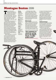
All of the X-Bike’s quick releases must be securely fastened before riding<br />
the bicycle. The quick releases are pictured on the following page in Fig.<br />
1. They are: the front wheel quick release lever (#23), the seat post quick<br />
release lever (#8), the boom tube quick release lever (#9) and, the rear wheel<br />
quick release lever (#30, not on all models). For instructions on operating<br />
the quick release levers, see pages 5-6.<br />
Double check to ensure all bolts and screws are tight.<br />
Make sure that anyone to whom you loan your <strong>Montague</strong> understands<br />
how to work the quick release levers and how to fold and unfold the X-Bike<br />
properly.<br />
The owner is responsible for required normal maintenance services, such<br />
as those listed in the “Maintenance” sections of this booklet (pages 28-31) in<br />
order to keep the bicycle in good operating condition.<br />
Damage or injury resulting from negligence, improper operation, improper<br />
or unauthorized repair or from maintenance, environmental infl uences,<br />
and improper use are not warranted by <strong>Montague</strong> Corporation. <strong>Montague</strong><br />
Corporation excludes incidental and consequential damages.<br />
WARNING<br />
Make sure to read this complete manual before riding your bike. Failure<br />
to do so, or failure to follow its guidelines could lead to serious injury or<br />
death.<br />
1.<br />
2.
4. ASSEMBLY AND ADJUSTMENT<br />
Although your <strong>Montague</strong> is 99% assembled, there are a few steps that must<br />
be completed before it is ready to ride. If you have questions or concerns<br />
about any of these steps, please see a bicycle dealer or contact <strong>Montague</strong>’s<br />
Customer Support Team toll free at (800) 736-5348.<br />
Carefully follow the “Final Assembly Instructions” attached to your bike.<br />
Once you have completed the assembly, read the remainder of this Owner’s<br />
<strong>Manual</strong>.<br />
NEVER ATTEMPT TO RIDE A BICYCLE THAT IS NOT PROPERLY<br />
ASSEMBLED.<br />
Inside your box you will fi nd:<br />
• 1 99% Assembled Bicycle, folded with rear wheel attached<br />
• 1 Saddle with seat post<br />
• 1 Front Wheel<br />
• 1 Small Parts Box which includes:<br />
• 2 Pedals (Right and Left)<br />
• 1 Front Wheel Quick Release<br />
• 1 15 mm Pedal Wrench<br />
Carefully remove the bicycle and all accessories from the box to avoid<br />
scratching the frame. Check the carton for loose parts before discarding.<br />
1. shift levers<br />
2. handlebar<br />
3. brake lever<br />
4. stem<br />
5. saddle<br />
6. head set<br />
7. seat post<br />
8. seat post quick<br />
release<br />
9. boom tube quick<br />
release<br />
10. refl ectors (front<br />
& rear)<br />
11. boom tube<br />
12. spoke refl ectors<br />
(front & rear)<br />
13. tire (front & rear)<br />
14. water bottle mounts<br />
15. seat tube<br />
16. rear brake<br />
17. front brake<br />
18. down tube<br />
19. crank arm<br />
20. seat stay<br />
21. cassette<br />
22. front derailleur<br />
23. front wheel quick<br />
release<br />
24. quick release drop box<br />
3. FIG. 1: PARTS OF YOUR BICYCLE AND LOCATION OF QUICK RELEASES<br />
25. chainstay 28. pedal 30. rear wheel quick release<br />
26. chain wheel 29. rim (front & rear)<br />
27. rear derailleur<br />
3. 4.
4. ASSEMBLY AND ADJUSTMENT<br />
OPERATION OF QUICK RELEASES (FIG. 2):<br />
Since your <strong>Montague</strong> relies on quick releases for folding and general assembly<br />
and adjustment, it is crucial that you fully understand how to operate the<br />
levers.<br />
Great care should be taken when locking the quick release levers on the<br />
bicycle. Failure to properly tighten the quick release levers for the<br />
wheels, seatpost, or frame can result in loss of control and may result<br />
in serious injury or death. If you do not fully understand how to operate<br />
the quick release levers, ask a bicycle mechanic for assistance, or call<br />
<strong>Montague</strong>’s Customer Support Team toll free at (800) 736-5348. Do not ride<br />
your bicycle without all quick releases securely locked.<br />
The quick releases are (See Fig. 1):<br />
4. ASSEMBLY AND ADJUSTMENT<br />
4. Once the lever is securely closed, you should not be able to move it<br />
unless you open it again, Step 1. If you can easily move it, open the<br />
quick release lever again and tighten the nut another half turn clockwise.<br />
Continue with Step 3.<br />
5. If you have adjusted the nut too tightly and cannot push the lever to the<br />
“close” position, open the quick release lever again and turn the nut a<br />
half turn counterclockwise. Continue with Step 3.<br />
Adjusting Nut<br />
CLIX Wheel Release System (standard front wheel quick release<br />
found on bike models prior to 2007) (#23)<br />
The seatpost quick release lever (#8)<br />
The boom tube quick release lever (#9)<br />
The rear wheel quick release lever (#30, not on all models)<br />
1. To release a quick release lever, pull it away from the bike<br />
and towards you until it turns over 180º and the word “open”<br />
is visible facing the outside, away from the bicycle. If your<br />
quick release lever is not marked “open” and “closed”, it is<br />
open when the lever curves away from the bicycle.<br />
2.<br />
1. Tightening<br />
the Adjusting<br />
Nut<br />
Quick Release Lever<br />
The tightness of the lever is adjusted with the nut opposite the<br />
release lever and by rotating the quick release lever. Turn the nut<br />
by hand to adjust the tension while holding the lever stable (Fig. 2).<br />
3. To lock the release lever, push lever up and over towards<br />
the bike frame until it turns over 180º and the word “open”<br />
is no longer visible (Fig. 2), or the lever curves toward the<br />
bicycle. The lever is securely tightened when it leaves an<br />
imprint on the palm of your hand from pushing it closed.<br />
2. Locking the Quick<br />
Release Lever<br />
Fig. 2: Operation of Quick Release Levers<br />
WARNING<br />
Use extreme care when operating Quick Release Levers. Your personal<br />
safety depends on proper and secure operation of the Quick Release<br />
Levers.<br />
5. 6.
4. ASSEMBLY AND ADJUSTMENT<br />
INSTALLING OR ADJUSTING THE SEAT:<br />
1. Loosen seatpost quick release lever (Fig. 3).<br />
2. Insert the seatpost into the seat at least to the minimum insertion line.<br />
CAUTION: Do not raise seat post beyond the minimum insertion line.<br />
To maintain rider safety, at least 2½” of seat post must be in the frame<br />
at all times (Fig. 4).<br />
3. To adjust seat height, loosen the seat post quick release lever (see page<br />
5 for proper operation of quick release levers). Raise or lower the seat<br />
post accordingly. Retighten the quick release lever securely so that<br />
when the quick release lever is closed, the seat post cannot be rotated<br />
in the frame.<br />
Adjust for comfort of the rider. The saddle is properly adjusted when you can<br />
sit on the saddle, and with your knee only slightly bent (approx. 15º), reach the<br />
pedal at its lowest point with the ball of your foot.<br />
4. ASSEMBLY AND ADJUSTMENT<br />
INSTALLING THE PEDALS (FIG. 5):<br />
You will fi nd a pair of pedals in your small parts box. The pedals have different<br />
threads and are stamped “R” for Right and “L” for Left, on the ends of the axle<br />
shaft to differentiate between right and left. Do not try to insert the wrong<br />
pedal into the crank arm as it will strip the threads in the crank.<br />
1. Align the pedal axle with the threaded hole in the respective crank arm<br />
and secure the pedal in the crank by hand.<br />
• The right pedal is installed by turning the pedal axle<br />
clock-wise.<br />
• The left pedal is installed by turning the pedal axle<br />
counterclockwise.<br />
2. After the pedals can no longer be turned by hand, use the 15 mm pedal<br />
wrench (included) and tighten the pedals securely. The shoulder of each<br />
pedal should fi t tightly against the crank arm.<br />
Min.<br />
Insertion<br />
Line<br />
Fig. 3: Seat Post Installation<br />
Fig. 4: Insertion Line<br />
Fig. 5: Pedal Assembly<br />
CAUTION: Always start threading the pedals into the crank by hand to<br />
prevent stripping the threads. Do not ride the bike if pedals are loose.<br />
7. 8.
NOTE: Left and right are determined from riding position on the bicycle.<br />
V-BRAKES (FIG. 6):<br />
To release the brakes:<br />
4. ASSEMBLY AND ADJUSTMENT<br />
1. Pinch the brake arches together<br />
with one hand.<br />
2. Pull the cable guide out and up<br />
while pushing the cable hook<br />
unit down.<br />
3. Release the brake arches,<br />
allowing them to fall open on<br />
either side of the wheel.<br />
Cable<br />
Hook<br />
Unit<br />
Fig. 6: Assembly of Front V-brakes<br />
To attach the brakes:<br />
Use one hand to pinch the brake arches together and level the cable hook unit.<br />
With the other hand, squeeze the end cap into the hook unit.<br />
Release the brake arches and the hook unit will lock into place<br />
Squeeze the brake lever a few times to ensure the brakes are secured in<br />
place.<br />
WARNING<br />
Metal Cable Guide<br />
End Cap<br />
Brake<br />
Arch<br />
Always inspect the brakes before riding to be sure they are functioning<br />
properly. If you are not comfortable with the assembly instructions,<br />
please see a bicycle mechanic or call for assistance. Brakes that are not<br />
properly adjusted may result in loss of control and serious personal injury<br />
or death. NEVER ATTEMPT TO RIDE A BICYCLE WITHOUT PROPERLY<br />
FUNCTIONING BRAKES.<br />
Brakes and Gear System: The brakes and gear system are factory set.<br />
However, new brake and gear cables may stretch. Therefore, please check<br />
brakes and gear system before riding your bicycle. If necessary, adjustments<br />
to brakes and gear system can be made by you (refer to the “Operation of<br />
Gear System’ and “Inspection and Maintenance” sections of this manual ) or<br />
by a bicycle mechanic.<br />
Front Wheel Installation (FIG. 7):<br />
4. ASSEMBLY AND ADJUSTMENT<br />
WARNING<br />
Riding with an improperly adjusted wheel quick release can allow the<br />
wheel to wobble or disengage from the bike, causing damage to the<br />
bicycle, and serious injury or death to the rider.<br />
1. Remove the front wheel quick release unit from the small parts box.<br />
2. Unscrew the adjusting nut from the quick release unit, and remove it and<br />
the corresponding spring from the quick release axle.<br />
3. Insert the quick release unit through the wheel hub with the lever on the<br />
left side of the wheel.<br />
Note: Left and right are determined from riding position on the<br />
bicycle and can be found in one of the following ways:<br />
• If an arrow is embossed or printed on the sidewall of the<br />
tire, the wheel should be positioned so the arrow points in<br />
the direction of rotation while riding the bicycle.<br />
• If the manufacturer’s labels are on the tire, the wheel should<br />
be positioned so they are on the right side of the tire.<br />
4. Put the spring back on the quick release unit and loosely screw on the<br />
adjusting nut, leaving room on either side of the hub for the axle to fi t into<br />
the front fork.<br />
5. Position the wheel in the center of the front fork, keeping the opened<br />
quick release lever on the left side of the bicycle.<br />
6. Guide the axle into the fork slots, being careful not to knock the brake<br />
shoes loose.<br />
7. With axle inserted all the way into the fork slots, center the wheel between<br />
the fork blades.<br />
8. Tighten the adjusting nut until you feel a defi nite resistance in the quick<br />
release lever when you push it ½ the way to closed position.<br />
9. Push the lever all the way to the closed position to lock the wheel<br />
securely in place.<br />
9. 10.
4. ASSEMBLY AND ADJUSTMENT<br />
10. Test the quick release lever. If you can rotate it up and down, it is too<br />
loose.<br />
11. If the quick release is too loose, re-open the lever and tighten the<br />
adjusting nut until you can not rotate the lever in the locked position.<br />
12. Re-engage the brakes (see page 9). Squeeze the brake lever tightly<br />
few times and check that brakes are operating properly.<br />
13. Tires should be infl ated to the pressure indicated on the tire side wall.<br />
If tire does not have enough air, infl ate it using a regulated hand or foot<br />
pump before riding. Do not ride with tires that are not properly infl ated.<br />
Front Fork<br />
Wheel Hub<br />
Adjusting Nut<br />
5. BEFORE EVERY RIDE - CHECKLIST<br />
Your new <strong>Montague</strong> bike is designed and manufactured with the utmost care<br />
and attention to detail. <strong>Montague</strong> utilizes high quality, industry standard<br />
components to compliment our patented, FIT TM frame. We are sure you will<br />
fi nd your bike not only meets your needs, but exceeds them.<br />
If you wish to replace any parts or components on your <strong>Montague</strong>, you do so<br />
at your own risk. <strong>Montague</strong> recommends that all modifi cations to components<br />
and parts be supervised by a trained bicycle technician.<br />
Familiarize yourself with the use of all moving parts on your new bike, including<br />
the wheels, chain and especially, your brakes. <strong>Montague</strong> has specifi cally<br />
chosen an appropriate breaking system for the design of our bikes. The<br />
braking power (ability to stop) varies among different braking systems. If you<br />
wish to change the braking system on your bike <strong>Montague</strong> recommends you<br />
consult a bicycle dealer for appropriate options.<br />
Practice riding your bike at slow speeds in an area with no-traffi c, such as an<br />
empty parking lot, your driveway, or back yard before you attempt to ride in<br />
traffi c, or on trails.<br />
Axle<br />
Quick Release Lever<br />
Tension Spring<br />
WARNING<br />
Avoid contact between your foot or toe clip and the front wheel or fender of<br />
your bike when turning. Doing so may cause loss of control and may result<br />
in serious personal injury. If you experience a frame vibration or “shimmy”<br />
slow your speed immediately and take your bike to a bicycle mechanic.<br />
Fig. 7: Front Wheel Assembly<br />
Removal:<br />
1. Disengage the front brakes. (See page 9).<br />
2. Open the hub quick release by pulling the lever away from the wheel<br />
and turning it 180º.<br />
3. Slip the wheel out of the fork. If the wheel does not slide out easily,<br />
loosen the adjusting nut several turns. Do not force the wheel.<br />
WARNING<br />
This is not a comprehensive maintenance program. <strong>Montague</strong> recommends<br />
that you have your bicycle tuned and safely checked by a bicycle technician<br />
on a regular basis. If you notice any irregularities in your bike and/or its<br />
performance take it to a bike dealer before attempting to ride. Overuse of<br />
any brake system may cause loss of control resulting in personal injury.<br />
11. 12.
5. BEFORE EVERY RIDE - CHECKLIST<br />
Ensure your bicycle is in proper working condition each and every time you<br />
ride. Use the following checklist as a guide.<br />
<br />
Check your brakes. Press each hand lever to ensure the brakes are<br />
moving freely and stop the bike. If your brakes are not working properly DO<br />
NOT ride your bicycle. Practice braking at low speeds before taking your bike<br />
out into high traffic areas or trails.<br />
<br />
Check the attachment of both wheels. Pick the front wheel off the<br />
ground and apply force to the wheel in a downward motion, (Fig. 8). The wheel<br />
should remain securely in place. Grab your wheel and try to move it from side<br />
to side. If there is any movement of the wheel do not ride your bike. Take it<br />
to a bike dealer for service.<br />
When the quick release lever is properly adjusted and in the closed position<br />
you should not be able to rotate the lever in a circular motion (parallel to the<br />
wheel). This is different from the “fl ipping” motion, used to open and close the<br />
quick release lever. Repeat the same steps to check the rear wheel.<br />
<br />
Test the security of the handlebar and stem by attempting to turn the<br />
handlebars in the stem and by twisting them from side to side with the front<br />
wheel locked between your knees (Fig. 9). Make sure that no cables are<br />
stretched or pinched by rotating the handlebars.<br />
Your handlebar and stem control your ability to steer your bike, therefore, if any<br />
part of your handlebar or stem shows signs of damage or fatigue you should<br />
not ride your bike. Once a month check the alignment of your handlebar and<br />
stem with your front wheel. Ensure all stem bolts are tight.<br />
6. FOLDING YOUR MONTAGUE BIKE<br />
Your <strong>Montague</strong> bike is designed for quick folding and unfolding without the<br />
use of tools. The following simple steps should be observed to ensure the<br />
rider’s safety and to prevent damage or scratches when folding or unfolding<br />
the bicycle.<br />
1. Standing on the chain side of your bike, release the brake wire from<br />
the front wheel brake (Fig. 10). To release the brakes, pinch the brake<br />
arches together and swing the cable hook unit down. Push the end cap<br />
and cable guide out of the hook unit. Release the arches.<br />
2. To unlock the front wheel quick release lever swing the lever to the open<br />
position. Hold the adjusting nut in place while turning the quick release<br />
lever counter clockwise 5 or 6 times to release the wheel. Remove the<br />
front wheel from the fork and set it aside (Fig. 11).<br />
Fig. 10: Release of Front Brake<br />
Fig. 9: Checking your<br />
Fig. 11: Removal of the Front Wheel<br />
Fig. 8: Checking your Wheel Handlebar and Stem<br />
13. 14.
6. FOLDING YOUR MONTAGUE BIKE<br />
3. Pull the bike up into the vertical position and stand on the chain side<br />
with the rear tire on the ground between your feet. Open the quick<br />
release lever on top of the boom tube (Fig. 12). Spin it counterclockwise<br />
5 to 6 complete rotations, then with the heal of your hand press<br />
and hold down the quick release to lower quick release nut out of<br />
the quick release drop box while folding the bike with the handlebars<br />
turned away from you so they fold into the rear wheel (Fig. 13). This<br />
is best done by placing your other hand on top of the frame and<br />
pushing away from you.<br />
For extra compactness: open the quick release below the saddle and lower<br />
the saddle all the way down. Then close the quick release below the saddle<br />
(Fig. 14).<br />
Fig. 13: <strong>Folding</strong> the <strong>Montague</strong> Bike<br />
Fig. 12: Open Boom Tube Quick Release<br />
Fig. 14: Final Folded Position of the <strong>Montague</strong> Bike<br />
15. 16.
7. UNFOLDING YOUR MONTAGUE BIKE<br />
1. To unfold the bike place the rear wheel fi rmly on the ground, grasp the<br />
rear wheel with one hand and the handlebar stem with the other and<br />
unfold the bike. When the frame is almost completely unfolded, push<br />
down on the opened boom tube quick release so the quick release nut<br />
enters the quick release drop box. Secure the boom tube quick release<br />
lever by rotating it in the open position clockwise 5 to 6 times (Fig. 15a<br />
& 15b). Lock the quick release lever with the lever pointing towards the<br />
saddle. Make sure the Quick Release End Nut is completely inside the<br />
Quick Release Drop Box. See “Operation of Quick Releases”, page 5.<br />
7. UNFOLDING YOUR MONTAGUE BIKE<br />
4. Adjust the saddle to proper height and lock the quick release lever. The<br />
quick release should be tight enough so that it leaves a mark on the<br />
palm of your hand when closing it (see page 7).<br />
WARNING<br />
If you do not fully understand any of the steps for unfolding your <strong>Montague</strong><br />
bike, be sure to ask your bicycle dealer for assistance, or call <strong>Montague</strong>’s<br />
Customer Support Team toll free at (800) 736-5348.<br />
DO NOT RIDE THE BICYCLE UNLESS ALL FOUR QUICK RELEASES<br />
ARE SECURELY LOCKED!<br />
NOTE: some models do not have rear wheel quick release.<br />
Fig. 15a: Quick Release Operation for Final Assembly<br />
WARNING<br />
Do not use the quick release lever like a wing nut.<br />
Boom Tube<br />
Quick Release Lever<br />
2. Put the front wheel on the bicycle, with the quick release lever positioned<br />
on the non-chain side. Guide the axle into the fork slots and center<br />
the wheel between the fork blades. Hold the quick release lever in the<br />
open position and tighten the adjusting nut so that you feel resistance<br />
half way when you are closing the quick release lever. Close the quick<br />
release lever all the way over to lock the wheel securely. The quick<br />
release should be tight enough that it leaves a mark on the palm of your<br />
hand when closing it. If you can rotate the quick release lever it is too<br />
loose. Reopen the quick release lever and tighten the adjusting nut until<br />
you can’t rotate the lever up and down when the lever is in the locked<br />
position (see page 10, Front Wheel Installation).<br />
Quick Release Axle<br />
Quick<br />
Release<br />
End Nut<br />
Safety Lip<br />
Quick Release<br />
Drop Box<br />
3. To attach the front brakes, pinch the brake arches together and swing<br />
the hook unit up. Push the end cap and cable guide into the hook unit,<br />
allowing the cable to feed through the end of the hook unit. Release the<br />
brake arches and the hook unit will lock into place over the end cap (see<br />
Fig. 15b: Boom Tube Quick Release<br />
page 9, To Attach the Brakes).<br />
17. 18.
8. ROAD SAFETY<br />
• For your safety, always wear a helmet that meets Snell or American<br />
National Standards Institute (Ansi) Z290.4 requirements. In the<br />
event of an accident a helmet can protect you from serious injury<br />
and even death. A bicycle retailer will be happy to assist you in the<br />
selection of a helmet and other useful accessories.<br />
• Obey all traffi c laws. Obey red and green lights, one-way streets,<br />
stop signs, etc.<br />
• Ride with the traffic, not against it. Ride single fi le in a straight line.<br />
• Have a satisfactory signaling device (bell, horn, etc.), to warn of<br />
approach. RIDE DEFENSIVELY (expect the unexpected).<br />
• Give pedestrians the right of way. Do not ride too close to<br />
pedestrians and alert them if you intend to pass from behind.<br />
• Slow down at all street intersections and look to the right and left<br />
before crossing.<br />
• Always use proper hand signals for turning and stopping. Give<br />
signals 100 ft. before stopping or turning and always return both<br />
hands to the handlebars before stopping or turning.<br />
• Watch for cars pulling out into traffic and for sudden opening of car<br />
doors.<br />
• Avoid potholes, drainage grates or other road surface hazards.<br />
Cross railroad tracks at a right angle. Be careful when riding on soft<br />
road edges, gravel, sand and uneven surfaces. Ride slowly and<br />
avoid quick turns when riding on these surfaces.<br />
WARNING<br />
Use your front brake properly to ensure safe, effi cient stopping. To avoid<br />
misuse and potential injury, do not apply sudden or excessive force on<br />
your front brake. To do so may cause your rear wheel to lift off the ground<br />
and/or, your front wheel to slip from under you.<br />
8. ROAD SAFETY<br />
• Never hitch on other vehicles, do not “Stunt” ride or race in traffi c.<br />
Don’t weave in and out of the traffi c or swerve from side to side.<br />
• Never carry other riders or packages, they may obstruct vision or<br />
proper control of the bicycle.<br />
• Before riding, check your brakes. Be sure they are operating<br />
efficiently and that your bicycle is in perfect running condition.<br />
• When riding at night, always use lights, clear light on front and<br />
fl ashing red light on rear, and wear light colored and/or refl ective<br />
clothing. Make sure your refl ectors are intact and visible. Assume<br />
motorists are unable to see you and ride in an appropriately<br />
cautious manner.<br />
• When braking always apply stronger braking pressure to the rear<br />
wheel (right lever). If the front brake pressure (left lever) is applied<br />
too strongly or quickly, the bicycle may fl ip forward. Avoid strong<br />
braking while turning.<br />
CAUTION IN WET WEATHER RIDING<br />
No brakes work as well under wet conditions as they do under dry conditions.<br />
In rainy wet weather, special precautions must be taken to insure safety in<br />
stopping. Proper adjustment and cable lubrication will help, but the major<br />
precaution rests with you. Increased brake pressure is required in wet or<br />
rainy weather and care must be exercised to maintain safety under these<br />
conditions.<br />
Ride slower than normal and apply your brakes sooner than normal<br />
conditions would require.<br />
A crash can put extraordinary stress on bicycle components, causing<br />
them to fatigue prematurely. Components suffering from stress fatigue<br />
can fail suddenly, causing loss of control, or serious injury.<br />
WARNING<br />
Your bicycle is equipped with refl ectors, however, extreme caution is required<br />
when travelling at dusk or night. In addition to keeping your refl ectors<br />
clean, and properly affi xed to your bicycle, you must use headlights<br />
and taillights, in addition to wearing bright, refl ective clothing when riding in<br />
poor lighting conditions. Consult your local bike shop to fi nd accessories<br />
appropriate for your riding needs.<br />
19. 20.
9. OPERATION OF THE GEAR SYSTEM<br />
The multi-gear system provides a means of maintaining a constant pedaling<br />
rate, regardless of road level conditions. This is the most effective cycling<br />
technique to prevent tiring over long distances.<br />
The gears are activated by cables connecting the twist shifters or shift levers<br />
located on the handlebar to the derailleurs.<br />
If your bicycle is equipped with twist shifters, rotating the twist shifters towards<br />
you moves the chain from one chainwheel (or sprocket) to the next larger<br />
chainwheel (or sprocket). Rotating the twist shifters away from you moves<br />
the chain from one chainwheel (or sprocket) to the next smaller chainwheel<br />
(or sprocket).<br />
If your bicycle is equipped with shift levers, pushing the thumb shift lever away<br />
from you moves the chain from one chainring (or sprocket) to the next larger<br />
chainring (or sprocket). Pulling the index fi nger shift lever towards you moves<br />
the chain to the next smaller chainring (or sprocket).<br />
The left shifter controls the front derailleur and the right shifter lever controls<br />
the rear derailleur . To shift, continue pedaling at a steady pace while operating<br />
the shifters and engage the gear you fi nd most comfortable.<br />
For easiest pedaling (while going up-hill or slowly), position the chain over<br />
the smallest chainring in front and the largest sprocket in back. For hardest<br />
pedaling (while going down-hill, or quickly), position the chain over the largest<br />
chainring in front and the smallest sprocket in back.<br />
Pedals and wheels must be turning forward while shifting gears. Never pedal<br />
backward while shifting gears and never force the twist shifters or shift<br />
levers.<br />
9. OPERATION OF THE GEAR SYSTEM<br />
ADJUSTMENT OF THE CABLE TENSION:<br />
If the gear system is not functioning properly, ensure that the rear derailleur<br />
follows each shifting command of the right twist shifter/shift lever. Cable<br />
stretching could affect the function after some time, so that synchronization<br />
may no longer be assured. Check and adjust as follows:<br />
1. Shift the chain to the center of the front chainwheel by turning the crank<br />
forward and shifting the left twist shifter/shift lever.<br />
2. Shift the chain to the outermost/smallest rear sprocket by turning the<br />
right twist shifter all the way away from you, or moving the right shift<br />
lever all the way towards you.<br />
3. While turning the crank forward, rotate the right twist shifter or push the<br />
right shift lever to the next position.<br />
4. The chain should move to the second rear sprocket after a maximum of<br />
one full turn of the wheel. If it stays on the fi rst sprocket, the tension of<br />
the shifting cable must be increased (proceed to Step 6).<br />
5. If the chain jumps across the second sprocket or if it scratches the third<br />
sprocket, the tension of the shifting cable must be decreased<br />
(proceed to Step 6).<br />
6. Cable tension is adjusted<br />
by turning the Cable Adjusting<br />
Barrel, which is located at the<br />
junction of the cable and the<br />
rear derailleur (Fig. 16).<br />
To increase tension turn the<br />
knurled knob counterclockwise,<br />
to decrease tension, turn the<br />
knob clockwise.<br />
21.<br />
If the tension is adjusted according<br />
to the above steps, the chain should<br />
follow all shifting commands on the<br />
twist shifters.<br />
If the gear system still does not<br />
function properly, please contact<br />
a bicycle retailer for assistance.<br />
Cable adjusting<br />
barrel<br />
Fig. 16: Adjustment of Cable Tension<br />
22.
10. ADJUSTMENT OF HANDLEBAR AND SEAT<br />
HANDLEBAR STEM ADJUSTMENT:<br />
Your handlebar’s primary function is to steer and control your bicycle,<br />
therefore proper installation, adjustment and maintenance are crucial for your<br />
enjoyment and safety.<br />
To change the handlebar height, loosen the stem expander bolt two to three<br />
turns, then tap the top of the stem handlebars to the desired height, and<br />
retighten very tightly (175-260 lb.•in or 19.8-29.4Nm). MAKE SURE THE<br />
MINIMUM INSERTION LINE IS NOT SHOWING ABOVE THE HEADSET.<br />
Some bikes are equipped with a stem that has an adjustable rise, or angle.<br />
These bikes require that you tighten the angle adjusting bolt to 150-170 lb.•in<br />
(17-20.3 Nm) after first making sure the teeth are correctly engaged with the<br />
corresponding teeth entered between the teeth of the mating part.<br />
Note: Some bikes are equipped with handlebar stems that are not adjustable<br />
in height.<br />
Test the security of the handlebars in the stem and the stem in the frame, by<br />
attempting to twist the handlebars in the stem and by attempting to turn them<br />
from side to side with the front wheel locked between your knees (Fig. 17). Make<br />
sure there are no cables stretched or pinched by rotating the handlebars.<br />
WARNING<br />
If you are unsure of the safety of your handlebar system, do not attempt<br />
to ride your bike. Never ride your bicycle with the stem raised above the<br />
minimum insertion mark as this may cause loss of control resulting in<br />
personal injury or death. A minimum of 2 3/4 inches (70mm) of the stem<br />
must always remain in the frame.<br />
10. ADJUSTMENT OF HANDLEBAR AND SEAT<br />
SEAT ADJUSTMENT:<br />
Your seat and seatpost are the primary means of support for the rider.<br />
Proper adjustment is important for your comfort and pedaling effi ciency.<br />
Ensure your seat and seatpost are securely tightened in a comfortable<br />
position for your riding style.<br />
Ensure that the seat is secure by attempting to turn the seat and seatpost<br />
in the frame. Grabbing the saddle, attempt to move the front of the saddle<br />
up and down and side to side. If it rotates, is loose, or moves up and down,<br />
tighten the quick release and repeat the test until there is no movement.<br />
(see page 5 for Operation of Quick Release Levers).<br />
Your seat post has a “Minimum Insertion Mark” 2 1/2 inches above the<br />
bottom. When you adjust the height, always make sure this mark is inside<br />
the frame and NOT showing.<br />
WARNING<br />
When adjusting the seatpost ensure the minimum insertion mark remains<br />
inside the frame. A minimum of 2 1/2 inches (64mm) of seatpost must<br />
remain in the frame. Riding with the seat raised above this height may<br />
cause loss of control resulting in personal injury or damage to your bike.<br />
Fig. 17: Hold Wheel and Try to<br />
Turn Handlebar<br />
23. 24.
11. SCHEDULED MAINTENANCE<br />
We recommend that you take your bicycle in to an authorized bicycle dealer<br />
before riding it and then once a year for maintenance so that you can enjoy<br />
your <strong>Montague</strong> bike for as long as possible. Maintenance of your bicycle<br />
should include the following:<br />
Maintenance service by a dealer<br />
1. Crank set: check play, adjust and retighten if necessary.<br />
2. Head set assembly: check play, adjust and tighten if necessary.<br />
3. Brake system: replace brake cables, check brake pads and replace<br />
if necessary, adjust lever play.<br />
4. Gear system: grease shifting cables, check and adjust setting and<br />
indexing function.<br />
5. Wheels: check alignment, realign if necessary. Check and adjust air<br />
pressure.<br />
6. Chain: check, replace if necessary.<br />
7. Tighten mounting bolts on handlebar, saddle, brakes and hubs.<br />
8. Boom Tube quick release box: keep free of debris.<br />
9. Quick releases: check function.<br />
Regular performance of these maintenance services will afford carefree<br />
enjoyment of your <strong>Montague</strong> bike.<br />
WARNING<br />
Failure to properly maintain your bicycle may lead to damage to the bicycle,<br />
or a loss of control resulting in personal injury.<br />
12. INSPECTION AND MAINTENANCE<br />
Regular care preserves the value and safety of your bicycle. You can carry<br />
out the following care and inspection procedures yourself or bring the bicycle<br />
to a dealer for maintenance. We recommend that you do take your bicycle in<br />
to a dealer once a year for maintenance so you can enjoy your <strong>Montague</strong> for<br />
as long as possible.<br />
TOOLS NEEDED FOR MAINTENANCE OF YOUR MONTAGUE BIKE:<br />
• Small adjustable wrench<br />
• Large adjustable wrench<br />
• Set of 4, 5, 6 mm Allen keys<br />
• Medium Phillips screwdriver<br />
• Slip-joint pliers<br />
• Flat thin open end wrench 15mm<br />
• Air pump<br />
• Tire levers<br />
GENERAL INSPECTION: Every week or two tighten all nuts and bolts.<br />
Check all hardware to see that no parts are worn or damaged, that there<br />
is correct fork and frame alignment, and that all components are seated in<br />
proper position.<br />
CLEANING: Clean the frame and all parts regularly with a moist cloth or<br />
sponge. Bicycle shops offer special cleaning agents for easy care.<br />
REFLECTORS: Reflectors should be kept clean, securely fastened and<br />
positioned for bicycle identifi cation at night from front, rear and lateral visibility.<br />
Damaged units should be promptly replaced.<br />
CONTROL CABLES: Replace worn or damaged cables. Do not kink cables.<br />
Cables stretch with use; adjust accordingly. Keep control cable lubricated.<br />
HANDLEBAR/STEERING: On some models, the handlebar stem may be<br />
adjusted for your comfort. The bearing of the fork in the frame (headset)<br />
should rotate easily without play. Adjustment of the headset requires special<br />
tools and should be performed by a bicycle mechanic.<br />
GRIPS: Replace worn grips. Make sure they fi t snugly.<br />
25. 26.
12. INSPECTION AND MAINTENANCE<br />
BRAKES: The brake levers should be easy to operate without too much play.<br />
Too much play will cause insufficient braking power. The play is properly<br />
adjusted if the brake pads meet the rim fully when the brake lever is pulled<br />
one third of the way.<br />
Adjust the brake play by turning the adjusting nuts located at the junction<br />
of the brake cable and brake lever. When you have determined the proper<br />
setting, turn the knurled knob at the shaft of the adjusting bolt all the way<br />
down to the brake lever to lock the brake setting in place.<br />
• The right brake lever controls the rear brake. To tighten<br />
brakes, turn the adjusting nut clockwise. To loosen brakes,<br />
turn the adjusting nut counterclockwise.<br />
• The left brake lever controls the front brake. To tighten<br />
brakes, turn the adjusting nut counterclockwise. Too loosen, turn<br />
the adjusting nut clockwise.<br />
Note: Left and right controls are reversed on bicycles sold in some countries.<br />
Check brake pads regularly for wear and make sure they are properly toed in.<br />
Viewed from the side, the brake pads should be exactly at the height of the<br />
rim and slightly toed in the direction of the rotation of the wheel. The brake<br />
pads must display tread. When the tread is worn down, the brake pads must<br />
be replaced.<br />
For safety reasons, the brake cables must be replaced every 12 months. This<br />
should be included in the annual maintenance service by a certifi ed bicycle<br />
repair and maintenance shop.<br />
ALIGNMENT: If the bicycle does not align properly, immediately bring to a<br />
bicycle mechanic or call <strong>Montague</strong>’s Customer Support Team toll free at (800)<br />
736-5348.<br />
12. INSPECTION AND MAINTENANCE<br />
WHEELS: Make sure the quick release lever on the front wheel is properly<br />
closed and the axle nuts, or quick release lever on the rear wheel are tight.<br />
Wheels should be centered in fork or dropouts. Irregular noise from the wheels<br />
or the brakes touching the rim indicates that the wheel requires maintenance.<br />
Wheels should be checked regularly for spoke tightness and true alignment.<br />
WHEEL ALIGNMENT: Wheels should rotate smoothly without wobbling from<br />
side to side. Check the bearing play of the hubs by lifting the bicycle and<br />
spinning the wheel. The wheel should continue to spin for several rotations<br />
and fi nally cease spinning. To check the play of the hubs: try to move the<br />
rim from side to side between the fork. During this test, no substantial play<br />
should exist. If you detect play or if the wheel is difficult to turn, the hub<br />
bearings must be adjusted. Please contact a bicycle mechanic to have the<br />
hub bearings adjusted.<br />
RIMS: The rims must be smooth and without cracks, breaks, or bulges. Check<br />
that they are smooth on the inside to prevent puncturing the inner tube.<br />
SPOKES: Check spoke tension regularly. Approximately the same tension<br />
should be applied to all spokes. If there is minor loosening of the spokes, you<br />
may tighten the nipples, but it is recommended that you take the bicycle to a<br />
bicycle mechanic. If you detect a loose spoke or if the rim has a side play of<br />
more than 4mm, immediately have the wheel trued by a technician. Riding<br />
with loose spokes may cause the wheel to fail, resulting in serious injury<br />
or death.<br />
TIRES: Maintaining proper infl ation levels of your tires ensures a smooth,<br />
effi cient and safe ride. Make sure that the tires are infl ated according to<br />
pressure indicated on tire sidewall. Improper tire pressure will cause excessive<br />
wear, causing premature replacement. A foot or frame pump should be used.<br />
Pressurized, unregulated pumps should not be used.<br />
The tire should be properly seated in the rim and the fi tting of the tire bead<br />
and rim bead should be checked. If the tube is pinched between the tire and<br />
the rim, it will explode when infl ated. Ensure that the tire is not cracked or<br />
unevenly worn. Check for bulges. Check that the valve is straight in the rim.<br />
Irregular tires should be replaced immediately.<br />
27. 28.
12. INSPECTION AND MAINTENANCE<br />
CHAIN: Check frequently for damage and stretch and replace if necessary.<br />
Lubricate several times each season and after each washing or ride in the<br />
rain. Use a lightweight, all-purpose oil, being careful to oil each link. Chain<br />
specifi c oil is available from any bicycle shop. The chain must be replaced<br />
after a maximum of 1250 miles. This requires special tools and should be<br />
performed by a certifi ed bicycle mechanic.<br />
CHAINRINGS: Replace if chainring teeth are bent or damaged. Keep<br />
chainrings tight on crank.<br />
CRANKS & PEDALS: Crank assembly should turn freely without side play.<br />
Check the bearing play of the cranks by grasping the end of the crank near<br />
the pedal thread and trying to wiggle it laterally. If you detect play, have it<br />
corrected by a dealer.<br />
Keep locknut tight and keep bearings clean and well adjusted. Check crank<br />
bolt or nut (depending on axle type) regularly to make sure crank arms stay<br />
tight.<br />
Replace bent cranks immediately! Do not attempt to straighten.<br />
Replace pedals if bearings are tight or frozen and if thread is lost or badly<br />
worn. Keep pedal bearings lubricated.<br />
REFLECTORS: Your refl ectors are an important safety feature of your bike,<br />
Do not remove them. Every three months, check the nuts and bolts holding the<br />
front, rear, pedal and wheel refl ectors and make sure that they are tight. Also<br />
check the alignment of the front and rear refl ectors, their refl ective surfaces<br />
should be perpendicular to the ground. The rear refl ector should be at least<br />
three inches below the top of the seat. KEEP REFLECTORS CLEAN AT ALL<br />
TIMES.<br />
12. INSPECTION AND MAINTENANCE<br />
FRONT DERAILLEUR ADJUSTMENT: (FIG. 18)<br />
The derailing cage must be positioned high enough to clear the chain<br />
wheels while shifting. If an adjustment is necessary, loosen the frame clamp<br />
and reposition accordingly. When re-tightening the frame clamp bolt, make<br />
sure the curvature of the derailing cage is concentric to the curvature of the<br />
chainwheel and that the derailing cage is in line with the chainwheel.<br />
The front derailleur should shift smoothly and easily between the<br />
chainwheels. If the front derailleur does not shift correctly, it can be adjusted<br />
as follows:<br />
1. Place left lever all the way forward, or twist shift all<br />
the way back, and adjust screw “H” to center derailing<br />
cage and chain over the large chainwheel.<br />
2. Move left shift lever all the way back or twist shift all the way<br />
forward and adjust limiting screw “L” so the derailing cage<br />
and chain are centered over the smaller chainwheel.<br />
3. Loosen the cable anchor nut and pull all slack out of the cable<br />
through the anchor bolt. Re-tighten the cable anchor bolt securely.<br />
These adjustments will limit the inward and outward movement of the<br />
derailing cage so the chain will not derail to the left of the inside chainwheel<br />
or to the right of the outside chainwheel.<br />
Derailing<br />
Cage<br />
2.5 mm<br />
Limiting<br />
Screw<br />
“ H”<br />
Frame<br />
Clamp<br />
Bolt<br />
Cable Anchor<br />
Nut<br />
Small Chainwheel<br />
Fig. 18: Front Derailleur Adjustments<br />
29. 30.
12 . INSPECTION AND MAINTENANCE<br />
REAR DERAILLEUR ADJUSTMENT (FIG 19):<br />
With the right shift lever all the way back or the twist shift all the way forward,<br />
the rear derailleur should position the chain on the smallest rear sprocket<br />
with no trace of slack in the control cable.<br />
If the chain does not reach the smallest sprocket:<br />
Adjust limiting screw “H” (moving it out, away from the derailleur housing)<br />
allowing the necessary additional outward travel of the derailleur.<br />
Once adjusted, limiting screw “H” should be moved to bottom against the<br />
derailleur housing, stopping any additional outward travel of the derailleur<br />
and preventing the chain from running off the smallest sprocket.<br />
If there is slack in the cable:<br />
Turn the barrel adjustment counterclockwise to remove slack. If the slack<br />
is not taken up, or if the derailleur does not have a barrel adjuster, a cable<br />
adjustment is necessary. Loosen the cable-fi xing bolt freeing the cable. Pull<br />
the cable tight and retighten bolt securely.<br />
With the right shift lever all the way forward, or the twist shift all the way back,<br />
the derailleur should position the chain on the largest rear sprocket.<br />
If the chain does not reach the largest sprocket:<br />
Adjust limiting screw “L” to allow for<br />
this and position it to bottom against<br />
the derailleur housing to prevent any<br />
additional inward travel of the<br />
rear derailleur. This will stop the<br />
chain from running off the inside<br />
of the large rear sprocket.<br />
Optional Accessories:<br />
13. ACCESSORIES FOR YOUR MONTAGUE<br />
<strong>Folding</strong> Pedals: <strong>Folding</strong> pedals will reduce the folded width of the bicycle<br />
by four inches and are available to fi t on all models.<br />
Carrying Case: A water resistant 420 Denier nylon carrying case is<br />
available. It has an over-the-shoulder strap and an inner pocket for the front<br />
wheel. See your dealer for more details.<br />
Additional Accessories: More custom <strong>Montague</strong> accessories are also<br />
available, and since your <strong>Montague</strong> uses standard parts and components,<br />
you can customize your bike in numerous ways. Check out your local bike<br />
dealer’s selection of parts and accessories.<br />
INSTALLATION OF RACKS: <strong>Montague</strong> does not manufacture rear racks,<br />
but recommends you use a seat post mount rack. Contact your local<br />
bicycle retailer for further details.<br />
Guide Pulley<br />
Cable<br />
Adjusting<br />
Barrel<br />
Adjusting<br />
Screw “L”<br />
Adjusting<br />
Screw “H”<br />
Cable<br />
fi xing Bolt<br />
Tension Pulley<br />
Fig 19: Rear Derailleur Adjustment<br />
31. 32.
14. MONTAGUE CORPORATION LIMITED WARRANTY<br />
<strong>Montague</strong> Corporation warrants each new <strong>Montague</strong> bicycle frame against<br />
defects in workmanship and materials for the lifetime of the original owner.<br />
<strong>Montague</strong> Corporation also warrants all original parts, excluding suspension<br />
forks, for a period of one year from the date of purchase. Forks shall be<br />
covered by the stated warranty of their original manufacturers. Paint and<br />
decals are warranted for one year. This warranty is expressly limited to<br />
the repair or replacement of a defective frame, fork, or defective part and is<br />
the sole remedy of the warranty. This warranty is not transferable from the<br />
original owner.<br />
Claims must be made through an authorized <strong>Montague</strong> dealer. Proof<br />
of purchase is required. In addition, a warranty registration card must be<br />
completed and received by <strong>Montague</strong> Corporation before a warranty claim<br />
may be processed.<br />
This warranty does not cover normal wear and tear, improper assembly,<br />
damage or failure due to accident, misuse, abuse or neglect, follow-up<br />
maintenance, or installation of parts or accessories not originally intended<br />
or compatible with the bicycle as it was sold. Modifi cation of the frame or<br />
components shall void this warranty.<br />
<strong>Montague</strong> Corporation shall not be responsible for incidental or consequential<br />
damages. Some states do not allow the exclusion of incidental or consequential<br />
damages, so the above exclusion may not apply to you.<br />
Labor charges for parts changeovers are not covered by the warranty.<br />
This warranty gives the consumer specifi c legal rights, and those rights may<br />
vary from place to place. This warranty does not effect the statutory rights<br />
of the consumer.<br />
HUMMER and all related and distinctive vehicle model body and grille designs are General Motors<br />
Trademarks used under license to <strong>Montague</strong> Corporation.<br />
© 2004 <strong>Montague</strong> Corporation, Cambridge, MA 02238 USA. <strong>Montague</strong> is a registered Trademark of the<br />
<strong>Montague</strong> Corporation.<br />
Component specifi cations vary by country and are subject to change without notice. All <strong>Montague</strong> bicycles<br />
are covered under one or more patents or patents pending.<br />
33.<br />
<strong>Montague</strong> Corporation<br />
P.O. Box 381118<br />
Cambridge, MA 02238<br />
Toll Free Phone # (800) 736-5348<br />
International Customers Call (617) 491-7200<br />
© 2004 <strong>Montague</strong> Corporation, Cambridge, MA, USA
Name:<br />
Mailing Address:<br />
Place of Purchase:<br />
MONTAGUE BICYCLE WARRANTY REGISTRATION CARD<br />
Location - City: State: Date of Purchase / /<br />
Purchase Price: Bicycle Color: Model Name:<br />
Serial #: Frame Size: User’s Sex: M / F Age:<br />
Used of Folded <strong>Montague</strong> Bicycle (if more than one applies, number by priority)<br />
Store in home Commute Airline Travel Sailboat Powerboat<br />
Car Trunk Private Plane RV Other:<br />
Is use: Personal Government/Military Corporate<br />
What type of riding do you mainly use your <strong>Montague</strong> Bicycle for?<br />
City Bike Trails/paths Off-road Touring<br />
How did you hear about <strong>Montague</strong> Bicycles?<br />
Bicycle Dealer Consumer shows/Expos Friend Internet<br />
Other:<br />
Advertisement (specify where):<br />
News Article (specify where):<br />
Comments:
From:<br />
MONTAGUE CORPORATION<br />
P.O. Box 381118<br />
Cambridge, MA 02238