Chain Link Fence Manufacturers Institute Product Manual
Chain Link Fence Manufacturers Institute Product Manual
Chain Link Fence Manufacturers Institute Product Manual

Create successful ePaper yourself
Turn your PDF publications into a flip-book with our unique Google optimized e-Paper software.
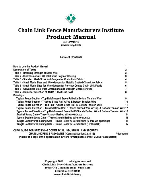
<strong>Chain</strong> <strong>Link</strong> <strong>Fence</strong> <strong>Manufacturers</strong> <strong>Institute</strong><br />
<strong>Product</strong> <strong>Manual</strong><br />
CLF-PM0610<br />
(revised July, 2011)<br />
Table of Contents<br />
How to Use the <strong>Product</strong> <strong>Manual</strong> 1<br />
Description of Terms 2<br />
Table 1 - Breaking Strength of Steel Wire 3<br />
Table 2 -Thickness of ASTM F668 Fabric Polymer Coating 3<br />
Table 3 - Standard Mesh Sizes and Gauges for <strong>Chain</strong> <strong>Link</strong> Fabric 4<br />
Table 4 - Small Mesh Sizes and Wire Gauges for Metallic Coated <strong>Chain</strong> <strong>Link</strong> Fabric 5<br />
Table 5 - Small Mesh Sizes for Wire Gauges for Polymer Coated <strong>Chain</strong> <strong>Link</strong> Fabric 6<br />
Table 6 - Galvanized Steel Post Dimensions and Strength Characteristics 7<br />
Table 7 - Guide for Selection of ASTM F 1043 Line Post 8<br />
Drawings<br />
Typical <strong>Fence</strong> Section - Top Rail/Trussed Brace Rail with Bottom Tension Wire 9<br />
Typical <strong>Fence</strong> Section - Trussed Brace Rail w/Top & Bottom Tension Wire 10<br />
Typical <strong>Fence</strong> Elevation – Top Rail/Trussed Brace Rail w/ Bottom Tension Wire 11<br />
Typical <strong>Fence</strong> Elevation – Trussed Brace Rail; 3 Stands Barbed Wire w/ Top & Bottom Tension Wire 12<br />
Typical <strong>Fence</strong> Elevation –Top Rail/Trussed Brace Rail 3 Stands Barbed Wire & Bottom Tension Wire 13<br />
Typical Swing Gate – Three Strands Barbed Wire (OPTIONAL) 14<br />
Typical Double Swing Gate – Three Strands Barbed Wire (OPTIONAL) 15<br />
Single Cantilevered Sliding Gate – Round Posts w/ Barbed Wire (6’ thru 22’ openings) 16<br />
Single Cantilevered Sliding Gate – Round Posts w/ Barbed Wire (10’ thru 30’) 17<br />
CLFMI GUIDE FOR SPECIFYING COMMERCIAL, INDUSTRIAL, AND SECURITY<br />
CHAIN LINK FENCE AND GATES ( Contract Section 32 31 13)<br />
Addendum<br />
(Note: For a copy of this specification in Word format please contact CLFMI Headquarters)<br />
Copyright 2011. All rights reserved<br />
<strong>Chain</strong> <strong>Link</strong> <strong>Fence</strong> <strong>Manufacturers</strong> <strong>Institute</strong><br />
10015 Old Columbia Road Suite B215<br />
Columbia, MD 21046<br />
www.chainlinkinfo.org
CHAIN LINK FENCE MANUFACTUTERS INSTITUTE PRODUCT MANUAL<br />
(CLF‐PM2445)<br />
The purpose of this manual is to provide chain link fence technical information for general knowledge,<br />
system design or the development of a commercial/industrial/security chain link fence specification.<br />
HOW TO USE THE CLFMI PRODUCT MANUAL<br />
a. Familiarize yourself with the content of the CLFMI product manual.<br />
b. The product manual includes drawings of the four standard chain link fence designs plus swing<br />
gate, cantilever slide gate and fitting/assembly details.<br />
c. Review the different chain link fabric configurations and gauges to ensure the best selection of<br />
the mesh size and wire gauge for the application.<br />
d. Prior to designing a security fence system read the CLFMI “Security Fencing Recommendations<br />
SFR2445”.<br />
e. Select the type of fabric for the application; galvanized (ASTM A392), aluminum coated (ASTM<br />
A491), zinc ‐5% mischmetal alloy (ASTM F1345) or polymer coated (ASTMF 668).<br />
f. Review the framework Dimensions and Strength Characteristics Table # 6 and Guide for<br />
Selection of Line Post, Table # 7 to select the post that best suits the application, (ASTM F1043<br />
and ASTM F1083). Make sure to take into consideration wind load particularly if the fence is 8 ft.<br />
high or greater using 1 in. mesh or less. Use the CLFMI “<strong>Chain</strong> <strong>Link</strong> <strong>Fence</strong> Wind Load Guide for<br />
the Selection of Line Post and Line Post Spacing WLG2445” for a fence requiring a structural<br />
framework design due to wind load.<br />
g. For polymer coated fabric or systems choose an ASTM color from ASTM F934.<br />
h. Thoroughly review and understand the chain link ASTM standards; those reference above as<br />
well as; chain link terminology (F552), fittings and tie wire (F626), barbed wire (A121 and F665),<br />
barbed tape (F1910 and F1911) tension/coil spring wire (A824 and F1644), swing gates (F900),<br />
horizontal slide gates (F1184), automated vehicular gates (F2200), and chain link installation<br />
(F567).<br />
i. The CLFMI manual includes a CSI formatted chain link fence specification, “Commercial,<br />
Industrial and Security <strong>Chain</strong> <strong>Link</strong> <strong>Fence</strong> and Gates, Section 32 31 13” for use in designing and<br />
specifying a chain link fence system.<br />
j. For light industrial/commercial applications select framework form ASTM F1043 Table 4<br />
“Summary of Requirements for Light Industrial/Commercial <strong>Fence</strong> Framework”.<br />
k. All phases of chain link fence installation are covered in detail within the Specification 32 31 13,<br />
Part 3.<br />
1
DESCRIPTION OF TERMS<br />
A short list of descriptive terms: (See ASTM F552, “Standard Terminology Relating to <strong>Chain</strong> <strong>Link</strong><br />
Fencing” for a complete list.)<br />
a. <strong>Chain</strong> link fabric – A fencing material consisting of wire helically wound and interwoven in such a<br />
manner as to provide a continuous mesh without knots or ties except in the form of knuckling or<br />
twisting at the top and bottom of the mesh to form the fabric selvage.<br />
b. Selvage‐The top and bottom edge finish on woven chain link formed by joining adjacent pairs of<br />
wire pickets. The selvage may be knuckled or twisted.<br />
c. Knuckled selvage* refers to bending the adjacent pairs of wire back into a tight loop.<br />
d. Twisted selvage* refers to twisting the adjacent pairs of wire together in a close helix of 1 ½<br />
machine turns, which is equivalent to three full twists.<br />
e. Mesh size – The minimum clear distance between the wires forming the parallel sides of the<br />
mesh.<br />
f. Terminal post – A post to which the chain link fabric is terminated using specific fittings; end<br />
post, corner post, gate post and pull post (a terminal post used to accommodate a grade or<br />
placed at intervals on long stretches of fence).<br />
g. Line post‐ Intermediate posts set no greater than 10 feet on center between the terminal posts.<br />
h. See drawing Typical <strong>Fence</strong> Section for details of various fence fittings; tension bar, truss rod,<br />
tension band, brace band, rail end and barb arm.<br />
KNUCKLE SELVAGE*<br />
TWIST SELVAGE*<br />
*Adapted, with permission from the Annual Book of Standards, copyright ASTM International, 100 Barr Harbor Drive, West Conshohocken, PA<br />
19248<br />
2
TABLE 1<br />
BREAKING STRENGTH OF STEEL WIRE<br />
6 gauge ‐0.192” [4.88 mm] 2170 lbf [9650 N]<br />
9 gauge‐ 0.148” [3.76 mm] 1290 lbf [5740 N]<br />
11 gauge‐ 0.120” [3.05 mm] 850 lbf [3780 N]<br />
11 ½ gauge‐ 0.113” [2.87 mm] 750 lbf [3340 N]<br />
12 gauge‐ 0.105” [2.67 mm] 650 lbf [2890 N]<br />
14 gauge‐ 0.080” [2.03 mm] 380 lbf [1690 N]<br />
TABLE 2 THICKNESS OF ASTM F668 FABRIC POLYMER COATING<br />
Minimum/Maximum Class 1 & Class 2a Class 2b<br />
Minimum @ any point 0.015 in. [0.38 mm] 0.006 in. [0.15 mm]<br />
Maximum @ any point 0.025 in. [0.64 mm] 0.010 in. [0.25 mm]<br />
3
TABLE 3 STANDARD 1” & LARGER MESH SIZES AND GAUGES FOR CHAIN LINK FABRIC<br />
ASTM A392 galvanized, ASTM A491 aluminum coated, ASTM F1345 zinc‐5%aluminummischmetal<br />
alloy, ASTM F668 polymer coated<br />
Size of mesh Gauge* Nominal Diameter Recommended Usage<br />
2 1/8” [54 mm] 11 ½ 0.113” [2.87 mm] Residential<br />
2” [50 mm] 11 0.120” [3.05 mm] Residential/light commercial<br />
2” [50 mm] 9 0.148” [3.76 mm] Residential /commercial/ind.<br />
2” [50 mm] 6 0.192” [4.88 mm] Commercial/ind./security<br />
1 ¾” [44 mm] 11 0.120” [3.05 mm] Tennis court<br />
1 ¾” [44 mm] 9 0.148” [3.76 mm] Heavy commercial/industrial<br />
1 ¾” [44 mm] 6 0.192” [4.88 mm] Security<br />
1 ¼” [32 mm] 11 0.120” [3.05 mm] Residential/swimming pool<br />
1 ¼” [32 mm] 9 0.148” [3.76 mm] Heavy industrial /Security<br />
1” [25 mm] 11 0.120” [3.05 mm] Industrial<br />
1” [25 mm] 9 0.148” [3.76 mm] Heavy industrial/ Security<br />
*polymer coated core wire gauge is specified gauge reference not the coated finished diameter<br />
4
Figure 1. Mesh Dimensions for small security chain link fabric**<br />
Mesh Size S Height H Width W<br />
3/8 in. [9 mm] 3/4 in. [19 mm] 3/4 in. [19 mm]<br />
1/2 in. [13 mm] 15/16 in. [24 mm] 15/16 in. [24 mm]<br />
5/8in. [16 mm] 1 1/8 in. [29 mm] 1 1/8 in. [29 mm]<br />
** Figure 1 adapted with permission from the Annual Book of ASTM Standards, copyright ASTM<br />
International, 100 Barr Harbor Drive, West Conshohocken, PA 19248<br />
TABLE 4 SMALL MESH SIZES AND WIRE GAUGES FOR METALLIC COATED CHAIN LINK FABRIC<br />
ASTM A392 galvanized, ASTM A491 aluminum coated, ASTM F1345 zinc‐5%aluminum‐mischmetal alloy<br />
Size of mesh Gauge Nominal Diameter Recommended Usage<br />
5/8” [16 mm] 11 1/2 0.113” [2.87 mm] Security / anti‐climb<br />
5/8” [16 mm] 11 0.120 [3.05 mm] Security / anti‐climb<br />
5/8” [16 mm] 9 0.148 [3.76 mm] Security /anti‐climb<br />
1/2” [12.7 mm] 11 1/2 0.113 [2.87 mm] Security/anti‐climb<br />
1/2” [12.7 mm] 11 0.120 [3.05 mm] Security/anti‐climb<br />
1/2” [12.7 mm] 9 0.148 [3.76 mm] Security/anti‐climb<br />
3/8” [10 mm] 11 1/2 0.113 [2.87 mm] Security /anti‐climb<br />
3/8” [10 mm] 11 0.120 [3.05 mm] Security /anti‐climb<br />
5
TABLE 5 SMALL MESH SIZES AND WIRE GAUGES FOR POLYMER COATED CHAIN LINK FABRIC ASTM F668<br />
Size of mesh *Core Wire Gauge Nominal Diameter Recommended Usage<br />
5/8” [16 mm] 14 0.080” [2.03 mm] Industrial/anti‐climb<br />
5/8” [16 mm] 12 0.105” [2.67 mm] Light security/anti‐climb<br />
5/8” [16 mm] 11 0.120” [3.05 mm] Security / anti‐climb<br />
5/8” [16 mm] 9 0.148” [3.76 mm] High Security /anti‐climb<br />
1/2” [12.7 mm] 14 0.080” [2.03 mm] Light security/anti‐climb<br />
1/2” [12.7 mm] 12 0.105” [2.67 mm] Security/anti‐climb<br />
1/2” [12.7 mm] 11 0.120” [3.05 mm] High Security/anti‐climb<br />
1/2” [12.7 mm] 9 0.148” [3.76 mm] Max. Security/anti‐climb<br />
3/8” [10 mm] 14 0.080” [2.03 mm] Security/anti‐climb<br />
3/8” [10 mm] 12 0.105” [2.67 mm] Security/anti‐climb<br />
3/8” [10 mm] 11 0.120” [3.05 mm] High Security /anti‐climb<br />
*polymer coated wire gauge is specified by the core wire gauge not the finished coated diameter<br />
6
TABLE 6<br />
GALVANIZED STEEL POST DIMENSIONS AND STRENGTH CHARACTERISITCS<br />
ASTM F1043 Group IA Regular Strength Grade ASTM F1083 30,000 psi yield steel schedule 40 pipe<br />
Trade Decimal O.D. Pipe wall Section Min. Yield Max Bending Calculated Load (lbs)<br />
Reference Equivalent Thickness Weight Modulus x Strength = Moment 10' Free Cantilever<br />
O.D. inches (mm) inches (mm) lb./ft. (kg/m) inches³ (mm³) x psi (MPa) = Lb.In. Supported 4' 6'<br />
1 3/8" 1.315 33.40 0.133 3.38 1.68 2.5 0.1328 3.37 x 30000 205 = 3985 133 83 55<br />
1 5/8" 1.660 42.16 0.140 3.56 2.27 3.38 0.2346 5.96 x 30000 205 = 7038 235 147 98<br />
1 7/8" 1.900 48.26 0.145 3.68 2.72 4.05 0.3262 8.29 x 30000 205 = 9786 326 204 136<br />
2 3/8" 2.375 60.33 0.154 3.91 3.65 5.43 0.5606 14.24 x 30000 205 = 16819 561 350 234<br />
2 7/8" 2.875 73.03 0.203 5.16 5.80 8.62 1.0640 27.03 x 30000 205 = 31921 1064 665 443<br />
3 1/2" 3.500 88.90 0.216 5.49 7.58 11.28 1.7241 43.79 x 30000 205 = 51723 1724 1078 718<br />
4" 4.000 101.60 0.226 5.74 9.12 13.56 2.3939 60.80 x 30000 205 = 71816 2394 1496 997<br />
4 1/2" 4.500 114.30 0.237 6.02 10.80 16.05 3.2145 81.65 x 30000 205 96435 3214 2009 1339<br />
5 9/16" 5.563 141.30 0.258 6.55 14.63 21.77 5.4511 138.46 x 30000 205 = 163533 5451 3407 2271<br />
6 5/8" 6.625 168.28 0.280 7.11 18.99 28.23 8.4958 215.79 x 30000 205 = 254873 8496 5310 3540<br />
8 5/8" 8.625 219.08 0.322 8.18 28.58 42.49 16.8091 426.95 x 30000 205 = 504274 16809 10506 7004<br />
ASTM F1043 Group IA Intermediate Strength Grade ASTM F1083 50,000 psi yield steel schedule 40 pipe<br />
Trade Decimal O.D. Pipe wall Section Min. Yield Max Bending Calculated Load (lbs)<br />
Reference Equivalent Thickness Weight Modulus x Strength = Moment 10' Free Cantilever<br />
O.D. inches (mm) inches (mm) lb./ft. (kg/m) inches³ (mm³) x psi (MPa) = Lb.In. Supported 6' 15'<br />
6 5/8" 6.625 168.28 0.280 7.11 18.99 28.23 8.4958 215.79 x 50000 345 = 424789 14160 5900 2360<br />
8 5/8" 8.625 219.08 0.322 8.18 28.58 42.49 16.8091 426.95 x 50000 345 = 840457 28015 11673 4669<br />
ASTM F1043 Group IA High Strength 83000 Grade ASTM F1083 83,000 psi yield steel schedule 40 pipe<br />
Trade Decimal O.D. Pipe wall Section Min. Yield Max Bending Calculated Load (lbs)<br />
Reference Equivalent Thickness Weight Modulus x Strength = Moment 10' Free Cantilever<br />
O.D. inches (mm) inches (mm) lb./ft. (kg/m) inches³ (mm³) x psi (MPa) = Lb.In. Supported 6' 15'<br />
1 5/8" 1.660 42.16 0.140 3.56 2.27 3.38 0.2346 5.96 x 83000 572 = 19471 649 270 108<br />
1 7/8" 1.900 48.26 0.145 3.68 2.72 4.05 0.3262 8.29 x 83000 572 = 27075 903 376 150<br />
2 3/8" 2.375 60.33 0.154 3.91 3.65 5.43 0.5606 14.24 x 83000 572 = 46532 1551 646 258<br />
2 7/8" 2.875 73.03 0.203 5.16 5.80 8.62 1.0640 27.03 x 83000 572 = 88315 2944 1227 491<br />
3 1/2" 3.500 88.90 0.216 5.49 7.58 11.28 1.7241 43.79 x 83000 572 = 143100 4770 1987 795<br />
4" 4.000 101.60 0.226 5.74 9.12 13.56 2.3939 60.80 x 83000 572 = 198691 6623 2760 1104<br />
ASTM F1043 Group IC Electric Resistant Welded 50,000 psi yield steel pipe<br />
Trade Decimal O.D. Pipe wall Section Min. Yield Max Bending Calculated Load (lbs)<br />
Reference Equivalent Thickness Weight Modulus x Strength = Moment 10' Free Cantilever<br />
O.D. inches (mm) inches (mm) lb./ft. (kg/m) inches³ (mm³) x psi (Mpa) = Lb.In. Supported 4' 6'<br />
1 5/8" 1.660 42.16 0.111 2.82 1.84 2.74 0.1962 4.98 x 50000 345 = 9810 327 204 136<br />
1 7/8" 1.900 48.26 0.120 3.05 2.28 3.39 0.2810 7.14 x 50000 345 = 14050 468 293 195<br />
2 3/8" 2.375 60.33 0.130 3.30 3.12 4.64 0.4881 12.40 x 50000 345 = 24405 814 508 339<br />
2 7/8" 2.875 73.03 0.160 4.06 4.64 6.91 0.8778 22.30 x 50000 345 = 43890 1463 914 610<br />
3 1/2" 3.500 88.90 0.160 4.06 5.71 8.50 1.3408 34.06 x 50000 345 = 67042 2235 1397 931<br />
4" 4.000 101.60 0.160 4.06 6.57 9.78 1.7820 45.26 x 50000 345 = 89098 2970 1856 1237<br />
4 1/2" 4.500 114.30 0.160 4.14 7.42 11.04 2.2859 57.99 X 50000 345 = 114295 3810 5486 1587<br />
ASTM F1043 Group II Rolled Formed C line post 50,000/60,000 psi yield steel (strength shown is about the major axis)<br />
Dimensions<br />
Dimensions Material Thickness Weight Section Modulus Min. Yield Strength Max. Bending Cantilever Load<br />
Inches<br />
Metric (mm) Inches (mm) lb./ft. (kg/m) inches³ (mm³) psi (Mpa) Moment Lb.In. 4' 6'<br />
1.875 x 1.625 47.6 x 41.2 0.121 3.10 2.40 3.39 0.395 10.03 50000 345 19750 411 274<br />
2.250 x 1.700 57.2 x 43.2 0.121 3.10 2.78 4.13 0.506 12.85 50000 345 25300 527 351<br />
3.250 x 2.500 82.5 x 63.5 0.130 3.30 4.50 6.70 1.083 27.51 60000 414 64980 1354 903<br />
ASTM F1043 Group III Hot Rolled H-Beam line post 50,000 psi yield steel (strength shown is about the major axis)<br />
Dimensions<br />
Dimensions Material Thickness Weight Section Modulus Min. Yield Strength Max. Bending Cantilever Load<br />
Inches<br />
Metric (mm) Inches (mm) lb./ft. (kg/m) inches³ (mm³) psi (Mpa) Moment Lb.In. 4' 6'<br />
2.250 x 1.700 57.2 x 43.2 0.125 3.18 3.26 4.85 0.661 16.76 50000 345 33050 689 459<br />
7
TABLE 7<br />
GUIDE FOR SELECTION OF ASTM F1043/F1083 LINE POST<br />
<strong>Fence</strong> Fabric Height Group IA Group IC Group II<br />
ASTM F1083 Elec. Resistance Rolled Formed<br />
Sch. 40 Pipe Welded Pipe C‐Section<br />
Min/Max O.D. Min/Max O.D. Min. Max.<br />
up to 6' 0" 1.900 ‐ 3.500" 1.900 ‐ 3.500" 1.875x1.625” 2.25x1.70”<br />
over 6' 0" to 8' 0" 2.375 ‐ 4.000" 2.375 ‐ 4.000" 1.875x1.625” 3.25x2.50”<br />
over 8 ' 0" to 10' 0'' 2.875 ‐ 6.625" 2.875 ‐ 4.000" 2.25x1.70” 3.25x2.50”<br />
over 10' 0" to 12' 0" 2.875 ‐ 6.625" 2.875 ‐ 4.000" 3.25x2.50” N/A<br />
over 12' 0" to 14' 0" 3.500 ‐ 6.625" 3.500 ‐ 4.500" N/A<br />
Post size ranges based on mesh size, wire gauge, location, icing, wind speed, wind load<br />
Consult the CLFMI “<strong>Chain</strong> <strong>Link</strong> <strong>Fence</strong> Wind Load Guide for the Selection of Line Post and Line<br />
Post Spacing (WLG 2445)”<br />
Pipe terminal posts are generally one size larger in outside diameter than the line posts<br />
Group IV alternative products are available; require manufacturer to provide documentation,<br />
dimensions, strength calculations and compliance certification to ASTM F1043.<br />
8
CHAIN LINK FENCE MANUFACTURERS INSTITUTE GUIDE FOR<br />
SPECIFYING<br />
COMMERCIAL, INDUSTRIAL AND SECURITY CHAIN LINK FENCE AND<br />
GATES (CLFS 2445)<br />
PART 1 GENERAL<br />
1.1 RELATED DOCUMENTS<br />
CONTRACT SECTION 32 31 13<br />
A. DIVISION 01 - GENERAL REQUIREMENTS: Drawings, quality, product and<br />
performance requirements, general and supplemental conditions apply as applicable<br />
to the project and project documents.<br />
1.2 SUMMARY<br />
A. This Section includes materials applicable for commercial/industrial and security<br />
chain link fence and gates. <br />
[delete products not applicable]<br />
1. Galvanized steel coated chain link fabric<br />
2. Aluminum coated steel chain link fabric<br />
3. Polymer coated steel chain link fabric<br />
4. Zinc 5% Aluminum alloy coated steel chain link fabric<br />
5. Galvanized steel framework and fittings<br />
6. Polymer coated galvanized steel framework and fittings<br />
7. Gates: swing and cantilever slide<br />
8. Barbed wire<br />
9. Barbed tape<br />
10. Installation<br />
B. Related Project Contract Sections: [delete sections not applicable]<br />
1. 01 33 13 Certificates<br />
2. 01 33 23 Shop Drawings, product data<br />
3. 01 43 13 <strong>Manufacturers</strong> Qualifications<br />
4. 01 43 23 Installer Qualifications<br />
5. 01 45 00 Quality Control<br />
6. 01 65 00 <strong>Product</strong> Delivery Requirements<br />
7. 01 66 00 <strong>Product</strong> Storage and Handling Requirements<br />
8. 03 30 53 Miscellaneous Cast in Place Concrete<br />
9. 25 50 00 Integrated automation pertinent to gate operator access control<br />
10. 26 01 02 Electrical distribution as it relates to gate operators and accessories<br />
11. 31 22 19 Finish Grading<br />
32 31 13 <strong>Chain</strong> <strong>Link</strong> <strong>Fence</strong> and Gates - 1
1.3 REFERENCES<br />
[delete references not applicable]<br />
A. ASTM A121 Specification for Metallic-Coated Carbon Steel Barbed Wire<br />
B. ASTM A392 Specification for Zinc-Coated Steel <strong>Chain</strong>-<strong>Link</strong> <strong>Fence</strong> Fabric<br />
C. ASTM A491 Specification for Aluminum-Coated Steel <strong>Chain</strong>-<strong>Link</strong> Fabric<br />
D. ASTM A780 Standard Practice for Repair of Damaged and Uncoated Areas of Hot-<br />
Dip Galvanized Coatings<br />
E. ASTM A824 Specification for Metallic-Coated Steel Marcelled Tension Wire for<br />
Use With <strong>Chain</strong> <strong>Link</strong><br />
F. ASTM F552 Standard Terminology Relating to <strong>Chain</strong> <strong>Link</strong> Fencing<br />
G. ASTM F567 Standard Practice for Installation of <strong>Chain</strong> <strong>Link</strong> <strong>Fence</strong><br />
H. ASTM F626 Specification for <strong>Fence</strong> Fittings<br />
I. ASTM F668 Specification for Polymer Coated <strong>Chain</strong> <strong>Link</strong> <strong>Fence</strong> Fabric<br />
J. ASTM F900 Specification for Industrial and Commercial Swing Gates<br />
K. ASTM F934 Specification for Standard Colors for Polymer-Coated <strong>Chain</strong> <strong>Link</strong><br />
L. ASTM F1043 Specification for Strength and Protective Coatings of Metal Industrial<br />
<strong>Chain</strong> <strong>Link</strong> <strong>Fence</strong> Framework<br />
M. ASTM F1083 Specification for Pipe, Steel, Hot-Dipped Zinc-Coated (Galvanized)<br />
Welded, for <strong>Fence</strong> Structures<br />
N. ASTM F1184 Specification for Industrial and Commercial Horizontal Slide Gates<br />
O. ASTM F1345 Specification for Zinc-5% Aluminum-Mischmetal Alloy-Coated Steel<br />
<strong>Chain</strong>-<strong>Link</strong> <strong>Fence</strong> Fabric<br />
P. ASTM F1664 Specification for Poly (Vinyl Chloride) (PVC) and Other Conforming<br />
Organic Polymer-Coated Steel Tension Wire Used with <strong>Chain</strong>-<strong>Link</strong> <strong>Fence</strong><br />
Q. ASTM F1665 Specification for Poly (Vinyl Chloride) (PVC) and Other Conforming<br />
Organic Polymer-Coated Steel Barbed Wire Used with <strong>Chain</strong>-<strong>Link</strong> <strong>Fence</strong><br />
R. ASTM F1910 Specification for Long Barbed Tape Obstacles<br />
32 31 13 <strong>Chain</strong> <strong>Link</strong> <strong>Fence</strong> and Gates - 2
S. ASTM F1911 Standard Practice for Installation of Barbed Tape<br />
T. ASTM F2200 Specification for Automated Vehicular Gate Construction<br />
U. CLFMI SFR2445, Security <strong>Fence</strong> Recommendations<br />
V. CLFMI WLG2445, <strong>Chain</strong> <strong>Link</strong> <strong>Fence</strong> Wind Load Guide for the Selection of Line<br />
Post and Line Post Spacing<br />
W. Federal Specification RR-F-191/3E Fencing, Wire and Post, Metal (<strong>Chain</strong>–<strong>Link</strong><br />
<strong>Fence</strong> Posts, Top Rails and Braces)<br />
X. UL 325 Door, Drapery, Gate, Louver and Window Operators<br />
1.4 SUBMITTALS<br />
A. Shop drawings: Site plan showing layout of fence location with dimensions,<br />
location of gates and opening size, cleared area, elevation of fence and gates, details of<br />
attachments and footings.<br />
B. Certifications: <strong>Manufacturers</strong> material certifications in compliance with current<br />
ASTM specifications.<br />
C. Domestic certifications: Material certifications, Made in U.S.A., Buy American Act<br />
or Buy America when required.<br />
D. Specification Changes: May not be made after the date of bid.<br />
1.5 QUALITY ASSURANCE<br />
A. Manufacturer: Company operating in the United States having U.S. manufacturing<br />
facility/facilities specializing in manufacturing chain link fence products with at<br />
least 5 years experience.<br />
B. <strong>Fence</strong> contractor: Company with demonstrated successful experience installing<br />
similar projects and products in accordance with ASTM F567 and have at least 5<br />
years experience.<br />
C. Tolerances: Current published edition of ASTM specifications tolerances apply.<br />
ASTM specification tolerances supersede any conflicting tolerance.<br />
1.6 DELIVERY, STORAGE AND HANDLING<br />
A. Delivery: Deliver products to site per contract requirements.<br />
B. Storage: Store and protect products off the ground when required.<br />
32 31 13 <strong>Chain</strong> <strong>Link</strong> <strong>Fence</strong> and Gates - 3
PART 2 – PRODUCTS<br />
2.1 MANUFACTURERS<br />
A. Framework, posts, rails, pipe for gates: [list selected CLFMI manufacturers]<br />
B. Fabric, fittings, gates and accessories: [list selected CLFMI manufacturers]<br />
2.2 CHAIN LINK FABRIC<br />
A. Steel <strong>Chain</strong> <strong>Link</strong> Fabric: __in. mesh, __gauge ___high per ASTM____, top<br />
selvage__ bottom selvage__ [List height or heights] [select ASTM coating<br />
specification designation and Class, mesh size and wire gauge (see Table 1),<br />
top/bottom selvage and color when applicable] [delete fabric specifications not<br />
selected] <br />
1. Zinc-Coated Steel Fabric: ASTM A392 hot dipped galvanized before or<br />
after weaving.<br />
a. Class 1 - 1.2 oz/ft² (366 g/m²)<br />
b. Class 2 - 2.0 oz/ft² (610 g/m²) [available 9 and 6 gauge]<br />
2. Aluminum–Coated Steel Fabric (Aluminized): ASTM A491<br />
3. Zinc-5% Aluminum-Mischmetal Alloy Coated Steel Fabric: ASTM F1345<br />
a. Class 1 – 0.6 oz/ft² (183 g/m²)<br />
b. Class 2 – 1.0 oz/ft² (305 g/m²)<br />
4. Polymer Coated Steel Fabric: ASTM F668, the wire gauge specified for<br />
polymer-coated wire is that of the metallic coated steel core wire<br />
a. Class 1 extruded<br />
b. Class 2a extruded and adhered<br />
c. Class 2b fused and adhered<br />
d. Color: [dark green] [olive green] [brown] [black] in compliance with<br />
ASTM F934<br />
5. Fabric selvage:<br />
Standard fabric selvage for 2 in (50 mm) mesh 72 in. (1.8 m) high and<br />
over is knuckle finish at one end, twist at the other, K&T.<br />
Fabric less than 72 in (1.8 m), knuckle finish top and bottom, K&K.<br />
[Specify K&K for added safety for playfield and park applications]<br />
Mesh sizes less than 2 in. (50 mm) have a knuckle selvage for both top and<br />
bottom, K&K.<br />
32 31 13 <strong>Chain</strong> <strong>Link</strong> <strong>Fence</strong> and Gates - 4
[Table 1: select the chain link fabric mesh size and wire gauge**]<br />
Mesh Size 6 gauge 9 gauge 11 gauge 12 gauge*<br />
Inches (mm) 0.192 in. 0.148 in. 0.120 in. 0.105 in.<br />
(4.88 mm) (3.76 mm) (3.05 mm) (2.67 mm)<br />
2 (50.8) A A NA N/C<br />
1 3/4 (44.5) A A Tennis court fabric N/C<br />
1 1/4 (31.8) N-M A A N/C<br />
1 (25.4) N-M A A N/C<br />
5/8 (15.8) N-M A A A<br />
1/2 (12.7) N-M A A A<br />
3/8 (9.5) N-M N-M A A<br />
Wire breakload lbf 2170 1290 850 650<br />
Wire breakload N 9650 5740 3780 2890<br />
“A”= available, “NA”= generally not a commercial/ind./security mesh, “N/M”= not<br />
manufactured, “N/C”= not in compliance with ASTM and not applicable<br />
*12 gauge polymer coated core wire only<br />
**See CLFMI <strong>Product</strong> <strong>Manual</strong> Tables for complete listing of mesh sizes and gauges<br />
2.3 STEEL FENCE FRAMEWORK<br />
A. Round steel pipe and rail: ASTM F1043 Group IA Table 3 Heavy Industrial<br />
<strong>Fence</strong> Framework, schedule 40 galvanized pipe per ASTM F1083. Exterior zinc<br />
coating Type A, interior zinc coating Type A.<br />
Regular Grade, Intermediate<br />
Strength Grade, High Strength 83000 Grade.<br />
1. Line post: [Refer to Table 2] <br />
2. End, Corner, Pull post: [Refer to Table 2] <br />
3. Top, brace, bottom and intermediate rails, 1.660 in. (42.2 mm) OD, 2.27 lb/ft<br />
[3.38 kg/m]<br />
B. Round steel pipe and rail: ASTM F1043 Group IC Table 3 Heavy Industrial<br />
<strong>Fence</strong> Framework. Exterior zinc coating Type B, interior coating Type B or<br />
Type D.<br />
1. Line post: [Refer to Table 2] <br />
2. End, Corner, Pull post: [Refer Table 2] <br />
3. Top, brace, bottom and intermediate rails, 1.660 in. (42.2 mm) OD, 1.84 lb/ft<br />
[2.74 kg/m]<br />
C. Rolled-Formed line posts and rail: ASTM F1043 Group II Table 3 Heavy<br />
Industrial <strong>Fence</strong> Framework. Zinc coating Type A.<br />
1. Line post dimensions: [Refer to Table 2] <br />
2. Top, brace, bottom and intermediate rails: 1.625 x 1.25 in. (41.2 x 31.7<br />
mm), 1.35 lb/ft (2.01kg/m).<br />
32 31 13 <strong>Chain</strong> <strong>Link</strong> <strong>Fence</strong> and Gates - 5
[1.660 in (42.2 mm) OD round pipe rail can be used with the rolled formed<br />
post] < select ASTM F1043 Group IA or IC rail ><br />
D. Hot-Formed H-line post: ASTM F1043 Group III Table 3 Heavy Industrial<br />
<strong>Fence</strong> Framework. Zinc coating Type A. Line post size [Refer to Table 2]<br />
<br />
1. Top, brace, bottom and intermediate rails: 1.660 in. (42.2 mm) OD <br />
E. Alternative product: ASTM F1043 Group IV Table 3 Heavy Industrial <strong>Fence</strong><br />
Framework. Alternative products are available; require manufacture to provide<br />
documentation, dimensions, strength calculations and certification to ASTM<br />
F1043criteria.<br />
[When specifying light industrial/commercial fence refer to ASTM F1043 Table 4,<br />
Light Industrial/Commercial <strong>Fence</strong> Framework. Round posts Group IC-L, Rolled<br />
formed posts Group II-L, Hot-formed posts Group III-L and Alternate posts Group<br />
IV-L.]<br />
[Use Table 2 to aid in the selection of the line post]<br />
Minimum line post size arrived at by reviewing ASTM F1043, Federal Specification RR/F<br />
191-3E and calculating the post size and spacing using the <strong>Chain</strong> <strong>Link</strong> <strong>Fence</strong> Wind Load<br />
Guide for the Selection of Line Post and Line Post Spacing, WLG2445 taking into<br />
consideration the fence height, mesh size, wire gauge, location, icing, and expected wind gust.<br />
Terminal posts are round pipe generally one size larger than the typical round line post<br />
TABLE 2<br />
<strong>Fence</strong> Fabric Height Group IA Group IC Group II<br />
ASTM F1083 Elec. Resistance Rolled Formed<br />
Sch. 40 Pipe Welded Pipe C‐Section<br />
Min/Max O.D. Min/Max O.D. Min. Max.<br />
up to 6' 0" 1.900 ‐ 3.500" 1.900 ‐ 3.500" 1.875x1.625” 2.250x1.700”<br />
over 6' 0" to 8' 0" 2.375 ‐ 4.000" 2.375 ‐ 4.000" 1.875x1.625” 3.250x2.500”<br />
over 8 ' 0" to 10' 0'' 2.875 ‐ 6.625" 2.875 ‐ 4.000" 2.250x1.700” 3.250x2.500”<br />
over 10' 0" to 12' 0" 2.875 ‐ 6.625" 2.875 ‐ 4.000" 3.250x2.500” N/A<br />
over 12' 0" to 14' 0" 3.500 ‐ 6.625" 3.500 ‐ 4.500" N/A<br />
Consult the CLFMI <strong>Chain</strong> <strong>Link</strong> <strong>Fence</strong> Wind Load Guide for the Selection of Line Post and Line<br />
Post Spacing (WLG2445)<br />
32 31 13 <strong>Chain</strong> <strong>Link</strong> <strong>Fence</strong> and Gates - 6
[FRAMEWORK WIND LOAD CAUTION: <strong>Fence</strong>s containing windscreens or<br />
privacy slats and fences greater than 8 feet (2.4 m) in height using 1 in. (25 mm) mesh<br />
or smaller require a wind load force strength analysis for post size and post spacing.<br />
A <strong>Fence</strong> Post Wind Load Calculator is available at www.chainlinkinfo.org, “<strong>Chain</strong><br />
<strong>Link</strong> <strong>Fence</strong> Wind Load Guide for the Selection of Line Post and Line Post Spacing,<br />
WLG 2445” ]<br />
D. Polymer Coated Framework: Polymer coated framework shall have a [PVC]<br />
[Polyolefin] [Polyester] coating fused and adhered to the exterior zinc coating of<br />
the post or rail. PVC and polyolefin coatings shall have minimum thickness 10-mils<br />
(0.254 mm), polyester coating minimum thickness 3 mils (0.0076 mm) per ASTM<br />
F1043. Color to match fabric [dark green] [olive green] [brown] [black] per<br />
ASTM F934.<br />
2.4 TENSION WIRE<br />
A. Metallic Coated Steel Marcelled Tension Wire: 7 gauge (0.177 in.) (4.50 mm)<br />
marcelled wire complying with ASTM A824 [Match coating type to that of the<br />
chain link fabric] <br />
1. Type I Aluminum–Coated (Aluminized) 0.40 oz/ft² (122 g/m²)<br />
2. Type II Zinc-Coated Class 4 - 1.2 oz/ft² (366 g/m²)<br />
3. Type II Zinc-Coated Class 5 - 2.0 oz/ft² (610 g/m²)<br />
4. Type III Zinc-5% Aluminum-Mischmetal Alloy Coated Steel Fabric<br />
Class 1 – 0.6 oz/ft² (183 g/m²) Class 2 - 1.0 oz/ft² (305 g/m²)<br />
B. Polymer Coated Steel Tension Wire: 7 gauge (0.177 in.) (4.50 mm) wire<br />
complying with ASTM F1664. Wire gauge specified is the core wire gauge.<br />
[Match coating class and color to that of the chain link fabric] <br />
1. Class 1, extruded<br />
2. Class 2a, extruded and adhered<br />
3. Class 2b, fused and adhered,<br />
2.5 BARBED WIRE<br />
A. Metallic Coated Steel Barbed Wire: Comply with ASTM A121, Design Number<br />
12-4-5-14R, double 12-½ gauge (0.099 in.) (2.51 mm) twisted strand wire, with 4<br />
point 14 gauge (0.080 in.) (2.03 mm) round barbs spaced 5 inches (127 mm) on<br />
center. Match coating type to that of the chain link fabric. <br />
1. Coating Type A - Aluminum-Coated (Aluminized): Strand wire coating<br />
Type A - 0.30 oz/ft² (90 g/m²) with aluminum alloy barbs.<br />
2. Coating Type Z - Zinc-coated: Strand wire coating Type Z, Class 3, 0.80<br />
oz/ft² (254 g/m²), barb coating 0.70 oz/ft² (215g/m²)<br />
32 31 13 <strong>Chain</strong> <strong>Link</strong> <strong>Fence</strong> and Gates - 7
B. Polymer Coated Barbed Wire: Comply with ASTM F1665, 0.80 in (2.03 mm)<br />
double twisted strand wire; zinc coated four point, 14 gauge (0.080 in.) (2.03 mm)<br />
barbs spaced 5 inches (127 mm) on center [Match strand wire coating class and<br />
color to the chain link fabric] [Barbs are not polymer coated] <br />
1. Class 1, extruded<br />
2. Class 2a, extruded and adhered<br />
3. Class 2b fused and adhered<br />
2.6 BARBED TAPE<br />
Stainless Steel Long Barbed Tape: Comply with ASTM F1910. [Based on the<br />
security level required select the design configuration from the table listed in<br />
ASTM F1910] [ Insert description, barbed tape material, coil diameter, core<br />
wire gauge and material when applicable, barb clusters per loop, coil loops,<br />
coil loop spacing, coil length, attachment points]<br />
2.7 FITTINGS<br />
A. Tension and Brace Bands: Galvanized pressed steel complying with ASTM F626,<br />
minimum steel thickness of 12 gauge (0.105 in.) (2.67 mm), minimum width of 3/4<br />
in. (19 mm) and minimum zinc coating of 1.20 oz/ft² (366 g/m²). [Bands supplied<br />
with 5/16 in. (7.94 mm) or 3/8 in. (9.53 mm) galvanized steel carriage bolts]<br />
B. Terminal Post Caps, Line Post Loop Tops, Rail and Brace Ends, Boulevard Clamps,<br />
Rail Sleeves: In compliance to ASTM F626, pressed steel galvanized after<br />
fabrication having a minimum zinc coating of 1.20 oz/ft² (366 g/m²).<br />
C. Truss Rod Assembly: In compliance with ASTM F626, 3/8 in. (9.53 mm) diameter<br />
steel truss rod with a pressed steel tightener, minimum zinc coating of 1.2 oz/ft²<br />
(366 g/m²), assembly capable of withstanding a tension of 2,000 lbs. (970 kg).<br />
D. Tension Bars: In compliance with ASTM F626. Galvanized steel one-piece length 2<br />
in. (50 mm) less than the fabric height. Minimum zinc coating 1.2 oz. /ft² (366<br />
g/m²). [select bar size]<br />
1. Bars for 2 in. (50 mm) and 1 ¾ in. (44 mm) mesh shall have a minimum cross<br />
section of 3/16 in. (4.8 mm) by 3/4 in. (19 mm).<br />
2. Bars for 1 in. (25 mm) mesh shall have a cross section of 1/4 in. (6.4 mm) by 3/8<br />
in. (9.5 mm).<br />
3. Bars for small mesh 3/8 in. (10 mm), 1/2 in. (13 mm) and 5/8 in. (16 mm) shall<br />
be attached (sandwiched) to the terminal post using a galvanized steel strap having<br />
a minimum cross section of 2 in. (51 mm) by 3/16 in. (4.8 mm) with holes spaced<br />
15 in. (381 mm) on center to accommodate 5/16 in. (7.9 mm) carriage bolts which<br />
are to be thru bolted thru the strap the mesh and thru the terminal post.<br />
32 31 13 <strong>Chain</strong> <strong>Link</strong> <strong>Fence</strong> and Gates - 8
E. Barbed Wire Arms: In compliance with ASTM F626, pressed steel galvanized after<br />
fabrication, minimum zinc coating of 1.20 oz. /ft² (366 g/m²), capable of supporting<br />
a vertical 250 lb (113 kg) load. [Type I – three strand 45 degree (0.785 rad) arm]<br />
[Type II – three strand vertical arm] [Type III - V shaped six strand arm]<br />
F. Polymer Coated Color Fittings: In compliance with ASTM F626. Polymer coating<br />
minimum thickness 0.006 in. (0.152 mm) fused and adhered to zinc coated fittings<br />
[Match color to fence system]<br />
2.8 TIE WIRE and HOG RINGS<br />
Tie Wire and Hog Rings: Galvanized minimum zinc coating 1.20 oz/ft² (366 g/m²)<br />
9 gauge (0.148) (3.76 mm) steel wire in compliance with ASTM F626. [9 gauge<br />
aluminum alloy hog rings available for metallic coated fabric] [lighter gauge<br />
steel wire may be used on lighter gauge mesh, see ASTM F626] [polymer<br />
coated; match the coating, class and color to that of the chain link fabric]<br />
2.9 SWING GATES<br />
A. Swing Gates: [single] [double] ___ opening ___ by ___ ft. high. Galvanized steel<br />
welded fabrication in compliance with ASTM F900. Gate frame members 1.900 in.<br />
OD (48.3 mm) [ASTM F1043 Group IA F1083<br />
schedule 40 pipe] [ASTM F1043 Group IC pipe] Frame members spaced no<br />
greater than 8 ft. (2440 mm) apart vertically and horizontally. Welded joints<br />
protected by applying zinc-rich paint in accordance with ASTM Practice A780.<br />
Positive locking gate latch fabricated of 5/16 in. (7.9 mm) thick by 1 ¾” (44.45<br />
mm) pressed steel galvanized after fabrication. Galvanized malleable iron or heavy<br />
gauge pressed steel post and frame hinges. Match gate fabric to that of the fence<br />
system. Gateposts ___OD, ___lb/ft [ASTM F1043 Group IA ASTM F1083<br />
schedule 40 pipe] [ASTM F1043 Group IC pipe] [Select the gatepost outside diameter from<br />
table 2.9 B> [Polymer coated gate frames and gateposts; match the coating<br />
type and color to that specified for the fence framework. Moveable parts such<br />
as hinges, latches and drop rods may be field coated using a liquid polymer<br />
touch up] [electrically operated gates must comply with ASTM F2200 and<br />
UL325]<br />
32 31 13 <strong>Chain</strong> <strong>Link</strong> <strong>Fence</strong> and Gates - 9
[Gate post size per ASTM F900]<br />
Gate fabric height up to and including 6 ft. (1.2m)<br />
Gate leaf width<br />
Post Outside Diameter<br />
up to 4 ft. (1.2 m) 2.375 in. (60.3 mm)<br />
over 4 ft. to 10 ft. (1.2 to 3.05 m) 2.875 in. (73.0 mm)<br />
over 10 ft. to 18 ft. (3.05 to 5.5 m) 4.000 in. (101.6 mm)<br />
Gate fabric height over 6 ft. to 12 ft. (1.2 to 2.4m)<br />
Gate leaf width<br />
up to 6 ft. (1.8 m) 2.875 in. (73.0 mm)<br />
over 6 ft. to 12 ft. (1.8 to 3.7 m) 4.000 in. (101.6 mm)<br />
over 12 ft. to 18 ft. (2.4 to 5.5 m) 6.625 in. (168.3 mm)<br />
over 18 ft. to 24 ft. (5.5 to 7.3 m) 8.625 in. (219.1 mm)<br />
2.10 HORIZONTAL SLIDE GATES<br />
A. Type I-Overhead Slide Gates: In compliance with ASTM F1184 Type I. Gate<br />
framing to be of welded construction, minimum 1.900 in. OD (48.3 mm) pipe<br />
members. [ASTM F1043 Group IA ASTM F 1083<br />
sch 40 pipe] [ASTM F1043 Group IC pipe] Framing members to be spaced no<br />
more than 8 ft. (2440 mm) apart horizontally and vertically. Welded joints are to be<br />
protected by applying zinc-rich paint in accordance with ASTM Practice A780.<br />
Positive locking latch, 5/16 in. (7.9 mm) thick by 1 ¾ in. (44.45 mm) pressed steel,<br />
galvanized after fabrication. Galvanized steel drop bars to be provided with double<br />
gates. <strong>Chain</strong> link fabric to match the fence system. Manufacturer’s standard<br />
overhead beam/structure, track, rollers and accessories designed to support the load<br />
of the gate panel taking into consideration wind load and possible icing. The<br />
support beam/structure to be galvanized or receive proper corrosion protection.<br />
Gateposts to be ___OD _____lb/ft <br />
Post size for gate openings up to and including 10 ft. (3.05 m) shall be 2.875 in<br />
OD (73 mm)<br />
Openings greater than 10 ft. (3.05 m) up to 24 ft. (7.3 m) shall be 4.000 in. OD<br />
(101.6 mm)<br />
Openings greater than 24 ft. (7.3 m) up to 40 ft. (12.2 m) shall be double 4.000<br />
in. OD (101.6 mm)<br />
in compliance with [ASTM F1043 Group IA F 1083<br />
schedule 40 pipe] [ASTM F1043 Group IC pipe] .<br />
B. Cantilever Slide Gates: In compliance with ASTM F1184 Type II<br />
1. Class 1-External Roller Design: Horizontal top and bottom steel pipe<br />
“track” members to be 2.375 in. OD (60.3 mm), vertical and internal members<br />
1.900 in. O.D. in compliance with <br />
[ASTM F1043 Group IA 1083 sch 40 pipe] [ASTM F1043 Group IC pipe.]<br />
Gate frame to be fabricated by welding, vertical and horizontal members located<br />
no greater than 8 ft. (2440 mm) apart. The length of back frame support section<br />
32 31 13 <strong>Chain</strong> <strong>Link</strong> <strong>Fence</strong> and Gates - 10
shall be a minimum of 40% of the opening. Welded joints are to be protected by<br />
applying zinc-rich paint in accordance with ASTM Practice A780. Gates<br />
designed to open or close by applying an initial pull force no greater 40 lbs.<br />
(18.14 kg). Match chain link fabric to that of the fence system. Positive locking<br />
latch fabricated galvanized pressed steel. Galvanized steel drop bars provided<br />
with double gates. Gateposts, 4.000 in. OD (101.6 mm) ___lb/ft [ASTM F1043 Group IA ASTM F1083 sch<br />
40 pipe] [ASTM F1043 Group IC pipe]. Provide safety protective guards for<br />
the top and bottom external rollers.<br />
2. Class 2-Internal Roller Design: Select material: [aluminum alloy<br />
extrusion] [ASTM F 1043 Group IA, ASTM F 1083 schedule 40 pipe]<br />
[ASTM F 1043 Group IC pipe] Gate frame fabricated by welding, vertical<br />
and horizontal members located no greater than 8 ft. (2440 mm) apart. The<br />
length of back frame support section shall be a minimum of 40% of the<br />
opening. Class 2 cantilever slide gates to comply with the performance<br />
deflection criteria listed in ASTM F1184. Gates designed to open or close<br />
by applying an initial pull force no greater than 40 lbs. (18.14 kg). Internal<br />
truck assemblies designed to handle the forces required for gate size opening<br />
and height. Match chain link fabric to that of the fence system. Gateposts,<br />
4.000 in. O.D. (106.1 mm) ___lb/ft [ASTM F1043 Group IA ASTM F1083 schedule 40 pipe] [ASTM<br />
F1043 Group IC pipe].<br />
[Internal roller cantilever designs vary by manufacturer and material]<br />
a. [Steel Pipe Frame Design: Match the specification of Class 1<br />
cantilever slide gate. Securely bolt an extruded aluminum<br />
enclosed track designed to accommodate internal roller<br />
assemblies to the top horizontal member]<br />
b. [Aluminum Frame Design: Aluminum rectangular members<br />
of various shapes and wall thickness per manufacturers design<br />
based on gate opening and height. Top horizontal member to<br />
be one-piece extruded section having an integral internal track<br />
to accommodate truck assemblies.]<br />
C. [Polymer coated horizontal slide gates and posts shall match the coating type<br />
and color as that specified for the fence framework.] <br />
D. [Electrically operated gates and accessories must be manufactured and<br />
installed to comply with the safety requirements of ASTM F2200 and UL 325]<br />
2.11 CONCRETE<br />
Concrete for post footings shall have a 28-day compressive strength of 2,500 psi. (17.2<br />
MPa).<br />
32 31 13 <strong>Chain</strong> <strong>Link</strong> <strong>Fence</strong> and Gates - 11
PART 3 EXECUTION<br />
3.1 CLEARING FENCE LINE<br />
Clearing: Surveying, clearing, grubbing, grading and removal of debris for the fence<br />
line or any required clear areas adjacent to the fence <br />
[Surveying, clearing, grubbing, grading and removal of debris for the fence line<br />
or any required clear areas adjacent to the fence is included in the earthwork<br />
contractor’s contract under the provisions of Division 31 - Earthwork.]<br />
[Surveying, clearing, grubbing, grading and removal of debris for the fence line<br />
or any required clear areas adjacent to the fence is not included in the<br />
earthwork contractor’s contract and is the responsibility of the fence contractor<br />
in accordance with the provisions of Division 31 - Earthwork.] The contract<br />
drawings indicate the extent of the area to be cleared and grubbed.<br />
3.2 FRAMEWORK INSTALLATION<br />
A. Posts: Posts shall be set plumb in concrete footings in accordance with ASTM<br />
F567. Minimum footing depth, 24 in. (609.6 mm) plus an additional 3 in. (76.2<br />
mm) for each 1 ft. (305 mm) increase in the fence height over 4 ft. (1220 mm).<br />
Minimum footing diameter four times the largest cross section of the post up to<br />
4.00” (101.6mm) O.D. and three times the largest cross section of post greater than<br />
4.00” (101.6mm). O.D. Gate posts require larger footings; minimum requirements<br />
are listed in ASTM F567. [Site soil conditions,<br />
local frost depth, fence height and wind load may require larger diameter or deeper<br />
footings] Top of post concrete footing to be [at grade ] [6 inches (152 mm) below<br />
grade] crowned to shed water away from the<br />
post. Line posts installed at intervals not exceeding 10 ft. (3.05 m) on center.<br />
B. Top rail: When specified, install 21 ft. (6.4 m) lengths of rail continuous thru the<br />
line post or barb arm loop top. Splice rail using top rail sleeves minimum 6 in. (152<br />
mm) long. [if specifying F1043 light industrial/commercial framework swedged<br />
rail may be used in lieu of sleeves] The rail shall be secured to the terminal post by<br />
a brace band and rail end. Bottom rail or intermediate rail shall be field cut and<br />
secured to the line posts using boulevard bands or rail ends and brace bands.<br />
[<strong>Fence</strong>s 12 feet (3.66 m) high or higher require mid rail]<br />
C. Terminal posts: End, corner, pull and gate posts shall be braced and trussed for<br />
fence 6 ft. (1.8 m) and higher and for fences 5 ft. (1.5 m) in height not having a top<br />
rail. The horizontal brace rail and diagonal truss rod shall be installed in accordance<br />
with ASTM F567.<br />
D. Tension wire: Shall be installed 4 in. (101.6 mm) up from the bottom of the fabric.<br />
<strong>Fence</strong>s without top rail shall have a tension wire installed 4 in. (101.6 mm) down<br />
32 31 13 <strong>Chain</strong> <strong>Link</strong> <strong>Fence</strong> and Gates - 12
3.3 CHAIN LINK FABRIC INSTALLATION<br />
<strong>Chain</strong> <strong>Link</strong> Fabric: Install fabric to [outside] [inside] of the framework. Attach<br />
fabric to the terminal post by threading the tension bar through the fabric; secure the<br />
tension bar to the terminal post with tension bands and 5/16 in. (7.94 mm) carriage<br />
bolts spaced no greater than 12 inches (304.8mm) on center. Small mesh fabric less<br />
than 1 in. (25 mm), attach to terminal post by sandwiching the mesh between the<br />
post and a vertical 2 in. wide (50mm) by 3/16 in. (4.76 mm) steel bar using carriage<br />
bolts, thru bolted thru the bar, mesh and post spaced 15 in. (381 mm) on center.<br />
<strong>Chain</strong> link fabric to be stretched taut free of sag. Fabric to be secured to the line<br />
post with tie wires spaced no greater than 12 inches (304.8 mm) on center and to<br />
rail spaced no greater than18 inches (457.2 mm) on center. Secure fabric to the<br />
tension wire with hog rings spaced no greater than 18 inches (457.2 mm) apart.<br />
[Tie wire shall be wrapped around the<br />
post or rail and attached to the fabric wire picket on each side by twisting the<br />
tie wire around the fabric wire picket two full turns.] [Tie wire shall be<br />
wrapped 360 degrees (6.28 rad) around the post or rail and the two ends<br />
twisted together three full turns.] Excess wire shall be cut off and bent over to<br />
prevent injury. The installed fabric shall have a ground clearance on no more than 2<br />
inches (50 mm).<br />
3.4 BARBED WIRE INSTALLATION<br />
Barbed Wire: Stretched taut between terminal posts and secured in the slots<br />
provided on the line post barb arms. Attach each strand of barbed wire to the<br />
terminal post using a brace band. [Indicate type of barb arm, Type I, II or III<br />
and direction [inward] [outward] for installation of Type I arm.]<br />
3.5 GATE INSTALLATION<br />
A. Swing Gates: Installation of swing gates and gateposts in compliance with ASTM<br />
F567. Direction of swing shall be [inward] [outward. Gates shall be plumb in the<br />
closed position having a bottom clearance of 3 in. (76 mm) grade permitting. Hinge<br />
and latch offset opening space from the gate frame to the post shall be no greater<br />
than 3 in. (76 mm) in the closed position. Double gate drop bar receivers shall be<br />
set in a concrete footing minimum 6 in. (152 mm) diameter 24 in. (609.6 mm) deep.<br />
Gate leaf holdbacks shall be installed for all double gates. [Electrically operated<br />
32 31 13 <strong>Chain</strong> <strong>Link</strong> <strong>Fence</strong> and Gates - 13
gates and accessories must be manufactured and installed in compliance with<br />
ASTM F2200 and UL 325.]<br />
B. Horizontal Slide Gates: Installation varies by design and manufacturer, install<br />
according to manufacturers instructions and in accordance with ASTM F567. Gates<br />
shall be plum in the closed position, installed to slide with an initial pull force no<br />
greater than 40 lbs. (18.14 kg). Double gate drop bar receivers to be installed in a<br />
concrete footing minimum 6 in. (152 mm) diameter, 24 in. (609.6 mm) deep.<br />
Roller guards and guide posts must be installed on Type I external roller cantilever<br />
slide gate in compliance with ASTM F1184. Ground clearance shall be 3 in. (76<br />
mm), grade permitting. [Electrically operated gates and accessories must be<br />
manufactured and installed in compliance with ASTM F2200 and UL 325]<br />
3.6 BARBED TAPE INSTALLATION<br />
Barbed Tape: Barbed tape when specified shall be installed in accordance with<br />
ASTM F1911, installation of barbed tape.<br />
3.7 NUTS AND BOLTS<br />
Bolts: Carriage bolts used for fittings shall be installed with the head on the secure<br />
side of the fence. All bolts shall be peened over to prevent removal of the nut.<br />
3.8 ELECTRICAL GROUNDING<br />
Grounding: Grounding of the fence and gates is not the responsibility of the fence<br />
contractor and not included in the fencing scope of work for this contract.<br />
Grounding, when required, shall be specified and included in Contract Section 33<br />
79 00. A licensed electrical contractor shall install grounding.<br />
3.9 CLEAN UP<br />
Clean Up: The area of the fence line shall be left neat and free of any debris caused<br />
by the installation of the fence.<br />
END OF SECTION 32 31 13<br />
32 31 13 <strong>Chain</strong> <strong>Link</strong> <strong>Fence</strong> and Gates - 14