Lecture notes - School Of Electrical & Electronic Engineering - USM
Lecture notes - School Of Electrical & Electronic Engineering - USM
Lecture notes - School Of Electrical & Electronic Engineering - USM

You also want an ePaper? Increase the reach of your titles
YUMPU automatically turns print PDFs into web optimized ePapers that Google loves.
Bode Plot<br />
Root Locus<br />
Bode Plot<br />
Example on Root Locus<br />
Advantages of Bode Plot<br />
Sketching technique revisited<br />
Performance Specification<br />
example on frequency response analysis: bode plot<br />
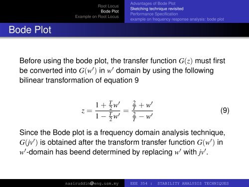
Before using the bode plot, the transfer function G(z) must first<br />
be converted into G(w ′ ) in w ′ domain by using the following<br />
bilinear transformation of equation 9<br />
z = 1 + T 2 w′<br />
1 − T 2 w′ =<br />
2<br />
T + w′<br />
2<br />
T − w′ (9)<br />
Since the Bode plot is a frequency domain analysis technique,<br />
G(jv ′ ) is obtained after the transform transfer function G(w ′ ) in<br />
w ′ -domain has beend determined by replacing w ′ with jv ′ .<br />
nasiruddin@eng.usm.my EEE 354 : STABILITY ANALYSIS TECHNIQUES