Symmetric Tripod - Rescue Consulting Canada
Symmetric Tripod - Rescue Consulting Canada
Symmetric Tripod - Rescue Consulting Canada

You also want an ePaper? Increase the reach of your titles
YUMPU automatically turns print PDFs into web optimized ePapers that Google loves.
!!!!Warning!!!<br />
You Must Thoroughly Read and Understand all instructions provided<br />
in this manual before use.<br />
You could be killed or seriously injured if you do not read and<br />
understand the user information before using this piece of<br />
equipment.<br />
Special Training and knowledge are required to use this equipment.<br />
Use and inspect this equipment only in accordance with these<br />
instructions.<br />
!!!!Warning!!!
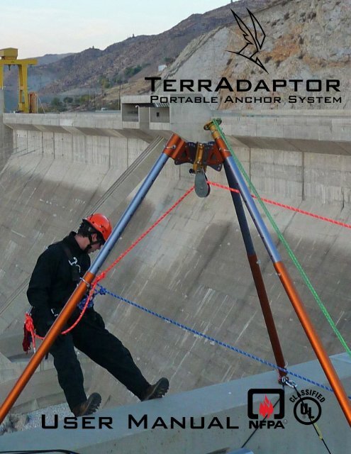
Portable Anchor System<br />
(Patent Pending)<br />
Table of Contents<br />
1. Introduction<br />
Product Overview 1<br />
Component Overview 3<br />
Testing and Warnings 4<br />
NFPA Users Information 6<br />
2. Assembly Instructions<br />
Leg Connections 8<br />
Height Adjustment-Leg assembly configurations 8<br />
Head Angle Adjustments 9<br />
Leg Clamps 11<br />
Feet 12<br />
Leg Hobble 13<br />
Main Attachment Point/Pins 14<br />
Auxiliary Attachment Points 16<br />
Head Assembly-<strong>Tripod</strong>, Quadpod, A-Frame 16<br />
Lash Ring 17<br />
Final Assembly – How to put it all together 18<br />
3. Configurations<br />
<strong>Symmetric</strong> <strong>Tripod</strong> 19<br />
<strong>Symmetric</strong> Quadpod 22<br />
Edge-A <strong>Tripod</strong> 23<br />
A Frame/Bi-pod 24<br />
Gin Pole/ Monopod 25<br />
Horizontal Span 26<br />
Field Use Charts 27<br />
Inspection & Maintenance Log 28<br />
4. Warranty and Replacement Parts 29-30
Section 1<br />
Introduction<br />
Product Overview<br />
Congratulations on your purchase of the TerrAdaptor Portable Anchor System.<br />
The TerrAdaptor is the most versatile portable anchor system available for use in<br />
rescue, industrial, and wilderness environments. This innovate high directional<br />
system is the result of the combined years of experience in the design, use and<br />
manufacturing of equipment by Pigeon Mountain Industries (PMI), Skedco, and<br />
Seattle Manufacturing Corporation (SMC).<br />
The TerrAdaptor system is unique in that it configures as a gin pole/monopod, an<br />
A-Frame/Bipod, a Quadpod and, of course, the most adjustable <strong>Tripod</strong> in the<br />
market today. Due to the extreme adjustability of the TerrAdaptor, countless<br />
non-standard configurations are available utilizing shallow angles and horizontals<br />
that are not available with other tripod systems in the market. With<br />
independently variable head angles and interchangeable components, the<br />
TerrAdaptor will adjust to your rescue environment whether it is rural, urban,<br />
industrial, or confined space.<br />
Layout of this Manual<br />
This manual is designed to aid in the assembly and configuration of the<br />
TerrAdaptor Portable Anchor System. It is not designed to provide the user with<br />
the theory and practice of using portable anchor systems, as this comes only<br />
from extensive training from qualified trainers on such systems. Do not attempt<br />
to use the TerrAdaptor without this specialized training as you could be<br />
killed or seriously injured.<br />
Section 2, Assembly Instruction, includes a detailed description of each of the<br />
major components of the TerrAdaptor System. This section explains how the<br />
individual pieces are used as well as how they are assembled together. Within<br />
each component description there is a “best practice” element, care and<br />
maintenance, as well as specific warnings for that element. Please refer to this<br />
section during routine inspection of the TerrAdaptor system as well as during<br />
your initial assembly process.<br />
Section 3, Configurations, includes information regarding various standard<br />
configurations the TerrAdaptor system has been designed for. This section<br />
summarizes the various settings needed to achieve the configuration as well as<br />
the breaking strength achieved for the configuration. The NFPA and ASTM<br />
standard achieved at each configuration is also indicated, if applicable.<br />
Section 4, Warranty and Replacement Parts, describes the warranty policy on<br />
your TerrAdaptor System and component parts. In addition, this section provides<br />
the listing of the component parts and their part numbers included in each kit<br />
TerrAdaptor Users Manual (Dec 2008) 1
available for purchase. Please refer to this section upon receiving your kit to<br />
assure all of your parts are properly included in the kits, as well as for a list of<br />
replacement parts that are available from your dealer.<br />
The TerrAdaptor System<br />
Multiple configurations of the TerrAdaptor Portable Anchor System can be built<br />
from various standard system components. The primary system revolves around<br />
the TerrAdaptor <strong>Tripod</strong> System (Part number NFPA230100). This system<br />
includes all of the necessary parts to assemble a standard symmetric tripod that<br />
provides the ability to reach a height of approximately10-feet. The system comes<br />
packaged in three compact packable bags to make it easy to “grab your bags<br />
and go” as well as store the System together in an organized manner. The<br />
individual component pieces included in the TerrAdaptor <strong>Tripod</strong> System are listed<br />
in Section 4 of this manual.<br />
To transition your <strong>Tripod</strong> to a Quadpod System, you can purchase the<br />
TerrAdaptor Quadpod Attachment Kit (Part Number 230105). This kit provides<br />
the fourth leg and attachment pieces necessary to transition your tripod into a<br />
quadpod. The individual component pieces included in the TerrAdaptor Quadpod<br />
are listed in Section 4 of this manual.<br />
If your needs are fairly simple and a single gin pole is the best solution for your<br />
situation, you can purchase the TerrAdaptor Gin Pole Kit (Part number 230106).<br />
This kit includes a full leg kit to reach approximately 10 feet in height adjustability.<br />
The individual component pieces for this kit are listed in Section 4.<br />
For those who typically encounter environments that require more than 10 feet of<br />
height, additional leg extension pieces (appropriately 4 feet in length) can be<br />
individually purchased for this use. This piece can also be used to provide one<br />
extra long leg if a tall “lazy leg” configuration is desired.<br />
Other replacement parts and options are available for the TerrAdaptor system<br />
and are listed in Section 4 of this manual.<br />
TerrAdaptor Users Manual (Dec 2008) 2
Major component Overview<br />
The images below are an overview of a tripod set-up.<br />
An overview of the head section along with the correct names of each component is<br />
presented below. Please refer to this image while learning how to assemble the<br />
TerrAdaptor as outline in Section 2.<br />
TerrAdaptor Users Manual (Dec 2008) 3
Testing Applied to the TerrAdaptor<br />
The TerrAdaptor system has been tested extensively in both lab and field<br />
environments. As a result, the TerrAdaptor Portable Anchor system in the<br />
standard symmetric tripod and quadpod configurations are the only systems of<br />
their kind to be certified by UL to NFPA 1983 (2006 ed.) Other useful<br />
configurations were also tested and have been included in this manual (Section<br />
3) for reference purposes.<br />
Each rescue situation is unique and the ultimate safety of the TerrAdaptor<br />
system rests in the knowledge and training of those setting up the system.<br />
Warnings<br />
Technical work and rescue, mountaineering and other rope assess<br />
activities are inherently dangerous. Any person or team using a<br />
portable anchor system must obtain qualified instruction prior to using<br />
such equipment in any manner. If you are not extremely versed in the<br />
understanding of resultant forces, high directional concepts and other<br />
basic issues regarding portable anchor systems theory, you are not<br />
qualified to use this device until adequately trained. Any person or team<br />
using the TerrAdaptor Portable Anchor System is responsible for their<br />
own decisions and actions. Failure to heed this warning can cause<br />
serious Injury or Death.<br />
Breaking Strengths listed in the configuration section are the maximum load<br />
sustained prior to system collapse. During testing, the typical system failure<br />
mode was the failure to sustain a load. This was due primarily to flexing and<br />
yielding of components, rather than the components themselves fracturing and<br />
releasing the load, as is typical in other rescue systems.<br />
Bent or warped components are the symptom of a system that has been<br />
overloaded. Continuing to use bent or warped components will unpredictably<br />
alter the system strength, possibly resulting in injury or death. If bent or distorted<br />
components of any kind are discovered, immediately discontinue use of the<br />
TerrAdaptor system until components are replaced, a safety analysis of the<br />
system has been performed, and corrective action implemented.<br />
Hardware item such as nuts, bolts, pins, etc, are specified by the manufacturer<br />
for strength and other characteristics which make them suitable for use in the<br />
TerrAdaptor system. Substituting with commonly available hardware store items<br />
may result in injury or death.<br />
As mentioned above, the breaking strengths presented represent the load<br />
prior to system collapse, not the working load of the system. The user is<br />
responsible for determining the proper working load required given the<br />
specific situation and the safety margins required to provide a safe<br />
environment for the circumstance.<br />
TerrAdaptor Users Manual (Dec 2008) 4
Please see our website www.TerrAdaptor.com for a listing of trainers that have<br />
extensive training experience with portable anchor systems. These trainers have<br />
experience with the TerrAdaptor.<br />
• YOU COULD BE KILLED OR SERIOUSLY INJURED IF YOU DO NOT<br />
READ AND UNDERSTAND THE USER INFORMATION BEFORE<br />
USING THIS PIECE OF EQUIPMENT<br />
• SPECIAL TRAINING AND KNOWLEDGE ARE REQUIRED TO USE<br />
THIS EQUIPMENT<br />
• YOU MUST THOROUGHLY READ AND UNDERSTAND ALL<br />
MANUFACTURER’S INSTRUCTIONS BEFORE USE<br />
TerrAdaptor Users Manual (Dec 2008) 5
Model NFPA230100<br />
TerrAdaptor Portable Anchor System<br />
Manufactured by Seattle Manufacturing Corporation (SMC)<br />
Made in USA<br />
USER INFORMATION<br />
CLASSIFIED BY UNDERWRITERS LABORATORIES EMERGENCY SERVICES<br />
AUXILIARY EQUIPMENT IN ACCORDANCE WITH THE NATIONAL FIRE<br />
PROTECTION ASSOCIATION STANDARD ON LIFE SAFETY ROPE AND<br />
EQUIPMENT FOR EMERGENCY SERVICES NFPA 1983 (2006 edition)<br />
20JF<br />
THIS PORTABLE ANCHOR SYSTEM MEETS THE AUXILIARY EQUIPMENT<br />
REQUIREMENTS OF NFPA 1983, STANDARD ON<br />
LIFE SAFETY ROPE AND EQUIPMENT FOR EMERGENCY SERVICES, 2006<br />
EDITION. MINIMUM BREAKING STRENGTH AND RATING ARE DETERMINED<br />
AT THE CONFIGURATION OF LOWEST STRENGTH PER MANUFACTURER’S<br />
INSTRUCTIONS<br />
The TerrAdaptor Portable Anchor System is G Rated in the standard configuration<br />
for the <strong>Tripod</strong> and Quadpod configuration at a height of 9 feet or less with an MBS of<br />
36kN.<br />
BEFORE USE<br />
The techniques employed in the proper and safe use of this equipment may only be<br />
learned through PERSONAL instruction received from an instructor who is well<br />
qualified in all phases of vertical rope work. Such instruction will include an<br />
evaluation of your comprehension of, and ability to perform, the tasks required to<br />
safely and efficiently use this equipment. Never attempt its use until you have<br />
received such instruction and are believed competent by your instructor. In addition,<br />
read and understand the attached user instruction manual.<br />
INSPECTION FOR USE<br />
Visually and by touch, inspect each of the component parts of the TerrAdaptor<br />
Portable Anchor System for cracks, distortion, corrosion, scratches or gouges,<br />
sharp edges or rough areas. Compare these parts with new ones if necessary to<br />
determine their condition. Review the assembly instruction manual section for detail<br />
descriptions of items to inspect. Remove each part from service if there is any doubt<br />
about its safety or serviceability<br />
SET UP FOR USE<br />
The TerrAdaptor Portable Anchor System is a very versatile piece of equipment.<br />
The versatility and the shear number of components in the system make this an<br />
extremely complex set-up for proper and safe function. User must get professional<br />
instruction as well as read and understand the attached user instructional manual.<br />
MAINTENANCE AFTER USE<br />
Carefully clean and dry all component parts of this device to remove all dirt or foreign<br />
material and moisture. Minor sharp edges may be smoothed with a fine abrasive<br />
cloth, before cleaning. Store in a clean, dry place.<br />
TerrAdaptor Users Manual (Dec 2008) 6
REMOVAL FROM SERVICE<br />
This TerrAdaptor Portable Anchor System and/or a component piece should be<br />
removed from service if distortion of any part is apparent, if any cracks are apparent,<br />
if exposed to heat sufficient to alter its surface appearance or if it has scratches or<br />
gouges of more than a superficial nature. Review the assembly instruction manual<br />
for detail descriptions of potential problems with component parts.<br />
ADDITIONAL INFORMATION<br />
Additional information regarding this type of equipment can be found in the following<br />
publications:<br />
NFPA 1500, Standard on Fire Department Occupational Safety and Health Program<br />
NFPA 1983, Standard on Life Safety Rope and Equipment for Emergency Services<br />
RECORDS<br />
It is suggested that the user of this portable anchor system keep a permanent record<br />
listing the date and results of each usage inspection. Such record should show, as a<br />
minimum, inspection for all of the following conditions for each component of the<br />
system. Refer to the user manual for explanation detail for each component piece:<br />
• Cleanliness<br />
• Dryness<br />
• Corrosion<br />
• Distortion<br />
• Excessive wear<br />
• Scratches<br />
• Gouges<br />
• Sharp edges<br />
• Presence of User Information sheet and User Instruction Manual.<br />
USE OF THIS USER INFORMATION SHEET<br />
It is suggested that this User Information sheet be retained in a permanent record<br />
after it is separated from the TerrAdaptor Portable Anchor System and that a copy of<br />
it be kept with the device. It is suggested that the user refer to this User Instructions<br />
before and after each use of this device.<br />
• YOU COULD BE KILLED OR SERIOUSLY INJURED IF YOU DO NOT<br />
READ AND UNDERSTAND THE USER INFORMATION BEFORE<br />
USING THIS PIECE OF EQUIPMENT<br />
• SPECIAL TRAINING AND KNOWLEDGE ARE REQUIRED TO USE<br />
THIS EQUIPMENT<br />
• YOU MUST THOROUGHLY READ AND UNDERSTAND ALL<br />
MANUFACTURER’S INSTRUCTIONS BEFORE USE<br />
• USE AND INSPECT THIS EQUIPMENT ONLY IN ACCORDANCE WITH<br />
THESE INSTRUCTIONS<br />
Manufactured by<br />
SEATTLE MANUFACTURING CORPORATION<br />
6930 SALASHAN PARKWAY- FERNDALE, WA. 98248 (800) 426-6251<br />
WWW.SMCGEAR.NET<br />
This sheet has been prepared in accordance with the requirements of NFPA<br />
TerrAdaptor Users Manual (Dec 2008) 7
Section 2<br />
Assembly instructions<br />
The TerrAdaptor is the most versatile and configurable portable anchor system<br />
on the market. This section will provide detailed information about each<br />
component in the system and how these components are assembled with one<br />
another. See Section 3 for instructions on setting up various configurations.<br />
Leg Tube Connections<br />
The height of the TerrAdaptor is easily adjusted by means of<br />
telescoping leg sections. Adjustment holes in small diameter leg<br />
sections (referred to as Perf Tubes) are labeled 1 through 9 and<br />
adjustment holes for the larger diameter mid section tubes (Mid<br />
Tubes) are labeled X and Y (fig1). Configuration charts assume legs<br />
are oriented with 1 at the bottom and 9 at top. A setting of X7 would<br />
indicate that the pin is to be used at the mid tube X hole and go<br />
through hole 7 on the perf tube. (Please note that the 7 will be<br />
covered up by the mid tube in this process).<br />
Fig 1 Leg Markings<br />
Leg connections and connections to various<br />
accessories are made by sliding the small<br />
diameter perf tube into the large diameter mid<br />
tube or other components and securing the<br />
connection with a Leg Coupling Pin. Leg<br />
coupling pins provide a secure connection<br />
when the pin is fully inserted and the bail is<br />
properly secured (fig 2).<br />
Fig 2 Properly<br />
Secured Leg Coupling<br />
Pin<br />
Fig 3 Improperly<br />
Secured Leg Coupling<br />
Pin<br />
Height Adjustability – Leg Assembly Configurations<br />
The TerrAdaptor can be used with as few as one leg section and is extendable<br />
up to a total of 4 sections per leg. The shortest leg configuration consists of just<br />
one perf tube attached to the head. Longer legs are assembled by alternating<br />
mid and perf tubes to reach the desired height as follows:<br />
1. The perf tube is the initial starting point (this tube section will always be<br />
used to attach to the head)<br />
2. Position and connect any lash rings where they might be needed<br />
3. Orient and attach leg clamps, either offset or centered<br />
4. Attach a mid tube as close to the leg clamp as possible. This connection<br />
is referred to as the Upper Leg Coupling in configuration charts<br />
5. A second perf tube can be added by connecting it to the bottom of the mid<br />
tube at whatever setting achieves your desired leg length. This<br />
TerrAdaptor Users Manual (Dec 2008) 8
connection is referred to as the Lower Leg Coupling in configuration<br />
charts<br />
6. For maximum length legs, an optional mid tube section (the 4 th section)<br />
can be connected to the bottom of the perf tube. This connection is<br />
referred to as the Optional Leg Coupling in configuration charts<br />
7. Any variety of foot options can be attached to the last leg section<br />
8. No additional sections can be attached beyond the four mentioned above<br />
Best Practice:<br />
When raising the height of a tripod, fully extend the lower leg section before<br />
extending the upper leg section. The legs are strongest when the most amount<br />
of tube overlap is near the head section. All configurations used should follow<br />
this practice.<br />
Care & Maintenance:<br />
File small dents and burrs from surface of leg sections. Clean parts with a water<br />
rinse and wipe dry. Clean parts last longer and assemble easier.<br />
Legs can be bent under severe loading. Retire leg sections that won’t fully slide<br />
into or over another leg section. Due to the potential causes of bent legs, they<br />
are not automatically replaceable. See the warranty section to determine the<br />
process of replacing bent legs.<br />
Leg coupling pins (Part number 230301) should be replaced when worn or bent.<br />
Warnings:<br />
• Do not tie into the leg coupling pin bail for any reason and avoid snagging<br />
with ropes and other rigging<br />
• Do not substitute leg coupling pins (or other hardware) with “like-kind” from<br />
your local hardware store as they may not meet the necessary strength<br />
requirements. Replacement leg coupling pins can be purchased from your<br />
dealer.<br />
Head Angle Adjustments<br />
Entirely unique to the TerrAdaptor is the<br />
ability to adjust the head angle in multiple<br />
directions. This allows the head to remain<br />
level even when the terrain is not. A level<br />
head means that rigging attached is<br />
clean, safe, and organized.<br />
The main head and the half plate each<br />
have 10 oval shaped holes on the outside<br />
curve which serve as adjustment holes.<br />
The inner 6 holes are marked A through F<br />
for angle reference purposes. Head angle<br />
Fig 4<br />
Load Locking Head Pins<br />
(Parked position)<br />
adjustments are achieved by pivoting leg clamps to desired angles A through F<br />
and locking in place by using three Load Locking Head Pins.<br />
TerrAdaptor Users Manual (Dec 2008) 9
Fig 5 Detent Pin used to “lock” the<br />
Load Locking Pin in place.<br />
Insert this way<br />
The Load locking head pins are designed to<br />
“lock” in place with the inclusion of a detent pin<br />
(fig 5) inserted into the leg clamp. Please note<br />
that the detent pin is only included on one side<br />
of each of the leg clamp assembly. The load<br />
locking pin must be inserted from the side<br />
which includes the detent pin. The load locking<br />
head pin can be locked in either the “parked”<br />
position as shown in figure 4 or the fully<br />
inserted position as shown in figure 6.<br />
As the load locking head pins are designed<br />
to resist movement under loads, the head<br />
must be unloaded to adjust the leg angle.<br />
To adjust the angle, pull the two outer pins<br />
to the parked position, leaving the inner pin<br />
for the leg to pivot on (as configured in fig<br />
4). Adjust to the desired or recommended<br />
angle and return the 2 parked pins to their<br />
fully installed positions (fig 6). Cotter pins<br />
are supplied for the load locking head pin if<br />
additional security is desired or if the pins<br />
could be subjected to inadvertent force<br />
which may push them out of position.<br />
Fig 6 Fully inserted pins properly<br />
protruding from leg clamp<br />
Best Practice:<br />
Head angle adjustments are easiest to make when the TerrAdaptor is unloaded<br />
and laying flat on ground prior to final installation. Use Configuration Tables in<br />
section 3 for recommended angles.<br />
Care & Maintenance:<br />
Clean parts with water rinse and wipe dry. Clean parts last longer and adjust<br />
easier.<br />
Check for excessive wear on the load locking head pin as indicated by wearing<br />
through of the hardcoat anodizing. Load locking head pins can be re-ordered as<br />
replacement parts (Part number 230260) when worn or lost.<br />
Warnings:<br />
• Do not use the device if the load locking head pins cannot be fully inserted.<br />
This may be an indication that the device is not properly configured or<br />
excessive loads have caused some distortion beyond safe use<br />
• Check configuration tables for proper and safe angles (see section 3)<br />
• Retire load locking head pins when wear through of the hardcoat anodizing is<br />
evident<br />
TerrAdaptor Users Manual (Dec 2008) 10
Leg Clamps<br />
Leg Clamps are the means of attaching leg sections to the main head of the<br />
TerrAdaptor. Two types of clamps, Centered and Offset, are used in the tripod<br />
configuration.<br />
Although the different style leg clamps are safe to use in<br />
any position, the centered clamp is most commonly used<br />
on the rear leg (fig 8), while the offset clamps are used in<br />
the side legs. For the typical tripod setup the offset clamps<br />
Fig 8 Rear leg with<br />
centered leg clamp. Legs<br />
are able to by-pass each<br />
other due to offset leg<br />
clamp orientation<br />
Fig 7 Offset Leg Clamps (left-facing forward; right-facing backwards)<br />
for illustrative purposes. Best practices has both offset leg clamps facing<br />
forward in a typical tripod configuration set up<br />
are oriented with the offset leg tubes facing forward (away from the rear leg)<br />
providing the most stable and symmetric configuration.<br />
In some setups, for space or rigging considerations, it may be desirable for both<br />
side legs to extend through the head. In this case, set one side leg clamp facing<br />
forward and the other backwards so that leg tubes may bypass each other<br />
without interference (fig 8). This alternating forward and backward leg clamp<br />
arrangement is also ideal for rigging sideways A-Frames with greater stability<br />
and a greater working area under the head.<br />
The perf leg tubes slide through the leg clamps and are secured in position by<br />
using the leg coupling pin. Leg clamps are attached to the head by means of 3<br />
load locking head pins as shown in figure 6.<br />
Best Practice:<br />
Use centered leg clamp on the rear leg and set both offset leg clamps facing<br />
forward when configuring as a standard tripod.<br />
For symmetric or edge-A tripods use centered leg clamp on the rear leg and set<br />
both offset leg clamps facing forward on the side legs.<br />
For sideways A-frames use alternating forward and backward facing leg clamps.<br />
TerrAdaptor Users Manual (Dec 2008) 11
Care & Maintenance:<br />
Clean parts with water rinse and wipe dry. Clean parts last longer and assemble<br />
easier. Check for excessive wear of load locking head pin.<br />
Check leg clamps for warping. If leg clamps have been warped, the entire<br />
system may be at risk. Refer to warranty section for information on replacing the<br />
leg clamps.<br />
Warnings:<br />
• Do not use device if any of the load locking head pins cannot be fully inserted<br />
• Check configurations tables for proper and safe angles to be used<br />
• Retire pins when worn or bent<br />
• Do not use the system if leg clamps are warped or damaged such that they<br />
do not move freely with mating parts<br />
Feet<br />
The TerrAdaptor comes standard with<br />
aluminum half round Ball Feet that are<br />
suitable for most leg angles and<br />
surfaces from hardpack dirt to most<br />
industrial surfaces. Wide leg angles<br />
and slick surfaces are a dangerous<br />
combination and in this situation the<br />
standard ball foot can be rotated so<br />
that its hardened steel spike will bite<br />
into the surface (fig 9).<br />
Fig 9 Ball Foot with hobble ring, basket and quick link<br />
(left –spike rotated into ground, right – round surface<br />
on ground)<br />
The standard ball feet are designed to accept a ring for attaching leg hobbles and<br />
Baskets whose large surfaces resist penetration of the legs into snow, sand,<br />
mud and other soft surfaces.<br />
The optional Articulating Foot Assembly (Part number 230400)<br />
is available for the TerrAdaptor. Articulating feet swivel on a<br />
stainless ball and have a rubber pad for use on hard surfaces<br />
such as concrete or other flooring surfaces. Additionally, there are<br />
holes for attaching the foot by means of screws, bolts, or driven<br />
spikes. Three large holes are also available for clipping and<br />
lashing the foot to other objects. For extreme wide leg angles or<br />
other special circumstances the articulating foot can rotate 90<br />
degrees to the flat position.<br />
Fig 10 Articulating<br />
Foot with Hobble Plate<br />
and Quick link<br />
All feet are easily attached to either the large or small diameter leg tubes by<br />
means of a leg coupling pin. Generous clearances between the feet and leg<br />
tubes allow mud, rocks and debris to not interfere with foot attachment.<br />
TerrAdaptor Users Manual (Dec 2008) 12
Best Practice:<br />
Select the feet option (use of ball foot, spike or optional articulating foot) and feet<br />
position before setting up tripod. Feet are not easily exchanged when the<br />
TerrAdaptor is loaded or hobble is tight.<br />
Care & Maintenance:<br />
Standard ball foot, articulating foot, hobble plate and quick link can be cleaned<br />
with a water rinse and simple wipe dry.<br />
On all types of feet, check for bent or loose components before use. Ball foot<br />
replacement kits are available (Part number 230217) when retirement is needed.<br />
If the spike becomes dull and rounded from use, the point can be lightly filed with<br />
a common file until sharpened.<br />
Warnings:<br />
• Using the TerrAdaptor without feet is not advisable. Contact of leg ends on<br />
hard surfaces will permanently damage the legs<br />
• Carabiners clipped into articulating feet should be properly positioned to avoid<br />
cross or side loading of the carabiners<br />
• Do not clip into the basket<br />
Leg Hobble<br />
Leg Hobbles are an important structural element for the<br />
TerrAdaptor. It is important to understand that the ultimate<br />
strength of any configuration depends on the ability to<br />
secure the feet against movement by either hobbling the<br />
legs together or direct attachment of the feet (or legs)<br />
through bolts, lashing, or other means of eliminating the<br />
possibility of movement of the legs.<br />
The Rope Hobble provided with each TerrAdaptor is light,<br />
versatile, and much easier to use than a standard chain<br />
hobble. The rope and prussic cord used in the hobble is<br />
specially designed for low stretch and high strength. (If<br />
chain is used, the chain is attached to the hobble plate in a<br />
similar manner as the rope hobble (fig 11)).<br />
Fig 11<br />
Rope Hobble attachment by<br />
Quick Link<br />
After positioning and adjusting other<br />
elements of the TerrAdaptor, attach<br />
the rope hobble with a quick link on<br />
each rotating Hobble Ring. When<br />
attaching the rope hobble, clip the<br />
small sewn loop into the quick link<br />
on one foot. Slip the prussic to<br />
create a large loop of rope as seen<br />
in figure 12 and attach this loop to<br />
the quick link at the foot of the<br />
second leg. Grasp prussic and pull<br />
Fig 12 Rope Hobble Loop with Prussic. Sewn loop connected to quick<br />
link; large loop connected to 2 nd leg quick link.<br />
TerrAdaptor Users Manual (Dec 2008) 13
on tail of rope to take most of the slack out of loop. Repeat this with all three of<br />
the rope hobbles and fully close the quick links. To do final adjustments, tighten<br />
the rope hobble, one at a time, until each leg flexes in slightly, or in the case of<br />
an NFPA configuration, until the correct hobble length is reached. Tables<br />
included in Section 3 of this manual include the ideal hobble adjustment for the<br />
various configurations.<br />
Best Practice:<br />
Adjust the head angle, leg length and leg heights before the hobble is attached<br />
and tightened. Even a lightly tightened hobble can make other adjustments<br />
difficult to accomplish.<br />
Care & Maintenance:<br />
Check the rope hobble for cuts and worn areas and replace as necessary (Part<br />
number 230307).<br />
Check the prussics for proper operation.<br />
Make sure quick links are able to close completely and are free from burrs and<br />
sharp edges that may harm rope. File or sand if needed.<br />
Check lashing holes in articulating feet for sharp edges or burrs and file or sand<br />
to remove as needed.<br />
Warnings:<br />
• Do not use the TerrAdaptor without feet hobbled, lashed or somehow secured<br />
into position<br />
• Rope hobbles may deteriorate with prolonged exposure to the elements<br />
• Sharp edges may cut ropes and webbing. Do not tie directly into holes and<br />
quick links which have sharp edges<br />
• Use chain rather than rope when hobbling in an environment where<br />
chemicals are present that may damage or harm the rope<br />
Main attachment point<br />
The main load bearing attachment point on the TerrAdaptor is a<br />
two position yoke located at the bottom of the main head. Items<br />
are attached to the head with the use of the Main Attachment<br />
Pin, which is a quick release ball lock pin (fig 13). Insert the main<br />
attachment pin into the yoke while holding the release button in.<br />
Once the main attachment pin is in place, the release button will<br />
“pop” back out (fig 15) and the ball lock detent pins will engage<br />
and prevent the pin from being pulled back through the yoke.<br />
Fig 13 Main<br />
Attachment Yoke<br />
• The narrow portion of the yoke is designed for an auxiliary<br />
sheave but is also suitable for a rescue carabiner or other<br />
gear (fig 14).<br />
• The wide portion of the yoke is designed for bulky gear<br />
Figure 14<br />
TerrAdaptor Users Manual (Dec 2008) 14
such as swivels or multi-sheave pulleys, but again, is suitable for all types<br />
of rescue gear. The wide yoke is also preferred for use with pulleys when<br />
shifting loads may side load a pulley restricted by the narrow yoke (fig 14).<br />
Best Practice:<br />
When changing out gear there is no need to fully remove the main attachment<br />
pin from the yoke as it can be temporarily parked in the last attachment hole.<br />
This facilitates the ease of using both hands to maneuver the gear into the yoke<br />
and then sliding the pin back through the entire yoke area.<br />
Fig 15 Release Button<br />
Fig 16 Left pin – retired due to wear<br />
and detent pins not properly working;<br />
Right pin – in good working condition<br />
Care & Maintenance:<br />
Clean parts with water rinse and wipe dry. Clean parts last longer and assemble<br />
easier.<br />
Check that release button moves freely (fig 15) and that locking detent pins move<br />
in and out with release button (fig 16).<br />
Check proper pin engagement in yoke by attempting to pull the main attachment<br />
pin out of the yoke without depressing the release button; if removable without<br />
depressing button, do not use and retire pin immediately (Part number 230311)<br />
Check that pin is not bent or dented by installing pin into yoke; it should move<br />
freely in and out when release button is depressed.<br />
Warnings:<br />
• Do not run a moving rope directly over the main attachment pin. This may<br />
cause excessive wear on the pin and/or cause the pin to roll and potentially<br />
cause wear damage in the yoke attachment holes<br />
• Retire main attachment pin if button or ball detents do not return to “popped”<br />
out position once released<br />
• Do not use load attachment pin that is bent or does not function properly<br />
TerrAdaptor Users Manual (Dec 2008) 15
Auxiliary Attachment Points<br />
There are three Auxiliary<br />
Attachment Points on a<br />
tripod head that are suitable<br />
for clipping carabiners and<br />
other rigging gear into (fig 17).<br />
Do not clip into the head angle<br />
adjustment holes as these are<br />
not designed as load bearing<br />
connection points.<br />
Fig 17 Head Auxiliary attachment points<br />
Care & Maintenance:<br />
Clean parts with water rinse and wipe dry. Clean parts last longer and assemble<br />
easier.<br />
Warnings:<br />
• Do not clip into head angle adjustment holes<br />
Head Assembly – <strong>Tripod</strong>, Quadpod, A-Frame/Bi-Pod<br />
The TerrAdaptor <strong>Tripod</strong> head consists of a Main<br />
Plate with a single attached Half Plate. A Quadpod<br />
head consists of a main plate with two half plates.<br />
Half plates can remain attached to the main plate<br />
even if they are not used in the configuration.<br />
Half plates are attached to the main plate with the<br />
Yoke facing down. Attach the half plate to the main<br />
plate with 4 socket head bolts (1-1/4” long for tripod<br />
configuration and 1-3/4” long for a quadpod<br />
configuration). To remove half plates, loosen and<br />
remove all 4 bolts, then separate half plates from<br />
main plate.<br />
Fig 18<br />
Half Plate attachment<br />
to Main Plate<br />
To attach half plates, clean all parts (including nuts and bolts) then select bolts<br />
(long for quadpod or short for tripod) and insert all 4 bolts and hand tighten into<br />
nylon locking nuts. Then tighten all 4 bolts to 450 in/lbs and check that assembly<br />
is tightly mated and that the bolt protrudes beyond flush on all four bolts.<br />
TerrAdaptor Users Manual (Dec 2008) 16
Fig 19 Bolt protrudes<br />
just beyond flush<br />
Best Practice:<br />
Leaving the half plate on while using as an A-Frame<br />
allows for quicker setup times and more available lash<br />
and load points.<br />
Care & Maintenance:<br />
Check attachment holes for sharp edges and burrs.<br />
File or sand to remove sharp edges.<br />
Check main and half plates for bends and/or warping.<br />
This could indicate over loading of the head. See the warranty section for the<br />
replacement policy on these component parts.<br />
Check to make sure all 4 bolts are tight before each use. Any small gap between<br />
the head plates and half plates may cause significant instability when the system<br />
is loaded.<br />
Fig 20 Do not remove<br />
these screws<br />
Warnings:<br />
• The three screws attaching the half plate to yoke<br />
plate as shown in figure 20 are not user serviceable. Do<br />
not remove<br />
• Do not lash or attach other gear to the array of holes<br />
intended for the load locking head pins. Damage in this<br />
area will disrupt normal adjustment of head angle (fig 17)<br />
• Do not substitute nuts or bolts (or other hardware)<br />
with “like-kind” from your local hardware store as they<br />
may not meet the necessary strength requirements.<br />
Replacement bolt kits can be purchased from your<br />
dealer (Part number 230326)<br />
Lash Ring<br />
The TerrAdaptor Lash Ring is designed to provide<br />
multiple attach points for stabilizing the tripod. Each<br />
TerrAdaptor tripod comes with 2 lash rings and additional<br />
accessory lash rings are available for purchase, if desired.<br />
Lash rings can be installed in any position, in any quantity<br />
and in any orientation along the perf tubes (small diameter<br />
leg). For lighter loads, especially in a MonoPod<br />
configuration, the lash ring may serve as an auxiliary main<br />
attachment point.<br />
Fig 21 Lash ring on tripod<br />
Best Practice:<br />
When a tieback could be subjected to a load over 5,000 lbs (22 kN), consider<br />
clipping directly into the stronger holes on the head plate rather than the lash<br />
ring.<br />
TerrAdaptor Users Manual (Dec 2008) 17
Care & Maintenance:<br />
Check for bending and warping which could<br />
indicate overloading.<br />
Because the lash ring is both tied into and<br />
clipped into, pay careful attention to sharp<br />
edges or burrs that may have developed.<br />
Lightly file or sand off burrs before use.<br />
Additional lash rings may be purchased<br />
(Part number 230230)<br />
Fig 22 Lash Ring<br />
used near foot<br />
section for<br />
increased stability<br />
Warning:<br />
• Carabiners clipped into lash rings should<br />
be positioned to avoid cross or side loading.<br />
Fig 23 Lash Ring<br />
atop of gin pole as<br />
main attachment<br />
Final Assembly – How to put it all together<br />
The fastest and safest way to set up any configuration of the TerrAdaptor system<br />
is to start with it lying on the ground, if possible. Each situation is different and<br />
users are responsible for ensuring their own safety while erecting and<br />
using this product. Erecting a typical <strong>Tripod</strong> configuration can be done by<br />
laying it out on the ground as follows:<br />
1. First set all legs to target height<br />
2. Attach leg clamps and feet to the<br />
legs<br />
3. Attach front legs to the main plate,<br />
setting leg angles at this time<br />
4. Still leaving the TerrAdaptor flat<br />
on the ground, attach the rear leg<br />
to the half plate pivot point, and<br />
lock in angle, if desired<br />
5. Rig safety ropes, lines or<br />
webbing; also installing rigging in<br />
the yoke at this time may be<br />
desirable especially when the<br />
yoke may be out of reach once<br />
Fig 24<br />
tripod is standing<br />
6. Raise the TerrAdaptor upright by<br />
lifting front legs and tilting towards the rear leg<br />
7. Recheck all connections before continuing to rig tripod<br />
8. Carefully and with all necessary safety measures, move unit into position<br />
before attaching hobbles or securing feet<br />
Final Assembly Steps<br />
TerrAdaptor Users Manual (Dec 2008) 18
Section 3<br />
Configurations and Set-up Tables<br />
Standard Configurations<br />
The TerrAdaptor is both very modular and highly adjustable, lending itself to an<br />
almost unimaginable number of configurations. We have identified and tested a<br />
core group of configurations that we feel addresses a broad range of rope rescue<br />
applications. By providing this information we hope that users will find<br />
configurations that fit their needs as well as provide a basis for developing new<br />
configurations. As with any piece of rope rescue gear, the user is ultimately<br />
responsible for ensuring that it meets their safety and performance<br />
requirements.<br />
The following section outlines the core group of configurations and provides the<br />
TerrAdaptor settings used to achieve the configurations. Each table includes the<br />
required setting for head angles, leg height adjustment references, and hobble<br />
lengths to achieve various heights. The table also identifies the manufacturers<br />
tested breaking strength of the system at the acquired height.<br />
The height indicated on the table is the height from the ground to the main<br />
attachment point and is expressed in feet. If there is “N/A” in the leg section, then<br />
the third or fourth leg is not needed to achieve the designated height. For<br />
example, to achieve the 5-foot height, only the first two legs are needed and they<br />
are joined at Y4. If a 7-foot height were desired three tubes would be required.<br />
Also note that the main plate head angle settings are expressed with 2 listings for<br />
both the left and right hand side of the head. In all of the examples listed below,<br />
the angles are the same on both sides of the head, but this may not always be<br />
the case in the field.<br />
I. <strong>Symmetric</strong> <strong>Tripod</strong> (includes NFPA<br />
configuration)<br />
<strong>Symmetric</strong> <strong>Tripod</strong>s are typically used for straight<br />
vertical access such as above manholes or<br />
access hatches. When straddling a manhole or<br />
access hatch, a symmetric tripod’s feet are equal<br />
distance from the center of the manhole or<br />
hatch. All three legs are equally loaded. This is<br />
most often the strongest tripod configuration.<br />
TerrAdaptor Users Manual (Dec 2008) 19
Table 1<br />
<strong>Symmetric</strong> <strong>Tripod</strong><br />
Height<br />
Upper<br />
Section<br />
Coupling<br />
Lower<br />
Section<br />
Coupling<br />
Main Plate Head Angle Settings - A/A<br />
Half Plate Head Angle Settings - B<br />
Optional<br />
Section Hobble Breaking<br />
Coupling Length Strength<br />
4 X7 n/a n/a 42” 12,200<br />
5 Y4 n/a n/a 54” 12,000<br />
6 X2 n/a n/a 60” 9,300<br />
7 Y7 X9 n/a 69” 12,100<br />
8 X5 X9 n/a 77” 9,400<br />
9 Y2 X9 n/a 78” 9,300<br />
Applicable<br />
Standards<br />
NFPA,<br />
ASTM<br />
NFPA,<br />
ASTM<br />
NFPA,<br />
ASTM<br />
NFPA,<br />
ASTM<br />
NFPA,<br />
ASTM<br />
NFPA,<br />
ASTM<br />
10 X1 X9 n/a 70” 7,800 ASTM<br />
11 X6 X9 X1 78” 8,200 ASTM<br />
12 Y3 X9 X1 78” 5,600 ASTM<br />
13 X1 X9 X1 78” 4,600<br />
How Head angles affect tripod strength<br />
There are many factors that go into the proper<br />
set-up and stability of a tripod system, which is<br />
why intensive personal training is required with<br />
the TerrAdaptor. Two of the main factors affecting<br />
the total strength and safety of a placement are the<br />
head angle used and the overall height of the<br />
system. As a guideline, for a given height, the wider<br />
the head angles the lower the strength. For example,<br />
the following table shows how a 7-foot tripod<br />
breaking strength declines from 12,100 lbf. to 7,700<br />
lbf. just by slightly increasing the head angle.<br />
TerrAdaptor Users Manual (Dec 2008) 20
Table 2<br />
<strong>Symmetric</strong> <strong>Tripod</strong><br />
setup angle<br />
comparison<br />
Height<br />
Main Plate Head<br />
Angle setting<br />
Half Plate Head<br />
Angle setting<br />
Upper<br />
Section<br />
Coupling<br />
Lower<br />
Section<br />
Coupling<br />
Hobble<br />
Length<br />
Breaking<br />
Strength<br />
7’ A/A B Y7 X9 Tight 12,100<br />
7’ B/B C<br />
7’ C/C D<br />
Front – X5<br />
Rear – Y6<br />
Front – Y2<br />
Rear – X6<br />
Front – X9<br />
Rear – X9<br />
Front – X9<br />
Rear – X9<br />
Applicable<br />
Standards<br />
NFPA,<br />
ASTM<br />
Tight 10,100 ASTM<br />
Tight 7,700 ASTM<br />
Wide <strong>Tripod</strong> Configurations<br />
In many cases a wide and more stable configuration is desirable even at the<br />
expense of breaking strength. Wide configurations also offer a larger work area<br />
under the tripod. The following table shows strength of a few wide stable<br />
configurations which have very large work areas.<br />
Table 3<br />
<strong>Symmetric</strong> <strong>Tripod</strong> –<br />
Wide setup<br />
Height<br />
Main Plate Head<br />
Angle setting<br />
Half Plate Head<br />
Angle setting<br />
7’ B/B C<br />
8’ B/B C<br />
8 ½’ B/B C<br />
Upper<br />
Section<br />
Coupling<br />
Front – X5<br />
Rear – Y6<br />
Front – Y2<br />
Rear – Y4<br />
Front – X1<br />
Rear – X3<br />
Upper<br />
Section<br />
Coupling<br />
Front – X9<br />
Rear – X9<br />
Front – X9<br />
Rear – X9<br />
Front – X9<br />
Rear – X9<br />
Hobble<br />
Length<br />
Breaking<br />
Strength<br />
Applicable<br />
Standards<br />
Tight 10,100 ASTM<br />
Tight 9,600 ASTM<br />
Tight 8,300 ASTM<br />
TerrAdaptor Users Manual (Dec 2008) 21
II. <strong>Symmetric</strong> Quadpod (includes<br />
NFPA configuration)<br />
<strong>Symmetric</strong> Quadpods fill the same role as<br />
symmetric tripods, but with added strength<br />
and stability of a fourth leg.<br />
Table 4<br />
<strong>Symmetric</strong> Quadpod<br />
Main Plate Head Angle Settings - A/A<br />
Half Plate Head Angle Settings - A/A<br />
Height<br />
Upper<br />
Section<br />
Coupling<br />
Lower<br />
Section<br />
Coupling<br />
Optional<br />
Section<br />
Coupling<br />
Hobble<br />
Length<br />
Breaking<br />
Strength<br />
4 Y7 n/a n/a 29” 13,000<br />
5 X5 n/a n/a 33” 12,100<br />
6 Y2 n/a n/a 36” 12,100<br />
7 Y7 X9 n/a 38” 12,200<br />
8 Y5 X9 n/a 40” 12,600<br />
9 Y3 X9 n/a 42” 11,500<br />
Applicable<br />
Standards<br />
NFPA,<br />
ASTM<br />
NFPA,<br />
ASTM<br />
NFPA,<br />
ASTM<br />
NFPA,<br />
ASTM<br />
NFPA,<br />
ASTM<br />
NFPA,<br />
ASTM<br />
10 X1 X9 n/a 46” 8,500 ASTM<br />
11 Y7 X9 X1 46” 8,100 ASTM<br />
12 Y4 X9 X1 46” 7,100 ASTM<br />
13 X1 X9 X1 46” 5,100 ASTM<br />
TerrAdaptor Users Manual (Dec 2008) 22
III. Edge-A <strong>Tripod</strong><br />
Probably the most popular configuration for an over the edge rescue, the Edge-A<br />
<strong>Tripod</strong> is essentially an A-Frame with the added stability of a third leg. Edge A<br />
configurations are popular for their large work areas, high strength and the ability<br />
to configure the A leaning either over or away from the edge. The TerrAdaptor’s<br />
rear leg can be left to hinge (unsecured) or can be pinned in place for added<br />
stability.<br />
Table 5<br />
Edge A <strong>Tripod</strong><br />
Main Plate Head Angle Settings - B/B<br />
Height<br />
Half Plate<br />
Head<br />
Angle<br />
6’ D<br />
7’ C<br />
Upper<br />
Section<br />
Coupling<br />
Front - Y7<br />
Rear – X1<br />
Front – X5<br />
Rear – X1<br />
Lower<br />
Section<br />
Coupling<br />
Front – X9<br />
Rear – X9<br />
Front – X9<br />
Rear – X9<br />
Hobble<br />
Length<br />
Front – 112”<br />
Side – 136”<br />
Front – 116”<br />
Side – 122”<br />
Breaking<br />
Strength<br />
Applicable<br />
Standards<br />
9,100 ASTM<br />
9,600 ASTM<br />
TerrAdaptor Users Manual (Dec 2008) 23
IV. A-Frame/Bi-Pod<br />
The TerrAdaptor is easily configured as a standard A-Frame or a Sideways A-<br />
Frame often used in narrow areas like catwalks. The half plate can be removed<br />
to eliminate weight and opportunities for it to be in the way, or it may remain<br />
attached.<br />
Table 6<br />
A-Frame<br />
Main Plate Head Angle Settings - B/B<br />
Hobble Breaking<br />
Height Upper Leg Lower Leg Length Strength Applicable Standards<br />
7’ X5 X9 120” 5,600 ASTM<br />
TerrAdaptor Users Manual (Dec 2008) 24
V. Gin Pole/Monopod<br />
The Gin Pole or Monopod is the TerrAdaptor’s lightest high anchor configuration.<br />
A properly rigged gin pole/monopod can support several thousand pounds while<br />
remaining a lightweight, single leg assembly. The Gin Pole is also ideal for close<br />
quarters where there is not enough room for multi-leg configurations.<br />
Table 7<br />
Monopod<br />
Hobble Breaking<br />
Height Upper Leg Lower Leg Length Strength<br />
8’ Y6 Y9 n/a 4,500<br />
Applicable Standards<br />
TerrAdaptor Users Manual (Dec 2008) 25
VI. Horizontal Span<br />
Unlike other tripods, the TerrAdaptor<br />
can be configured to span horizontal<br />
voids such as trenches, catwalks,<br />
pits or small streams. As shown in<br />
this figure a void can be spanned by<br />
using either 1 or 2-leg assembly<br />
depending on the span length and<br />
strength required.<br />
Warning<br />
The horizontal span can be one of the weakest configurations and should<br />
be used with great caution.<br />
Table 8<br />
Horizontal Beam<br />
Span Leg Tubes Breaking Strength<br />
4’ Single 5,600<br />
4’ Double 8,200<br />
6’ Single 3,500<br />
6’ Double 5,900<br />
8’ Double 4,000<br />
TerrAdaptor Users Manual (Dec 2008) 26
Field Use Charts<br />
The following blank charts are provided as a tool to document the settings that<br />
are used by your team. Consider copying and placing laminated sheets in your<br />
kit to aid in fast set-ups once you have established the ideal settings for your<br />
applications.<br />
<strong>Tripod</strong> Main Plate Head Angle Settings - /<br />
Half Plate Head Angle Settings - /<br />
Upper Lower Optional<br />
Section Section Section Hobble Notes<br />
Height coupling coupling Coupling Length<br />
Edge A <strong>Tripod</strong> Main Plate Head Angle Settings - /<br />
Height<br />
Half Plate<br />
Head<br />
Angle<br />
Upper<br />
Section<br />
coupling<br />
Front - __<br />
Rear - __<br />
Lower<br />
Section<br />
coupling<br />
Front - __<br />
Rear - __<br />
Hobble<br />
Length<br />
Front - __<br />
Rear - __<br />
Notes<br />
Front - __<br />
Rear - __<br />
Front - __<br />
Rear - __<br />
Front - __<br />
Rear - __<br />
A-Frame<br />
Height Upper Leg Lower Leg<br />
Main Plate Head Angle Settings - /<br />
Hobble<br />
Length<br />
Notes<br />
TerrAdaptor Users Manual (Dec 2008) 27
<strong>Symmetric</strong> Quadpod Main Plate Head Angle Settings - /<br />
Half Plate Head Angle Settings - /<br />
Height<br />
Upper<br />
Section<br />
coupling<br />
Lower<br />
Section<br />
coupling<br />
Optional<br />
Lower Leg<br />
Hobble<br />
Length<br />
Notes<br />
Inspection & Maintenance Log<br />
Date<br />
Inspector (routine<br />
maintenance completed by)<br />
Corrective Repairs and Maintenance<br />
performed, if any<br />
TerrAdaptor Users Manual (Dec 2008) 28
Section 4<br />
Warranty and Replacement Parts<br />
Warranty<br />
Standard SMC warranty policy applies to the TerrAdaptor System and its<br />
component parts:<br />
LIMITED WARRANTY: SMC products are warranted to the original purchaser in<br />
accordance with the full Statement of Limited Warranty printed on our web site,<br />
www.smcgear.net/warranty. Service under this warranty is available by contacting us by<br />
mail, email or phone. All items that are claimed to be defective must be returned under a<br />
pre-assigned CC Number and should include a detailed description of the conditions<br />
existing during use of the item as well as the place and date of the original purchase and<br />
a copy of the original invoice or receipt. Include contact information.<br />
Due to the complexity of the TerrAdaptor system, if one of the main components<br />
of the system has been damaged whereby it is warped, twisted, or bent, the<br />
entire system is suspect and must be inspected by the manufacturer. As a<br />
result, replacement parts for these components are not available without first<br />
sending them to SMC for inspection.<br />
If during inspection the parts are determined to be damaged as a result of a<br />
manufacturer defect, the necessary part(s) will be replaced at no cost to the end<br />
user. If the manufacturer determines that the damage is due to miss-use,<br />
overloaded, unsafe configurations or neglect, the replacement part(s) will be<br />
made available to the user at user’s cost. Any parts deemed unsafe will not be<br />
returned to the user.<br />
Replacement Parts and Kit components:<br />
NFPA230100<br />
TerrAdaptor <strong>Tripod</strong> System<br />
TerrAdaptor <strong>Tripod</strong> Head<br />
2 Offset Leg Clamps with 3 Load Locking Pins each<br />
Center Leg Clamp with 3 Load Locking Pins<br />
Main Attachment Pin<br />
3 Legs Kits complete with Feet, Hobble Plates & Baskets<br />
3 Rope Hobble Sections<br />
Cotter Pin Kit<br />
1 Extra Leg Coupling Pin and Load Locking Pin<br />
2 Lash Rings with 1 Coupling Pin each<br />
TerrAdaptor Head/ Accessory Bag<br />
2 TerrAdaptor Leg Bags<br />
TerrAdaptor User Guide<br />
TerrAdaptor Users Manual (Dec 2008) 29
230105 TerrAdaptor Quadpod Attachment Kit<br />
Quadpod Head Attachment<br />
Leg kit complete with Foot, Hobble Plate & Basket<br />
Center Leg Clamp with 3 Load Locking Pins each<br />
Main Attachment Pin<br />
Rope Hobble Section<br />
230106 TerrAdaptor Gin Pole Kit<br />
2 Lash Rings with 1 Coupling Pin each<br />
Leg kit complete with Foot, Hobble Plate & Basket<br />
TerrAdaptor User Guide<br />
230217 Foot Replacement Kit<br />
Ball Foot<br />
Hobble Plate with Quick Link<br />
Basket<br />
Leg Coupling Pin<br />
230230 Lash Ring Assembly<br />
1 Lash Ring<br />
1 Leg Coupling Pin<br />
230326 Bolt Replacement Kit<br />
4 SHCS Alloy Bolts<br />
4 Nylok Nuts<br />
230107 Leg Extension Kit<br />
1 Mid-Tube<br />
1 Leg Coupling Pin<br />
230260 Load Locking Head Pin<br />
230311 Main Attachment Pin<br />
230301 Leg Coupling Pin<br />
230307 Rope Hobble Section<br />
230314 TerrAdaptor Leg Bag<br />
230315 TerrAdaptor Head Bag<br />
230400 Articulating Foot<br />
TerrAdaptor Users Manual (Dec 2008) 30
SMC<br />
6930 Salashan Parkway<br />
Ferndale, WA 98248<br />
USA<br />
Phone: 360.366.5534<br />
Fax: 360.366.5723<br />
www.smcgear.net<br />
Skedco, Inc<br />
10505 SW Manhasset Drive<br />
Tualatin, OR 97062<br />
USA<br />
Phone: 503.691.7909<br />
Fax: 503.691.7973<br />
www.Skedco.com<br />
Manufactured by:<br />
Distributed by:<br />
Pigeon Mountain Industries<br />
4466 N US Hwy 27<br />
LaFayette, GA 30728<br />
USA<br />
Phone: 706.764.1437<br />
Fax: 706.764.1531<br />
www.PMIRope.com<br />
Make sure you register your TerrAdaptor so that you are always up to date at<br />
www.TerrAdaptor.com/Registration. Product registration is required to establish manufactures<br />
warranty.<br />
Registered Users will receive:<br />
Product Updates<br />
Establish Warranty<br />
Downloadable User Manuals<br />
FAQ’s<br />
List of Training Professionals<br />
Instructional Videos<br />
www.TerrAdaptor.com<br />
Made in USA