Argo Development Program - Bad Request
Argo Development Program - Bad Request
Argo Development Program - Bad Request

Create successful ePaper yourself
Turn your PDF publications into a flip-book with our unique Google optimized e-Paper software.
Dr. . E.A. Silva<br />
Head, Ocean Engineering (Code 1121)<br />
Office of Naval Research<br />
800 N. Quincy Street<br />
Arlington, VA 22217<br />
Dear Dr. Silva:<br />
Woods Hole Oceanographic Institution +<br />
Woods Hole. MA 02543 ,$<br />
Phone: (61 7) 548-1 400<br />
Telex: 951679 00<br />
0 %<br />
July 28, 1986<br />
Ref: Contract N00014-82-C-0743<br />
In compliance with the requirements set forth in Section F (Deliveries<br />
or Performance) of Contract N00014-82-C-0743, the Deep Submergence<br />
Laboratory of the Woods Hole Oceanographic Institution herewith submits the<br />
Final Report of all work funded and performed under the auspices of this<br />
contract during the period 1 September 1982 through 30 April 1986.<br />
The Deep Submergence Laboratory is indebted to you, Gene, and the<br />
Office of Naval Research for the support you've given us. Without your help<br />
and confidence in our abilities we could not have gotten this dream,<br />
ARGO/JASON, started. Fortunately, these ideas and programs have paid off<br />
and become a reality due on no small part to your own efforts and<br />
determination.<br />
RDB/ tln<br />
Enclosures<br />
Senior Scientist<br />
Deep Submergence Laboratory
1. ARGO/JASON <strong>Development</strong>:<br />
FINBL REPORT<br />
Contract No. N00014-82-C-0743<br />
The purpose of the contract was to develop and place into operational<br />
status a new, combined research/inspection unmanned vehicle system called<br />
ARGO/JASON. ARGO is a high altitude search and survey vehicle for use in<br />
deep ocean exploration. A companion vehicle, JASON, which will be tethered<br />
to ARGO, will be a free swimming, highly maneuverable vehicle with<br />
manipulative capability and high quality vision for close-up inspection.<br />
This work is more fully described in the following articles (References 1-<br />
7)<br />
2. AMWS Refurbishment <strong>Program</strong> (Modification P00002):<br />
This program provided for the refurbishment of the Advanced<br />
Maneuverable Underwater Viewing System (AMWS) vehicle which included<br />
upgrading the motor, replacing the controllers, and rehabilitating the<br />
vehicle subassemblies and components.<br />
A shallow water test was conducted at the end of the summer in 1983<br />
with AMUVS being operated from ALVIN off the dock at Woods Hole. The<br />
results of these tests indicated that major refurbishment was necessary and<br />
a follow-on program (modification P00008) was initiated. The plan for this<br />
new program was described in detail in the enclosed article (Reference 8).<br />
3. NR-1 Operations on the Reykjanes Ridge (Modification P00005):<br />
In August 1984 an investigation of the axial processes of the Reykjanes<br />
Ridge was conducted using the NR-1. The NR-1 was outfitted with a special<br />
low light level TV system with funding from Naval Sea Systems Command,<br />
PMS-395. This system concept grew out of the ARGO imaging research funded<br />
by this contract. Results of the scientific exploration of the Reykjanes<br />
Ridge were published in National Geographic Magazine, April 1985.<br />
4. Deep Ocean Search System Evaluation (Modification P00004):<br />
The ANGUS photo reconnaissance system was used to demonstrate large<br />
area, high resolution photo search'in an attempt to locate an Air Force<br />
helicopter lost on the north face of a British West Indies underwater<br />
mountain. An expedition was mounted and executed but failed to find any<br />
debris.<br />
5. Enhancement of the ARGO/JASON Sonar System (Modification P00005):<br />
With the funds provided for this program, the Sea MARC Ib (an advanced<br />
wide-swath sonar system) was procured from the Lamont-Doherty Geological<br />
Observatory for the purpose of upgrading the sonar capability of the ARGO<br />
vehicle. A stand-alone system (described in reference 9), Sea MARC has been<br />
developed and is presently used for deep ocean acoustic mapping in areas<br />
such as the Kane Fracture Zone (reference 10). The Sea MARC is operated in<br />
conjunction with ARGO to provide wide swath acoustic images of an area which<br />
complement the visual and acoustic imaging systems on ARGO.
6. Advanced Maneuverable Underwater Viewing System (Modification P00008):<br />
As a result of the evaluations conducted in the AMWS Refurbishment<br />
<strong>Program</strong> provided for in this contract under Modification P00002, the primary<br />
objectives of this program were to concentrate in solving the vehicle's<br />
reliability problems and making major improvements in its imaging and<br />
control systems. A major effort was made in the area of tether design for<br />
vehicles such as AMWS and JASON. The results of this work are reported in<br />
Reference 11.<br />
A series of engineering dives were undertaken as part of this work<br />
using the ALVIN manned submersible as a platform to test AMUVS. This<br />
cruise, aboard the ATLANTIS 11, took place during June-July 1985 in the<br />
Guaymas (Mexico) Basin. A report of those test dives is enclosed as<br />
Reference 12.<br />
7. ARGO Research (Modification P00008):<br />
The terms of this modification were to continue support of the ARGO<br />
research program which included development of imaging computer simulation<br />
models and ARGO ship control system testing. An imaging model has been<br />
developed which predicts the performance of underwater camera/light systems.<br />
It has been used extensively in the support of Navy programs evaluating<br />
imaging systems for a variety of platforms. This model and its use is<br />
described in Reference 13.<br />
8. Dynamic Positioning Preliminary Study<br />
In addition to the above, this contract supported a preliminary<br />
investigation into the specification of a dynamic positioning (DP) system<br />
for the R/V KNORR. As one of the primary vessels for ARGO/JASON, the KNORR<br />
DP system is specially designed for positioning vehicles in the deep ocean.<br />
Reference 14 provides more detail.
References<br />
Harris, Stewart E., Marquet, William M., and Ballard, Robert D.,<br />
<strong>Development</strong> Status: ARGO Deep Ocean Instrument Platform, ROV '84,<br />
San Diego, CA, April 1984.<br />
Harris, Stewart E. and Ballard, Robert D., ARGO: Capabilities for<br />
Deep Ocean Exploration, Oceans '86 Conference, Proceedings, MTWIEEE,<br />
Washington, DC, 1986.<br />
Harris, Stewart E. and Yoerger, Dana R., ARGO/JASON: Integrated<br />
Capabilities for Exploration of the Seafloor, Proceedings AUVS<br />
Conference, Boston, MA, 1986.<br />
Yoerger, Dana R. and Newman, James B., Demonstration of Supervisory<br />
Control for ROVfs and Manipulators, ROV '86 Conference, Proceedings,<br />
MTS/IEEE, Aberdeen, Scotland, June 1986.<br />
Yoerger, Dana R. and Newman, James B., Demonstration of Closed-Loop<br />
Trajectory Control of an Underwater Vehicle, Oceans '85, MTWIEEE,<br />
San Diego, CA, November 1985.<br />
Yoerger, Dana R. and Newman, James B., JASON: An Integrated Approach<br />
to ROV and Control System Design, ROV '86 Conference, Proceedings,<br />
MTS/IEEE, Aberdeen, Scotland, June 1986.<br />
Yoerger, Dana R., Newman, James B., Slotine, J.-J.E., Supervisory<br />
Control System for the JASON ROV, IEEE J. Oceanic Eng., 1986.<br />
Stewart, William K., An Advanced Observation and Inspection ROV for<br />
6,000 Meter Operations, ROV '84 Conference, Proceedings, MTS/IEEE,<br />
San Diego, CA, April 1984.<br />
Chayes, Dale N., Evolution of Sea MARC I, IEEE Proceedings of the<br />
Third Working Symposium on Oceanographic Data Systems, 1983.<br />
10. Benjamin, Kim C., Trip Report for CSS HUDSON Cruise 85-010 to the<br />
Kane Fracture Zone, April 27-May 27, 1985.<br />
11. Wilkins, George, Naval Ocean Systems Center-Hawaii Laboratory,<br />
memorandum entitled Design Recommendations for AMWS E-0 Tether Cable,<br />
January 10, 1985.<br />
12. Stewart, William K., Evaluation of AMWS Engineering Dives and<br />
<strong>Development</strong> Priorities for Operational Use, Internal Report,<br />
September 8, 1985.<br />
13. Jaffe, Jules S., Harris, Stewart E., and Squires, Robert, A Computer<br />
Model for Prediction of Underwater Images, ROV '85 Conference,<br />
Proceedings, MTS/IEEE, San Diego, CA, April 1985.<br />
14. Denaro, Robert P. and Yoerger, Dana R., The Application of Differential<br />
GPS to Marine Vessel Dynamic Positioning, Institute of Navigation<br />
Annual Meetings, 1986.
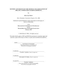
DEVELOPMENT STATUS: ARGO DEEP OCEAN INSTRUMENT PLATFORM<br />
The Deep Suhergence Laboratory is developing<br />
a deep ocean survey and instrument platform<br />
called ABCO. With a design depth of 6,000<br />
meters, ARW vfll be toed on a steel-armored coaxial<br />
cable uhich all rupport aeveral channels<br />
of frequency-multiplued signals. A bsnk of N<br />
cameras in the isaging pod all provide forwrd-.<br />
ride-, and donrlooking views of the ocean<br />
floor. Strobe lighting and LIBEC geometry will<br />
extend the useful range of these cameras to 100<br />
meters. High fidelity acoustic images will be<br />
provided by an integrated side-looking mnar.<br />
Our goal is to create a cohesive and overlapping<br />
data set of wide ruth acoustic images and high<br />
resolution optical images. Presanted here are<br />
~arly results of ARCO-like vehicle towing characteristics<br />
and "ap-shot' oideo systems. Addi-<br />
:ionally, m will describe ABCO's modular design<br />
rpproach Wch affords us the flexibility to in-<br />
:orpotate, in the futwe, additional sensing egr<br />
:ems and a smaller, tethered ROV, JASON.<br />
To sntigfy the needs of oceanographic and<br />
military comurrities, the Deep Submergence Labor-<br />
atory (D.S .L. ) has undertaken the development of<br />
an unmanned march and sump vehicle called<br />
ARGO. Equipped vith a complement of euperior<br />
sensors for deep ocean survey and inspection,<br />
ARW vlll be able to remain eubmerged for long<br />
periods of time measured in terns of days or<br />
weks aad dramatically increase our 'bottom-<br />
staying power" compared to present manned and un-<br />
nanned vehicle operations.<br />
ARGO is a t0-d aled capable of operating to<br />
5000 meters depth. Its tether is a steel-<br />
smored, coaxial cable 0.68 inches in diameter.<br />
Iesigned to tow in a manner similar to D.S.L.'s<br />
WGUS vehicle (Ballard, 19801, ABCO is quite<br />
reavy (greater than 4000 lbs) and will operate<br />
:lose to the bottom. at an altitude less than 70<br />
reters. Our experience vlth ANGUS suggests that<br />
WO, when towd at speeds around 1 knot, will<br />
ily about 100 meters astern of the ship, achiev-<br />
.ng a nearly vertical uire angle.<br />
While providing mechanical support for the<br />
rehicle, ARGO' s tether also carries downlink<br />
--<br />
Stewart E. Harris<br />
William M. Marquet<br />
Robert D. Ballard<br />
-- - .<br />
pomr and a variety of f requency-multiplexed sig-<br />
'rials fro. the onboard mmrs. ARGO is<br />
designed to incorporare scnsars vhich are modular<br />
subeystens. This modularity provides flexibility<br />
for growth and ease of maintenance and develop-<br />
ment. With this technique, w will integrate a<br />
wide-area TV imaging system with a aide-looking<br />
sonar to provide simultaneous broad smth acous-<br />
tic and optical images which will overlap in<br />
coverage and resolution. In addition, other<br />
sensing systems and a mall tethered ROV, JASON,<br />
can be integrated into ABCO, making it a vers-<br />
atile survey and inspection instrument platform.<br />
The purpose of this paper is to describe the<br />
/design and current status of =GO' s development.<br />
CABLE DESIGN<br />
Recent studies on the design of deep sea,<br />
armored coaxial cables (Wilkins, 19838) indicate<br />
the need for an improved version of this all im- '<br />
portant link between operator and remote ve-<br />
hicle. ARCO's tether is a design currently under<br />
consideration as the " standard" for the oceano-<br />
graphic community. It's annor package and in-<br />
ternal structure represents a compromise betwen<br />
. requirements for ruggedness, lov rotation, max-<br />
imum strength, and long flexure lifetime. This<br />
'cable should have a tensile strength in excess of<br />
36,000 lbs. and provide a usable data bandwidth<br />
over 6000 meters of 5 dz.<br />
Although adequate for now, such a cable has a<br />
severe bandwidth limitation vhich w hope to<br />
eliminate using current advances in deep ocean<br />
fiber-optic cables. One de.sign now being pro-'<br />
cured by the Naval Ocean Systems Center-Hawii<br />
(Uilkins, 1983b) incorporates three power con-<br />
ductors and three optical fibers in an armor<br />
package 0.68 inches in diameter, thus offering an<br />
evolution for the ARGO tether which could in-<br />
crease the available bandwidth one hundred fold.<br />
This advantage is important for the integration<br />
of JASON, which has a telemetry requirement of<br />
tw real-time color video channels.<br />
IMAGING SYSTPiS<br />
A primary thrust of the research at D.S.L. is<br />
in deep sea optical imaging, and one goal of<br />
ARCO's first sea trials, scheduled for the summer<br />
of 1984, is to study vide area optical imaging.<br />
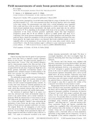
1 * Figure 1 shows an artist's impression of ARGO.<br />
,"Flyingw at an altitude of 50 to 70 meters, ARGO
1 1 illuatnate the ocean floor vith highintensity<br />
strobe lights mounted on the main vehicle.<br />
Suspended 20 to 50 meters bedow ARC0 is<br />
an imaging pod carrying up to five - video<br />
cameras. Four vill be vide angle cameras. Looking<br />
forward, to each side, and straight down,<br />
they dl1 provide us with a componite picture of<br />
an amp 100 to 500 meters qrure. A fifth, focused<br />
telephoto camera vill look down and slightly<br />
forward co obtain detailed information about<br />
the mafloor terrain. The imaged area is illur<br />
trated (not to rde) by the dark trapezoids in<br />
the figure. Thi6 geometry of a light behiad the<br />
camera, (or LIBEC), was pioneered earlier for<br />
film camera sgrcems (Patterson, 1971) and used<br />
succeeefully for march and survey in the FAMOUS<br />
area (Patterson, 1975). By udng low light level<br />
S.I.T. cameras, vith an equivalent wnritivity of<br />
200,000 ASA (byward, 19811, w hope to extend<br />
our visual range capability out to 100 meters<br />
(i.e. four to five optical attenuation lengths).<br />
--<br />
. . .--<br />
XCORE 1: Artist's conception of ARCO towing<br />
configuration<br />
As mentioned, lighting is provided by strobe<br />
lights vhich vi11 flash every few eeconds. In-<br />
stantaneous video pictures, or " mapshots" vill<br />
result. These images are 'grabbed" by electronic<br />
frame stores for viewlng and digital processing.<br />
Because the cameras will cover auch a large area,<br />
pseudo-continuous coverage of the mafloor is<br />
possible by firing the strobe lights often enough<br />
for the images to overlap. Based on a 1 knot<br />
toving speed and 10 second repetition rate, down-<br />
lookina images wuld overlap at least 70%.<br />
--<br />
-<br />
i<br />
In 1981, a ~imilar vide area imaging mystem<br />
was tested on the manned submersible ALVIN in a<br />
aeries of dives off St. Croix. From an altitude<br />
overthe-bottom of 15 to 30 meters vith &robes<br />
nrspended 50 to 100 meters above the sub, w ob-<br />
tained pictures of the aeafloor averaging 2,000<br />
aquare meters in area. Figure 2 is a sample from<br />
this series. &re, a forward-looking camera is<br />
imaging a arbmerged hydrophone towr illuminated<br />
by a strobe light mounced on the tail of the<br />
sub. Taken from an altitude of 21 meters, the<br />
rearlting image captures most of the 15 meter<br />
tall stnrcture vhich is illustrated in Figure 3.<br />
In addition to optical imaging, plans also<br />
call for ride-looldng and perhap s f orwrd-looklag<br />
moors on ARM. Simultaneous acoustic images, up<br />
to 1 Ulometer vide, could be generated from<br />
ARM'S 70 meter altitude. Figure 1 illustrates<br />
this eide-san beam as rall as the Wp-baed<br />
SEABUM moor coverage. Both of these ayatems<br />
provide us with the large geographical picture<br />
vhich is complemented by thd TV coverage, thereby<br />
increasing our understanding and ability to fol-<br />
low the terraln.<br />
I<br />
-<br />
---<br />
FIGURE 2: "Snapshot" video image of BCA<br />
hydrophone cover<br />
Operators on the aurface will interact vith<br />
the imaging and sensor subsystems via a full dup-<br />
lex digital command and control loop. Employing<br />
Lou poux lPicroprocessors and high level soft-<br />
ware, ARC0 subsystems represent a distributed<br />
aetmrk of dedicated processors. Figure 4 i llus<br />
trates the system architecture. The imaging pod<br />
Ls one eubaystem vlth which the operator can<br />
"talk" to via the netmrk node, which is a part<br />
~f the .sequencer. While controlling the node<br />
~peration, the sequencer also cycles the strobe<br />
Lights and can activate the pod cameras direct-<br />
ly. Since our current coaxial cable limits the<br />
lata telemetry to one video channel, multiple<br />
:ameras in the imaging pod are sequenced through<br />
L video svitcher so only one camera is active<br />
hen the lights flash. As subsystems are added,
cney i ~ cie ~ lnco l the node, powr distribucion,<br />
and clock network and ecnd their data to the telemetrp<br />
system for uplinking to the control canter<br />
on the ship.<br />
SURFACE SUPPORT EQUIPMENT<br />
At1 subsurface data is acquired in a control<br />
center vNch is containerized for eaoy trans-<br />
portation and inataUation on oceanographic ves-<br />
sels. Equipment for real-time processing and<br />
viewing as ell as recordiag for poet-mfssion<br />
processing and archival is located in the control<br />
center. Three operators will bc responsible for<br />
the operation of ARCO, the vlnch vstea and con<br />
of the ship. Video, sonar, and navigation data<br />
are available for guidance of the shfp. As each<br />
image is tranclplitted up thc wire and displayed,<br />
the user dl1 describe the terrain he sees using<br />
a 10,000 frame imaging library to assist him in<br />
standardizing his observations. This library is<br />
stored as still framer on video discs which pro-<br />
vide random accerr and the potential for mosaic ,<br />
production. Onboard video editing capabilities<br />
allov production of hourly, daily, and mission<br />
wary tapes in an effort to reduce the amount .<br />
of TV data to manageable proportions.<br />
Eventually w hope to integrate dynamic posi-<br />
tioning of the ship and finally global position-<br />
ing navigation inco the ABCO control center.<br />
Users will have access to a vide variety of other<br />
inf ormetion, including three-dimensional imaging<br />
of SEABEAM data, real-time displays of vehicle<br />
orientation in x, y, and z and a summary of his<br />
observations along track (x, y, and depth versus<br />
i<br />
distance). As the operacion becomes routine,<br />
ARCO will wrk 24 hours a day, maklng it an ef-<br />
- fective tool for deep ocean exploration.<br />
---<br />
'ICURE 4: ARC0 cwauxnd and control arc~tecture<br />
TNs wrlc is funded under ONR Contract No.<br />
NOOOl4-82-C-0743.<br />
1. Ballard, R.D., Mapping the Mid-Ocean Ridge,<br />
12th Annual Off shore Technology Conference<br />
in Houston, TX, Nay 5-8, 1980.<br />
2. Wilkins, C., Specification for the<br />
Fabrication of an Armored Deep Sea Coaxial<br />
Cable, personal communication, 1983a.<br />
3. Wilkins, C., Specification for the<br />
Fabrication of a Prototype, Deep Sea,<br />
Electro-Optical, Tether Cable, personal<br />
comuaication, 1983b.<br />
4. Patterson, B.B., Increased Ranges for<br />
Conventional Undermter heras, Pro-<br />
ceedings of the Society of Photo-Optical<br />
Instrumentation Engineers, 2: 253, 1971.<br />
5. Patterson, R.B., LIBEC System Engineering,<br />
Marine Technology Society Journal, 2,<br />
(10): 3, 1975.<br />
6. Hayard, C.G., Enhanced Inspection by Nev<br />
Photo and lV Techniques, International<br />
Underwater Systems Design, 3, (6): 15,<br />
1981.
Developed by the Deep Submergence Laboratory of the<br />
Woods Bole Oceanographic Institution, ARGO is an<br />
unmanned instrument platform designed for deep<br />
ocean search and survey. Integrating both visual<br />
and acoustic imaging techniques for real-time<br />
viewing, ARGO is a system which provides con-<br />
tinuous, around-the-clock operation for seafloor<br />
exploration. With a design depth of 6,000 meters,<br />
it is toved on a steel-armored coaxial cable which<br />
supports several channels of frequency-multiplexed<br />
signals. In addition, surface support is highly<br />
integrated, bringing together ship control, naviga-<br />
tion, and vehicle operation into a transportable<br />
control center.<br />
In our expedition that found the TITANIC, this<br />
system was tested for the first time and proved<br />
itself by delivering the exciting pictures of the<br />
famous shipvreck lying on the bottom of the ocean.<br />
This paper will briefly describe ARGO and the<br />
reasons for its development. Examples of ARGO<br />
imaging from our first year of operation will<br />
demonstrate how modern oceanographers remotely<br />
sense the ocean floor.<br />
ARGO was developed to satisfy the needs of the<br />
oceanographic and military communities. It is an<br />
unmanned search and survey vehicle (Pigure 1)<br />
capable of operating to 6,000 meters depth. Its<br />
tether is a steel armored, coaxial cable .68 inches<br />
in diameter. Designed to tow in a manner similar<br />
to DSLfs Acoustically Navigated Geophysical<br />
Underwater Survey (ANGUS) vehicle, ARGO weighs more<br />
than 4,000 pounds and operates at altitudes of 20<br />
to 40 meters. When ARGO is towed at speeds of<br />
approximately 1 knot, it flies about 100 meters<br />
astern of the ship, achieving a nearly vertical<br />
wire angle. When the vehicle is operated from a<br />
versatile ship, such as the R/V RNORR, ve are able<br />
to position it very precisely using only the ship's<br />
' propulsion system to maneuver the vehicle on the<br />
bottom. ARGO has no independent propulsion<br />
capabilities.<br />
While providing mechanical support for the vehicle,<br />
ARGO1s tether also carries power to the vehicle and<br />
a variety of signals from the sensors on board the<br />
vehicle which are modular subsystems. This<br />
modularity provides flexibility for growth and ease<br />
of maintenance and develooment. A wide area TV<br />
ARGO: CAPABILITIES FOR DEEP OCEAN EXPLORATION<br />
Stewart E. Harris<br />
Robert D. Ballard<br />
Deep Submergence Laboratory<br />
Woods Hole Oceanographic Institution<br />
Woods ole;<br />
Reference 2<br />
Figure 1. Photo of ARGO during tests at the WE01<br />
dock. The vehicle weighs 2 tons and is 15 feet<br />
long, 3.5 feet tall and 3.5 feet vide.<br />
imaging system is integrated with side-looking<br />
sonar using this technique. This provides simul-<br />
taneous broad swath acoustic and optical images<br />
that overlap in coverage and resolution.<br />
CABLE DBSIa<br />
ARGOts tether is the standard for the oceanographic<br />
community. Its armor package and internal struc-<br />
ture represent a compromise among the requirements<br />
for ruggedness, low rotation, maximum strength, and<br />
long flexure lifetime. This cable has a tensile<br />
strength in excess of 36,000 pounds and provides a<br />
usable bandwidth of 5 megahertz over a 6,000-meter<br />
length. In this case, "usable" means that signal<br />
attenuation is less than a factor of 10,000. A<br />
sophisticated telemetry system allows us to multi-<br />
plex the video, sonar, and power into this severely<br />
limtted bandwidth.<br />
ARGO presently carries one forward-looking TV<br />
camera, one down-looking, and a down-looking<br />
telephoto. These are all carried on the forward<br />
end of the vehicle, as shown in Pigure 2. The<br />
strobes and incandescent lights which ARGO uses to<br />
illuminate the ocean floor are carried in the after<br />
end of the vehicle. This arrangement is intended<br />
to maximize the horizontal separation between the<br />
cameras and the light sources. Computer simula-<br />
tions have shovn that by increasing this separa-
tion, the amount of backscatter can be sig-<br />
nificantly decreased. This in turn increases the<br />
altitude from which high-quality pictures can be<br />
obtained. Tests have shown that this geometry<br />
makes it possible to get high-quality images from<br />
an altitude of 35 meters in clear water using the<br />
strobe lights for illumination. At lower altitudes<br />
(around 10 meters) simultaneous film snapshots can<br />
be taken.<br />
The shape of the imaged area achieved by ARGO1s<br />
cameras is shown in Figure 3. By using low-light-<br />
level Silicon Intensified Target (SIT) cameras, our<br />
swath capability extends to 56 meters at 35-meter<br />
altitudes.<br />
The high quality of video images obtained using the<br />
horizontal separation of cameras and light sources<br />
was verified during tests of of the ARGO conducted<br />
in the North Atlantic during September of 1985.<br />
During these tests good quality images were ob-<br />
tained in very murky water from altitudes of 15<br />
meters. Figure 4 is an example of one of those<br />
images. This figure is a photographic still of a<br />
video image, so the resolution is lower than that<br />
available with film, and there is some blurring due<br />
to noise. The latter is emphasized when the video<br />
is frozen into a still image. This particular<br />
image is from the sequence which gave us our first<br />
verifiable evidence that we had actually discovered<br />
the TITANIC.<br />
In addition, a simultaneous 100 KHz, side-looking<br />
sonar provides a lower resolution image of the<br />
surrounding terrain for a distance of 350 meters on<br />
each side. The optical and acoustic images comple-<br />
ment one another: the sonar provides the large<br />
geographical picture while the video provides<br />
detail which facilitates the interpretation of the<br />
sonar images.<br />
ARGO '85<br />
SIDE SECTION<br />
Figure 2. Schematic of ARGO showing the placement<br />
of the various components.<br />
ADDITIONAL SXNSORS<br />
Since ARGO is intended to be a multifunctional<br />
sensor platform, additional telemetry channels are<br />
integrated to support a variety of needs. At<br />
present, vehicle attitude parameters such as al-<br />
titude, depth, heading, pitch, and heave are<br />
digitized and transmitted to the surface where the<br />
data is annotated on the video image to assist<br />
operation. Other digital channels are available<br />
for this type of low bandwidth sensor. In addi-<br />
tion, audio quality analog channels are available<br />
for sensor data. These have been used for a<br />
<strong>Argo</strong> '85<br />
Forward-Looklng Nornal<br />
w<br />
Tele hot0<br />
Down-Looktng Wlde Angle<br />
Figure 3. Footprint of ARGO1s three TV cameras<br />
showing the area seen on the bottom from a 20 meter<br />
altitude.
Figure 4. A video still of an ARGO TV image taken<br />
during the TITANIC survey. Object is one of<br />
TITANIC'S boilers as seen laying upright on the<br />
bottom through a telephoto lens. The boiler is<br />
about 4.8 meters in diameter.<br />
variety of devices such as hydrophones, transmis-<br />
siometer and temperature probe. The goal is for<br />
ARGO to support an 'arbitrary science package by<br />
providing power and digital or analog channels for<br />
downlink control and data uplink.<br />
SUBPACE SUPPORT<br />
The real-time image processing system developed by<br />
DSL for use in the ARGO system takes advantage of<br />
state-of-the-art digital techniques for image<br />
enhancement to provide improved images, increasing<br />
user and operator understanding.<br />
As each image is transmitted up the wire and<br />
diplayed, the user describes the terrain he sees<br />
using a 10,000-frame imaging library to assist him<br />
in standardizing his observations. This library is<br />
stored as still frames on video discs which provide<br />
random access and the potential for mosaic<br />
production. On board video editing capabilities<br />
allow production of hourly, daily, and mission<br />
summary tapes in an effort to reduce the amount of<br />
TV data to manageable proportions.<br />
Equipment for real-time processing and viewing, as<br />
well as for recording for post-mission processing<br />
and archiving, is located in the control center,<br />
which is containerized for easy transportation and<br />
installation on oceanographic vessels.<br />
Three operators are responsible for the operation<br />
of ARGO, the winch system, and navigation. Video,<br />
sonar and navigation data are available for use in<br />
the guidance of the ship. Eventually, we will<br />
integrate dynamic positioning of the ship, and<br />
finally global positioning navigation into the ARGO<br />
control system. Operators also will have access to<br />
a wide variety of other information, including<br />
three-dimensional imaging of Seabeam data. (a com-<br />
mercial, highly sophisticated topographical mapping<br />
system), real-time displays of vehicle orientation,<br />
and a summary of observations along the track of<br />
the vehicle. In the future, other sensing systems<br />
and a small, tethered, remotely-operated vehicle,<br />
JASON, will be integrated into ARGO, which will<br />
increase its ability to project man's senses to the<br />
bottom of the sea.<br />
This work was funded and supported by the Office of<br />
Naval Research, Contract No. N00014-82-C-0743.<br />
We would like to thank the officers and crew of the<br />
R/V KNORR for their help during the expedition.<br />
Lastly, we thank the engineering and technical<br />
staff of the Deep Submergence Laboratory for their<br />
magnificent job in building and operating ARGO.
, ~ccep~ea ror Publication, AUVS Conterence Proceedings, Boston, 1986.<br />
ARGO/JASON: Integrated Capabilities for Exploration of the Seaf loor<br />
Stewart E. Harris<br />
Dana R. Yoerger<br />
Deep Submergence Laboratory<br />
Department of Ocean Engineering<br />
Voods Hole Oceanographic Institution<br />
Woods Hole, HA 02543<br />
ABSTR4m<br />
ARGO/JASON is a remotely operated deep ocean exploration system under<br />
development at the Voods Hole Oceanographic Institution. Towed from a<br />
surface ship using a steel-armored electro-mechanical or electro-optical<br />
cable at depths up to 6000 meters, ARGO/JASON is a pair of unmanned vehicles<br />
with complementary capabilities.<br />
ARGO is an unmanned instrument platform designed for large area search<br />
and survey. The first vehicle of its kind to fully integrate both visual<br />
and acoustic imaging for real-time viewing, ARGO is a system that provides<br />
continuous, around-the-clock operation for seafloor exploration. In our<br />
recent expedition that found the TITANIC, this system was tested for the<br />
first time and proved itself by delivering the exciting pictures of the<br />
famous shipwreck lying on the bottom of the ocean at nearly 4000 meters.<br />
JASON is a free swimming, remotely operated vehicle that will be<br />
tethered to ARGO. JASON will complement ARGOts wide area survey<br />
capabilities with the ability to inspect objects closely and to perform<br />
manipulative tasks. JASON will feature dual manipulators, still and video<br />
cameras, and a variety of scientific payloads. A supervisory control system<br />
will permit precise movements of both cameras and manipulators from high<br />
level commands by the human operators on the surface.<br />
This presentation will cover the history of ARGO/JASON, the reason for<br />
its development and will describe the future of this technology. Bottom<br />
Reference 3
footage of the TITANIC and scenes from the expedition will be presented to<br />
describe the operation of the system and to document its performance.<br />
ARGO<br />
ARGO was developed to satisfy the needs of the oceanographic and<br />
military communities. It is an unmanned search and survey vehicle capable<br />
of operating to 6,000 meters depth. Its tether is a steel armored, coaxial<br />
cable .68 inches in diameter. Designed to tow in a manner similar to DSLfs<br />
Acoustically Navigated Geophysical Underwater Survey (ANGUS) vehicle, ARGO<br />
weighs more than 4,000 pounds and operates at altitudes of 20 to 40 meters.<br />
When ARGO is towed at speeds of approximately 1 knot, it flies about 100<br />
meters astern of the ship, achieving a nearly vertical wire angle. When the<br />
vehicle is operated from a versatile ship, such as the R/V KNORR, we are<br />
. able to position it very precisely using only the ship's propulsion system<br />
to maneuver the vehicle on the bottom. ARGO has no independent propulsion<br />
capabilities.<br />
While providing mechanical support for the vehicle, ARGO1s tether also<br />
carries power to the vehicle and a variety of signals from the sensors on<br />
board the vehicle which are modular subsystems. This modularity provides<br />
flexibility for growth and ease of maintenance and development. A wide area<br />
TV imaging system is integrated with side-looking sonar using this<br />
technique. This provides simultaneous broad swath acoustic and optical<br />
images that overlap in coverage and res'olution.<br />
CABLE DESIGN<br />
ARGO1s tether is the standard for the oceanographic community. Its<br />
armor package and internal structure represent a compromise among the<br />
, requirements for ruggedness, Pow rotation, maximum strength, and long<br />
flexure lifetime. This cable has a tensile strength in excess of 36,000
pounds and the coax core provides a usable bandwidth of.5 megahertz over a<br />
6,000-meter length. In this case, llusable" means that signal attenuation is<br />
less than a factor of 10,000. A sophisticated telemetry system allows us to<br />
multiplex the video, sonar, and power into this severely 1imit.ed bandwidth.<br />
InAGING SYSPEnS<br />
ARC0 presently carries one forward-looking TV camera, one down-looking,<br />
and a down-looking telephoto. These are all carried on the forward end of<br />
the vehicle, as shown in Figure I. The strobes and incandescent'lights<br />
which ARGO uses to illuminate the ocean floor are carried in the after end<br />
of the vehicle. This arrangement is intended to maximize the horizontal<br />
separation between the cameras and the light sources. Computer simulations<br />
have shown that by increasing this separation, the amount of backscatter can<br />
be significantly decreased. This in turn increases the altitude from which<br />
high-quality pictures can be obtained. Tests have shown that this geometry<br />
makes it possible to get high-quality images from an altitude of 35 meters<br />
in clear water using the strobe lights for illumination. At lower altitudes<br />
(around 10 meters) simultaneous film snapshots can be taken.<br />
The shape of the imaged area achieved by ARGOfs cameras is shown in Figure<br />
4. By using low-light-level Silicon Intensified Target (SIT) cameras, our<br />
swath capability extends to 56 meters at 35-meter altitudes.<br />
The high quality of video images obtained using the horizontal<br />
separation of cameras and light sources was verified during tests of of the<br />
ARGO conducted in the North Atlantic during September of 1985. During these<br />
tests good quality images were obtained in very murky water from altitudes<br />
of 15 meters. This expedition ultimately led to .the discovery of the<br />
.TITANIC which had been lost for 73 years.
E<br />
' In addition, a simultaneous 100 KHz, side-looking sonar provides a<br />
lower resolution image of the surrounding terrain for a distance of 350<br />
meters on each side. The optical and acoustic images complement one<br />
another: the sonar provides the large geographical picture while the video<br />
provides detail which facilitates the interpretation of the sonar images.<br />
ADDITIOHAL SENSORS<br />
Since ARGO is intended to be a multifunctional sensor platform,<br />
additional telemetry channels are integrated to support a variety of needs.<br />
At present, vehicle attitude parameters such as altitude, depth, heading,<br />
pitch, and heave are digitized and transmitted to the surface where the data<br />
is annotated on the video image to assist operation. Other digital channels<br />
are available for this type of low bandwidth sensor. In addition, audio<br />
quality analog channels are available for sensor data. These have been used<br />
for a variety of devices such as hydrophones, ttansmissiometer and<br />
temperature probe. The goal is for ARGO to support an arbitrary science<br />
package by providing user power and either digital or analog channels for<br />
downlink control and data uplink.<br />
SURPACE SUPPORT<br />
The real-time image processing system developed by DSL for use in the<br />
ARGO system takes advantage of state-of-the-art digital techniques for image<br />
enhancement to provide improved images, increasing user and operator<br />
understanding.<br />
As each image is transmitted up the wire and displayed, the user<br />
describes the terrain he sees using a 10,000-frame imaging library to assist<br />
him in standardizing his observations. This library is stored as still<br />
hames on video discs which provide random access and the potential for<br />
mosaic production. On board video editing capabilities allow production of
In addition, a simultaneous 100 KHz, side-looking sonar provides a<br />
lower resolution image of the surrounding terrain for a distance of 350<br />
meters on each side. The optical and acoustic images complement one<br />
another: the sonar provides the large geographical picture while the video<br />
provides detail which facilitates the interpretation,of the sonar images.<br />
ADDITIONAL SENSORS<br />
Since ARGO is intended to be a multifunctional sensor platform,<br />
additional telemetry channels are integrated to support a variety of needs.<br />
At present, vehicle attitude parameters such as altitude, depth, heading,<br />
pitch, and heave are digitized and transmitted to the surface where the data<br />
, is annotated on the video image to assist operation. Other digital channels<br />
are available for this type of low bandwidth sensor. In addition, audio<br />
\ quality analog channels are available for sensor data. These have been used<br />
for a variety of devices such as hydrophones, transmissiometer and<br />
temperature probe. The goal is for ARGO to support an arbitrary science<br />
ucec c ;+he r<br />
package by providing power and digital or analog channels for downlink<br />
4 A<br />
control and data uplink.<br />
SURFACE SUPPORT<br />
The real-time image processing system developed by DSL for use in the<br />
ARGO system takes advantage of state-of-the-art digital techniques for image<br />
enhancement to provide improved images, increasing user and operator<br />
understanding.<br />
- As each image is transmitted up the wire and displayed, the user<br />
describes the terrain he sees using a 10,000-frame imaging library to assist<br />
him in standardizing his observations. This library is stored as still<br />
frames on video discs which provide random access and the potential for<br />
mosaic production. On board video editing capabilities allow production of
hourly, daily, and mission summary tapes in an effort to reduce the amount<br />
of TV data to manageable proportions.<br />
Equipment for real-time processing and viewing, as well as for<br />
recording for post-mission processing and archiving, is located in the<br />
control center, which is containerized for easy transportation and<br />
installation on oceanographic vessels.<br />
Three operators are responsible for the operation of ARGO, the winch<br />
system, and navigation. Eventually, we will integrate dynamic positioning<br />
of the ship, and finally global positioning navigation into the ARGO control<br />
system. In the future, other sensing systems and a small, tethered,<br />
remotely-operated vehicle (ROV), JASON, will be integrated into ARGO.<br />
J W N<br />
Small, tethered ROV1s are currently limited in their ability to perform<br />
manipulative tasks. A research program is currently underway to improve the<br />
capabilities of a small vehicle equipped with manipulators through the<br />
design of a supervisory control system. The goal is to approach the<br />
versatility of a human diver, rather than to develop capabilities for<br />
specific tasks. The supervisory control system will allow the operator to<br />
control the vehicle and manipulator motions in a coordinated fashion.<br />
Control system and man-machine interface issues will be investigated using<br />
computer simulation and an experimental vehicle system consisting of a<br />
modified Benthos RPV-430 and a Deep Ocean Engineering manipulator. A direct<br />
result of this work will be the supervisory control system for the JASON<br />
vehicle.<br />
The JASON system will operate from the towed ARGO vehicle,<br />
complementing the acoustic and optical search and survey systems of ARGO.<br />
The resulting vehicle system will integrate a large area survey capability
-e<br />
I with a small maneuverable inspection vehicle capable of dexterous<br />
manipulation. This integrated approach will allow the exploration of the<br />
ocean floor to be accomplished in a more productive manner than the current<br />
. mix of towed unmanned vehicles and manned submersibles. Specifically, JASON<br />
-<br />
.<br />
*r<br />
will be applied to the detailed exploration of the Hid-Ocean Ridge system,<br />
the largest but one of the least understood geologic features on Earth.<br />
THE JASON OPKRATIONAL SCENARIO<br />
After ARGO has located an area of interest, such as a hydrothermal vent<br />
system, ARGO will be dynamically positioned using a control system currently<br />
under development at the Deep Submergence Laboratory. Then, JASON will be<br />
deployed and maneuvered to the worksite. Typical tasks include close-up<br />
video and still photography, collection of samples, as well as the<br />
deployment and recovery of instruments and sensors. This concept is shown<br />
in Figure 3.<br />
While outside of ARGO, JASON will be tracked using both acoustic and<br />
optical methods. Short baseline acoustic navigation carried aboard ARGO<br />
will be used to locate both vehicles relative to a single bottom<br />
transponder. Also, the optical imaging capability of ARGO will be used to<br />
track both JASON and its tether. These complementary navigation methods<br />
should allow JASON to work in a variety of difficult environments such as<br />
those encountered in mountainous underwater terrain.<br />
JASON will communicate to the surface through the ARGO telemetry<br />
system. Both ARGO and JASON will eventually employ fiber-optic telemetry to<br />
provide high bandwidth. For JASON, the use of fiber-optics will also allow<br />
the tether to be very small and' flexible.<br />
Currently, underwater manipulative tasks are usually performed by<br />
fixing the vehicle to the worksite, either by resting on the bottom or
through the use of grabber arms. Then the task is completed using a<br />
manipulator arm with a large number of functions, typically six or more. .<br />
This approach is commonly used for tasks such as salvage and recovery or<br />
cleaning and inspection of structures.<br />
Simpler manipulative tasks can often be accomplished with some small<br />
vehicles by fixing the manipulator arm in an appropriate configuration and<br />
exploiting the vehicle's maneuverability. Observation type ROV's are often<br />
used with two or three function manipulators in'this fashion to cut lines,<br />
untangle the vehicle's tether, etc.<br />
JASON will use neither of these approaches, but will allow the operator<br />
to simultaneously control both the motions of the vehicle and manipulators<br />
in a coordinated fashion. This will allow general, six degrees-of-freedom<br />
motion of the manipulator and end effector with an arm having only a few<br />
functions. A simpler manipulator will result in the overall system being<br />
smaller, cheaper, more reliable, and decrease the required power.<br />
This approach seems especially appropriate in deep ocean work, where<br />
currents seldom exceed a small fraction of a knot and the need to reduce<br />
size, complexity, and power is great. However, many unanswered questions<br />
remain concerning the design of such a control system, sensors, and man-<br />
machine interface.<br />
JASON CONTROL SYSTEM<br />
In supervisory control, a computer interacts directly with a process<br />
while a human operator manages the system. The foundations of the<br />
supervisory control system for an ROV will be closed-loop trajectory<br />
controllers.Closed-loop control'of manipulator functions is common in the<br />
offshore industry today, and servo-controlled arms are available from<br />
several manufacturers. However, closed-loop control of vehicle translation
is not available, although automatic depth and altitude controls are found<br />
on many vehicles. In addition to a good control system, the vehicle and its<br />
sensors must be well designed to give good performance.<br />
,<br />
HOW DO WE DESIGN $N' ROV UITE A PREDICTABLE LBVBL OF CONTROL PERFORHANCE?<br />
Path following performance for an ROV is difficult to quantify through<br />
analysis. Generally, the speed of response and the tracking precision will<br />
be limited by a variety of factors, including sensor performance,<br />
disturbances, and the dynamic characteristics of the vehicle. Due to the<br />
nonlinear nature of underwater vehicle dynamics, existing linear control<br />
system design techniques are poorly suited to providing an understanding of<br />
an automated ROV.<br />
Performance may also be measured in ways that have no direct<br />
relationship to tracking accuracy or response items. For instance, in the<br />
deep ocean application of JASON, quality continuous color video is a high<br />
priority. Therefore, a steady camera platform is essential. The<br />
characteristic attitude oscillations common to most ROVs constitute poor<br />
performance.<br />
Tracking performance limitations for an ROV control system can come<br />
from a variety of sources. The available navigation sensors have limited<br />
precision and update rates and many have intrinsic time delays. The<br />
dynamics of an ROV are highly nonlinear and difficult to model precisely.<br />
Finally, the ROV is subjected<br />
'Y<br />
to many disturbances such as forces induced by<br />
- currents and a tether. In some cases, computational power may be limited.<br />
>*<br />
J<br />
We are currently developing control system design tools that project<br />
the closed-loop performance of an ROV given simple descriptions of the<br />
'limiting factors. These techniques reveal how the different limiting<br />
factors interact, permitting the designer to concentrate on those elements
. n F<br />
1<br />
I<br />
'\<br />
that affect performance most. The techniques can save both effort and cost<br />
by allowing simplified dynamic models to be used for the control system<br />
design while guaranteeing stability and achieving a defined level of<br />
performance.<br />
The basis for this work is a robust control technique for nonlinear<br />
systems called sliding control. Sliding control theory [2,3] and details of<br />
its application to underwater vehicles [1,4,5] can be found in the<br />
references .<br />
An outline of the sliding control design procedure is shown in Figure<br />
4. There are three inputs to the design process: specification of the<br />
desired closed-loop dynamics; approximate dynamic model of the vehicle; and<br />
estimates of the uncertainties in the model. The design method not only<br />
produces simple controllers that perform well, but also directly provides<br />
information about system performance given a description of the limiting<br />
factors.<br />
The desired closed-loop dynamics are typically specified to be those of<br />
a Pow-order, linear system (e.g., first order linear, critically damped<br />
linear second-order system, etc.). In each case, the desired "targetw<br />
dynamics will have a low-pass characteristic with a specified bandwidth.<br />
The closed-loop system will not be expect.ed to respond infinitely fast. The<br />
bandwidth limit reflects basic limitations of the system and may originate<br />
from several sources including navigation system specifications, actuator<br />
and power limits, unmodelled vehicle dynamics, and disturbances.<br />
In addition to the desired or target dynamics, the open loop dynamics<br />
) of the vehicle must also be specified. This model can contain nonlinear<br />
terms for the drag effects, and may also include time-varying added mass
terms. This control system design technique is completely compatible with<br />
- the types of models produced by hydrodynamic analysis.<br />
7<br />
a the<br />
I<br />
1<br />
Another input consists of estimates of the uncertainty in the dynamic<br />
model. These estimates may also be in nonlinear form and account for<br />
uncertainties in model parameters, structural simplifications of the model,<br />
and disturbances.<br />
This technique summarizes performance in a powerful way in a nonlinear<br />
context. Any control system design technique will allow evaluation of<br />
closed-loop bandwidth and disturbance responses, but sliding control<br />
\ provides a single unified metric for each degree of freedom that combines<br />
effect of bandwidth limitations and dynamic uncertainty.<br />
Sliding techniques permit a nonlinear dynamic model to be used directly<br />
to design a closed-loop system with no need for linearization. This suits<br />
the ROV control problem well, since the vehicle dynamics are highly<br />
nonlinear and there are no obvious operating points about which to linearize<br />
the model [6].<br />
ROVs typically move in all directions, so linearizing about values of<br />
1- forward speed is not the best approach. Designing a stable controller using<br />
the nonlinear model directly simplifies the design and implementation of the<br />
controller and gives more uniform behavior over the entire range of<br />
operation.<br />
An error metric and a time-varying envelope of its expected bounds,<br />
both integral to the control computation, provide simple confirmation that<br />
the controller is operating as expected, and give a direct, continuous<br />
measure of controller performance.
EXPERIHENTAL RESULTS: POOL TEST<br />
Trials using the Benthos RPV-430 ROV in a pool demonstrated closed-loop<br />
vehicle control in a trajectory tracking task [I]. Those tests used a<br />
sliding controller running at 10 Hz to fly predetermined paths. A prototype<br />
Applied Sonics SHARPS navigation system with repeatability of a few<br />
millimeters was used for position feedback [7]. The SHARPS (Sonic High<br />
Accuracy Ranging and Positioning System) consists of a set of hard-wired<br />
receivers placed in a net with a transmitter on the vehicle.<br />
These tests showed that following a trajectory with high accuracy is<br />
possible using sliding control. Figure 5 shows desired and measured<br />
positions while following a rectangular trajectory in the pool. Errors in<br />
position were generally less than two inches. Speeds during this trial<br />
were 1.1 feet per second.<br />
Figure 6 shows the error metric, s, for the controller, staying within<br />
the "boundary layer", indicating that uncertainties have been adequately<br />
bounded. The model used had 50% uncertainty in both drag coefficient and<br />
effective mass. A more refined model would be directly reflected in both<br />
the metric s and the boundary layer thickness 9.<br />
The uncontrolled pitch and roll modes of the RPV, at about 0.4 Hz, were<br />
found to limit bandwidth as these modes were coupled to translation.<br />
Therefore, the bandwidth of the controller had to be limited to well below<br />
0.4 Hz.<br />
APPLICATION TO JASON<br />
Via sliding control, we have developed some concepts regarding what<br />
constitutes "good" vehicle design from a control perspective. Generally<br />
these concepts would also improve vehicle performance using other closed-<br />
loop design methods of manual control.
These concepts are being employed to make JASON a productive scientific<br />
instrument. Components and techniques are being refined in shallow water<br />
tests using the RPV-430 vehicle. This summer we expect to test the RPV in<br />
high currents to investigate high-bandwid th and adaptive control techniques<br />
for both the vehicle and manipulator.<br />
ACRNO-S<br />
This work was sponsored by the Office of Naval Research, Contract No.<br />
N00014-84-K-0070, N00014-82-C-0743, N00014-85-C-0410. Haterial support was<br />
also received from IBH and Applied Sonics, Inc., Gloucester, Virginia, USA.
REFERENCES<br />
1. D.R. Yoerger, J.B. Newman, J.-J.E. Slotine, Supervisory Control System<br />
for the JASON ROV, to appear, IEEE J. Oceanic Eng., 1986.<br />
2. J.-J.E. Slotine, Tracking Control of Nonlinear Systems Using Sliding<br />
Surfaces, Ph.D. Thesis, MIT Dept. of Aero. and Astro., May 1983.<br />
3. J.4.E. Slotine, The Robust Control of Robot Manipulators, Int. J.<br />
Robotics Res., Vol. 4, No. 2.<br />
4. D.R. Y.oerger, J.-J.E. Slotine, Robust Trajectory Control of Underwater<br />
Vehicles, IEEE 3. Oceanic Eng., Vol. OE10, #4, October 1985.<br />
5. D.R. Yoerger, J.B. Newman, Demonstration of Closed-Loop Trajectory<br />
Control of an Underwater Vehicle, Proc. Oceans 85, IEEE/MTS,<br />
San Diego, 1985.<br />
6. D.H. Lewis, J.M. Lipscombe, P.G. Thomasson, The Simulation of Remotely<br />
Operated Vehicles, Proc. ROV 84, MTS, 1984.<br />
7. D.A. Hahn, G.N. Williams, M. Wilcox, P. Wilcox, A Computerized High<br />
Resolution Underwater Triangulation Mapping System, Proc.<br />
Oceans 85, MTS, 1985.
ARGO '85<br />
SIDE SEcnorv<br />
FIGURE 1: Schematic of ARGO showing the placement of the various components.<br />
1<br />
Forward-Looking Normal<br />
Down-Looklng Wide Angle<br />
/7<br />
Figure 2: Footprint of ARGO's three TV cameras showing the area seen on<br />
the bottom from a 20 meter altitude.
FIGURE 3: JASON will be deployed while ARGO and the surface vessel are<br />
dynamically positioned. JASON will be tracked both acoustically<br />
and optically from ARGO.<br />
I<br />
Nonlinear<br />
Model<br />
Desired Model<br />
Dynamics Uncertainty<br />
Quantitative Controller<br />
Predictions Design and<br />
of Performance Implementation<br />
FIGURE 4: A summary of the sliding control design method. Given an<br />
approximate dynamic model of the vehicle, a desired dynamic<br />
characteristic, and estimates of model uncertainty, the performance<br />
of +ha plficarl-Inno ----&-- --- ' . -
Commanded and Measured Position<br />
feet<br />
-10 1<br />
- 10 -5 0 5 10<br />
feet .,.<br />
FIGURE 5: Commanded position (plain line) and measured position (with<br />
ticks) from an automatic control test in a pool. X direction<br />
is to the right. Position errors do not exceed a few inches.<br />
S<br />
S t rajectory<br />
I I I I I I I I<br />
5 10 15 20 25 30 35 40 45 50<br />
time<br />
FIGURE 6: The error metric for the X direction during the automatic control<br />
test. A time-varying envelope (called the "boundary layer") is also<br />
shown. The error metric (called "s") is guaranteed to remain<br />
inside the boundary layer if uncertainty is bounded correctly.
ABSTRACT<br />
DmONSTiUTION OF SUPERVISORI CONTROL FOR ROV'S AND MANIPULATORS<br />
JASON is an ROV for deep ocean scientific tasks<br />
currently under development at the Deep<br />
Submergence Laboratory of the Woods Hole<br />
Oceanographic Institution. A key element of the<br />
vehicle will be a supervisory control system that<br />
coordinates the movements of the vehicle and<br />
manipulators, allowing more complex and precise<br />
tasks to be performed.<br />
In this paper, the low level control system that<br />
provides precise positioning of the vehicle is<br />
described. These closed loop controllers underlie<br />
the higher level supervisory functions such as<br />
planning, teaching and monitoring.<br />
The control system is designed to deal with the<br />
specific problems of undervater vehicles and<br />
manipulators, including nonlinear and imprecise<br />
models, coupling between movements, noisy<br />
measurements, and limited computational power.<br />
The control system is very general, and is readily<br />
adaptable to different vehicles and manipulator<br />
systems. Simulation results for a Benthos RPV-430<br />
vehicle are presented.<br />
INTRODUCTION<br />
The Deep Submergence Laboratory of the Woods Hole<br />
Oceanographic Institution is currently designing<br />
JASON, an ROV for deep ocean scientific<br />
applications. Deployed from the ARC0 wide area<br />
swey vehicle [I], JASON will act as the eyes and<br />
hands of the scientists aboard the research<br />
vessel. One emphasis in the JASON program is the<br />
refinement of supervisory control techniques.<br />
JASON will be one member of a family of vehicles<br />
developed a d operated by DSL for the exploration<br />
of the Mid-Ocean Ridge. Other DSL assets include<br />
several sidescan sonars, video survey systems, and<br />
photographic systems. A l l systems operate to<br />
depths of 2000 ft. (6000m).<br />
The Deep Submergence Laboratory has an ongoing<br />
<strong>Program</strong> of research in the control system<br />
techniques that vill make vehicles like JASON more<br />
capable and easier to operate. JASON will include<br />
a control system that allows the motions of the<br />
vehicle and the manipulators to be controlled and<br />
coordinated. Vehicle attitude and position as<br />
well as manipulator position 'will be controlled by<br />
very precise automatic control loops.<br />
Dana A. Yoerger James B. Nevman<br />
Deep Submergence Laboratory<br />
Department of Ocean Engineering<br />
Woods Hole Oceanographic Institution<br />
Woods Hole, Massachusetts 02543<br />
Reference 4<br />
A supervisory control systeo that includes control<br />
of vehicle translation can improve a vehicle's<br />
capability substantially, particularly for<br />
manipulation tasks. For a small ROV, closed<br />
loop control of vehicle translation will allow the<br />
vehicle motions to compliment the manipulator<br />
movements, reducing the need for heavy grabber<br />
arms to hold the vehicle on station. Taking<br />
advantage of vehicle movement can also reduce the<br />
number of manipulator degrees of fretdom required<br />
to execute a specific task. The resulting<br />
decrease in vehicle size, weight, power, and<br />
mechanical complexity are especially attractive<br />
for a full ocean depth vehicle such as JASON.<br />
Although automatic depth and attitude controls are<br />
commonly found on many vehicles, full closed loop<br />
control of translational position and velocity<br />
requires that many difficult problems be solved.<br />
An automatic control system relies on measurements<br />
or estimates of the vehicle state. To control the<br />
position of a vehicle, good estimates of both<br />
position and velocity are required. The most<br />
practical means to sense the position of the<br />
vehicle is by acoustic travel times or direction<br />
measurements. The resulting measurement noise and<br />
low sampling rate inherent in typical acoustic<br />
navigation systems makes the extraction of<br />
velocity information difficult, generally<br />
requiring a very low system bandwidth. An<br />
existing high frequency acoustic positioning<br />
system combined with state estimation techniques<br />
have been shown in simulation to permit precise,<br />
high bandwidth control.<br />
The dynamics of vehicles moving through a fluid<br />
are fundamentally nonlinear due to inertial,<br />
buoyancy, and hydrodynamic effects 121. These<br />
nonlinear effects are difficult to model and<br />
identify, and can change significantly when<br />
manipulators or other work packages are added.<br />
The dynamics of the tether are also difficult to<br />
model and contribute very large forces. Forces<br />
induced by currents can be large and are difficult<br />
to estimate. For these reasons, traditional<br />
linear design methodologies are poorly. suited to<br />
this type of problem, and at best produce results<br />
that are difficult to extend from one type of<br />
vehicle to the other. A recently developed<br />
robust nonlinear design methodology can deal<br />
directly with these types of difficulties and has<br />
been demonstrated in simulation.<br />
82
An overall view of the low level control system<br />
currently being tested is shown in figure 1.<br />
Beginning at the lover right, vehicle position<br />
information is obtained from the acoustic<br />
navigation system. Vehicle attitude and<br />
manipulator poaition and veloci ty are obtained<br />
through the telemetry link from the vehicle. The<br />
estimator removes noise from the measured<br />
positions and computes the velocities. me<br />
nonlinear control law computes the appropriate<br />
forces and moments given the desired and estimated<br />
states. Since there are generally more thrusters<br />
than vehicle degrees of freedom, a thruster<br />
allocation module chooses the appropriate<br />
combination of thrusters to produce the desired<br />
forces and moments.<br />
This control system is currently being tested<br />
using a vehicle and nanipulator similar to 'those<br />
planned for the operational JASON vehicle. A Deep<br />
Ocean Engineering Manipulator has been added to a<br />
Benthos RPV L30 vehicle. Additional telemetry has<br />
been added to the RPV system using an 8 bit<br />
microprocessor system. Navigation processing,<br />
control system, and display functions bave been<br />
implemented using an IBt4 PC AT computer.<br />
MEASURPIENT AND STATE ESTIMATION<br />
Obtaining good estimates of the entire vehicle<br />
state is one of the most difficult problems in<br />
designing an automatic position control system for<br />
an ROV. Most acouatic nnvigation systems have<br />
relatively low update rates ( 1 sample per second<br />
or slower), and have high noise or "jittern<br />
specifications (typically a large fraction of a<br />
meter). High noise and a low sampling rate<br />
require that the state estimator have a slow<br />
response time, resulting in a low overall system<br />
bandwidth.<br />
Fortunately, precise, high bandwidth control is<br />
often required only in a small area. This is<br />
especially true of manipulation tasks. This<br />
implies that much higher frequency, shorter range<br />
navigation can be used. Higher frequencies yield<br />
higher precision (less jitter), and allow much<br />
higher update rates because echoes die quickly.<br />
On an experimental basis, an 800 khz. positioning<br />
system is being tested at DSL for application to<br />
vehicle control. The system is called SHARPS<br />
(Sonic High Accuracy FLanging/Positioning System)<br />
and is produced by Applied Sonics Corporation of<br />
HIGir-LEVEL Forces and Thruster<br />
TRAJECTORY Honents Connands<br />
SPECIFICATION<br />
TEAJECTJRY<br />
S2ECIFICATION Estinoted<br />
State Current Loop<br />
Telenetry<br />
OBSERVER<br />
Res~onder Receivers<br />
Figure 1. Control System Block Diagram. The prototype control system now<br />
being tested at DSL is implemented on a microcomputer on the surface.<br />
After a series of experiments using a Benthos RPV 430 vehicle and a Deep<br />
Ocean Engineering manipulator, portions of the control system will be moved<br />
to microcomputers on the JASON vehicle.
Cloucester, Virginia. The system uses a set of<br />
hardvired transceivers to determine range between<br />
any tvo transceivers, one of which is placed on<br />
the ROV. Range resolution of the system is better<br />
than 2 mm. and the maximum range is 30 meters.<br />
Position updates can be obtained over 20 times per<br />
second. Although the hardvired nature of the<br />
system limits its application to relatively<br />
shallov applications, the transducer technology<br />
employed is not fundamentally depth limited, and a<br />
transponding version will likely be produced for<br />
the JASON program. The current systam ia idenl as<br />
a control system development tool and can also be<br />
used to measure the average current through the<br />
navigation net.<br />
A state estimator'has been used to construct both<br />
position and velocity estimates from the noisy<br />
position data. Currently, good results have been<br />
obhined using a suboptimal (fixed gain) Kalman<br />
filter. To show the insensitivity of the<br />
estimator b modelling errors, a simulation vas<br />
performed using an astimator based on an ROV model<br />
where the effective mass was 20% in error, and the<br />
drag coefficients were 50% in error.<br />
Figure 2 shovs measured and estimated position<br />
during a complex vehicle movement. The simulated<br />
measurements contain several times more noise than<br />
the level demonstrated in the SHARPS system. .The<br />
tvo curves are nearly identical, except that the<br />
high frequency component has been removed from the<br />
estimate.<br />
Figure 3 shovs a close up viev of several seconds<br />
from figure 2. The simulated measurements are<br />
noisy, but the estimate is smooth. Although the<br />
estimate is vell filtered, no lag is apparent vhen<br />
the system starts to move at the etd of the plot.<br />
This is possible because the estimator includes a<br />
dynamic model of the vehicle that is driven vith<br />
the same commanded forces as the actual vehicle.<br />
Simply filtering the navigation fixes vould alvays<br />
introduce phase lag.<br />
Figure L shovs estimated and actual velocity from<br />
the simulation. Note that actd velocity is not<br />
available in practice, but is available in the<br />
simulation to check operation of the estimator.<br />
Agreement is close, little noise appears in<br />
the estimate, and little phase lag is<br />
introduced.<br />
In addition to filtering positio? and estimating<br />
the velocity, the estimator is also used to reject<br />
spurious navigation fixes. Each fix can be<br />
compared to the previous estimate (not the<br />
previous fix) and ignored if it exceeds a limit.<br />
The appropriate limit can also be derived from the<br />
estimator. When fixes are rejected, the estimator<br />
continues to extrapolate the state based upon the<br />
last good fix and from the requested control<br />
forces and moments.<br />
mpulator state information la easier to obtain.<br />
The DOE manipulator has been modified to include<br />
Optical encoders on the shoulder and elbow,<br />
alloving position and velocity to be computed<br />
directly.<br />
NONLINEAR CONTROL TECHNIQUFS FOR ROV'S AND<br />
HANIPULATORS<br />
ROV1s are nonlinear, high order dynamic systems<br />
vhich are difficult to model and control. ROV1s<br />
are more difficult to control in many respects<br />
than other types of vehicles such as submarines,<br />
ships, and aircraft. Drag and added mass<br />
coefficients are difficult to obtain, and at best<br />
models only approximate the real behavior of real<br />
vehicles. The dynamics of bodies that are not<br />
streamlined such as ROVqs can be influenced by<br />
highly nonlinear phenomena such as vortex<br />
shedding. There is generally a large amount of<br />
coupling between axes. The omnidirectional motion<br />
characteristics of most ROVqs make coupling<br />
effects very important. As a result, decomposing<br />
the control system into a number of low order<br />
loop is difficult. These problems become even<br />
more severe If simultaneous motion of manipulators<br />
is also present.<br />
The important qualities for a control system<br />
design methodology for combined control of ROVqs<br />
and manipulators result from these complex dynamic<br />
properties. The method should be able to deal<br />
directly with nonlinear dynamics, and must produce<br />
consistent and predictable results from<br />
approximate or even poor models. The method must<br />
take into &CCOM~ the coupling between axes<br />
without becoming unwieldy. The lov bandwidth of<br />
the vehicle thrusters must also be dealt vith.<br />
A recently developed variation on sliding mode<br />
control [3] meets these requirements and also has<br />
other attractive features. The method is called<br />
nsuction controlm, although this name refers to a<br />
geometric description of the resulting state space<br />
behavior, not any hydrodynamic effect. Simulation<br />
results shov great promise, and tests in the vater<br />
are currently in progress. The theory and<br />
application of the method are covered in the<br />
references [3,L,51 and vill not be repeated here.<br />
Instead, a description of the method will be given<br />
and some simulation results presented.<br />
The first important quality of the method is its<br />
ability to directly deal vith nonlinear systems.<br />
Traditional linear design methods require that the<br />
plant equations be linearized. For a submarine,<br />
torpedo, or airplane, the system equations are<br />
linearized about different values of forvard speed<br />
and a dffferent controller designed about each<br />
operating point. Since an ROV can generally move<br />
in any direction, the equations must be linearized<br />
about many combinations of operating points or<br />
important aspects of.the dynamic behavior vill be<br />
ignored. Using this nev technique, no<br />
lingarization is required and one control<br />
configuration can give stable, consistent<br />
performance over the entire operating range of the<br />
vehicle.<br />
Suction control can guarantee stability and<br />
performance despite errors in the model used to<br />
design the controller [j]. In other words, it is<br />
a robust technique. If l i m i t s can be placed on<br />
the modelling errors, then stability is assured.<br />
Additionally, tracking error'bounds can also be
I I I I I 1 I<br />
0 5 10 15 20 25 30 35<br />
seconds<br />
seconds<br />
I I I I I<br />
-2 1 I I<br />
0 5 10 15 20 25 30 35<br />
seconds<br />
Figure 2. Estimator Perfornance for Position.<br />
The position estimate follows the navigation<br />
fixes, but with noise removed. Est)mation<br />
errors occur only during the periods of high<br />
acceleration. To ahw insensitivity to model<br />
errors, the estimator uas based on a model<br />
substantially different from the vehicle<br />
simulation;<br />
Figure 3- Details of Position Estimation<br />
Performance. Although the estimator smooths<br />
the noisy position dah, llttle phase lag is<br />
introduced because the estimator Includes a<br />
model of the vehicle that is driven by the<br />
same thrust commands as the vehicle.<br />
Figure 4. Velocity Estimation Performance.<br />
An estimate of velocity must be obtained<br />
since there is no way of measuring it<br />
directly. Despite modelling errors, the<br />
velocity estimate follows the velocity of the<br />
simulation with little phase lag.
guaranteed given limits on model uncertainty and<br />
the parameters of the desired trajectory. This<br />
powerful view of robustness is extremely usefa<br />
for control system design. The designer can<br />
determine the required model precision depending<br />
cn the perforrance desired. Often analysis will<br />
ahov that exhaustive tank testing of the vehicle<br />
or attensive computer modelling is not needed. The<br />
designer can alao drop high order terms in,the<br />
model, rind In each cpae the effect on system<br />
tracking performance can be seen directly. Theae<br />
capabilities will generally allow the syatem wdel<br />
to be simplified dramatically without changing<br />
perforpance significantly. Similarly, the system<br />
parameters that should be known with good<br />
precision can also be identified. The<br />
relationehip between model precision and tracking<br />
error for a simiLatsd ROV is demonstrated in one<br />
of the references (51.<br />
The methodology also allows a aystem vlth many<br />
degrees of freedom to be controlled using a set of<br />
low order controllers, one for each axis [L]. A<br />
feedforward or winverse pLantR type of control<br />
action is computed based on the system model,<br />
which can reflect any amount of interaction<br />
between axes. All available Information about<br />
coupling is utilized. To this inverse plant<br />
control action, the nonlinear feedback loops are<br />
added. These loops, which are completely local,<br />
guarantee stability and parformance despite the<br />
errors in the inverse plant control action<br />
maulting from an imprecise model. This property<br />
of the technique makes designing control systems<br />
for multi-axis systems such as vehicles vith<br />
nnlpulators much easier. Often no single loop<br />
must be more than second order.<br />
The Benthos RPV 130 vehicle vas simulated. A<br />
control system uas designed using a model that<br />
differed from the simulation by 20% for the<br />
effective mass, and 50% for the drag coefficients.<br />
Simulation runs shoved that the system performs as<br />
anticipated when combined vith the state estimator<br />
and noisy measurements described earlier.<br />
Tracking error remained belov the projected<br />
limits, and commended thruster forces contained no<br />
high frequency components.<br />
Figure 5 shows a aimlation run for a multi-axis<br />
motion. The plot shovs the horizontal plane, and<br />
both the desired and estimated tracks are shown.<br />
During the first segment the vehicle moved<br />
sidevays through a half circle vhile keeping the<br />
camera pointed towards the center of the circle, a<br />
typical inspection maneuver. During thSs segment,<br />
the vehicle accelerated to the maximum sideways<br />
velocity, then deccelerates to zero velocity.<br />
During the second segment, the vehicle moves<br />
closer to the center of the circle, again using a<br />
constant acceleration-constant decceleration<br />
trajectory. The third segment is similar to the<br />
first, but at slower speed and in the reverse<br />
direction. A disturbance force of 10 lbs. acting<br />
in the negative X direction was included. Haximum<br />
Position errors during the entire tradectory are<br />
leas than two inches.<br />
Figures 6 and 7 show close-up views of interesting<br />
regions of figure 5. haired and estimated<br />
position are plotted, and the measured positions<br />
are also included. The errors that can be seen<br />
arise from several sources. The disturbance force<br />
gives rise to small errom in both the state<br />
estimates and the control. The limited bandwidth<br />
imposed on the syetem to protect the vehicle<br />
thrusters is responsible for some of the error,<br />
The outstanding performance of the control aystem<br />
impUes that there is little to be gained by<br />
improving the model.<br />
CONCLUSION<br />
Combined closed-loop control of ROV and<br />
mipaator motions appears quite feasible from a<br />
control system design perspective. A new<br />
nonlinear design technique matches the dynamic<br />
problems well. Controllem capable of outstanding<br />
parformance can be designed using approximate<br />
nonlinear models of vehicle dynamics. These<br />
controllers have been shown in siaulation to work<br />
will in combination with short range, high<br />
precision acoustlc navigation systems now<br />
appearing on the market and tmditional state<br />
est$nation techniques.<br />
These techniques can greatly improve the<br />
usefulness of small ROV1s for manipulation tasks.<br />
By eliminating grabber arms and eliminating<br />
degrees of freedom that are redundant vith the<br />
motions of the vehicle, simpler systems can be<br />
used to perform complex, precise work tasks.<br />
These control techniques can underlie<br />
sophisticated supervisory control systems, which<br />
have been shorn to improve performance and<br />
decrease reliance on visual feedback in a variety<br />
of tasks. Experiments are now being conducted in<br />
the water to refine these techniques and<br />
demonstrate their usefulness for a variety of<br />
tasks .<br />
This work vas sponsored by the Office of Naval<br />
Research, Contract No. N0001L-&L-K-0070 and<br />
Contract No. N00014-82-C~3. Support was aho<br />
received from IBH and Benthos, Inc.<br />
REFERENCES<br />
1. Ballard, R.D., ROV <strong>Development</strong> at Woods Hole's<br />
Deep Submergence Laboratory, Proc. ROV 'a, MTS,<br />
1984.<br />
2. Lewis, D.J., Lipscombe, J.M., Thomasson, P.C.,<br />
The Simulation of Remotely Operated Vehicles,<br />
Proc. ROV '84, MTS, 1984.<br />
3. Slotine, J.J. E., Tracking Control of<br />
Nonlinear Systems Using Sliding Surfaces, Ph.D.<br />
Thesis, MIT Dept. of Aero. and Astro., Hay 1983.<br />
L- Slotine, J-J. E., The Robust Control of Robot<br />
Manipulators, Int. J. Robotics Reg., Vol 4, No. 2.<br />
5. Yoerger, D.R., Slotine, J.J. E., Robust<br />
Trajectory Control of Undemater Vehicles Using<br />
Nonlinear Design Techniques, in press.
X Position<br />
Vehacle Track<br />
Vehicle<br />
Track<br />
8<br />
Figure 5. Closed Loop Simulation Performance. A complex trajectory is<br />
commanded that includes simultaneous movement about sideways translation<br />
and heading. Although the peak velocity reaches the maximu for the<br />
vehicle, tracking errors are extremely low despite modelling errors and it<br />
simulated current force.<br />
X Position (feet)<br />
Figure 6. Details of the Simulation. The<br />
simulated noise in the position fixes can be seen.<br />
The simulated current causes both estimation<br />
errors and control errors arid accounts for the<br />
observed offsets. The overshoot results from the<br />
bandwidth limit imposed on the controller as well<br />
as madellint! errors.<br />
0.50<br />
Navigation Fixes<br />
Est~uted h c k<br />
0.40 -.- .<br />
X Position (feet)<br />
Figure 7. Additional simulation details. Again,<br />
errors are very low and are mainly caused by<br />
bandwidth limitations and the simulated current.
DEMONSTBATSON OF CLOSED-LOOP TRAJECTORY CONTROL OF AN UNDERWEB WiICLE<br />
The design of the closed-loop control syatu<br />
is a primary issue for any underwater vehicle that<br />
la not controlled unlufly. Rede control of<br />
all vehicle DDvementr l.8 pltticularly difficult<br />
due to the high-order, aonli~~, uoceruin uature<br />
of the dyaadcs of rmdc-tar syrtsu. A new<br />
control system design octhodology ciLlae allding<br />
control bu ken shown to deal dth these<br />
difficult problcnr effectively. In this paper,<br />
the rtbdology is reviewed and result. from<br />
ipwater tests are described.<br />
INTRODUCTION<br />
h y unricmtst vehicle that i. nat coot+olled<br />
manually must include rac type of cloaed-loop<br />
control symtu. A present god of the Deep<br />
Submergence Laboratory is to develop design<br />
techniques that enable thi. problem to be solved<br />
generally rather than on a mae by cue basis. A<br />
new nodbear control system design technique<br />
called dAding control matches tbi. problem d.<br />
Control systaoll designed wing this technique have<br />
been demo~trated in rimrl.tion and on a test kd<br />
vehicle in the water.<br />
tlsint, allding control, the clo-d-loop system<br />
can be designed more easily ad effectively than<br />
by using traditional -ear techniques. No<br />
linearization of the plant equations is required,<br />
and the resulting design is erpUdtly robuat to<br />
model uncertainty .pd disturbances. UWe other<br />
robwt no~near techniques, the control action<br />
uo be bandwidth limited to prevent ercitation of<br />
unnodclled high frequency modes. Uo, &ding<br />
control futures a quarrtitative trade-off betueen<br />
model uncertainty md tracking perfonaance. This<br />
future usdy allows the model of the vehicle to<br />
be grutly simplified without jeopardizing<br />
stability while the effects of the aimpllfication<br />
on performance are uplicit.<br />
The closed-loop system must be wrritored for<br />
either an autonomous or a teleoperated vehicle.<br />
Sensor failures, thruster degradation, collisiono ,<br />
or other changes in the vehicle dynamics should be<br />
Deep Subocrgence Laboratory<br />
Depsrtment of Ocw Engineering<br />
Wood. Hole Ocu~ographic h8titution<br />
Woods Bole, UA 02543<br />
Reference 5<br />
detected quickly. However, separating the<br />
trackiq errors cawed by acknowledged uncertainty<br />
from errora uuaed by failures is a difficult<br />
tuk.<br />
Sliding control also uidre~ses this issue<br />
directly. The quantitative relationship between<br />
model uncertainty .nd perforrrnce can be directly<br />
used to .anitor the sptar for -ctd change.<br />
UND- VElKCLE DYNAMICS<br />
AND COMgaL SYSTEM DESIGN<br />
Undannter vehicles represent a difficult<br />
control systm design problem not well suited to<br />
traditional approaches. The dynanics of vehicles<br />
an described by high order nodels that are<br />
nopllnear .nd 'uncertrin. A typiml lnodcl of an<br />
BOV can have over two hundred coefficients<br />
representing vuiow noPllnear cff ects [I,? ] .<br />
W e<br />
techniques for produdng good modela of<br />
vehicles are well sdvarrced, the corresponding<br />
control method. are not. Linear control<br />
techniques are generrlly wed for control system<br />
design. These techniquas often cappot easily take<br />
advantage of the detailed, nonlinear models that<br />
modem hydrodynamic analysis cun provide. Much<br />
detailed infomation about the d-cs of the<br />
system is usually discarded whcn the model is<br />
linearized unless the system state rclllaine close<br />
to the state about which the dynamics were<br />
linearized.<br />
Yhile linear techdquee can produce stable<br />
deaigna for higtrorder uonllneax systems such as<br />
vehicles, a set of many llncarized controllers is<br />
often required for good performance. A single<br />
linear controller may not perform connistantly as<br />
the velocity of the vehicle changes. For example,<br />
a llnear controller for a submarine may use<br />
several controllers, each designed using a model<br />
of the rubmarine linearized about one value of<br />
forward speed [3]. Aa the submarine changes<br />
speed, the gains will be changed accordingly.<br />
This approach is not practical for a vehicle<br />
that can move omuidirectionally like many<br />
underwater inspection and work vehicles, since<br />
there are no obvioue operating points about which
to linearize. Such a situation could only be<br />
handled by a large number of linear controllers<br />
designed for different combinatione of speed a l o ~<br />
all axes. Even if a complex design utilizing many<br />
linear controllers was implemented, the stability<br />
of such "gain scheduled" system may &<br />
questionable.<br />
A good control system design aethodology for<br />
undervater vehicles would allow a designer to use<br />
a eingle nonlinear amdel of vehicle behavior<br />
directly without linearization. Tbis would pernrit<br />
one controller to be rued regardless of bow the<br />
vehicle is' .wing, rather than chmging the<br />
controllers .s the speed changes.<br />
A good control system deaign techpique for<br />
underwater vehicles should also allow the model<br />
upon whlch the controller is bud to be<br />
systcnaticolly simplif led uiaile uplicitly<br />
preserving stabFlity. Clearly, two hundred<br />
nonlinear tern do not need to be considered to<br />
obtain good control systm performance. The<br />
problem is to put the simplification on a rational<br />
basis. The perfomance implications of all<br />
sinpllficatione should also be explicit, all-<br />
the designer to preserve the tern that contribute<br />
most to perf ormanee.<br />
ROBUST CONTROL OF NONLINEAR SY-<br />
USING SLIDING CONTROL<br />
This wction wFIl describe the basic features<br />
of sLlding control, with emphuls on the design<br />
iplplicatione. More complete discuasione of the<br />
underlying theory and detiils of implementation<br />
can be found in the references [4,5,6].<br />
Specification of the Desired Closed-Loop Dynamics<br />
All closed-loop control system design involves<br />
transforming the natural dynamics of a system to<br />
dynamics that are more desirable. While vehicle<br />
dynamics are nonlinear, it is reasonable that the<br />
desired or target dynaricr, should be Uear.<br />
Traditional regulators are not sufficient for<br />
control of the trajectory of a vehicle or a<br />
mpulator, inetead tracking controllers are<br />
required. Given a desired trajectory specified in<br />
terma of velocity, displacement, and perhaps<br />
acceleration, the controller should make<br />
reasonable compromises betmeen position and<br />
velocity errors. Thie requires that the target<br />
dynamics include both position and velocity error<br />
. terms.<br />
For a second order mechanical system,<br />
reasonable linear target dynadca would specify a<br />
stable first order relationship between position<br />
and velocity errors, for example:<br />
where ? is the dieplacement error and X is a<br />
constant used to set the break frequency of the<br />
desired first order error response.<br />
Linear error dynadcs such as this can be<br />
represented ae a mrface in state space that<br />
passes through the desired state. For a second<br />
order example, this corresponds ~o a line that<br />
passes through the point (a, a). As shown<br />
in Figure 1, this line will move with the desired<br />
state. If the system state can be forced to<br />
remain on the line, then the target dynamics are<br />
exactly achieved and the state will proceed toward<br />
the desired state in a manner co~leistent with the<br />
target dynamics. Aa a result the state 'elides'<br />
alone the Ilna, whlch is &ed the slidiq<br />
- mrface. h detailed in [4,5], this concept.cap<br />
be directly extended to higher order systems.<br />
In the use viaere the desired dynamics are not<br />
perfectly obtained, the sliding surface also<br />
provides a convedent metric of the error. The<br />
vertical distance between the 8liding surface and<br />
the state is w d:<br />
The error metric "a' vill also be used as the<br />
feedback term in the controller, and is also<br />
useful in system mnitoriag.<br />
The Sliding Control Eaw<br />
For a single degree of freedom system, the<br />
sliding control law conoists of two parts. The<br />
first part is a model-based or "computed" element,<br />
d the second part is a nonlinear feedback<br />
Compa~t.<br />
The computed control 6 uses the avaFlable<br />
model of the system dyrunics and the sliding<br />
surface defidtion to detemlne a control action<br />
that would keep the state on the eliding surface.<br />
Figure 1. For a second order system. a<br />
sliding surface may be defined as a line<br />
that passes through the desired state.
maximum magnitude of the feedback<br />
component is determined by a statrdependent gain<br />
k(X;t). The error term s is uaed to drive the<br />
feedback component. The term 9 represents a<br />
time-varying upper bound on the magnitude of s.<br />
Both k(X;t) and + are obtained directly from the<br />
system model, the sliding surface definition, and<br />
the uncertainty of the model. Both k(5; t) and<br />
increase as dynamic uncertainty increases.<br />
The parameter @ may be interpreted as the<br />
thickness of a the-vuylng 'bouadary layer' that<br />
Uu on each side of the sliding surface (Figure<br />
2). The rt.te i. guaranteed to Mlrin inride the<br />
boundary layer if the actual dynamics of the<br />
controlled plant do not differ from the lode1 by<br />
more tima the uocert8inty estip.tes.<br />
This structure can u w e stability, guurntee<br />
a prescribed level of perfoi~ance, md rl.o inrure<br />
that high frequency umodelled modes in the system<br />
are not excited. The procedure for caposing 6,<br />
k(X;t), and + are detailed in the references<br />
[4,5,61.<br />
Extermion to Systems with Many Degreu of Freedom<br />
The oopllorrr equations describing the<br />
dynamics of a vehicle or a wnipulator are often<br />
highly crosrcoupled, uking the control problem<br />
difficult. If such a wnlhear model i.<br />
linearized, the resulting Unrrr system i. rim<br />
highly coupled. A high order Uneu controller<br />
m u t be designed, or inportant coup- term will<br />
' be ignored. Sliding control iuan the control<br />
system to be decoupled into a set of lworder<br />
controllers, one for each axis, without ignoring<br />
the coupling terms.<br />
Figure 2. The bandwidth of the control<br />
action can be limited by interpolating<br />
the control action across a "boundary<br />
layer<br />
For each axis of the vehicle or manip;rhtor, a<br />
separate lororder eliding surface is specified.<br />
For mat vehicles, each allding surface need be<br />
only f irst order.<br />
For a multi-axis system, each ads dll have a<br />
control law of the form:<br />
The model rued to compute ci can contain as many<br />
ctosrcouplhg terrr are desired. All modelled<br />
upects of ctosrcoupllng are wed to compute a,<br />
while uncertainty In the crosrcoupling effects<br />
contributes to the magnitude of kI(X;t). This<br />
Uorn a series of lor order controllers to be<br />
used rather than a dngle high order controller,<br />
producing more tractable design.<br />
hpliutiosu for Hodelling and Parameter Estimation<br />
Wela of vehicles can be uncertain due to<br />
mrs in the wdd structure, errors in the nodel<br />
parameters, or kcaw certain parameters have<br />
bean dropped completely. The sliding control<br />
methodology allan the designer to judge the<br />
importance of a given clement of the oodcl<br />
directly in terrr of trackirrg perfornonce. For a<br />
nodAaur vehicle model with several hundred<br />
teru, uny tern cm be discarded in the model<br />
rued to design the controller. The controller can<br />
be ude explicitly robuat to their di&xmtian<br />
with o~ly a suu pctfo-ce m t y . ~ikcvi~e,<br />
Ff b o d an the disturbance forces can k<br />
estirated, their contribution to tracking e o r<br />
can k colputed directly.<br />
The quantitative relatio~hip between model<br />
uncertainty, disturbances, and performance has<br />
inportant inplicatiosu for the entire design<br />
process. Rather than starting the control system<br />
denim dth a model dth very low uncertainty<br />
(probably obtained at great expense and probably<br />
mre rmcertain than one expects), a much sirPpler<br />
model cm be rued with confidence. Iarge<br />
simplifications in the wdel can k made without<br />
jeopsrdizing stabuty and often without<br />
significantly degrading perf ormnce.<br />
Sinplificationr can be chosen according to their<br />
influence on tracking performance. Generally,<br />
anly a few parsmeters are required for each axis,<br />
greatly reducing the amount of model testing or<br />
rnrlysFs required. Simplifying the model also<br />
leads to a design that ie much easier to implement.<br />
Sliding Control and Monitoring<br />
Sliding control includes important elements<br />
for sophisticated monitoring of the status of the<br />
closed-loop system. The key is the quantified<br />
uncertaintpperf omnnce tradeoff. If the state<br />
remains inside the time-varying boundary layer<br />
( (el 1, then the total uncertainty is below<br />
that acknowledged in the design of the system.<br />
Hovever, if the state goes outside the boundary<br />
layer, a problem has arisen. This could either<br />
alert the human operator, or signal an autonomous<br />
~ubsystem.
DENONSTUTION OP SLIDING CONTROL FOR<br />
UM)eBwrER VEHICLES<br />
The control technique was demorutrated in s<br />
pool using the Benthos BPV-430 vehicle. These<br />
tests provided copfirmation of the unefulness of<br />
the method following simulation studies [6,7].<br />
A prototype navigation system nu rued to<br />
provide high quality position infomation. The<br />
SWAPS '(Sonic High Acnrtacy Banging sad<br />
Positiooing System) developad by AppUad Sooiu<br />
Corp. provides high resolution (several<br />
ailltters) at update rates exceading 10<br />
samples/secd even in high dtipath<br />
environments. The system coluists of a respooder<br />
placed on the d e l e and a .at of budlrltrd<br />
receivers placed in a trirngul.r met.<br />
Using traditional state estimation fachniqurs,<br />
velocity estimates were coustnrctad fra the<br />
position measurements and the ]raw ate<br />
measurements from the vehicle. The state<br />
estimator ms also able to thra out bad position<br />
fixu by vehiclt de~tricil nola.<br />
Au functions, induding n8vigAtion, state<br />
estiution, control, &ta logging and graphic<br />
displays, -re implemented on m fBn PC-a, an<br />
80286 bed dcrocomputer equipped dth an 80287<br />
math coprocessor. All computatiolu rur at bz.<br />
A very sinple model of the vehicle wu w d<br />
for this test. For uch rrL. controlled by the<br />
\ computer, a single inertia ad drag coefficient<br />
was determined from rirple step respoorrc tests<br />
ruing the vehicle. Uncertainty estiutu rre SOZ<br />
for each tcrr. Due to an ravwdclled coupling<br />
between translation md attitude of the veblcla,<br />
the closed loop bandwidth of the rystsr us<br />
llnited to 0.2 hz.<br />
Pigure 3 ahova the desired d measured track<br />
of the vehicle. Each strright linc segment<br />
co~isted of countant acceleration, colutant<br />
velocity, and constant deceleration sections.<br />
Heading was held constant tbrougbout the test.<br />
Position errors are typically less than a few<br />
inches at full speed, and very Mall u the system<br />
slows down.<br />
Figure 4 ahws the desired and estimated x<br />
displacement of the vehicle. Errors us very<br />
sPaU, and transient behavior good despite the<br />
extremely low closed-loop bendridth.<br />
Figure 5 show s plotted versus fi.a for the<br />
fomrd motion of the vehicle. The bound.ry layer<br />
ia plotted aa ueU. Uncertainty increases u the<br />
vehicle speed8 up due to the uncertlinty in the<br />
drag coeffidmt, so the boundary layer expands.<br />
Errors (as shown by the value of a) also increase,<br />
hovever, they remuin klow the anticipated<br />
magnitude, indicated by @.<br />
feet<br />
-5 0 5 10<br />
feet<br />
Figure 3. Thia plot shown the commanded and<br />
a c N track of the vehicle in the test pool. The<br />
headiog and depth of the vehicle remained constant.<br />
Slidlng control provides analytical guidance<br />
about how perfo-ce can be improved. The<br />
boudary layer thickness * correspoods to a<br />
time-varying bound an the magnitude of the error<br />
metric s. The.coatribution of the uncertainty of<br />
each model element, the disturbances, and the<br />
desired closed-loop bandwidth X to the magnitude<br />
of + can each be rrratnrd. Por a second order<br />
system, the mxlmum position error can be related<br />
to tbe boundary Layer thickness 4 by:<br />
xpar = W X<br />
Figure 6 &om the eann magnitude of the<br />
displacement error at zero ad maximum speed as<br />
projected by the boundary layer of figure 5. This<br />
projection can be broken down info components that<br />
depend on the following:<br />
the specified closed-loop bandwith X ,<br />
the multiplicative uncertainty in the<br />
effective Pass 8,<br />
the additive uncertainty of the drag force<br />
P(g,<br />
the urinum disturbance mgnitude Y ,<br />
a portion of the computed control Uo.<br />
This plot shows the relative importance of<br />
these terne, and also indicates how their<br />
importance varies wlth speed. U components are<br />
inversely proportional to X 2, and at least<br />
proportiond to the multiplicative uucertainty in<br />
the effective mans 6. The additive uncertainty of<br />
the drag P(5) and the dleturbance mag~itud;<br />
each contribute in an additive fashion. The<br />
ability to compare the influence of these factors<br />
in a nonlinear eetting is extremely useful to a<br />
designer and unique to this approach.<br />
-
Increasing the closed-loop bandwidth is<br />
clearly the best way to Improve performance, as<br />
translation errors dll be reduced by X 2. In<br />
this implementation could not be increased<br />
beyond 0.2 hz. or the attitude modes of the<br />
vehicle would be excited by traonlatioual motion.<br />
The closed loop hndvidth could be increased<br />
if the coupling between tramlation and attitude<br />
could be reduced, the frequency .of the<br />
oscillations increased, or if the oscillatioos<br />
could be -d. Tha coupling be*-<br />
traaalation ad attitude could be reduced by<br />
moving the canter of ws closer to the Une of<br />
action of the horizontal tbnrrters. The frequency<br />
of the attitude oscilktions could be in-ed by<br />
enlarging the metacentric height of the vehicle.<br />
F U y , the attitude of the vehicle could be<br />
irutwented, probably uing a vettical gyro. Any<br />
of thene chnges would allow the closed-loop<br />
bandwidth to be increased. A8 mhoun in figure 6,<br />
any incraue in the closed loop bandridth<br />
contributes strongly to perfommace.<br />
Reducing the uncertainty of the effective<br />
name vill reduce the ..riern error. However,<br />
improving the the effective .us estlnte from the<br />
coarse vdue used hare ( B1 1.5) to a very certain<br />
value (such Y Bm 1.1) rolrld reduce the rsdruo<br />
displacement error by 1.8. than 30%. Thin would<br />
probably not justify the effort required to<br />
produce the ref- estk.te.<br />
<strong>Bad</strong>ucing the uncert8.inty in the drag and<br />
disturbnnce forces vFIl hve direct benefit. With<br />
Uttle effort, the uncertainty in the dryl force<br />
could be reduced by more refined testirrg.<br />
However, dens mom! method la avdhble for<br />
measuring or estiruting fha drag force, the<br />
overall effect right not be very significant.<br />
CONCLUSION<br />
Sliding control bu been demonstrated to be<br />
extremely useful for th control of undemter<br />
vehicles. Uncertain, nonllnerr rodela can be wed<br />
to directly produce controllers. A quantified<br />
relationship between model uncertainty aud<br />
performance Uowa the designer great freedom in<br />
developing a wdel appropriate for a specLfic<br />
application. The model elements tht contribute<br />
most strongly to perfomance can be identified,<br />
while the control system is made robuclt to the<br />
remaining terma that can be Unated from the<br />
model. Sliding control provides an analytical<br />
framework for evaluating the impact of the design<br />
of the vehicle, its imtrumentatio~, and the<br />
available model on perfo=nce.<br />
Current work at the Deep Submergence<br />
Laboratory ir extending and building on these<br />
results. The behavior of the system in high<br />
currents has been examined in simulation and these<br />
results wLU be confirmed in tests off the Woods<br />
Hole dock this year.<br />
The sliding controllera wFU serve as the<br />
foundation of an advanced supervisory control<br />
system. A variety of interactive path<br />
specification techniques are currently being<br />
Implamentad. These include methods that allow the<br />
operator to indicate both tr~forrations of his<br />
inputs, u well u coastr.ints that reduce the<br />
number of degrees of freedom controlled by the<br />
operator. An interactive laoitoriog system baed<br />
on sliding control is also in developlcnt.<br />
Thee developent. w i l l .ake a strong<br />
contribution to the developaent of JASON, a<br />
teleoperated vehicle currently under development<br />
at the Deep Submergence Laboratory. However these<br />
techniques are generic to many types of vehicles.<br />
Robust trajectory control, modtoring, and<br />
interactive path phadng are elements that are<br />
required by both autonomous and advanced<br />
teleoperated system&<br />
This work was qtpported by the Office of Naval<br />
Bcsarrch, Contract No. N00014-84-K-0070 and<br />
Contract No. N00014-82-C-0743. Support wur also<br />
received from IBX, Benthos Inc., and Applied<br />
Sooics Corporation.<br />
D.E. Bumphries, K.W. Uatkinaon, Hydrodyneplic<br />
StabUty and Control bnalyses of the UMI-EaVE<br />
Autonomous Undenrater VebFcle, University of<br />
New Hampshire, Durham, 1982.<br />
D.J. Levis, J.H. Liscombe, P.G. Thom~son, Thc<br />
Simlation of Wtely Operated Undervater<br />
Vehicles, Proc. ROV '84, KCS, 1984.<br />
L.G. MilJ.Ilcan, Utivariable Control of an<br />
Uadenrater Submersible, SH Thesis, MT<br />
Departments of Mechanical and Ocun<br />
Engineering, Hay 1984.<br />
J.-J. E. Slotlne, Tracldng Control of<br />
Nonlinear System6 Using Sliding Surfaces,<br />
Ph.D. Thesis, HIT Department of Aero. and<br />
Astro., May 1983.<br />
J.-J. E. Slothe, The Robust Control of Robot<br />
Uanlpulators, Int. J. Robotics Research, Vol.<br />
4, No. 2.<br />
D.R. Yoerger, J.-J. E. Slotine, Robust<br />
Trajectory Control of Underwater Vehicles,<br />
IEEE J. Oceanic Eng., Vol. 10, No. 4.<br />
D.R. Yoerger, J.B. Ne-, Supervleory Control<br />
of Undenrater Vehicles and Mauipulators, Proc.<br />
ROV '85. ms 9 1985.
8 -<br />
7 -<br />
6 -<br />
5 - Figure 4. Comwxded and actual displacement in<br />
4 - the x direction. Errors are low and transient<br />
reapole good despite the low bandwidth. Evidence<br />
1 - of the attitude oacill.tien cm be seen when the<br />
vehicle daceleratea.<br />
2<br />
S<br />
-<br />
1.0 -<br />
0.5-<br />
0.0<br />
,' /<br />
' /<br />
' /<br />
0 0<br />
0 /<br />
-- .,= ' - - --<br />
x=O x=l.l ft/sec<br />
/<br />
T-<br />
I'<br />
7-<br />
(P-1) P IU, I<br />
XZ<br />
P F(20<br />
X2<br />
Figure 5. The error metric 8 is plotted dong<br />
with the -varying boundary layer. The<br />
boundary layer expanda when the system speeds up,<br />
ahce the drag la uncertain. The state always<br />
remima inside the boundary layer.<br />
- Figure 6. The maximum displacement error can be<br />
related to the closed loop bandwidth 'h and the<br />
- a Y Podel uncertainty. These computations allow the<br />
h2 designer to easily determine the effect of various<br />
model uncertainties and disturbances on<br />
performance. Using this technique, the vehicle<br />
modelling task can often be greatly simplified.
JASON: An Integrated Approach to ROV and Control System Design<br />
Dana R. Yoerger<br />
James B. Newman<br />
Deep Submergence Laboratory<br />
Bepartment of Ocean Engineering<br />
Woods Hole Oceanographic Institution<br />
Woods Hole, Hassachusetts 02543<br />
USA<br />
ROVs Cgn be made more capable and easier to operate through the use of<br />
supervisory control techniques. Supervisory control systems combine precision<br />
navigation, closed-loop control, and a welldesigned man-machine interface.<br />
They can improve ROV performance and decrease operator workload. Survey and<br />
inspection tasks can be performed and repeated more precisely and<br />
efficiently. Performance can be maintained in poor visibility and high<br />
currents. Vehicle motions can complement manipulator movements, so that more<br />
difficult manipulative tasks can be completed with simple arms.<br />
mile closed-loop control can be added to existing platforms, performance<br />
may be limited by several factors. First, high quality navigation data is<br />
required. Also, the vehicle dynamics must be well behaved. Finally,<br />
performance is limited by disturbances and by uncertainty in the vehicle<br />
dynamic model. In this paper, the interaction of these factors is discussed<br />
focussing on JASON, a new ROV under development that will perform scientific<br />
tasks on the sea floor to depths of 6000 meters.<br />
Reference 6
With fev exceptions, underwater vehicles do not yet take advantage of recent<br />
advances in automation and robotics technology that can make vehicles more<br />
productive and easier to operate. In this paper, vork in automated<br />
positioning and track-following vill be described. Recent advances in control<br />
theory produce controllers that can deal with the nonlinear, poorly known<br />
dynamics of ROVs. Additionally, the methods presented provide understanding<br />
of how ROVs can be made more suitable for automatic control.<br />
This work is being applied to JASON, an ROV for deep ocean scientific<br />
applications vhich is der developmentat Woods Hole. JASON will be deployed<br />
from the ARGO optical and acoustic imaging vehicle (1). The JASON program<br />
emphasizes the refinement of supervisory control techniques that will control<br />
and coordinate the movements of the vehicle and manipulators from high level<br />
couunands given by the human operator. Supervisory control will permit<br />
C<br />
precise, repeatable surveys and vill boost productivity in sampling.<br />
In supervisory control a computer interacts directly vith a process vhile<br />
a human operator manages the system. The foundations of the supervisory<br />
control system for an ROV will be closed-loop trajectory controllers.<br />
Closed-loop control of manipulator functions is common in the offshore<br />
industry today, and servo-controlled anus are available from several<br />
manufacturers. However, closed-loop control of vehicle translation is not<br />
available, although automatic depth and attitude controls are found on many<br />
vehicles. In addition to a good control system, the vehicle and its sensors<br />
must be well designed to give good performance.<br />
Simultaneous control of both vehicle and amnipulator motions has many<br />
important benefits. The need for heavy grabber anus or variable ballast<br />
systems that allow the vehicle to park on the sea floor m y be avoided by<br />
controlling the vehicle movements in closed-loop. The amount of time required<br />
to perform manipulation tasks can be shortened by eliminating ,the need to<br />
anchor the vehicle. Also, fine control of vehicle movements allows tasks to<br />
be executed using fever manipulation degrees of freedom. The resulting<br />
reductions in vehicle size, weight, power, and mechanical complexity are<br />
especially attractive for a full ocean depth vehicle such as JASON.
The same vehicle translational controls~could greatly improve performance<br />
in offshore and industrial inspection tasks, particularly in high currents and<br />
poor visibility. We are working on enhancements to the basic supervisory<br />
control system vhich vill allov the operator to command the vehicle in<br />
coordinates vhich are referenced to the environment or task being performed.<br />
This reduces the number of degrees of freedom that the operator must manage,<br />
improves ~erf oruance in many tasks, ' and eases operator vorkload 12).<br />
Hov Do We Design an ROV with a Predictable Level of Control<br />
Performance?<br />
Path following performance for an ROV is difficult to quantify through<br />
adysis. Generally, the speed of response and the tracking precision vill be<br />
limited by a variety of factors, including sensor performance, disturbances,<br />
and the dynamic characteristics of the vehicle. Due to the nonlinear nature<br />
of underwater vehicle dynamics, existing linear control system design<br />
techniques are poorly suited to providing an understanding of an automated<br />
ROV . ,4<br />
Performance may also be measured in ways that have no direct relationship<br />
to tracking accuracy or response times. For instance, in the deep ocean<br />
application of JASON, quality continuous color video is a high priority.<br />
Therefore, a steady camera platform is essential. The characteristic attitude<br />
oscillations common to most ROVs constitute poor performance.<br />
Tracking performance limitations for an ROV control system can come from<br />
a variety of sources. The available navigation sensors have limited precision<br />
and update rates and many have intrinsic time delays. The dynamics of an ROV<br />
are highly nonlinear and difficult to model precisely. Finally, the ROV is<br />
subjected to ntany disturbances such as forces induced by currents and a<br />
tether. In some cases, computational power may be limited.<br />
Ve are currently developing control system design tools that project the<br />
closed-loop performance of an ROV given simple descriptions of the limiting<br />
factors. Thqse techniques reveal how the different limiting factors interact,<br />
permitting the designer to concentrate on those elements .that affect<br />
performance most. The techniques can save both effort and cost by allowing<br />
simplified dynamic models to be used for the control system design while<br />
guaranteeing stability and achieving a defined level of performance.<br />
The basis for this vork is a robust control technique for nonlinear
systems called sliding control. Sliding control theory [3,4] and details of<br />
its application to underwater vehicles [2,5,6] can be found in the<br />
references.<br />
An outline of the sliding control design procedure is shown in figure 3.<br />
There are three inputs to the design process: specification of the desired<br />
closed-loop dynamics; approximate dynamic model of the vehicle; and estimates<br />
of the unc'ertainties in the model. The design method not only produces simple<br />
controllers that perform well, but also directly provides information about<br />
system performance given a description of the limiting factors.<br />
The desired closed-loop dynamics are typically specified to be those of a<br />
low-order, linear system (e.g.: first order linear, critically damped linear<br />
second-order system, etc.). In each case the desired or "targetw dynamics<br />
will have a low-pass characteristic with a specified bandwidth. The<br />
closed-loop system will not be expected to respond infinitely fast. The<br />
bandwidth limit reflects basic limitations of the system and may originate<br />
from several sources including navigation system specifications, actuator and<br />
power limits, uumodelled vehicle dynamics, and disturbances.<br />
In addition to the desired or target dynamics, the open loop dynamics of<br />
the vehicle must also be specified. This model can contain nonlinear terms<br />
for the drag effects, and may also include time-varying added mass terms.<br />
This control system design technique is completely compatible with the types<br />
of models produced by hydrodynamic analysis.<br />
Another input consists of estimates of the uncertainty in the dynamic<br />
model. These estimates may also be in nonlinear form and account for<br />
uncertainties in model parameters, structural simplifications of the model,<br />
and disturbances.<br />
This technique summarizes performance in a powerful way in a nonlinear<br />
context. Any control system design technique will allow evaluation of<br />
closed-loop bandwidth and disturbance responses, but sliding control provides<br />
a single unified metric for each degree of freedom that combines the effect of<br />
bandwidth limitations and dynamic uncertainty such as model uncertainty and<br />
disturbances.<br />
Sliding techniques permit a nonlinear dynamic model to be used directly<br />
to design a closed-loop system with no need for linearization. This suits the<br />
ROV control problem well, since the vehicle dynamics are highly nonlinear and ,<br />
there are no obvious operating points about vhich to linearize the model [7].
ROVs typically move in all directions, so linearizing about values of forward<br />
speed is not the best approach. Designing a stable controller using the<br />
nonlinear model directly simplifies the design and implementation of the<br />
controller and gives more uniform behavior over the entire range of<br />
operation.<br />
An error metric and a time-varying envelope of its expected bounds, both<br />
integral tb the control computations, provide simple confirmation that the<br />
controller is operating as expected, and give a direct, continuous measure of<br />
controller performance.<br />
Sldding control is a robust design methodology; it takes into account<br />
uncertainties in the vehicle model and the disturbances and can guarantee<br />
stability and performance bounds, despite these uncertainties. Unlike some<br />
robust design techniques, sliding control produces bandwidth limited control<br />
action wfrich guarantees that high frequency unmodelled dynamics are not<br />
excited. As a result, tracking performance degrades as uncertainty<br />
increases. Hovever, experience with both ROVs (2) and high speed manipulators<br />
[4] show that performance is very good even with substantial model errors.<br />
The I* explicit trade-off between dynamic uncertainty and performance<br />
permits sliding control to be the primary tool in the design process. It is<br />
not necessary to produce the most precise model possible; a simplified model<br />
using approximate coefficients can produce a stable controller that perform<br />
vithin guaranteed limits. The desired level of performance can be used to<br />
guide the process by which the model is simplified and to determine the level<br />
of uncertainty permitted in the coefficients. The relative impact of<br />
disturbances and model uncertainty can be quantitatively assessed. For<br />
example, knowing drag coefficients to very high precision is meaningless from<br />
e control perspective if there are large disturbances. Likewise, the value of<br />
new sensors that decrease the dynamic uncertainty can be quantitatively<br />
evaluated.<br />
gxperirental Results: Pool Test<br />
Trials using the Benthos RPV-430 ROV in a pool demonstrated closed-loop<br />
vehicle control in.a trajectory tracking task (21. Those tests wed a sliding<br />
controller running at 10 Hz. to fly predetermined paths. A prototype Applied<br />
Sonics SHARPS navigation system vith repeatability of a few millimeters was 4<br />
used for position feedback [8]. The SBARPS (Sonic High Accuracy Ranging and
Positioning System) consists of a set of hard-wired receivers placed in a net,<br />
with a transmitter on the vehicle.<br />
These tests showed that following a trajectory with high accuracy is<br />
possible using sliding control. Figure 1 shows desired and measured positions<br />
while following a rectangular trajectory in the pool. Errors in position were<br />
generally less than two inches. Speeds during this trial were 1.1 feet per<br />
second.<br />
Figure 2 shows the error metric, s, for the controller, staying within<br />
the nboundary layern, indicating that uncertainties have been adequately<br />
bounded. The model used had 50% uncertainty in both drag coefficient and<br />
effective mass. A more refined model would be directly reflected in both the<br />
metric s and the boundary layer thickness 4.<br />
The uncontrolled pitch and roll modes of the RPV, at about 0.4 Hz,, were<br />
found to limit bandwidth as these modes were coupled to translation.<br />
Therefore, the bandwidth of the controller had to be limited to well below 0.4<br />
Hz.<br />
,4 Bandvidth Limits on Controller Performance<br />
Controller performance is restricted by the system bandwidth, which<br />
limits hov fast the system can respond to both command inputs and<br />
disturbances. As the bandwidth of the system is increased, errors cawed by<br />
disturbances and changes in the desired trajectory will decrease. A primary<br />
consideration in the design of any control system is to determine the<br />
practical limitations on closed-loop bandwidth, These limitations come from<br />
several sources, and must be acknowledged in the bandwidth of the controller.<br />
Navigation System Limits - on Bandwidth<br />
In most demonstrations of closed-loop ROVs, the sensor bandwidth limit<br />
has been dominant, as low frequency acoustic navigation was employed [9,101.<br />
Host acoustic navigation systems provide relatively coarse information at low<br />
update rates, and at long ranges time delays become substantial. A state<br />
estimator must be used to filter this data and to provide estimates of the ,<br />
unmeasured states (e.g., velocity). Given reasonable amounts of uncertainty<br />
in the plant model, any state estimator will have a bandwidth limit. The
closed-loop bandwidth must then be set several times lower than the bandwidth<br />
of the state estimator.<br />
Actuator Limits - on Bandvidth<br />
Sluggish motors, delays in motor logic, limited thrust, and any other<br />
limits in the thruster portion of the vehicle system restrict bandvidth and<br />
typically cannot be compensated for, If this bandwidth limit is less than<br />
that imposed by navigation or by unmodelled dynamics, then it will, limit<br />
control system bandwidth and hence performance.<br />
Unmodelled Dynamics<br />
The bandvidth of the controller must be constrained to remain below the<br />
I<br />
frequency of the lowest uamodelled mode of the vehicle. As noted earlier, the<br />
most serious problem encountered in the sliding control demonstration resulted<br />
A<br />
from the coupling betveen translational thrust and unmodelled modes, pitch and<br />
roll of the vehicle. The vehicle responded to a step input in horizontal<br />
thrust by pitching upward. The navigation responder, fixed to the bottom of<br />
I the vehicle, yielded an ambiguous superposition of translation and attitude<br />
changes. If the control system bandwidth vas set near the natural frequency<br />
of the vehicle in pitch or roll, the system became unstable.<br />
This is a classic example of unmodelled vehicle dynamics limiting<br />
available system bandvidth. A decrease in the coupling to the mode can reduce<br />
\<br />
the magnitude of the oscillation, but vill not increase the frequency. The<br />
only ways to increase the bandvidth are to instrument the vehicle in the<br />
unmodelled mode and include the mode in the controller, or to increase the<br />
frequency of the mode. Instead, the vehicle's natural frequency in pitch and<br />
P roll has been increased, raising metacentric height by going to a lighter<br />
flotation and adding ballas t , Coupling be tveen translational thrust and pitch<br />
has also been reduced by moving the center of gravity closer to the horizontal<br />
plane of the thrusters.<br />
Tanaka, Hochizuki and Oda [ll] present a series of- simulations in which a<br />
large submersible (7800 kg dry veigh t ) with variable me tacen tric height is<br />
commanded vi th a step input in forward thrust. The simulations were based on 1<br />
'
the results of scale model tests. Some of their results are presented in<br />
figure 4. The lowest metacentric height, 0.1 meters, results in oscillations<br />
through approximately 25 degrees of pitch with a period of approximately 40<br />
seconds. To control such a vehicle, controller bandwidth would have to be set<br />
below this frequency to avoid exciting it, and performance would be abysmal.<br />
Alternatively, this mode could be actively controlled, which would. require<br />
additional'sensors, actuators, and a more complex controller.<br />
By increasing metacentric height to .2 meters, the magnitude of the<br />
oscillations drops to about 7 degrees and, more importantly, the period falls<br />
to about 15 seconds. With the metacentric height at its design value of ,299<br />
meters the petiod is dovn to about 10 seconds, a more reasonable figure for a<br />
large vehicle of this sort, and oscillations are quite small.<br />
Increasing the metacentric height will allow the bandwidth to be<br />
increased by a factor of four with no additional actuators or sensors. As<br />
position errors decrease vith the square of the bandwidth, the result is a<br />
16-f old improvement.<br />
Limitations: Dynamic Uncertainty<br />
Uncertainties in vehicle model arise from two sources: simplifications in<br />
the vehicle model and errors in the model parameters.<br />
All vehicle models include simplifications which represent compromises<br />
between simplicity and accuracy. Similarly, the accuracy with which<br />
individual parameters can be determined can always be improved through more<br />
tank testing or more rigorous analysis. Hovever, the accuracy gained often<br />
does not justify the effort in terms of stability or performance. For<br />
example, a very precise knowledge of drag contributes nothing to performance<br />
if there are substantial current or tether forces present.<br />
Refinements or simplifications of the model appear explicitly in the<br />
control computations, and their effects on performance can be measured<br />
directly from the controller parameters. This feature gives the designer the<br />
ability to directly observe the change in performance that an improvement in<br />
the vehicle model provides, and allows him to avoid wasting effort or<br />
computational pover to provide negligible benefit.<br />
On the other hand, sliding control is very forgiving of inaccurate
vehicle models. Hodels with 50% errors in drag and mass can give acceptable<br />
closed-loop vehicle performance using sliding control. Adaptive sliding<br />
control [12], which is being developed, promises to make gross approximations<br />
in vehicle model acceptable, since the controller itself will be able to<br />
estimate vehicle parameters on the fly.<br />
Any form of control must reject disturbances, and thus the design of any<br />
controller'implies bounds on the expected disturbances. The sliding control<br />
design method allows the designer to specify these bounds, and remains stable<br />
as long as the disturbances do not exceed their specifications. If the<br />
disturbances do exceed their bounds, the s trajectory will exceed its bounds,<br />
indicating to the operator that a departure from the expected conditions has<br />
occurred. Again, the performance implications of disturbances can be directly<br />
understood.<br />
Conclusions: Design Requirements for aGooda Perfomce<br />
Via sliding control, we have developed some concepts regarding what<br />
constitutes "good* vehicle design from a control perspective. Generally,<br />
these concepts would also iiprove vehicle performance using other closed-loop<br />
design methods or manual control.<br />
Unmodelled - nodes<br />
Perhaps the most.important requirement for good performance under any<br />
form of control is that a vehicle have uncoupled dynamics and no significant<br />
bandwidth limits. This implies that horizontal and vertical thrust vectors<br />
should pass near the centers of mass and drag to avoid imparting torques that<br />
couple to vehicle attitude. Counter-rotating thrusters also help prevent<br />
coupled dynamics. The vehicle should have sufficient metacentric height to<br />
ensure that rocking and pitching frequencies are well above the desired<br />
control bandwidth. Alternatively, the vehicle may be designed to monitor and<br />
actively control attitude and torques. Typically, this will r~quire extra<br />
thrusters and more complicated instrumentation and modelling, which may be<br />
impractical. In the deep ocean environment for which JASON is being designed,<br />
extra thrusters impose unacceptable costs in weight and power, and are not an<br />
acceptable alternative to a stable, balanced design.
Thrusters<br />
Thrusters which are underpowered or slow to respond cannot be adequately<br />
compensated for by any method. However, sliding control makes the limits<br />
imposed by.slow thrusters explicit.<br />
Manipulation<br />
Uanipulators and manipulation tasks have not been discussed here, and<br />
perhaps deserve their own paper. Hovever, our goal<br />
without anchoring is a major consideration behind<br />
performance vehicle control. Manipulators place their<br />
vehicle design, particularly with respect to stability<br />
Navigation System<br />
of precise manipulation<br />
our desire for high<br />
own constraints on the<br />
in pitch and roll.<br />
The requirements for a high performance navigation system are<br />
self-evident: Low measurement noise, high accuracy and fast updates. These<br />
requirements interact and trade-offs must be made. Long ranges imply long<br />
time delays and will inevitably degrade performance.<br />
Coarse or infrequent acoustic range and bearing measurements can be<br />
supplemented vith other measurements to improve the bandwidth of the state<br />
estimation process. One possibility under investigation is the use of doppler<br />
sonar for measurement of vehicle velocity, either over the bottom or through<br />
the water. Preliminary simulation studies with a commercially available unit<br />
look very promising. Low-cost inertial sensors could also supplement position<br />
measurements. Inherent drift in both such systems requires that they be used<br />
in conjunction vith a position reference if absolute position is required.<br />
Nonlinear Vehicle Hodel<br />
A controller based on a simple approximate nonlinear model will usually
lead to better performance than a controller based on a linearized version of<br />
a highly detailed model. In formulating a vehicle controller it is often more<br />
important to include the nonlinear quality of the vehicle dynamics than to<br />
find very accurate values for model parameters. This statement generalizes<br />
beyond a discussion only of sliding control.<br />
Application -- to JASON<br />
These concepts are being employed to make JASON a productive scientific<br />
instrument. Components and techniques are being refined in shallow water<br />
tests using the RPV-430 vehicle. This summer ve expect to test the RPV in<br />
high currents to investigate high-bandvidth and adaptive control techniques<br />
for both the vehicle and a manipulator.<br />
This work vas sponsored by the Office of Naval Research, Contract No.<br />
N00014-84-K-0070, N00014-82-C-0743, N00014-85-C-0410. Haterial support was<br />
als~ received from IBH and Applied Sonlcs, Inc., Gloucester Virginia USA.
1. R.D. Ballard, ROV <strong>Development</strong> at Woods Holets Deep Submergence Laboratory,<br />
Proc. ROV '84, UTS, 1984.<br />
2. D.R. ~oerger, J.B. Newman, J.-J.E. Slotine, Supervisory Control System for<br />
the JASON ROV, to appear, IEEE J. Oceanic Eng., 1986.<br />
3. J.-J.E. Slotine, Tracking Control of Nonlinear Systems Using Sliding<br />
Surfaces, Ph.D. Thesis, HIT Dept. of Aero. and Astro., May 1983.<br />
4. J.-J.E. Slotine, The Robust Control of Robot Hanipulators, Int. J.<br />
Robotics Res., Vol 4, No. 2.<br />
5. D.R. Yoerger, J.J.E. Slotine, Robust Trajectory Control of Underwater<br />
Vehicles, IEEE J. Oceanic Eng., Vol OElO #4., Oct. 1985.<br />
6. D.R. Yoerger, J.B. Newmatn, Demonstration of Closed-Loop Trajectory Control<br />
of,.= Underwater Vehicle, Proc. Ocegns 85, IEEE/HTS, San Diego, 1985.<br />
7. D.H. Lewis, J.H. Lipscombe, P.G. Thomasson, The Simulation of Remotely<br />
Operated Vehicles, Proc. ROV '84, MTS, 1984.<br />
8. D.A. Hahn, G.N. Williams, M. Vilcox, P. Vilcox, A Computerized High<br />
Resolution Underwater Triangulation Mapping System, Proc. OCEANS '85,<br />
MTS, 1985.<br />
9. G.T. Russell, D.M. Lane, S.C. Wells, Autonomous Submersible Systems,<br />
Subtech '83 Proc., Soc. Underwater Tech., London, Nov. 1983.<br />
10. J.C. Jalbert, EAVE-East Sea Trials, Proc. Oceans '84, IEEWMTS,<br />
Washington, Sept. 1984.<br />
11. N. Tanaka, H. Mochizuki and T. Oda, Simulation on the notion<br />
Characteristics of an Unmanned Untethered Submersible, Proc. Fourth<br />
International Symposium of Unmanned Untethered Submersible Technology,<br />
Durham, NE, June, 1985.<br />
12. J.-J.E. Slotine, J.A. Coetsee, Adaptive Sliding Controller Synthesis for ,<br />
Nonlinear Systems, Int. J. Control, to appear, 1986.
Figure I. Commanded position (plain line) and measured position (with ticks)<br />
from an automatic control test in a pool. X direction is to the right. Positkon<br />
errors do not exceed a few inches.<br />
C<br />
S trajectory<br />
-1 I I I I I I I 1 I I I<br />
0 5 10 15 20 25 30 35 40 45 50<br />
time<br />
Figure 2. The error metric for the X direction during the automatic control<br />
test. A time-varying envelope (called the "boundary layer") is also shown.<br />
The error metric (called "6") is guaranteed to remain inside the boundary layer<br />
if uncertainty is bounded correctly. The magnitude of the boundary layer (called+)<br />
can be easily projected from the control bandwidth and estimates of model .<br />
uncertainty and disturbances.
Nonlinear<br />
Model<br />
Desired Model<br />
Dynamics Uncertainty<br />
Quantitative<br />
Predictions<br />
of Performance<br />
L<br />
Con troller<br />
Design and<br />
Implementation<br />
'IOEnccR ULQL C<br />
Figure 3. A summary of the sliding control design method. Given an approximate<br />
dynamic model of the vehicle, a desired dynamic characteristic, and estimates<br />
of model uncertainty, the performance' of the closed-loop system can be easily<br />
projected.<br />
10.0 20.0 29.9 40.0<br />
METACENTRIC HEIGHT, CM<br />
Figure 4. Period and magnitude of pitch oscillations of a large ROV following<br />
a large step in forward thrust as a function of metacentric height. The<br />
large increase in frequency of this mode will permit greatly improved closed- q<br />
loop control performance with no additional' sensors or actuators Adapted from<br />
Tanaka, et a1 [lo].
v<br />
Accepted for publication, IEEE J. Oceanic Eng., 1986<br />
SUPERVISORY CONTROL SYSTEM FOR THE JASON ROV<br />
Dana R. Yoerger<br />
James B. Newman<br />
Deep Submergence Laboratory<br />
Dept. of Ocean Engineering<br />
Woods Hole Oceanographic Institution<br />
Woods Hole, KA 02543<br />
Jean-Jacques E. Slotine<br />
Dept. of Mechanical Engineering<br />
Massachusetts Institute of Technology<br />
Cambridge, KA 02139<br />
A prototype supervisory control system for an ROV is described<br />
and several key elements demonstrated'in simulation and in-water tests.<br />
This system is specifically designed to fill the needs of JASON, a new<br />
ROV under development that will perform scientific tasks on the seafloor<br />
to depths of 6000 meters. JASON will operate from the ARGO towed<br />
imaging platform, which is currently operational.<br />
Supervisory control is a paradigm for combined human and computer<br />
control. Several key elements of the supervisory control system are<br />
presented. These include the closed-loop positioning system based on a<br />
high resolution acoustic navigation system, a monitoring capability for<br />
assessing performance and detecting undesirable changes, and an<br />
interface that allows the human operator and the computer system to<br />
specify the desired vehicle trajectory jointly.<br />
- 1 -<br />
Reference 7
The Deep Submergence Laboratory of the Voods Hole Oceanographic<br />
Institution is currently developing JASON, an ROV for deep ocean<br />
scientific applications. JASON vill be deployed from the ARGO optical<br />
and acoustic imaging vehicle [I], which is nov operational. A major<br />
emphasis of the JASON program is the refinement of supervisory control<br />
techniques that vill allow carefully controlled, coordinated movements<br />
of both the vehicle and manipulators from high level coauuands issued by<br />
the human operator.<br />
The supervisory control system vill be built on closed-loop<br />
trajectory controllers. Closed-loop control of manipulator functions is<br />
common in the offshore industry today, and servo-controlled arms are<br />
available from several manufacturers. Hovever, closed-loop control of<br />
vehicle movement is not presently available. Although automatic depth<br />
and attitude controls are commonly found on many vehicles, full closed<br />
loop control of vehicle translation requires that many difficult<br />
problems be solved.<br />
Simultaneous control of both vehicle and manipulator motions can<br />
have many important benefits. The need for heavy grabber arms or<br />
variable ballast systems that allow the vehicle to park on the seafloor<br />
can be avoided by controlling the vehicle movements in closed-loop.
Further, eliminating the need to anchor the vehicle can' greatly reduce<br />
the amount of time required to perform manipulation tasks. Taking<br />
advantage of finely controlled vehicle movements can also reduce the<br />
number of mhnipulator degrees of freedom required to execute a specific<br />
task. The resulting reductions in vehicle size, weight, power, and<br />
mechanical complexity are especially attractive for a full ocean depth<br />
vehicle such as JASON. The same vehicle translational controls could<br />
greatly improve performance in offshore platform inspection tasks,<br />
particularly in the presence of high current and poor visibility.<br />
An ROV supervisory control system has many elements. The<br />
closed-loop control system must insure a high level of performance while<br />
being tolerant of poorly knovn vehicle dynamics and disturbances. The<br />
closed-loop systems should contain monitoring features that can provide<br />
information to the operator about the state of the system and which can<br />
alert him if a problem arises. Finally, the supervisory control system<br />
should provide flexible methods for the human operator and the computer<br />
system to define the desired trajectory jointly. This allows the human<br />
operator to offload portions of the control task to the computer system,<br />
while retaining those that require the operator's skill.<br />
This paper describes two important elements of the supervisory<br />
control system: the closed loop control of vehicle translation and the<br />
interactive trajectory generation. The closed-loop control is<br />
<<br />
demonstrated in pool tests with a prototype vehicle, and the interactive<br />
trajectories are demonstrated in simulation trials.
.UNDERWATER VEEICLE DYNAHICS AND COKPROL SYSTEM DES1C;N<br />
Underwater vehicles present control system design problems that<br />
are poorly matched to traditional approaches. The dynamics of such<br />
vehicles are described by high-order models that are nonlinear and<br />
uncertain. A typical model of an ROV has over two hundred coefficients<br />
representing various nonlinear effects [2,3].<br />
Although techniques for producing good models of vehicles are<br />
well advanced, the corresponding control methods are not. The linear<br />
control techniques which are generally used for control system design<br />
cannot take advantage of the detailed, nonlinear models that modern<br />
hydrodynamic analysis provides. DetailM information about the dynamics<br />
of the system is discarded when the model is linearized unless the<br />
system state remains sufficiently close to that about which the dynamics<br />
were linearized.<br />
Linear techniques can produce stable designs for high-order<br />
nonlinear systems such as vehicles, but a set of many linearized<br />
controllers is required for good performance. The use of a single<br />
linearized control law will result in inconsistent performance as the<br />
velocity of the vehicle changes. For improved performance, a linear<br />
controller for a submarine might use several controllers, each designed<br />
using a model of the submarine linearized about one value of forward
speed (41. As the submarine changes speed, the gains will change<br />
accordingly.<br />
This<br />
directions,<br />
approach is impractical for a vehicle that can move in all<br />
like many undenater inspection and work vehicles, because<br />
there are no obvious operating points about which to linearize. Such a<br />
situation could only be handled by a large number of linear controllers<br />
designed for diffuent combinations of speed along all axes. Bovever,<br />
even if a complex design using many linear controllers were implemented,<br />
the stability of such ngain scheduledw systems may be questionable.<br />
A good control system design methodology for underwater vehicles<br />
would allow a designer to use a single nonlinear model of vehicle<br />
behavior directly, without linearization. This would permit one<br />
controller to be used rather than requiring that the controllers change<br />
as the speed changed. The methodology should also allow the model upon<br />
which the controller is based to be systematically simplified while<br />
explicitly preserving stability. The performance implications of all<br />
simplifications should also be explicit, so that the designer can<br />
preserve the terms that contribute most to performance.<br />
We are pursuing a methodology called sliding control to satisfy<br />
these requirements. These techniques have been applied to other<br />
difficult nonlinear control system design problems, particularly the<br />
trajectory control of high speed robots (61. The benefits of the<br />
sliding methodology for underwater vehicle control have been<br />
#
demonstrated in simulation (71 and with a test bed underwater vehicle as<br />
described later in this paper.<br />
ROBUST 'CONTROL OF NONLINEBR SYSlkHs USING SLIDING CONTROL<br />
This section describes the basic features of sliding control,<br />
vith emphasis on the design implications. More complete discussions of<br />
the underlying theory and details of implementation can be found in the<br />
references [5,6,7].<br />
Specification -- of the Desired Closed-Loop Dynamics<br />
All closed-loop control system design involves transforming the<br />
natural dynamics of a system to dynamics .that are more desirable.<br />
Although vehicle dynamics are nonlinear, it is reasonable that the<br />
target closed-loop dynamics be linear.<br />
Traditional regulators are not sufficient for control of the<br />
trajectory of a vehicle or a manipulator; tracking controllers are<br />
required. Given a trajectory specified in terms of velocity,<br />
.displacement, and acceleration, the controller should make reasonable<br />
compromises betveen position and velocity errors. This requires that<br />
the target dynamics include both position and velocity error terms.
For a system of order n, the control system design can be<br />
simplified considerably by choosing apriori vell-behaved target dynamics<br />
of order n-1. After such a choice, the controller equations reduce to<br />
first order differential equations 141.<br />
For a second order mechanical system, reasonable linear target<br />
dynamics would specify a stable first order relationship between<br />
position and velocity errors, for example:<br />
where jt is the displacement error, % is the velocity error, and<br />
X is a constant used to set the break frequency of the desired first<br />
order error response.<br />
Linear error dynamics such as this can be represented as a<br />
surface in state space that passes through the desired state. For a<br />
second order example, this corresponds to a line that passes through the<br />
point (x,i). As shovn in Figure 2, this line will move with the desired<br />
state. If the system state can be forced to remain on the line, then<br />
the target dynamics are exactly achieved and the state will proceed<br />
toward the desired state in a manner consistent with the target<br />
dynamics. As a result the state nslidesn along the line, which is<br />
called the sliding surface. As detailed in [5,6], this concept can be<br />
directly extended to higher order systems.
In the case where the desired dynamics are not perfectly<br />
obtained, the sliding surface also provides a convenient metric of the<br />
error. The variable "sn is a measure of the algebraic distance between<br />
the sliding surface and the current state:<br />
The error metric nsn that is used in the feedback. term in the<br />
feedback control lav, is also useful in system monitoring.<br />
The Slidinq Control - Law<br />
For a single degree of freedom system, the sliding control law<br />
consists of tvo parts. The first part is a model-based or wcomputedw<br />
element, and the second part is a nonlinear feedback component.<br />
where sgn is the sign function:<br />
sgn(x) = 1 for x > 0<br />
sgn(x) = -1 for x < 0<br />
The computed control Q uses the available model of the system<br />
dynamics and the sliding surface definition to determine a control<br />
action that would keep the state on the sliding surface if the model was<br />
perfect. The feedback component insures that the state will be drawn to<br />
and remain on the sliding surface despite uncertainty in the model and
*<br />
the resulting imperfection in 6. The function k(X;t) - can be determined<br />
directly from Lyapunov stability considerations given the system model,<br />
the sliding surface definition, and estimates of model uncertainty and<br />
disturbances [5,6]. Generally speaking, k(X;t) - increases as Q becomes '<br />
less precise, since a larger discontinuity is required to. keep the state<br />
on the sliding surface.<br />
This type of control law can guarantee that the system state<br />
remains on the sliding surface. In other words, the target dynamics are<br />
exactly achieved and tracking is perfect. However, the control action<br />
resulting from the discontinuous feedback term will produce control<br />
chattering that is unsuitable for most applications, since it may excite<br />
high frequency unmodelled dynamics. Structural modes ,and actuator time<br />
delays are potential sources of these unmodelled dynamics.<br />
The control' law can be modified to solve this problem. The<br />
bandwidth of the feedback portion of the control action can be limited<br />
if the control action is smoothed over a "boundary layern of variable<br />
thickness + that lies on each side of the sliding surface (Figure 3).<br />
The continuous control law may be written as:<br />
where sat is the saturation function:<br />
sat(x) = x for 1x1 < 1<br />
sat(x) = 1 for x > 1<br />
sat(x) = -1 for x < -1<br />
This interpolation assigns a low-pass filter structure to the<br />
feedback and therefore to the closed-loop dynamics. To obtain this
andwidth-limited control, however, the perfect tracking of theoretical<br />
pure sliding control must be slightly compromised. The state will not<br />
remain exactly on the sliding surface, yet is guaranteed to remain<br />
inside the boundary layer if the uncertainty estimates are valid. In<br />
practice, the performance penalty has been found to be slight, and<br />
acceptable performance can usually be obtained even with large<br />
uncertainty in the model parameters.<br />
This structure can assure stability, guarantee a prescribed level<br />
of performance, and insure that high frequency unmodelled modes in the<br />
system are not excited. The procedures for composing O, MX_;t) and +<br />
are detailed in the references [5,6], and their application to<br />
underwater vehicles is detailed in (7).<br />
Extension to Systems - with Hultiple Degrees of Freedom<br />
The nonlinear equations describing the dynamics of a vehicle or a<br />
manipulator are often highly cross-coupled, making the control problem<br />
more difficult. If such a nonlinear model is linearized, the resulting<br />
linear system is also highly coupled. A high-order linear controller<br />
must be designed, or important coupling terms will be ignored. Sliding<br />
control allows the control system to be decoupled into a set of<br />
low-order controllers, one for each axis, while still explicitly<br />
accounting for the coupling terms.<br />
For each axis of the vehicle or manipulator, a separate low-order
sliding surface is specified. For most vehicles, each sliding surface<br />
can be first order :<br />
If integral control action is desired, then the sliding surface vould be<br />
second order.<br />
form:<br />
For a multi-axis system, each axis will have a control law of the<br />
u, - d i - ki(X; t)sat(s,/+*) (6)<br />
The model used to compute Li can contain as many cross-coupling<br />
terms as are necessary to obtain the desired performance. All modelled<br />
aspects of cross-coupling are used to compute OL' while uncertainty in<br />
the cross-coupling effects contributes to the magnitude of ki(X;t).<br />
This allows a series of coupled low-order controllers to be used rather<br />
than a single high-order controller, producing simpler and more<br />
tractable designs.<br />
Implications - for Modelling - and Parameter Estimation<br />
Models of vehicles are uncertain due to errors in the model<br />
structure, errors in the model parameters, or because certain parameters<br />
have been dropped completely. The sliding control methodology allows<br />
the designer to judge the importance of a given element of the model<br />
directly in terms of tracking performance. For a nonlinear vehicle<br />
model vith several hundred terms, many terms can be discarded in the<br />
-
model used to design the controller. The controller can be made<br />
explicitly robust to the elimination of these terms with only a small<br />
performance penalty but with a large reduction in controller<br />
complexity. Similarly, if bounds on the disturbance forces can be<br />
estimated, their contribution to tracking error can be computed<br />
directly.<br />
The quantitative relationship betveen model uncertainty,<br />
disturbances, and performance has important implications for the entire<br />
design process. Rather than starting the control system design with a<br />
m~del with very lov uncertainty (probably obtained at great expense and<br />
possibly more uncertain than one expects), a much simpler model can be<br />
used with confidence. Note that this simplification does not mean<br />
linearization,.but rather the elimination of coefficients whose<br />
influence is small.<br />
Large simplifications in the model can be made without<br />
jeopardizing stability and often without significantly degrading<br />
performance. Any force term can be eliminated, simplifying the<br />
structure of O and boosting k(X_;t) and 0. The increase in 0 and the<br />
resulting change in the performance bounds can be computed drectly.<br />
Generally, only a few important parameters are required for each axis,<br />
greatly reducing the amount of model testing or analysis required and<br />
making the controller easier to implement.<br />
Sliding Control - and ~6nitorin~
Sliding control includes important elements for sophisticated<br />
monitoring of the status of the closed-loop system. The key is the<br />
quantified tradeoff between uncertainty and performance. If the state<br />
remains inside the time varying boundary layer ( I s 1 < +( t ) ) , then the<br />
total uncertainty is below that acknowledged in the design of the<br />
system. Eovever, if the state goes outside the boundary layer, a<br />
problem has arisen. The system can either alert the human operator or<br />
* signal an autonomous subsystem. The information generated when the<br />
system is outside the boundary layer can also be used to improve the<br />
model of the system on-line (91.<br />
DEnONSTRdTION OF SLIDING CONTROL FOR UNDERVATKR VEBICLBS<br />
The control technique was demonstrated in a pool using the<br />
Benthos RPV-430 vehicle. These tests provided confirmation of the<br />
usefulness of the method following simulation studies [7,8].<br />
A prototype navigation system was used to provide high quality<br />
position information. The SHARPS (Sonic High Accuracy Ranging and<br />
Positioning System) developed by Applied Sonics Inc. provides high<br />
resolution (several millimeters) at update rates exceeding 10<br />
samples/second even in high multipath environments. The system consists<br />
of a responder placed on the vehicle and a set of hard-wired receivers<br />
placed in a triangular net.
Using traditional state estimation techniques, velocity estimates<br />
were constructed from the position measurements and the yaw rate<br />
measurements from the vehicle. The state estimator was also able to<br />
discard bad position fixes caused by vehicle electrical noise.<br />
All functions, including navigation, state estimation, control,<br />
data logging and graphic displays, were implemented on an IBH PC-AT, an<br />
80286 based microcomputer equipped with an 80287 math coprocessor. All<br />
computations ran at 10 Hz.<br />
A very simple model of the vehicle was used for this test. For<br />
each axis controlled by the computer, a single inertia and drag<br />
coefficient was determined from simple step response tests using the<br />
vehicle and navigation system. Uncertainty estimates were 50% for each<br />
term. Due to an unmodelled coupling between translation and attitude of<br />
the vehicle, the closed-loop bandwidth of the system was limited to 0.2<br />
Hz.<br />
Figure 4 shows the desired and measured track of the vehicle.<br />
Each straight line segment consisted of constant acceleration, constant<br />
velocity, and constant deceleration sections. Heading and depth were<br />
held constant throughout the test. Position errors are typically less<br />
than aafew inches at full speed, and very small as the system slows<br />
down.<br />
Figure 5 shows the desired and estimated forvard displacement of
the vehicle. Errors are very small and transient behavior good despite<br />
the extremely low closed-loop bandwidth.<br />
Figure 6 shows s plotted versus time for the forward motion of<br />
the vehicle. The boundary layer thickness, +, is plotted as. well.<br />
Uncertainty increases as the vehicle speeds up due to the uncertainty in<br />
the drag coefficient, so the boundary layer expands. Errors (as shown<br />
by the value of s) also increase, however, they remain below the<br />
anticipated magnitude, indicated by +.<br />
Sliding control provides analytical guidance about how<br />
performance can be improved. The boundary layer thickness +,corresponds<br />
to a time-varying bound on the magnitude of the error metric s. The<br />
contribution of the uncertainty of each model' element, the dir turbances ,<br />
and the desired closed-loop bandwidth X to the magnitude of + can each<br />
be examined. For a second order system, the maximum position error can<br />
be related to the boundary layer thickness + by:<br />
Figure 7 shows the maximum magnitude of the displacement errors<br />
at zero and maximum speed as projected by the boundary layer of Figure<br />
6. This projection can be broken down into components that depend on the<br />
following:<br />
- The specified closed-loop bandwidth X
- The estimated effective mass 6<br />
- The multiplicative uncertainty in the effective mass B<br />
- The additive uncertainty of the drag force P(g)<br />
- The maximum disturbance force y .<br />
This plot shows the relative importance of these terms, and also<br />
indicates how their importance varies with speed. All components are<br />
inversely proportional to A', and proportional to the multiplicative<br />
uncertainty in the effective mass 8. The additive uncertainty of the<br />
drag P(X)<br />
- and the disturbance magnitude each contribute in an additive<br />
fashion. The ability to cokpare the influence of these factors in a<br />
nonlinear setting is extremely useful to a designer and is a unique<br />
feature of this approach.<br />
Increasing the closed-loop bandwidth is clearly the best way to<br />
improve performance, as translation errors will be reduced by A'. In<br />
this implementation X could not be increased beyond 1.4 rad/s (0.22 hz)<br />
or the attitude modes of the vehicle would have been excited by<br />
translational motion.<br />
The closed-loop bandwidth could be increased if:<br />
- The coupling between translation Ad attitude could be reduced.
This could be achieved by moving the center of mass closer to the<br />
line of action of the horizontal thrusters;<br />
- The frequency of the attitude oscillations were increased. This<br />
could be done by increasing the metacentric height of the vehicle.<br />
- The attitude oscillations could be measured and their influence on<br />
the position measurements removed. Angular displacement and<br />
velocity could be measured and their dynamics included in the<br />
vehicle model.<br />
Any of these changes would allov the closed-loop bandwidth to be<br />
increased. As shown in Figure 7, any increase in the closed-loop<br />
bandwidth contributes strongly to the performance.<br />
Reducing the uncertainty of the effective mass will reduce the<br />
maximum displacement error. However, improving the effective mass<br />
estimate from the coarse value used here (multiplicative uncertainty of<br />
SOX, i.e. f3 = 1.5) to a precise value (such as f3 = 1.1) would reduce<br />
the maximum displacement error by less than 30%. This might not justify<br />
the effort required to produce the refined estimate, but in any case the<br />
potential improvement from better modelling is quantified.<br />
Reducihg the uncertainty in the drag and disturbance forces will<br />
have a direct benefit. Vith little effort, the uncertainty in the drag<br />
force could be reduced through more refined testing. However, unless
measurements or estimates of the forces produced by the disturbances are<br />
available (such as those produced by a current or the tether), the<br />
performance benefits from a very detailed model vill not be<br />
significant. Likewise, the benefits obtained from instrumenting the<br />
tether force or including a current measurement may be much greater.<br />
These techniques provide a much closer coordination between<br />
vehicle modelling and control system design efforts. The required model<br />
quality and vehicle characteristics can be determined based upon the<br />
desired tracking precision. This can lead to reduced modelling and<br />
testing as well as a simple control system vith known performance.<br />
Interactive Trajectory Definition for ROVs<br />
In the uncertain undervater environment, human interaction with<br />
the vehicle is essential for most inspection and manipulation tasks.<br />
However, the precision and repeatability of automatic control is<br />
desirable. The supervisory control system combines the benefits of<br />
automatic control while allowing the human operator to continuously<br />
command the desired trajectory. The computer is employed to perform the<br />
folloving tasks: positioning the vehicle and rejecting disturbances;<br />
accepting and conditioning the operator's command inputs; and presenring<br />
the operator vith an inforarative display to help in system monitoring.<br />
The supervisory control system allows the operator to input<br />
movement commands in a reference that corresponds naturally to the
task. This reference may be a particular Cartesian frame, a very<br />
distorted field that conforms to the environment, or the reference may<br />
lock the vehicle into a predefined track while allowing the operator to<br />
continuously specify vehicle speed along the track. Five versions of<br />
coordinate transformations are considered here: body-reference<br />
coordinates; fixed-reference joystick coordinates; cylindrical<br />
coordinates; complex coordinates; and predefined path or search<br />
trajectory coordinates.<br />
A series of simulation trials was undertaken to demonstrate<br />
several forms of trajectory definition, and to compare the supervisory<br />
control modes to each other and to manual control. These were not<br />
controlled experiments, but rather a demonstration of these methods and<br />
a qualitative comparison between the control methods. An experienced<br />
ROV pilot was used as the subject for the trials.<br />
Body-Referenced Coordinates<br />
In the simplest form of supervisory control considered, the<br />
operator's commands are similar to manual control commands; commands are<br />
defined in a coordinate frame that moves with the vehicle. The operator<br />
may even be unaware of the presence of the computer control, except that<br />
the dynamics have become much simpler and disturbances are dealt with<br />
automatically. For example, when the operator allows the joystick to<br />
return to the center this does not correspond to zero thrust<br />
but to zero velocity, and the vehicle will actively fight currents or
tether forces to remain at its present position.<br />
Usually, when an operator is flying an ROV manually, he is<br />
viewing the world through,the vehicle's video camera. Therefore,<br />
joystick coordinates fixed relative to the body coordinates of the<br />
vehicle are matched to the operator's view of his environment. These<br />
body-referenced coordinates are incompatible with a fixed-referenced<br />
(i.c. north up) display, and should be matched to a display in which<br />
the environment moves vhile the vehicle remains fixed.<br />
Fixed-Reference Joystick Coordinates<br />
Many tasks are better understood by observing a fixed reference<br />
top view or map display of the vehicle and its surroundings. Such a<br />
display provides a reference that does not move with the vehicle but is<br />
fixed in world coordinates giving the operator a natural coordinate<br />
system in which to control vehicle motion. In this case, the joystick<br />
commands are compatible with the display. Not surprisingly, controlling<br />
the vehicle in a fixed reference frame seems more natural and appears to<br />
improve performance when the operator is viewing the map display rather<br />
than the vehicle video.<br />
Cylindrical Coordinates<br />
A further development on the coordinate system involves warping
the cartesian reference frame into shapes that match the environment,<br />
thus reducing the number of degrees of freedom which the operator must<br />
simultaneously supervise. In a cylindrical-coordinate mode the operator<br />
can symbolically indicate that the vehicle's workspace centers on a<br />
piling or similar upright cylinder. A port or starboard command on the .<br />
joystick vill then result in a translation of the vehicle' around the<br />
piling, keeping a constant stand-off distance and continuously facing<br />
the piling. Forward and aft commands on the joystick vill move the<br />
vehicle closer to and farther from the piling. The vehicle vill rema<br />
pointed at the center of the target cylinder at all times. Such a<br />
system would be useful, for instance, when inspecting a platform leg,<br />
in guiding a manipulator to a target. Computationally, cylindrical<br />
coordinates require only that the vehicle heading be constrained to<br />
point at the center of the coordinate system.<br />
A trial of this mode simulated an inspection task where the<br />
vehicle was required to fly semicircular paths around a fixed point<br />
while keeping the vehicle headed toward the point. In the cylindrical<br />
mode this required only simple joystick commands and was performed quite<br />
accurately (see figure 8). In the cartesian-coordinate mode the operator<br />
had to control two displacements and heading to follow the desired<br />
track. In this preliminary demonstration, the cylindrical coordinate<br />
mode showed better track following performance and the subject felt the<br />
task was made easier.<br />
Complex Coordinates
Another method of conforming the operator's commands to the<br />
environment can be used in more complex environments, vhich are modelled<br />
as combinations of simple shapes. An example is shovn in figure 9. This<br />
would apply to many types of inspection tasks, vhere the ROV must be<br />
manuevered around an offshore structure, ship hull, etc. In this<br />
scheme, port and starboard joystick commands cause the vehicle to move<br />
along the object to be inspected at approximately constant distance.<br />
Forvard and aft commands move the vehicle closer to and farther from the<br />
barrier. Heading is constrained so that the vehicle always points<br />
toward the objects to be inspected.<br />
An inspection or search task can be greatly simplified by the<br />
complex constraints on vehicle motion. The operator can easily maintain<br />
constant distance from the objects and can rapidly scan the surface for<br />
interesting features.<br />
The implementation is similar to a well-known technique for path<br />
planning and obstacle avoidance (10,111. An imaginary mpotential fieldn<br />
surrounding each object is defined. The total potential and the<br />
gradient of the potential field from all objects are then computed for<br />
the current vehicle position. Vehicle heading is then constrained to<br />
point up the gradient. Sideways commands move the vehicle along lines<br />
'of constant potential, while forward and reverse commands move the<br />
vehicle along the gradient of the potential field. This results in a<br />
coordinate space that conforms around the objects, and provides smooth<br />
transitions between objects. The computational burden is small and<br />
increases linearly with the number of objects.
The cylindrical coordinate computation is a simplified form of<br />
the complex coordinate computation where the only object is an upright<br />
cylinder.<br />
Predefined Trajectories<br />
Vehicle degrees of freedom can be further constrained by defining<br />
a fixed path for the vehicle to follow. This differs from<br />
pre-programed control by allowing the operator to continuously specify<br />
vehicle velocity along the defined track. The operator can fly the<br />
vehicle at a comfortable speed, watching for an object of interest, and<br />
can stop or even back up, but cannot get off the path or lose track of<br />
his absolute position. As in the previous methods, the demands on the<br />
operator are shifted so that he can concentrate on that part of the job<br />
which only human operators can perform.<br />
Supervisory Control Trials<br />
Simulation trials were conducted in which the vehicle was<br />
required to fly a grid search pattern. A steady current corresponding<br />
to approxiaately 10% of full vehicle thrust in a diagonal direction was<br />
simulated, and gaussian noise was added to measurements of vehicle<br />
position and velocity, which were then filtered.<br />
The operator flew the vehicle in the following modes: pre-defined
, .<br />
trajectory in which he controlled only vehicle speed; full trajectory<br />
control with body and world coordinate joystick; and a fully open-loop<br />
manual mode.<br />
The operator was instructed to fly straight lines between markers<br />
on the graphic display, W ng smooth turns at the comers and keeping<br />
the vehicle facing ahead. This corresponded exactly to the predefined<br />
trajectory, which the operator ran first (figure 10).<br />
These trials demonstrated that these techniques have been<br />
sucessfully implemented and allow preliminary comparisons of<br />
performance. Not surprisingly, the predefined trajectory mode showed<br />
the best track following and was felt by the subject to be the easiest<br />
to use. Fixed-coordinate joystick mode showed better track following<br />
than the body-coordinate mode. 811 supervised modes indicated better<br />
I<br />
-<br />
track following than open-loop manual control. The supervisory modes<br />
also required much simpler, more consistent joystick commands from the<br />
opera tor.<br />
CONCLUSION<br />
A supervisory control system based on reliable, high performance<br />
closed-loop control and a properly designed operator interface can make<br />
an ROV much more capable. The overall performance of the system can be
improved and the cadabilities of the system can be extended to tasks<br />
that could otherwise not be performed. Examples of such tasks are those<br />
that must be accomplished in low visibility and high currents. Very<br />
carefully controlled, repeatable surveys can be performed without<br />
sacrificing flexibility or the ability to respond to the unexpected.<br />
Overall, vehicle operations are made more efficient and simpler, vith a<br />
relatively small investment in complexity and cost.<br />
Elements of such a control system have been implemented and vill<br />
soon be applied to JASON, an ROV for deep ocean scientific<br />
applications- Reliable closed-loop control has been demonstrated in<br />
pool tests, and trials vith prototype man-machine interfaces have been<br />
completed in simulation.<br />
1. R.D, Ballard, ROV <strong>Development</strong> at Woods Hole's Deep Submergence<br />
Laboratory, Proc. , ROV '84, HTS, 1984.<br />
2. D.E. Humphries, K.V. Vatkinson, Hydrodynamic Stability and<br />
Control Analyses of the UNH-EAVE Autonomous Undervater Vehicle,<br />
University of New Hampshire, Durham, 1982.
3. D.H. Lewis, J.H. Lipscombe, P.G. Thomasson, The Simulation of<br />
Remotely Operated Vehicles, Proc. ROV '84, UTS, 1984.<br />
4. L.G. Uilliken, Uultivariable Control of an Undervater<br />
Submersible, SH Thesis, HIT Departments of Uechanical and Ocean<br />
Engineering, Hay 1984.<br />
5. J.-J.E. Slotine, Tracking Control of Nonlinear Systems Using<br />
Sliding Surfaces, Ph.D. Thesis, HIT Dept. of Aero. and Astro., Hay<br />
1983.<br />
6. J.-J.E. Slotine, The Robust Control of Robot Manipulators,<br />
Int. J. Robotics Res., Vol 4, No. 2.<br />
7. D.R. Yoerger, J.-J.E. Slotine, Robust Trajectory Control of<br />
Underwater Vehicles, IEEE J. Oceanic Eng, Vol OElO #4., Oct. 1985.<br />
8. D.R. Yoerger, J.B. Newman, Supervisory Control of Underwater<br />
Vehicles and Hanipulators, Proc. ROV '85, UTS, 1985.<br />
9. J.-J.E* Slotine, J.A. Coetsee, Adaptive Sliding Controller<br />
Synthesis for Nonlinear Systems, Int. J. Control, to appear, 1986.<br />
10. 0. Khatib, J.F. LeHaitre, Dynamic Control of Manipulators
Operating in a Complex Environment, 3cd Symp. Theory and Practice of<br />
Robots and Manipulators, Udine Italy, 1978, pp. 267-282.<br />
11. N. Hogan, Impedence Control: An Approach to Manipulation:<br />
Part I11 - Applications, ASXE J. Dynamic Systems, Heasurement, and<br />
Control, Vol. 107, Hatch 1985.
Footnotes<br />
This vork was sponsored by the Office of Naval Research, Contract<br />
No. N00014-84-K-0070, N00014-824-0743, N00014-85-C-0410. Haterial<br />
support vas also received from IBH and Applied Sonics, Inc.<br />
D. R. Yoerger and J.B. Nevman are with the Deep Submergence<br />
Laboratory, Dept. of Ocean Engineering, Woods Hole Oceanographic<br />
Institution, Woods Bole, HA.<br />
J.-J. E. Slotine is with the Dept. of Hechanical Engineering,<br />
Hassachusetts Institute of Technology, Cambridge, HA.
Pigure Captions<br />
Figure 1. JASON will be an ROV that can emerge from the toved<br />
ARC0 platform to perform close-up inspection and manipulation tasks.<br />
Figure 2. For a second order system, a typical sliding surface<br />
consists of a line that passes through the current desired state.<br />
Figure 3. The bandwidth of the control action can be limited by<br />
interpolating the control action across a 'boundary layerw. This<br />
interpolation produces a trade-off between model uncertainty and<br />
performancez<br />
Figure 4. This plot shows the desired and actual trajectory of<br />
the vehicle in a pool test. Each trajectory segment consisted of<br />
constant acceleration, constant velocity, and constant deceleration<br />
sections. Heading and depth were held constant throughout the run.<br />
-<br />
Figure 5. Desired and estimated displacement in the X direction<br />
is shown as a function of time. Performance vas very good despite<br />
substantial model uncertainty and limited control bandwidth. Evidence<br />
of the attitude oscillations can be seen when the vehicle decelerates.<br />
Figure 6. The error metric "sm is plotted along with the time<br />
varying boundary layer +. The boundary layer expands vhen the vehicle
speeds up due to uncertainty in the drag force. The state always<br />
remains inside the boundary layer, indicating that dynamic uncertainty<br />
is always less than the estimated bound.<br />
Figure 7. The maximum displacement error IR I can be related<br />
to the closed-loop bandwidth X and the model uncertainty. Components of<br />
model uncertainty include the multiplicative uncertainty in the mass 6,<br />
the additive error in the drag force F(X), - and the maximum umodelled<br />
force y.. The explicit relationship between the components of model<br />
uncertainty and performance will of ten allow the vehicle model to be<br />
simplified with a minimum impact on tracking performance.<br />
Figure 8. Semi-circular path trials show better track following<br />
cylindrical joystick coordinates than with body reference joystick<br />
commands. Figure 8a shovs the less precise vehicle path achieved using<br />
cartesian joystick coordinates and 8b shows the better vehicle path<br />
achieved with cylindrical joys tick coordinates.<br />
Figure 9. Figure 9 shows potential fields for an arbitrary<br />
barrier. The topmost line represents the barrier itself, made up of two<br />
intersecting walls and a vertical cylinder set into one wall. The lines<br />
approximately parallel to the wall are lines of constant potential which<br />
will correspond to athwartships joystick commands. The lines orthogonal<br />
to the constht potential lines correspond to forward and aft joystick<br />
commands. Smooth .transitions are made at the corners with the radius of<br />
the turn increasing as the vehicle track gets farther from the wall.
Figure 10. Figure 10 compares vehicle paths in the search<br />
trajectory trials. Figure 10a shows vehicle path in body reference<br />
joystick coordinates using supervisory control (solid line) and with<br />
manual control (dashed line). Figure 'lob shows vehicle path using<br />
predefined trajectory definition (solid line) and fixed reference<br />
joystick coordinates (dashed line). The comers on the predefined<br />
trajectory path are rounded because cons tan t accelerations in both<br />
directions vere imposed during the supervised transition phases.<br />
Qualitative comparisons indicate that the more sophisticated forms of<br />
trajectory definition produce better track following as vell as reduced<br />
operator vorkload.
Constant<br />
potential<br />
lines<br />
Object to be inspected<br />
Figure 9: Barrier With Potential ~iekds
-6 '<br />
0 2 4 6<br />
meters<br />
meters<br />
2 4<br />
meters<br />
Figure 10
'KOV '84 Conference, Proceedings MTSIIEEE, SBn Diego, April 1984:. i<br />
AS ADVANCED OBSERVATION XND INSPECTION ROV FOR 6.000 XETER OPERATIONS<br />
The Deep Submergence Laboratory of the Woods<br />
Hole Oceanographic institution is developing an<br />
enhanced version of the Advanced Maneuverable<br />
Underwater Viewing System. The maall, highly<br />
maneuverable observation and inspection ROV was<br />
designed to operate from a manned suhnersible to<br />
a depth of 6000 meters. The reconfigured system<br />
will be controlled from ALVIN or other manned<br />
vehicle, from a ourface vessel as a towed body<br />
subsystem, or from a stand-alone laboratory<br />
development console. Arialog and discrete<br />
subsystems are being eliminated in favor of<br />
digital architecture and integrated circuits.<br />
Xicroprocessorbased telemetry and control<br />
contribute to a compact, economical design, and a<br />
sof tvare control scheme offers flexibility and<br />
improved performance. Particular attention is<br />
given to operator interactions with the system.<br />
Key board, joy stick, and voice recognition and<br />
speech synthe ds peripherals are being assessed<br />
for contributions to control performance.<br />
1. INTRODUCTION<br />
To support the U.S. Navy's deep submergence<br />
activities, the Advanced Kaneuverable Undervatcr<br />
Viewing System (AMWS) ws designed to deliver<br />
real-time video from underwater areas<br />
inaccessible by exfsting observation techniques.<br />
I Deployed and controlled from a manned<br />
submersible, the tethered vehicle's anall size<br />
and maneuverability suited it to surveys of<br />
subraerged structures or to close-up inspection in<br />
confined spaces. The vehicle and outboard<br />
components have an operating depth range to 6000<br />
meters.<br />
Since becoming operational in the early<br />
1970's. AHWS-1 was used intermittently over the<br />
vears following . Pressure induced failures and<br />
excessive maintenance demands precluded much<br />
active service. In October 1982, the Deep<br />
1. Ken Stemrt, a Ph.D. candidate in the<br />
Yassachusetts Institute of Technology/Woods Hole<br />
Oceanographic Institution Joint <strong>Program</strong>, is an<br />
ONL Fellow pursuing undervater applications a i<br />
A Artificial intelligence and Robotics.<br />
W i l l i a m K. Stewart<br />
Woods Hole Oceanographic Institution 1<br />
Woods Hole, MA 02543 .<br />
Reference 8<br />
AMUVS -2<br />
OPERATING CONFIGURATIONS<br />
-0 SURFACE<br />
LILBORAW/SURFACE<br />
CONSOLE<br />
Figure 1. AMUVS-2 Operating Configurations<br />
Submergence Systems Division of the Office of the<br />
Chief of Naval Operations transferred AMTVS ' to<br />
the Deep Suhergence Laboratory (DSL) of the<br />
Woods Hole Oceanographic Institution (UBOI).<br />
Under a contract from the Office of Naval<br />
Research, DSL was to evaluate the system and<br />
offer recocmnendations for its future disposition.<br />
As the result of an investigation and shallov<br />
=ter test program in 1983, DSL concluded that<br />
the MS-1 concept 'was sound, but recommended a<br />
redevelopment effort to take. advantage of<br />
progress in electronics and systems technology.<br />
With an emphasis on modular design and attention<br />
to compatibility issues. the enhanced AMUTS-2
could serve also as a development test bed for<br />
deep ROV sjstas, or as an alternative vehicle<br />
for MGO/JASON~ (Figure I.).<br />
2. SYSTEM DESCRIPTION: AMUVS-1<br />
Reduced to near essentials, m S is a roving<br />
underracer eyeball. To escape the agonies of<br />
positioning a viewing device on a cable several<br />
kilometers long, the camera ras deployed from a<br />
free-swilPIDing manned submersible. The operator's<br />
senses, or vision, at least, vere..extended beyond<br />
his cumbersome life support. apparatus. Cravi ty<br />
stabilized in pitch and roll, the vehicle can be<br />
propelled in forward and reverse, up and dom, or<br />
left and right translations; rotated to pott or<br />
starboard; or maneuvered in any combination of<br />
the four directions simultaneously.<br />
Towrd an understanding of the system's<br />
architecture and capabilities, m S may k<br />
characterized by its functiotsl subsystems and<br />
main equipment groups (Figure 2.) .<br />
AMUVS -1<br />
\ HAND CONTROL<br />
Figure 2. AHWS-1 Equipment Croups<br />
HEAD M W m D<br />
DISPUYICONIROL<br />
7. See "<strong>Development</strong> Status: ABGO Deep Ocean<br />
Insrrument Placf om. " Stewart E. Hard s, William<br />
X. '%rquec, and Robert D. Ballard, ROV '84<br />
Proceedings.<br />
Functional Subsystems The four functional<br />
AMUVS subsystems are' power, launch and<br />
retrieval (L/R), vehicle control, and vieving.<br />
From dc sources aboard the support vessel,<br />
the powr subsystem supplies the electrical<br />
requirements of all other components. The<br />
AMWS-1 power subwstem ms designed for TRIESTE<br />
I1 and requires both internal and external<br />
battery supplies.<br />
The launch and retrieval subsystem enables an<br />
operator co release the vehicle from or secure<br />
the vehicle in a protective housing during<br />
suhnerged operations. It also provides for the<br />
paying out or vlnching in of the umbilical cable.<br />
The vehicle control subsystem iacludes a<br />
platform (body) to support the camera and lights,<br />
propulsion for maneuvering the placf om, and<br />
electronics for precise concrol. Depth and<br />
heading servos permit operacion in manual or<br />
automatic feedback modes.<br />
At the core of the AMUVS concept, the vieving<br />
subsystem includes a lorlight-level SIT camera,<br />
tu~ submersible lamps, signal conditioning<br />
electronics, and a video monitor. A secondary<br />
video output supports another monitor or video<br />
recorder.<br />
Eauiment Croups Hard rare realization of the<br />
functional subsystems also falls into four groups<br />
or units: control station, external electronics,<br />
launch and retrieval, and vehicle.<br />
The control station (console) group iklude s<br />
the rack electronics assembly, hand controller,<br />
video monitor, and associated cabling. Fed by a<br />
28 V battery source, the rack electronics houses<br />
console power supplies and all internal control<br />
electronics. The hand controller is a -11,<br />
porrable unit with joystick and other concrols<br />
for manual or automatic maneuvering of the<br />
vehicle. A head-coupled controller governing<br />
camera pitch and vehlcle heading was originally<br />
included but later discontinued.<br />
The external electronics unit contains the<br />
po-r control, pouer converters, motor drivers,<br />
and launch and retrieval control. Housed in a<br />
titanlum cylinder, the unit is mounted near the<br />
L/R package out side the support vessel' s pressure<br />
hull. Power for the exreraal electronics (and<br />
vehicle) is delivered by a 115 V external' battery<br />
supply.<br />
The launch and retrieval unit comprises a<br />
fiberglass housing, umbilical winch and handling<br />
assembly, slip rings and signal control unit, and<br />
vehicle clamp (Figure 3.). Mounted to the<br />
exterior of the support vessel, the L/R unit<br />
secures the vehicle during support vessel<br />
operations and handles the umbilical during<br />
deployment.<br />
The vehicle's roughly spherical, 56 cm<br />
(21 in) diameter, syntactic foan body supports
-.<br />
rlgure 3. APNVS-1 hunch and Retrieval Unit<br />
Figure a. A?S-1 Vehicle and Pressure Housing<br />
the thrusters and encloses a titanium pressure<br />
housing contain1 ng the camera and electronics<br />
(Figure L.). A spherical alass envelope and<br />
precision pitching optics allow the viewing angle<br />
to be varied 'betwen plus and minus 90 degrees<br />
from horizontal. The thruster assemblies use oi;<br />
compensated dc motors, cm longitudinal, and cuo<br />
VERTRAN (combined vertical and transverse).<br />
3. INVESTIGATION AND SHALLOW TESTING<br />
. During the summer of 1983, after a period of<br />
familiarization with the AMWS and a preliminary<br />
investigation of its previous failures, the<br />
control station and external electronics were<br />
altered for use as a stand-alone system.<br />
Elimination of the external electronics unit<br />
required nev motor control and signal paths, and<br />
powr modifications to operate from regulated dc<br />
supplies. The reconfigured control station ws<br />
assembled in a portable development console and a<br />
modif led hand conrroller was designed and<br />
constructed.<br />
Beginning virh a conplerelp dismantled<br />
vehicle, electronics subsystems were<br />
consecutively diagnosed, then repaired or<br />
modified until operational in the laboratory.<br />
The vehicle and undervater components next were<br />
assembled and tested in DSL's shallov uacer tank<br />
(1.2 m deep, 6 m diameter). After several<br />
iterations of troubleshooting and repair, the<br />
system approached full performance. dc this<br />
ooint, the testing became more operational, and<br />
AMWS' capabilities ere evaluated in the DSL<br />
tank and in the uaters of Vineyard Sound.<br />
Concurrent with operational testing, DSL<br />
implemented computer control of AYWS as 3 step<br />
totard development of more sophisticated<br />
systems. Using an RCX .?licrodisc <strong>Development</strong><br />
System vith an 1805 microprocessor "piggybacked"<br />
on the console, the vehicle could be operated<br />
manually, under direct softtare control, or by a<br />
combination of the tm methods. Voice<br />
recogni tlon and speech synthesis peripherals<br />
linked through an IBM-PC added an option for<br />
operator voice control; computer generated speech<br />
verified correct interpretation of commands.<br />
As a final part of testing and evaluation, it<br />
uas necessary to address the issue of XMWS'<br />
compatibility with the LVLN submersible. Such<br />
obvious considerations as pover discribuclon and<br />
hull penetrations pre sented no insurmountable<br />
difficulty, but there remained some questions of<br />
mutual interference between tw electrically<br />
noisy qstems. After small changes to use a<br />
combination of shore power and battery supplies,<br />
the vehicle and L/R unit were mounted at ALVIX's<br />
bow, the console and power supplies inside<br />
rlLVIN's pressure sphere. During ~ K U days of<br />
testing, AMUVS ws operated and evaluated from<br />
Fit hin the semi-submerged ALVIN.
4. TEST RESULTS AND EVALUATION<br />
After revieving the program results, we<br />
concluded that W S ' general design philosophy<br />
and much of its hardware were ell-conceived and<br />
executed. Through discussions vith Navy<br />
operations personnel. the original equipment<br />
manufacturer3, and other suppliers, there<br />
emerged a consensus that AMTVS could be made to<br />
tork reliably at depth. However, there were<br />
significant problems to be overcome, mainly<br />
associated vith the thrusters, umbilic.al, and<br />
high packaging density.<br />
To reduce the camera platform size, vNch<br />
greatly influences the scale of other components,<br />
tu, important design tradeoffs originally were<br />
made. First, the video signal was modified to<br />
carry vehicle sensor and control signals. Some<br />
reduction in telemetry circuifry res realized but<br />
ac the cost of an interdependency betwen the tw<br />
functions. The choice resulted in some<br />
degradation of the picture, in an incompatibility<br />
with other cameras. and in cable length<br />
constraints because of video synchronization<br />
requirements. Second, vehicle control functions,<br />
notably the motor drivers, were located as much<br />
as possible in the conmle or external<br />
electronlcs unit. This prescribed four pairs of<br />
umbilical conductors for motor control. To<br />
deliver enough power. the cable diameter grew.<br />
The pulse vldth modulated annature currenr<br />
further degraded the baseband video signal.<br />
Though the vehicle's spherical shape and<br />
VERTRAN thruster arrangement have disadvantages,<br />
the tradeoff s against compactness,<br />
omnidirecrional maneuverability, and simplicity<br />
of design appear to be good ones. Cable forces,<br />
lov damping, and proximity of the centers of mass<br />
and buoyancy contribute to unsteady camera<br />
positioning , but the vieviag defects are<br />
acceptable. To propel the vehicle in translation<br />
(foruard/reverse) and rotation (port/starboard) ,<br />
the longitudinal :hrusters are located most<br />
efficiently on the vehicle's periphery. For the<br />
tw other translations (left/right, up/dovn),<br />
this arrangement is not possible. Howver, the<br />
propulsion inefficiencies of the VERTRAN<br />
configuration are less objectionable than the<br />
scaling effects of a fifth motor or the<br />
complexity of steerable thrusters.<br />
The vehicle's brush-commutatiag dc motors<br />
were subject to problems typical of the species.<br />
Compensating fluid breakdown caused by coannutator<br />
arcing uas accelerated by brush hydroplaning and<br />
high ambient pressure. A conductive, particulate<br />
breakdown product reduced the fluid ' s dielectric<br />
strength, leading to increased arcing in a<br />
3. Originally developed by Oceanographic<br />
Engineerirg, Inc. Later became Hydro Products,<br />
Idc: , which now markets an improved,<br />
snalloruater version of AYWS, the RCV-235.<br />
self-feeding process. A second, gaseous<br />
byproduct remained in solution at depth, but<br />
motors suffered the "bends" vhen returned to the<br />
surface. Worn gearboxes decreased motor<br />
efficiency and created a large dradband; at<br />
lortorque operation, sensitive sanual control<br />
as difficult, and some instability was<br />
introduced in the azimuth servo.<br />
To realize neutral buoyancy in a 90 mm<br />
(0.35 in) cable, the tmbilical design employed<br />
copperclad aluminum conductors (five pairs and<br />
one coaxial), a solid-core synthetic S~rength<br />
member, and polypropylene jacket. Because of<br />
signlf icant stlf fness and memory, the cable took<br />
the set of the spool creating a "wtch-spring"<br />
effect. Besides hindering free movement of the<br />
vehicle, the helical cable tended to kink during<br />
retrieval. Leaks were a problem around<br />
connectors since the polypropylene jacket was not<br />
readily bondable.<br />
Ugh packaging density in the vehicle and<br />
external electronics created a noisy<br />
electromagnetic enviroment and a marginal<br />
ability to dissipate wste heat. Problems<br />
included premature component failures in the<br />
motor drivers and vehicle heat sink asecmbly.<br />
Incorporated in the laboratory conmle, the<br />
original drlvers wrked well for several raeks<br />
but eventually failed. For lack of spares,<br />
repair efforts ceased and testing ms completed<br />
by modifying the control electronics to use power<br />
amplifiers from DSL's Benthos RPV-430. The<br />
remainder of the vehicle electronics, though<br />
sensitive to handling, were reliable once working<br />
properly and installed in the pressure housing.<br />
--<br />
-<br />
vanrle<br />
ARGO amr FIGURE 5. .e~u~S-2 Equipment Groups
archives<br />
AMUVS-2<br />
TELEMETRY B CONTROL<br />
control controller<br />
console<br />
'I' generator<br />
I<br />
.,.<br />
1 v<br />
position 1 I- - -o;eT - 1<br />
mm data I I psripherols I<br />
'------JL,-,,,J<br />
VIOM<br />
video<br />
I out I<br />
L--,J<br />
internal telemetry & r"--- 1<br />
+ external ,<br />
comem<br />
Other more general problems arose in dealing<br />
vlth an older, one-of-a-kind system. Because of<br />
rapid progress in electronics technology during<br />
_ the last decade, some parts *re difficult co<br />
replace. Also, the control station and vehicle<br />
electronics had been extensively repaired and<br />
altered over the years. Unfortuaactly, the<br />
documentation had failed to evolve vith the<br />
sysjem. Seemingly minor repairs or modifications<br />
often had unpredictable resulcs.<br />
multiplexor L-,-,J<br />
..sensor<br />
.1, am I octuotor I<br />
Figure 6. AMUVS-2 Telcmecry and Control<br />
comera<br />
1<br />
5. DEVELOPMENT CONSIDERATIONS: AMNS-2<br />
Finding the general AMNS conceptual design<br />
to be excellent, DSL is using the original<br />
configuration as the basis for a two year<br />
developmenr program (Figure 5.). Fundamental<br />
concerns are video quality, the vehicle's small<br />
size, and maneuverability. Since the system was<br />
intended primarily as an observation device, DSL<br />
~-111 focus initially on AIUVS-2 subsystems which
most influence that function. To the extent<br />
possible. the size and wight reductions of more<br />
efficient vehicle components will be put touard<br />
some payload capacity. An external color camera<br />
vill augment an improved SIT, and a anall<br />
sanipulator package or other external sensors<br />
vill expand the ' system' s functions.<br />
AHUVS-2 vill incorporate some AMUVS-1<br />
hardware including the vehicle's sgntactic ,foam<br />
body, titanium pressure housing, and much of the<br />
launch and retrieval unit. However, the core of<br />
the redevelopment program entails the upgrade of<br />
console and system electronics to a<br />
3ic roprocessor-controlled design (Figure 6. ) .<br />
The main reason is that advances in electronics<br />
technology argue for the replacement of analog<br />
and discrete subsystems vlth cheaper, more<br />
reliable integrated circuits. A low component<br />
count will contribute to a compact, efficient,<br />
and maintainable system. A second impetus is the<br />
nee'd to separate telemetry and video into tu,<br />
separate subsystems. FH modulation of the video<br />
signal will reduce' motor driver interference, and<br />
soft rare control vlll enhance perf ormaace and<br />
offer more flexibility in future development.<br />
The external electroalcs bottle will be<br />
eliminated, and a nev potair supply/motor<br />
controller unit incorporated in the conmle. A<br />
reduction in pre sure exposed components, cable,<br />
and connectors vlll help simplify the system and<br />
improve its reliability. The interface vlth<br />
other systems is eased, and elimination of the<br />
heavy, external housing makes it more reasonable<br />
to install on ARC0 or on ALVIN. In contrast to<br />
TXIESTE If, these have limited space and<br />
,payload. With modifications to the vehicle L/R<br />
unit, AKUVS-2 will use ALVIN'S 30/60 Vdc battery<br />
supplies more efficiently.<br />
The overriding consideration in a new<br />
umbilical design for AMWS is the need to realize<br />
the smallest cable diameter possible. Cable<br />
forces significantly affect the vehicle's<br />
stability and mobility, and limit the poesible<br />
excursioa radius vhere curents are present. A<br />
development eff orr vlth the Naval Oceans Systems<br />
Center shows promise for a new umbilical of the<br />
same diameter Wch vlll circumvent the previous<br />
deficiencies. For nov, cable size vill be<br />
dominated by the requirement of four conductor<br />
pairs delivering porzr to the thrusters. On the<br />
horizon, w hope, is a bnrshless motor deslgn<br />
integrating commutation and control electronics<br />
within the motor housing. With such an<br />
arrangement, motor control signals muld be<br />
telemetered along with other data, and motors<br />
wuld operate from a common powr bus to<br />
eliminate the eight conductors. At that point.<br />
the use of an optical fiber to further reduce<br />
cable size begins to make sense.<br />
In the meantime, thrusters will be upgraded<br />
to nore efficient, brushless dc motors from Hydro<br />
Products, Inc. The gassing problem vill be<br />
avqlded and fluid breakdovn reduced. Operating<br />
ar iouerec rpm, a gearbox is obviated, and<br />
viscous and mechanical losses are diminished.<br />
For the same eight and volume as the originals,<br />
the newer, 113 hp motors are rated at three times<br />
the shaft torque. When delivering a comparable<br />
thrust, the motors wrk at an easier pace to<br />
prolong the life of ALVIN'S batteries.<br />
Softvare efforts vill focus on improving the<br />
operator's control of and interactions vith the<br />
vehicle. Along with the development of new<br />
hard-re, including the console and improved hand<br />
controls. other aspects of the operator interface<br />
will be addressed. Voice recognition and other<br />
control softrarc will be developed and assessed.<br />
Computer modelling of the vehicle's hydrodynamic<br />
characteristics wlll be used to investigate<br />
vehicle- stability and d-cs. This will lead<br />
eventually to the development of different bodies<br />
using more modern, lordensity foam.<br />
During the first cu, years of the AMWS-2<br />
program, our einphasis wLll be on fulfilling ,the<br />
original design goals for a wrrking observation<br />
and inspection device. The first deep-wter<br />
testing to ALVIN'S 1000 meter (13,000 feet) depth<br />
is scheduled for the beginning of 1985.<br />
Also under consideration is a plan to adapt<br />
AMWS-2 for use vith early versions of DSL's ARCO<br />
platf om. The syscem' s compact slze and<br />
reconfigured power and telemetry make it suitable<br />
for preliminary trials of an ARGO/JASON system.<br />
With the larger, more capable JASON vehicle still<br />
in the first stages of design, ANWS-2 offers an<br />
fmmediate alternative for testing ARW/JASON<br />
concepts. Later,. this "JASON JR." could be used<br />
as an optional. second vehicle to suit specific<br />
mi ssion requirement s.<br />
At a later program phase, a simple<br />
manipulator will be added to extend the AMNS-2<br />
capabilities beyond those of a passive viewlug<br />
device. The primary use of such a function muld<br />
be in clearing amy sediment, marine growth, or<br />
other -11 obstructions which prohibit the<br />
system from completing its observational<br />
misaion. Also, some manipulative ability ~ u l d<br />
permit an operator to deal with a fouled tether<br />
or to carry out light tasks or recovery vlthout<br />
recourse to a larger vork package.<br />
In keeping with the Deep Submergence<br />
Laboratory's mission to develop advanced<br />
undervater systems, AMWS-2 will serve to explore<br />
more advanced aspects of vehicle control4. A<br />
particular area of interest is in improving the<br />
4. See "Man-Machine Interface and Control<br />
Concepts for the JASON <strong>Program</strong>." Dana R.<br />
Yoerper, ROV '8A Droceedinps. -
, interface between operator and system. Though<br />
WS-2 presents a relatively uncomplicated<br />
control problem. more sophisticated ROVs, such as<br />
JASON, vlll strain an operator's ability to<br />
manage large degree-of -f reedom systems.<br />
Consideration will be given to developing a<br />
"smart" ROV which can augment the operator's<br />
sWlls.<br />
Integrated positioning and control is one<br />
example of such an application. Input from the<br />
operator and sensor data from the vehicle,<br />
support vessel, or surface devices may be<br />
I combined by the system to"1earn"aboutits<br />
environment and to build an internal model of<br />
it. Communicating vith the operator .through<br />
L* speech, graphics, and vldeo overlays, the<br />
computer supervisor may relieve some burden on<br />
its human counterpart by sharing or trading<br />
control. Handsof f scationkeeping , automatic<br />
compensation for changing envlromnental<br />
conditions (currents, for example) or<br />
self-adaptation to varied vehicle loading wuld<br />
be advant agyou 6.<br />
7. CONCLUSIONS<br />
As with ALVIN, ANGUS, and others of WHOI's<br />
proved deep submergence devices, AMUVS-2 is<br />
intended as a fully-functioaal wrking system.<br />
In suppart of oceanographic re search, AMVUS-2<br />
must withstand its .harsh environment during<br />
extended periods at sea. But aloag with<br />
ARCO/JASON and others of DSL's family of<br />
vehicles, AMWS vill be an open-ended development<br />
tool to incorporate and evaluate conceptual and<br />
technological advances in deep suhergence<br />
systans. As the marine co~u~ty's interest in<br />
the deeper ocean regions continues to expand,<br />
MUVS-2 vill enhance an ability to project our<br />
human senses and capabilities there.<br />
This wrk is funded under ONR Contract No.<br />
N00016-82-C-0743.
EVOLUTION OF Sea MARC I<br />
Dale N. Chayes<br />
Reprinted from 1983 IEEE PROCEEDINGS OF THE THIRD WORKING<br />
SYMPOSIUM ON OCEANOGRAPHIC DATA SYSTEMS<br />
Reference 9
ABSTRACT<br />
Sea MARC. I (Seadloor Mapping and Remote<br />
Characterization) is a deep towed acoustic<br />
swath mapping system used rimarily in tho<br />
deep ocean. The present stage of the system<br />
is the evolutionar product of a continuing<br />
cooperative deveropment effort between<br />
Lamont-Doherty Geological Observatory<br />
(LDGO) and International Submar i ne<br />
Techno10 y,. Ltd. (IST). The vehicle has a<br />
bi latera? side scan sonar (27 and 30 kHz),<br />
a CHIRP subbottom profiler (1 to S kHz<br />
sweep or fixed frequency), a three-axis<br />
f lux-gate ma netometer, pitch and roll<br />
sensors, a ?requency agile (7-14 kHz)<br />
navi ation responder, a two-ax i s<br />
el ec?romagnet i c rpchd and a pressure<br />
gauge. i4 self -recordinioghnderaa current<br />
meter is mounted on the vehicle. In real<br />
time, Sea HARC I displays<br />
slant-range-corrected, orthorectified side<br />
scan images representing a 1,2, or 5 km<br />
wide swath; a pressure-depth-corrected<br />
seaf loor and subbottom profile; computer<br />
generated plots of vehicle altitude,<br />
vehicle de th, water de th, vehicle<br />
headrng, pitch and roll and total magnetic<br />
field. Sonar data, vehicle parameters, and<br />
navigation data are stored on computer tape<br />
for yost cruise anal ysi s. The vehicle. is<br />
stabi lzed using a two body tow scheme with<br />
a passive depressor and a neutrally bouyant<br />
instrument package.<br />
INTRODUCTION<br />
Sea MCIRC I is an acoustic swath mappin<br />
system using medium frequency (27 and 38<br />
kHz) side scan sonar and a versatile CHIRP<br />
subbottom prof iler. Although initial built<br />
to search for the Titanic Sea M R ~ I was<br />
designed as and is pr?marri operated as a<br />
flexible research tool Tor scientific<br />
investigation of the sea floor. Sea.MARC I<br />
has proven most powerful for investxgating<br />
features on the scale of tens of meters to<br />
tens of kilometers including slum s<br />
slides, and debris flows (Ryan, 1985) :<br />
submarine canyons (Farre et a1 . , 1983) ,<br />
s readin centers and transform faults<br />
(Ralahof? et al. 1982) , and seamounts<br />
(Fornari et +1. , 1983). The five kilo-ter<br />
swath width is wider than Deep Tow (Spies%<br />
and Tyce 1973) and narrower than either<br />
GLORIA l~aughton 1981) or SeaMARC I1<br />
(~1ack:nton et dl., 1983). Table 1 is a<br />
1 ist of Sea MhRC I cruises to date.<br />
The Sea HC\RC I ~~yctrm is a mignif icant<br />
addition to the suite of available tools<br />
for mapping the ocean floor in several<br />
unique ways. First the intermediate range<br />
coupled with high resolution (Kosalos and<br />
Chayes, 1983) fills a gap in the existing<br />
range of obtainable survey tools. Second,<br />
the improved vehicle stability derived from<br />
the two body towing arrangement provides<br />
significantly better data qualrty than is<br />
available with single body systems. Third,<br />
EVOLUTION OF Sea MeRC I<br />
Dale N. Chayes<br />
Lamont-Doherty Geol opi cal Observatory of<br />
Columbia Universi t<br />
Palisades, N.Y. 10864.<br />
caref ul attention to maintainin high<br />
dynamic range in the sonar and teyemetr<br />
subsystems coup1 ed with very 1 ow cross-talx<br />
and minimal svstem noise result in hiah<br />
qual i t sonar i mages.<br />
Tnixiol fundxng for the system was made<br />
available by. Titanic 1980, Inc. in Awl of<br />
1980. Following three months of frmctlc<br />
effort at LDGO and IST. sea-trial s bwan in<br />
July. Since the initiil cruise, the *ystem<br />
has cvolved to its present configurati?n as<br />
the result of a sequence of additions,<br />
deletions, and modifications based on<br />
scientific re uirementa and operational<br />
constraints moaulated by the availability<br />
of manpower and money.<br />
For the this pa er the<br />
system w i l l ~ ~ r % ? as ~ the ~ f ~ oylowin s s ~ ~<br />
com onents: Ship, Operations van, Dec&<br />
mactiner Tow system, and Electron1 cs<br />
each of LLse will be dxecussed in terms 04<br />
its evolution, its interaction with the<br />
rest of the system, and its impact on the<br />
quality and quanity of data collected.<br />
At the ver least we require a ship<br />
which is ca agle of manuvering at slow<br />
speeds ( 1-2 fnots) and has sufficient deck<br />
space for the operations van and the deck<br />
equipment. Although Sea MARC I i s flexible<br />
enough to operate from a broad ran'ge of<br />
ships (Table 1) ,. the handllng and sea<br />
keeplng characteristics of the ship have a<br />
significant impact on the quanity and<br />
quality of data which is collected. On<br />
larger more stable ships such as the<br />
Surv~yw and the Hudson., the system will<br />
continue to prbduce good quality side scan<br />
data in sea states up to S; on smaller<br />
ships vehicle motion ~ncreases,drastically<br />
and data qual i ty deteriorates si nif icantl y<br />
in sea states worse than 4. slow towing<br />
speeds, the high drag of the tow cable in<br />
wind, current and waves may conspire to<br />
make it impossible for a small or less<br />
manuverable vessel to achieve the desired<br />
course. Bow thrusters, active rudders, acts<br />
God, twin screws a towing crane (see<br />
%eck "achineryom below1 ,.ha1 low water (with<br />
resultin shorter cable ), and experienced<br />
personne? xncreaee the ceances of<br />
successful 1 y carrying out a dasi red survey<br />
track.<br />
OPERATIONS VAN<br />
For the first seven cruises a1 1 of the<br />
computers, electronics, facsimile<br />
recorders, winch remote controls and<br />
monitoring equipment, t@st equi me!nt,<br />
manuals and spares associated w=tE the<br />
system were installed in each ship s lab<br />
prior to each cruise and removed at the<br />
end. This laborious task took about ten<br />
person days and was hard on tam ers and<br />
equipment. fn the summer o+ 198g all of<br />
this equipment was built into an IS0<br />
standard twenty foot shipping container.<br />
Althouh the van is configured as a<br />
labora?ory there are no external fittings<br />
-
H.J.W. Fay Jul. 1980<br />
RV Gyre Aug. 1980<br />
RV Gyre 1980<br />
BV Pacific Seal %: 1981<br />
MV Pacific Seal<br />
TABLE 1. Sea MARC I Cruises<br />
DATE LOCAT ION FUND I NO<br />
1981<br />
RV Gvre YtY: 1981<br />
CSS kudron Jul. 1982<br />
OSS Surveyor Sep. 1982<br />
RV . Robert D. Conrad Dec. 1982 .<br />
RV Thomas Washington Jan. 1983<br />
CSS Hudson Jun. 1983<br />
RV Robert D. Conrad Jul . 1983<br />
which might preclude its being shipped 5th<br />
f rei ht as a container.<br />
%"ring Sea MARCing the van is the<br />
o erations center as well as the lace<br />
wgere the sonar data are displa ed. ?t is staffed 24 hours a day b a waxch-leader<br />
who has overall responriglity for data<br />
ualit ,navigation, and safet and a<br />
?i<br />
sh-f ryer whose responsi b i 1 i Yy is to<br />
Titanic 1980<br />
US East coast canyons<br />
SE US coast Cont. Slope<br />
Hi ssi ssippi .Trough<br />
New Jersey Cont. Slo e<br />
.US East Coast Cont. hope<br />
Nova Scotia Cont. Slope<br />
Juan de Fuca Ridge<br />
Mi ssi ssi ppi Fan<br />
East Pacific Rise<br />
Laurmt i an Fan<br />
Titanic 1983<br />
Titanic '80<br />
USGS<br />
USGS<br />
Shel 1<br />
Shel 1 Consort.<br />
USGS<br />
Can. Govt.<br />
NOAA<br />
JOI<br />
NSF<br />
Can. Govf .<br />
Titansc 83<br />
one to five meters per minute,,emergency<br />
speed of about 100 meters per minute and<br />
line tension as high as 7 000 kg. 04 the<br />
ships from which Sea MARC f has o erated,<br />
only the Hudson and the ~arhing!on came<br />
equipped for deep towing. On the Fa and<br />
the Gyrs, all of the deck macxinery<br />
including a Western Gear traction winch,<br />
,spring accumulator, sheaves and twin<br />
crane were leased from the Marine ~hpica?<br />
Laboratory (MPL) of Scripps. Institution of<br />
Oceanogra hy. On the Pacific Seal the HPL<br />
monitor the depth and altitude (hei ht<br />
above the sea floor) of the vehicle, ?he<br />
operation of the winch and deck equipment<br />
and -+<br />
to remote1 operate the winch so tha< wi nch , sKeaveEA,, and accumulator were used<br />
the vehicle alritude remains within the but a small rame was used instead of<br />
range specified by thq watch leader. A1 1 of the towing crane.<br />
the data necessary to the operation and After several problems with the winch<br />
control of the Sea MeRC electronics and caused the loss of ship time and damage to<br />
winch are displayed in the van. This tow cables we evaluated what type of winch<br />
includes display of rocessed sub-bottom would be best suited to our application.<br />
profiler data showing tEe vehicle depth and Ja Ardai of LDM in conjunction with LeBus<br />
a1 ti tude, slant range corrected side scan lnxernational develo ed a design for a<br />
sonar images, status of the. data logglng direct pull diesey-hydraul ic deep sea<br />
computer, vehicle and ship nav? axon towing winch with LeBus groovin and a<br />
parameters, a plots of the shi posi?ion, LeBus Fleet An le Compensator with ?ositive<br />
and plots of vehicle speed !hrough the Sheave contro?. A diesel-hydraul i c power<br />
water, magnetic field and vehicle attitude, plant was chosen over an. electro-h draul ic<br />
and television monitors showing the deck plant in order to be independenx of the<br />
equi ment.<br />
ship's power and because there was a<br />
The van is equi ed with a<br />
surplus diesel available at Lamont. For a<br />
distribution and 1igEtin syste~~,~~r permanent installation, electro-hydraulic<br />
conditiening and vanti?ation, fire Rower might be preferable . A closed loop<br />
extsnguishers, a watertight hatch and an ydraulic drive was chosen over electric<br />
emergency ex i t. Storage for expendables, drive for ease of control and simplicity of<br />
manuals, and s are arts is provided in repair .<br />
bui 1 t-in cabiners, &elves and lockers. A The draw works and the level, wind were<br />
steel container was chosen over aluminum or bui 1 t Leks. as separate pieces for<br />
f i berg1 ass to provide some measure of easier by shi ping, and the com act<br />
electromagnetic shielding, and for ease of diesel-hydruayic unit was buil!.at<br />
installing the hatch, emergency exit, and the Lamont MacR?Zr Shop from readily<br />
penetrators. The van was framed internally avai 1 abl e commerci a1 com onents wherever<br />
with two by fours and.insulated to R-19 to possible. A GB in-line 6-71 diesel drlving<br />
reduce the air conditioning load and to a Sundstr and W-25-2074 vari ab 1 e<br />
provide acoustic insulation. Half -inch dis lacement axial piston pum in the power<br />
plywood over the insulation rovides the uni! drives a Sundstrand M~-I~~-JG fixed<br />
f oundataion for moynting 1 igRt equipment displacement radial piston pump and<br />
and shelves. Three ni neteen-i nch integral 4:l planetar gear reducer which<br />
electronics racks on a hydraul icall y is directly coupled to rhe drum in the draw<br />
movable frame carry the bulk of the works. The winch has been used on the<br />
electronics. Terminals, plotters, and a Surveyor and Conrad crulses with very<br />
desktop computer are installed on table little down time. A similar design has been<br />
to s. Facsimile recorders are mounted in a develo ed by Whitman Ben (Mills,1982) for<br />
caginet behind plexiglaso windows with the Atyanti c Geosci ence Centre and buz 1 t by<br />
forced ventilation to reduce noise, odor Timberland Equipment.<br />
and particulate matter in the air.<br />
A1 though small and relati val y<br />
inexpensive the top-side slip ring can be<br />
DECK MACHINERY<br />
the source of major difficulties which are<br />
often time consuming to isolate. A<br />
Deck machinery includes the tow winch, mercury-wetted desian from Meri dean<br />
tevel-wind, slip ring, tow crane or Laboratory was chosen for its ver low<br />
A"-frame, accymulator, and launch and notse, sealed stainless steel construcxion,<br />
recover equipment. Although not and small size.<br />
particurarly exciting when it is working Sheaves, and accumulators are important<br />
normally, deck machinery is probably the especialy as the directly inf luence the<br />
biggest single cause of lost ship time in the 1 of the xow cable (Gibson, 1982).<br />
deep towing. While it is not unusual to Wire 1 if e can be measured as the number of<br />
spend man-years engineering the instrument bending c cles to failure under load so it<br />
package , many ieces of deck equipment are follows &at regucinq the totrl number of<br />
acquired wi thou! adequate analysis of the1 r sheaves in an insta lation wi 11 increase<br />
impact on the overall system perf ormmce. wire life. Snap loading is not a problem<br />
Towing operations require line speeds of while the vehicle is deployed but can be
seri ous during 1 aunch and recovery<br />
operations in heavy weather when it is<br />
possible for the wire to go slack on the<br />
deck. A good accumulator can significantly<br />
damp snap loads. Care must be taken in the<br />
installation and in the design of the<br />
sheaves and fair-leads that a slack wire<br />
can not jump a sheave or snag.<br />
Two-thirds of the Sea MARC I cruiser<br />
have used a HyHoe crane, special 1 y modified<br />
by MPL for use as the tow point as wellafor<br />
launch and recovery. The HyHoe was<br />
original 1 y a diesel owered articulated,<br />
hydraulic excavator. ?he tow cable runs<br />
into the base of the crane through a<br />
vertical fla block and over threemore<br />
sheaves out tze boom and through the.s"out.<br />
The snout contains a locking mechanism for<br />
launching and recoverin instrument<br />
packages on the the, end o? the wire, as<br />
we1 1 motion dam ing for the package<br />
while a?n the air. Wkle towlng, the HyHoe<br />
is free to rotate about its base. The<br />
ability to ef +ectivel y rotate the ship<br />
under the HyHoe is a substantial asset for<br />
manuverin the ship in heavy weather.<br />
Although ?he HyHoe adds at least three more<br />
sheaves than would be re uired with a<br />
~onventional "A"-frame the aaded advantages<br />
in manuverability and its utility. in launch<br />
tnd- recovery make it preferable to an<br />
A" frame.<br />
TOW SYSTEM<br />
The "tow system" includes the<br />
contra-he1 ical 1 y , armored coaxial tow cable,<br />
the cable termrnation, the de ressor, the<br />
umbilical, and the neutrayly .bou ant<br />
vehicle. The primar reason for using xhis<br />
relati vel y compl i&d two bod tow scheme<br />
illustrated in Figure I 1s & passively<br />
stabilize the i nstrumsnt platform<br />
minimizin vehicle pitch and yaw which<br />
degrade ?he quality of the sxde scan data.<br />
The neutrally bouyant instrument package is<br />
towed behind the dead weight de ressor by<br />
the neutrally bouyant umbilicay. Vehicle<br />
heioht above - - - . - the -. . - sea floor ranges from 100<br />
to '1600 meters de ending upon swath width<br />
and is maintained py changing the length 04<br />
tow cable de~laved. Significant decoupling<br />
of the instrument latform from<br />
ship-induced motions is acRieved with this<br />
arrangement. Measurements of pitch, roll<br />
and aw show the vehicle to be ver<br />
in royl (less than 0.1. de ree peak ~ 0 ~ ~<br />
and pitch and van amplitu%es range from 0.5<br />
degrees to 3 degrees peak to peak depending<br />
on changes in sea state, winch operation<br />
and shlp motion. The period of vehicle<br />
pltch is a function of sea state and ship<br />
size and ranges from five to ten seconds.<br />
The tow winch and level wind as well as<br />
the system electronics are designed for<br />
0.680 inch diameter contra-he1 i call y<br />
armored coaxial tow cable which was<br />
pioneered the, MPL Deep Tow (MPL, 1980)<br />
roup and ra idly becomi?g accepte* as<br />
?he standard in ehe dee towing cFmmuni ty.<br />
The length of crgle required ts<br />
approximately 1.5 to 1.7 times the water<br />
depth.<br />
In an over-the-side tethered operation<br />
the failure of the termination is<br />
catastrophic. An el ectro-mechanical<br />
termination developed by the Deep Tow Group<br />
at MPL (Fisher and Mundy 1973) has proven<br />
satisfactory for use nigh the system. The<br />
MPL termination /ncorporates a mechanical<br />
swivel and an oil compensated electrical<br />
slip ring in a raven design.<br />
In our i mpyementation, the termination<br />
is connected to a passive depressor (900<br />
kg. in air) which serves as the transition<br />
between the tow cable and the neutrally<br />
bouyant tether. The depressor is also<br />
occasionally used as the attachment point<br />
for .r self -recording Aanderaa thermistor<br />
chain which is towed vertically below the<br />
-- -<br />
FIGURE 1. Sea MARC 1 TWO BODY TOWING SCHEME AND DATA PRESENTATION<br />
Pictoral representation of the Sea MARC I vehicle being towed up a can on. The<br />
representati ons of processed side scan and processed subbottom data i 1 rustrate<br />
the real-time facsimile recorder output from Sea UARC I.
depressor. The vehicle is towed behind the<br />
depressor by a neutral1 bouyant umbilical.<br />
We have used umbilicars 80 and 100 meters<br />
long. The umbilical or t~ther uses a, Kevlar<br />
strength member six millimeters in diameter<br />
along which is loosely ta ed an RG-213<br />
coaxial cable. The stre"gt6 member and<br />
electrical conductor are inside of sixteen<br />
mi 11 imeter ha1 low braid pol ypropelene ro e<br />
which provides abrasion protection. Idhire<br />
rather crude, this ty e of umbilical has<br />
proved quite serviceagle. Mort of the<br />
problems associated with the. umbi 1 ical sFem<br />
to be caused by over-stressin the coaxlal<br />
cable at the connections to ?he deorercor<br />
and the vehicle.<br />
There have been three different Sea MARC<br />
I instrument packages. The first vehicle.<br />
refered to as'the "blue fish" was a heavy<br />
single bod system used during sea trials<br />
and for xhe first Titanic search. In<br />
retrospect using a single body tow fish was<br />
a good idea in the early stages when.thare<br />
were numerous recoveries for re air and<br />
testing. After that cruise the elc&onics,<br />
sensors, and transducers were switched to<br />
the neutrally bou ant vehicle illustrated<br />
in Figure 2. The aruminum structure of the<br />
vehicle was too robust and considerable<br />
effort went into lightening it before it<br />
was re laced. The integration of the CHIRP<br />
in 1&3 added a second pressure case<br />
forcing the replacement of the old vehicle.<br />
The new vehicle is,a wclded tubular frame<br />
construction fabricated from 6061-T6<br />
aluminum and uses twelve 43 cm. diameter<br />
ql ass spheres for f 1 oatati on. Non-magnet i c<br />
materials are used throughout so as not to<br />
GLASS SPHERES<br />
M flOlATlON<br />
FIGURE 2. Sea MARC I VEHICLE<br />
Line drawings of the first neutral1<br />
bouyant Sea MARC I vehicle showing all or<br />
the principle components.<br />
intefere with the magnetometer and compass.<br />
Glass f loatation was chosen for both of the<br />
neutral vehicles primarily because deep<br />
ocean syntactic foam is prohibitively<br />
expensive and at low tow speeds the extra<br />
hydrodynamic drag from a non-streamlined<br />
package 1s not a serious penalty.<br />
ELECTRON I CS*<br />
This section will present a description<br />
of the current state of the Sea MARC I<br />
electronics (Table 2) followed by<br />
discussion - - - - - - - - of some of the evolut i onary<br />
process.<br />
The .Sea MA C 'I vehicle is powred b<br />
one and one-haPf amos of clean direcr<br />
current from a power sup 1 y in the<br />
operations van. The required voftege ranges<br />
from 100 volts for a short wire and no<br />
CHIRP to more than 300 volts for a full<br />
length wire and CHIRP. In addition to<br />
carryin power to the vehicle, the coaxial<br />
tow cagle carries two Frequency Shift Key<br />
(FSK) telemetrl channels for low speed data<br />
transf er at 00 bits per second and five<br />
analog channels for high data rate<br />
information transf er between the surf ace<br />
and the vehicle. Control data such as pulse<br />
length and reciever ains are sent to the<br />
vehicle (down link ?elmetry) on one FSK<br />
channel while vehicle parameters including<br />
depth, heading, and ma netometer data are<br />
sent up on the other. 8t the surf ace, the<br />
vehicle parameters are displayed and<br />
transferred to the Hewlett-Packard 98455<br />
navigation computer over an RS-232C scri a1<br />
interface at 600 baud. Data from the five<br />
sonar channels ( ort side scan, starboard<br />
side scan, subbotPom, navi ation recei yer,<br />
and low frequency receiver? are transmited<br />
to the surface on five spectrally separate,<br />
high dynamic range (nearly 70 dB) analog<br />
channels. At the surf ace, each side scan<br />
channel is digitized corrected for beam<br />
pattern variations, slant range corrected,<br />
formatted, displayed on facsimile recorders<br />
in real time and buffered in the computer<br />
interface. Subbottom data is digitized,<br />
corrected for vehicle depth, formatted,<br />
displayed in real time on a facsimile<br />
recorder and buffered in the computer<br />
interface. Raw (not digitized) side scan,<br />
subbottom, navigation, and low frequency<br />
receiver data are available for output to<br />
facsimile recorders.<br />
The Sea MARC. computer intarf ace double<br />
buffers processed side scan, processed<br />
subbottom and the FSK telemetr data and<br />
makes it available on a 16 bix parallel<br />
interface at a 75 kHz transfer rate with a<br />
throu h- of 32,768 bits cr second. An<br />
HP-1080~~~~computer . is used go acquire the<br />
data via Direct Memory Access (DHA),<br />
reformat it, dis lay some of the vehicle<br />
parameters, and fog all of the data on<br />
nine-track tape. This data log ing corn uter<br />
also controls a few bits of 8own lint FSK<br />
telemetry which are used to control the<br />
output of the CHIRP transmatter, and to<br />
select 'either fiux-gate ma netometer data<br />
!itch a+ speed lop data ?o be digitized<br />
% he vehicle and sent to the surface.<br />
The TRANS I acoustic navigation<br />
transceiver is +lexible enou h to work in<br />
near1 y any acoustic noviga?ion scheme.<br />
There are el ht crystal-controlled transmit<br />
f uencys 7 presently set at 8.0 9.5<br />
102, 10.5, 11.0, 11.5, 12.0, and 14.6,k~zj<br />
and broad-band (7 to 14 kHz1 receiver.<br />
The ?RANS I listens and transmits at the<br />
vehicle but pulse length (1, 5, or 20<br />
milliseconds1 and transmit frequency are<br />
controlled manually or by con uter from the<br />
surf ace. Provision exists !o synchronize<br />
with an, external short or ul tra-short base<br />
1 i ne navigation processor.
l i t ~ t ~ A L<br />
Operating depth<br />
Tow cable<br />
TABLE 2. CURRENT Sea MARC I SPECIFICATIONS<br />
De ressor<br />
~ m g1 i cal<br />
Tow vehicle<br />
Surf ace electronics<br />
Power requirements<br />
SWATH MAPPING SONAR<br />
.Beam pattern<br />
Sample rate<br />
RESPONDER Transmi tter<br />
7000 meters<br />
Double armored 0.68 inch dia.<br />
10,000 meter long,coax<br />
Dead weight 900 kg in air<br />
Neutrally bouyant 100 meters<br />
Neutral 1 v bouvant<br />
assi vel skabi 1 i zed<br />
5 X 1.2 1 (meters)<br />
Minimum: Two 19' racks<br />
Normal: One 8'xB'x20 IS0 container<br />
fitted out as a lab<br />
Three hase/three wire 220 or 440<br />
VAC 50 A. max<br />
Frcquenc y<br />
Swath .width<br />
Vertical lane: SO degrees<br />
~orizontay plane: 1.7 de<br />
Port 27 khz Starboard 38 khz<br />
Slant range corrected: 1 2.5 km total<br />
Time domain: 1.2.4 seconAs each side<br />
SUB-BOTTOM SONAR<br />
Beam pattern Conical 30 degrees<br />
Frequency 4.5 khz<br />
(Subbottom ind CHIRP are mutuallv exclusive )<br />
CHIRP SONAR<br />
Beam pattern<br />
Frequency<br />
Pulse Length<br />
Power<br />
Mode<br />
Conical 30 degrees<br />
1 to 5 kilohertz<br />
1 c cle to 100 mi 1 liseconds<br />
~esr. 300.1000. 2500 watts<br />
Sweep freq. or.tone burst<br />
tvoe. duration and freo. selectable<br />
fiom'the surface<br />
COrlPASS<br />
%P,% ut i on<br />
Sample rate<br />
MAGNETOUETER<br />
Type<br />
Resolution<br />
Sample rate<br />
DEPTH<br />
E3 uti on<br />
Sample rate<br />
PITCH<br />
Endeco fluxgate ( mag north only)<br />
0.1 degree<br />
Once per second<br />
Three axis f luxgate<br />
iyyrox 2 gammas ( each axis)<br />
axes every second<br />
Semi conductor strain gague<br />
0.1 meter<br />
Once per second<br />
Fluid damped pendulus pots<br />
0.1 degree<br />
Once per second<br />
Two hundred watt, omni-directional<br />
oulse.timima.& freouencv slectable<br />
Lrom surf ace<br />
Reci ever 7 khz to 14 khz band<br />
Pressure is measured with a bulk<br />
semi conductor strain gauge& which 1s<br />
instal led in the endcap the main<br />
pressure case. Pressure is converted to<br />
depth and used for navigation and<br />
true-de th profiles.<br />
A Pow +requenc ( 40 to 1000 hertz)<br />
pream 1 if ier and relemetry channel was<br />
instayled to listen near the sea floor to a<br />
water-gun towed near the surface. A short<br />
deep water hydrophone array on loan from<br />
the University of Washin ton was used but<br />
the sxgnal to noise ratio was very near<br />
unit Additional testing w i l l be re uired<br />
to r;lly evaluate the potential o? this<br />
conce t . ~(e CHIRP Mayer and Leblanc, 1982)<br />
transmitter can transmit in either of two<br />
modes :fixed amplitude variable frequency<br />
(CHIRP) or fixed amplitude fixed frequency<br />
(tone burst). Output power level of 7, 200,<br />
1000, or 2000 watts 1s selectable from the<br />
surf ace with transmit pulses up to. 100<br />
mi 1 1 i seconds Seven CHIRP and el ht<br />
tone burst co:gn?;bles are stored in EP~OM<br />
on the CHIRP controller board in the<br />
vehicle. An NSC-BOO microprocessor uses<br />
data received from down link telemetry to<br />
decide what type of transmit to generate.<br />
CHIRP data is sent to the surface on the<br />
subbottom telemetry channel. This uplink<br />
data contains a current monitor of,the<br />
transmit pulse along with the recei vcd<br />
reflections. Logging of CHIRP data has<br />
progresses to the point that a small amount<br />
of data has been digitized and stored in<br />
real time.<br />
The flux-gate magnetometer is housed in<br />
a glass sphere and contains three<br />
orthogonally mounted Schoenstadt RAM-5B<br />
sensors and interface circuitry. Vehicle<br />
~irch is measured with a Humphwy<br />
P 17-0607-1 vi scousl damped endul our<br />
~zt. Speed of the vemicl'e through L e water<br />
measured in the forward and up<br />
directions wlth a Marsh McBirney two-axis<br />
electroma netic log. A multiplexer<br />
control 1 e! from the surf ace a1 lows either<br />
the three f1u:;%atfhe sensors or two speed<br />
log .outputs pitch pot to be<br />
digitized and sent to the surface. The<br />
di gi tizer has three channels which sample<br />
simultaneously once per second with a<br />
resolution of one part in seventythousand.<br />
Evolution of the electronics has been<br />
driven b modifications to improve the mean<br />
time berween failures, replacement of lost<br />
or damaged subsystems, and additions of new<br />
hardware.<br />
During the first cruise the tail of the<br />
heavy vehicle was torn off carrying wrth it<br />
the glass sphere containing the three axis<br />
flux-gate magnetometer. An Endeco compass<br />
and pendulous for attitude sensing<br />
were instal 1 ed @ztFepl ace the magnetometer<br />
in 1981.
In 1982 the pitch sensor was moved<br />
inside the main pressure case and a new<br />
three ax 1 s f 1 ux-gate magnetometer was<br />
acquired. At the same time a multiplexer<br />
was added which allowed the input to one of<br />
the analog to digital converters in the<br />
vehicle to be switched between the vertical<br />
flux- ate sensor and the pitch sensor to be<br />
selec?ed frpm the surface. During the 1982<br />
Hudson crux se the original navigation<br />
responder which was housed in a separate<br />
pressure case was destroyed when the<br />
Tressure case leaked. . Subsequent1 y the<br />
RANS I responder was installed in the main<br />
pressure case.<br />
In 1983 the speed lo was added.to the<br />
vehicle, and the single czmnel multiplexer<br />
was expanded to thrv channels and the<br />
CHIRP transmitter was instal led in place of<br />
the 4.5 kilohertz subbottom transceiver.<br />
FUTURE DEVELOPMENTS<br />
Real-time data processing and display<br />
of the CHIRP data is currently under<br />
development in a cooperative effort with<br />
the Universit of Rhode Island, Department<br />
of Ocean Enginering and Dal housie<br />
University. Potential enhancements to the<br />
ex r sting system could include precis1 on<br />
vehicle nav~gation relative to the surf ace<br />
ship,, a telemetery channel to bring the<br />
thermistor chain data to the surface and<br />
hardware to.display it in real time, and a<br />
digital mu1 ti-channel receiver f w CHIRP.<br />
Devel opment and operatl on of thi s<br />
system is the result of a dedicated effort<br />
on the part of innumerable peo le includin<br />
en ineers and technici ans at enternationa?<br />
~uzmari ne Techno1 ogy , the Lamont Doherty<br />
Geological Observatory Machine Shop and the<br />
Marine Physical Laboratory and the officers<br />
and crews of the Fay, Gyre, Pacific Seal,<br />
Hudson Surve or, Washington, and Conrad,<br />
and all of rhe support people who make<br />
these ships and or anizations possible. I<br />
owe a special deb? of gratitude to Bill<br />
Ryan for organizing this roject in the<br />
f i rot place and for havi n tRe atience to<br />
put up with it and me, ?o ~acf Grim for<br />
the first bills and to Fred.Spiess<br />
!z?n?ntroducing me to deep towing in 1976<br />
and for leading us throu h our first and<br />
most tryin? cruise. Sea MAk I development<br />
has been unded by Titanic 1980,1981,and<br />
1983 Inc., the National Ocean Survey,<br />
At1 antic Geoscience Centre the United<br />
States Geological Survey She1 <strong>Development</strong><br />
Co. , Canterra Energy to. , the National<br />
Science Foundation, Joint Oceanographic<br />
Institutions, and the Offlce of Naval<br />
Research. Kim Kastens ' critical review<br />
drastically improved the manuscript.<br />
Bl acki nton J. G. , Hussong , D. M. ,and Kosalos,<br />
J. G.,1483, First results from a<br />
combination side-scan and seaf 1 oor map ing<br />
system (Sea MARC 11). Proc. 0ffsRore<br />
Technology Confrence, May 1983, Vol. 1,<br />
p. 307.<br />
Farre J. A. , McGre or B.A. ,R an,W. B. F. , and<br />
~obb,J.~. 1983, Zre~chin tXe shelf break:<br />
passage jrom youthful ?o mature hase in<br />
submarine can on evolution in S E Spec. ~<br />
Pub. N0.33, p2&39, June 1983.<br />
Fornari , D. J . ,Ryan, W. B. F. , and Fox, P. 3. ,<br />
1983, High resolution side-scan sonar<br />
imaging of a 1 inear seamount group near the<br />
crest of the East Pacific Rise at 9. 53 'N. ,<br />
Abs. in EOS, Vo1.64, No.18, May 3,1983.<br />
Fi %her , F. H. , and Mundy , C. S. ,1963 ,Unl c l am<br />
a load bearing termination for 01 1 -wePi<br />
logging-t cables. J. Mar. Res. ,Vol. 21,<br />
No. 2,p-13ge128.<br />
Gibson P., 1982, Wire rope and cable<br />
operat:onal characteristics, in Handbook of<br />
Oceano raphic winch wire, and cable<br />
technoyogy. ed. A. ~rlrcol, Oct. 1982<br />
Kosal os, J . G. , and Chayes, D. N. ,1983, A<br />
portable system for ocean bottom imaging<br />
and charting. Oceans '83, in press.<br />
Lau hton,A.S. 1981, The first decade of<br />
GLO~IA J.G.4. Vol. 6 No. 812, pp.<br />
11,511~11-534, bec 10,1981.<br />
Malahoff , A. Embley R. Hammond,S., Ryan,<br />
W. B. F. , and &ape K. : 1962, ~ uan de Fuca and<br />
Gorda Ridge axial rid e morphology and<br />
tectonics from combine8 Seabeam and Sea<br />
MARC data. Abs. in EOS, Vol . 63, No. 45,<br />
Nov. 9,1982.<br />
Marine Physical Laboratory, 1980,<br />
Specification No. 3070 double aromored<br />
submarine coax i a1 cab1 e, March 1980,<br />
Modified July,1980.<br />
Ma er L.A. , and LeB1anc.L. R. , 1982 The<br />
~~Y~P'sonar:<br />
a progress report, Nov. 1982.<br />
Uills,R.G. ,1982, Tow winch investigation,<br />
Pre ared for Bedf ord Inst. Oceangr. by<br />
~hicman, Benn Assoe., Jan. 20, 1982.<br />
Ryan, W.B.F. 1982, Imaing of submarine<br />
1 andsl ides w: th wi de-swat2 sonar in MARINE<br />
SLIDES AND OTHER MASS MOVEMENTS. de. S.<br />
Saxov and J. K. Nieuwenhuis.<br />
k:ZZ:::l<br />
F.N., and T ce, R.C., 1973, Marine<br />
~abor axor y Deep Tow<br />
instrumentation system: Scripps Inst.<br />
Oceaogr . Ref 73-4, pp -1-37.
'EUP REPORT<br />
for<br />
CSS HUDSON Cruise<br />
85-010<br />
Kane Fracture Zone<br />
(April 27, 1985 - May 27, 1985)<br />
Kim C. Benjamin<br />
, June 4, 1985 -<br />
Reference 10
TABLE OF CONTENTS<br />
Purpose of Oceanographic Research<br />
Selection of Drill Sites<br />
Familiarization with Sea MARC<br />
Appendicies:<br />
Appendix A: TR-109 Transducer Specifications<br />
Appendix B: Sea MARC Functional Block Diagrams<br />
Figure 1: Sea MARC Survey kea<br />
LIST OF FIGURES<br />
Figure 2: Sea MARC Deployment and Recovery<br />
Figure 3: Tape Back-up Functional Diagram
I. Purpose of Oceanographic Research<br />
Briefly, the purpose of this cruise was to select a suitable drill site<br />
as near as possible to the Kane Fracture Zone (KFZ) where researchers from<br />
Texas A&M University could, on a latter cruise, deploy a new deep ocean rock<br />
drilling system and thereby retrieve hydrodynamically, unaltered oceanic<br />
basalts. Using Sea MARC and a towed camera system, the scientists aboard were<br />
able to locate three suitable drill sites.<br />
The purpose of my attendance on this cruise was to become familiar with<br />
the various aspects of the Sea MARC side scan SONAR system, which involves:<br />
a. deployment, flying, and recovery of the two body towed system;<br />
b. acoustic, hydrodynamic, and navigational data acquisition;<br />
c. electronic and acoustic troubleshooting;<br />
d. interpretation of raw and processed.acoustic data; and finally,<br />
e. to make recommendations which would improve system performance.<br />
I. Selection of Drill Site<br />
The requirements for the drill site were: seafloor surface slope less<br />
than 20 degrees, and surface roughness less than 1 meter.<br />
Previous research in this area included a SEABEAM bathymetric survey and<br />
several magnetometer transits. Figure 1 depictsa crude map of the Sea MARC<br />
t<br />
survey area. This diagram, unfortunately, does not show the locations of the<br />
- 4<br />
three selected drill sites; however, if anyone is interested, I would be happy<br />
to obtain that information from Larry Mayer.<br />
a
111. Familiarization with Sea MARC<br />
In this section, I w ill first describe what was done, my understanding<br />
of it, and where applicable, how it could be improved.<br />
The following Sea MARC issues will be addressed sequentially: '<br />
1. Deployment and Recovery<br />
2. Data Acquisition<br />
3. Navigation and Positioning<br />
4. Electronic and Acoustic Troubleshooting<br />
5. Data Interpretation<br />
1. Deployment and Recovery<br />
The CSS HUDSON was adequately rigged to deploy and recover Sea MdaC<br />
safely in seas up to sea state 2 (i.e., waves 2-3 feet). The fantail<br />
(or quarterdeck) provided enough workspace (approximately 12 x 12 m) for<br />
deployment and recovery of the towfish and depressor weight. The ship<br />
was equipped with a LIBUS winch system. Besides good spooling<br />
characteristics, the system had only two sheaves which adds to the life<br />
expectancy of the cable. A crane having a teleqcopic boom was used to<br />
lift Sea MARC into and out of the water. This crane had two steel posts<br />
(or legs) which could be anchored at the stern rail to support the crane<br />
1<br />
boom. Thus, it provided a sort of "A" frame which relieved the towing<br />
. .<br />
stresses on the crane boom itself.<br />
The deployment of Sea MARC on this cruise was performed, in my<br />
opinion, in a very dangerous manner and if attempted in say sea state 2,<br />
could result in personal injury or damage to the Sea MARC towfish. The<br />
first recovery was also performed rather dangerously, but subsequent<br />
recoveries were made safely.
The Sea MARC towfish weighs approximatey 1600 lbs. Raising it more<br />
than six inches above the deck gets dangerous if the ship decides to<br />
roll or pitch. One safe way to deploy it would be to orient the ship<br />
. into the wind where she would experience waves at some oblique angle to<br />
the fore and aft direction causing her to roll more than pitch. Next,<br />
using a crane (or "A" frame), slighty raise (or drag) Sea MARC out over<br />
the stern; once clear, lower away. Sea MBRC is deployed using a QUICK<br />
RELEASE which lifts the vehicle from the center. It is recovered by<br />
lifting it from the towing bridal (see Figure 2). Therefore, on<br />
recovery one would raise the vehicle 3/4 to 7/8 above the level of the<br />
fantail and then using the crane, swing it in and down (never losing<br />
contact with the deck). The Sea MARC towfish is equipped with wooden<br />
runners. On this trip they were made of pine. I would suggest either a<br />
hardwood or a tough polymer.<br />
The individuals from Lamont used syntactic foam to trim the fish.<br />
When this proved inadequate, they moved the two pressure cans which had<br />
a large effect on the pitch. However, they left these odd sized pieces<br />
of syntatic foam attached which only served to increase the towfish<br />
drag. They should be removed.<br />
2. Data Acquisition<br />
, .<br />
The available raw data' from Sea MARC are:<br />
a. The 4.5 kHz sub-bottom signal,<br />
><br />
b. Port and starboard side scan signals at 30 and 27 kHz,<br />
c. Pitch,<br />
do Roll,<br />
e. Depth,<br />
f. Altitude, and<br />
g. Speed (soon to be operational).
a. 4.5 kHz Sub-Bottom<br />
The sub-bottom signal was used exclusively for altitude<br />
detection. None of the EPC recorders were displaying the sub-bottom<br />
acoustic data, and therefore I haven't any idea how well it measures<br />
sub-bottom features.. It is clear that the sub-bottom transducer<br />
characteristics are important for accurate altitude detection which<br />
in turn is crucial for making accurate slant range corrections. The<br />
present sub-bottom transducer configuration consists of a<br />
cylindrical piezoelectric transducer having an omnidirectional beam<br />
pattern at 4.5 kHz. Altitude detection is accomplished by measuring<br />
the two-way travel time of the pulsed sub-bottom signal. A Time<br />
Varied Gain (TVG) is applied to this signal to account for spherical<br />
spreading and absorption. There were several instances where bad<br />
altitude detection, caused by towfish pitch, resulted in erroneous<br />
slant range corrections. One relatively simple solution would be to<br />
optimize the sub-bottom transducer characteristics. This can be<br />
accomplished by mounting a moderately directional, longitudinal<br />
vibrator on gimbals such that it always points toward the bottom<br />
regardless of towfish pitch. The specffications of one such<br />
transducer are presented . in Appendix A.<br />
b. Port and Starboard Side Scan<br />
Each side scan array is composed of two continuous line arrays<br />
top and bottom which are connected in parallel with a jumper wire.<br />
One side operates at 30 kHz and the other side at 27 kEiz.<br />
Interferometric swath bathymetry is possible with these arrays<br />
provided an additional pressure can of hardware is obtained from IST<br />
(price unknown at this time). Please note that the Sea MARC I1
system, which has this capability, operates at 12 kHz in order to<br />
achieve better range performance. The longer wavelengths imply the<br />
following trade-off. Poor altitude (or bathymetric) resolution is<br />
traded for a lesser 2 -ambiguity.<br />
c. and d. Pitch and Roll<br />
well.<br />
These signals are provided by the towfish's gyro. They worked<br />
e. Depth<br />
The actual depth of the towfish was obtained using a static<br />
pressure transducer. This also worked well.<br />
f. Altitude<br />
This was already addressed in the section "Sub-Bottom.'<br />
g. Speed<br />
This is planned for the future and will provide the towfish's<br />
speed through the water using some sort of mechanical current meter.<br />
In closing this section, it seems appropriate to briefly discuss<br />
fish flying. The altitude of the depressor. weight and towfish above<br />
the ocean floor are highly dependent on the ship's speed, the weight<br />
of the depressor, and the viscious drag of the fish. Increasing the<br />
t<br />
weight of the depressor pig would cause it to follow the ship's<br />
' 9<br />
track more closely. Flying the fish is conceptually like flying a<br />
plane (less complex, of course), in that it is a highly reactive<br />
system. I suggest that the MS flight simulator (which I have on<br />
floppy disc) be used as a trainer for prospective fish flyers.
3. Navigation and Positioning<br />
The CSS HUDSON has a short baseline acoustic positioning system<br />
consisting of three transducers and an Oceano interface. This provided<br />
the x-y 'and y-z position of a transponder with respect to a mobile<br />
coordinate system with its origin located at the center of the ship.<br />
The system worked very well.<br />
4. Electronic and Acoustic Troubleshootinq<br />
There were roughly six days of Sea MARCing. During that period<br />
there was only one serious electronic problem with Sea MARC., This<br />
involved the premature firing of one of the side scan arrays.<br />
Evidently, one of the enable signals was being set high by some<br />
extraneous noise in the circuitry. D. Chayes and R. Terry worked on<br />
this problem for about 1 1/2 days. They changed a potentiometer and<br />
resoldered a DIP socket, neither of which exhibited a definite failure.<br />
after that, Sea MARC worked well.<br />
A functional.block diagram for Sea MARC is given in Appendix: B. The<br />
main two timing signals are FRAME SYNC and XMIT .KEY. FRBME SYNC occurs<br />
every 500 milliseconds, and XMIT KEY occurs at every 500ms, Is, 28, or<br />
4s depending on the range setting, (4s, for- 5km swath). During one<br />
I<br />
FRAME SYNC period all the key enables, pulse lengths, gains, and<br />
.<br />
transmit power levels are set for the next transmit-receive cycle which<br />
begins on the next FRAME SYNC or XMIT KEY. Aside from a set of wiring<br />
diagrams, most of the electronics and timing information is contained in<br />
the head and various notebooks of D. Chayes. I urge that Woods Hole<br />
obtain this information on paper so that the electronics portion of Sea<br />
MARC is well understood before it is taken to sea. Furthermore, it may<br />
be useful to obtain the services of Mr. Rick Terry from NORDCO who has<br />
worked extensively with the Sea MARC electronics.
Figure 3 shows a functional block diagram of the tape back-up<br />
system. An NSC800 microprocessor-based, parallel interface is used to<br />
transfer data from Sea MARC to an IBM personal computer. The PC runs an<br />
IDLE LOOPS routine which waits for an interrupt from the NSC800, at<br />
which time an interrupt service routine obtains the data and stores it<br />
in a buffer. The data is then written to tape by the IDLE LOOPS<br />
routine. Some data is lost on the fastest XMIT KEY rep rate.<br />
A transducer is a solid state electromechanical filter. They<br />
usually never completely fail or lose their piezoelectricity. If<br />
abused, however, their performance w ill degrade. The most effective way<br />
to ascertain the transducer's health is to measure its impedance as a<br />
function of frequency and power about resonance.<br />
This can be done using a swept frequency, complex impedance bridge.<br />
A neater, more sophisticated tool would be a spectrm analyzer. Although<br />
these instruments are expensive (approximately the cost of funding a<br />
graduate student for one year), a good spectrum analyzer with an HPIB<br />
interface will facilitate development work, and Therefore is eventually<br />
pays for itself.<br />
5. Data Interpretation ,<br />
The interpretation of the Sea MARC data this cruise was greatly<br />
facilitated by SEABEAM bathymetric data obtained on an earlier trip.<br />
Without apriori knowledge of the local bathymetric contours, there is no<br />
way of knowing if Sea MARC I is imaging a concave or convex surface. I<br />
strongly recommend the purchase and development of the Sea MARC 11 swath<br />
bathymetry capability. I would also recommend the development of an<br />
acoustic sonar imaging simulation program which would be similar to<br />
UNCLES in that the images are manipulated in the spatial and spatial<br />
frequency domains. Much of the analysis in UNCLES would carry over for<br />
acoustic wave propagation.
TR-109 Specifications<br />
Frequency<br />
Bandwidth<br />
3 dB Beam Width<br />
Impedance<br />
Maximum Acoustic Power Out<br />
CW<br />
200 Watts<br />
Pulsed @ 30% Duty Cycle<br />
600 Watts<br />
Receive Sensitivity<br />
Cost for a Quantity of 2 $1,495.00 each<br />
.
MEMORANDUM<br />
From: George Wilkins, Code 533<br />
To: File, "Deepsea E-0 Tether"<br />
-<br />
Hawai i Laboratory 7<br />
Ser 533/05-85 0<br />
-<br />
10 Jan 1985 '<br />
C<br />
0<br />
m<br />
0<br />
- -- m<br />
% -, ;, ,$ a<br />
SUBJ 8 DESIGN RECOM&NDFITIONS<br />
- FOR AMUVS E-o TETHER CABLE :<br />
'-. ,. .<br />
. L..i . :. 2<br />
* ., q+.~ 3<br />
8 . - d . - . - -'i , - ..'*&,<br />
7 . m<br />
' z<br />
Ref r (a) My Memo -ser 533/032-84 of 1 August, 1984 ', . -<br />
Encl: (1) APPENDIX (A): o"Modification and 'Optimization' of m<br />
X<br />
RG-174U Coax Cable"<br />
0<br />
m<br />
(2) APPENDIX (El r " 'Optimization ' of AMUVS Electro-<br />
-<br />
--. -I<br />
Optical (E-0) Cable" V) m<br />
I. . BACKGROUND. Reference (a) descri,bed a series of operating<br />
and system constraints that were being placed on a pair of<br />
electro-optical (E-0) tether cables by the Deep Submergence Group<br />
at Woods Hole Oceanographic Institution (WHOI 1. The constraints,<br />
updated to include more recent information passed on to me by Ken<br />
Stewart of that Group, are repeated here in Table (1).<br />
AMUVS A small, deepsea, tether vehicle now nearing completion<br />
at WHOI. It will operate directly from the ALVIN<br />
manned submersible at the end of a 200-+oat tether<br />
cable. ALVIN supplies AMUVS with electrical power and<br />
command signals, and receives a high qua1 i ty TV signal<br />
plus a series of instrumentation data.<br />
Y ASON This vehicle should be similar to AMUVS, but will<br />
operate at the end of a somewhat longer tether from<br />
ARGO---a deepsea, unmanned, tethered system.<br />
- 2. I have agreed to analyze and recommend design approaches for<br />
the E-0 tether cables which are to'support these two vehicles.<br />
This memorandum reports on the results of the AMUVS analyses.<br />
5. Design form closely follows system function in the AMUVS<br />
tether. That form is particularly sensitive to the constraints<br />
shown be1 ow.<br />
(a) Thc AMUVS cable must contain a dedicated coax---but this<br />
coax can also carry DC instrumentation poirer.<br />
(b) The cable must contain separate and independent line pairs<br />
to supply power to AMUVS' motors and instrumentation.<br />
Reference 11<br />
z
Far amet er<br />
I I. Haxi mum Telemetry Frequency<br />
2. Max i mum Cab 1 e -Length<br />
3. Maxi mum Power To Instrumentat i on<br />
a) Voltage (at supply end)<br />
b) A1 lowed Line Drop<br />
I C) Nominal Current<br />
I '<br />
14. Main Motor Power Delivered I<br />
l a) Voltage (at supply end)<br />
b) Type of Circuit<br />
C) Allo~ed Line Drop<br />
5. "Optimum" Cable O.D.<br />
6. Neutral Buoyancy Required?<br />
t<br />
7. Is Cable Highly Stressed?<br />
8,<br />
NOTES<br />
Tether Carried Py:<br />
.....................................<br />
(1) Fiber optic telemetry is a backup<br />
1<br />
Value For<br />
AMUVS<br />
5 MHz ,<br />
' .<br />
115 VDC<br />
S VDC<br />
1 amp<br />
10(:10 W<br />
150 VDC<br />
2-Cond.<br />
37.5 VDC<br />
0.35 in<br />
Yes<br />
li<br />
Ser 533/C15~85 0<br />
10 Jan 1985 0<br />
Value For<br />
JASON<br />
S MHz<br />
300 ft<br />
300 W<br />
113 VDC<br />
S VDC<br />
2.5 amp<br />
1650 W<br />
440 VAC<br />
3-Cond.<br />
60 VAC<br />
0.33 in<br />
Yes<br />
Only In Survival Mode<br />
to a coax in both cables.<br />
(2) WHO1 is willing to superimpose DC instrumentation power<br />
on,the AMUVS coasial conductors.<br />
(3) In bath systems;, motor supply power must be on separate<br />
(dedicated) conductors.<br />
TaS1.c (1). F,cwc?r /.Tel eineilry Constral nt 2 For F;PlLJVS/ JASON Tethers.
(d) The cable must be neutrgll y buoyant (in deep seawater). I<br />
have arti trari ly fixed this parameter at 1.027 (or somewhat !?<br />
leas) lr: ct-der to campensate for di f farential comyressicrn of<br />
u<br />
<<br />
the cable at hydrostatic pressures. . :- .; m . . a<br />
:. , . 2<br />
(e) To fit an existing winching system, the diameter of the .3<br />
m<br />
CIMUVS tether is fixed at 0.350".<br />
4. The RMUVS cable's geametry is overwhelmingly shaped by the m<br />
X<br />
z<br />
.-I<br />
need for a conductor troika---i.e., two power conductors plus a 'P<br />
rn<br />
separate coax. The cross section shown in Figure (1)' represents z<br />
the most efficient form fit I can reconmend.<br />
(a) It contains (and serves together as a helix) two dedicated<br />
motor power conductors and a dedicated coax. For symmetry,<br />
these three subcable unlts are constrained to have the same<br />
d i a~!eter.<br />
(tt) The val~:e of that commcsn diameter is also cmnstt-ained to<br />
never- be less than the (3.1(?0" ctiametcr oJ an RG-174U c~s:.:.<br />
(See Gppendix A!.<br />
(d) The rcsa:.: is thc rable.'s dedicated 1 1 telemetry<br />
link. It is alsa the dedicated DC pawer line for support of<br />
AMUVS i ri~tr~~iiie~tati Gn.<br />
VI<br />
m
Ser 533/05-85<br />
10 Jan 1985
-<br />
Design Parameter<br />
Vo Supply Voltage For Motors (VDC)<br />
K Fraction of- Vo Lost In Cable<br />
L Cable ~ength (ft)<br />
Supply Voltage For Instruments (VDC)<br />
Fraction of V1 Lost In Coax Cable<br />
....................................................<br />
I Dl<br />
I D9<br />
I Ti<br />
t N<br />
Diameter of Wires In Power<br />
Conductor (in)<br />
Overall Cable Diameter (in) .<br />
Cab1.e Assembly Angles (degrees)<br />
TO =' First 6 conductor wires<br />
T1 = Next 12 conductor wires<br />
TZ = Cable Core Assembly<br />
T7 = Strength Member Braid<br />
Wires F'er F'ower Conducctor (0-6-12 unilay)<br />
....................................................<br />
A Volume Fraction of Copper In The<br />
Conductor/Coax Cu/A1 Wires<br />
C Wire Conductivity (re IACS)<br />
S1 Wire Specific Gravity<br />
----------------------------------------------------<br />
Specific Gravities Of Other Cable Components:.<br />
SO RG-174U Coax Cable Unit<br />
S2 Conductor/Coaw Jaci::ets (pal yal 1 omet-<br />
s3 Fi 11 er- And Core Rods (pol yal 1 omer)<br />
S4 Void Filler 1n The Braided Shield (Vistane:.:)<br />
S3 Cable Assembl y Finder Tape (polyester)<br />
S6 Final Cable Jacket (pol yal lomet-)<br />
S7 Optical Fiber O'Jacket (polyal lomer)<br />
S8 (20-mil) Buffered Optical Fibers<br />
S7 KEVLAR-49 Strength Member<br />
a<br />
Ser 333/05-89 0<br />
10 Jan 1985 u<br />
C<br />
Basel i ne<br />
Val ues
m<br />
Ser 533/05-85 1<br />
10 Jan 1985<br />
? 7)<br />
0<br />
0<br />
c<br />
0<br />
6. COAXIAL CABLE. Appendix (A) describes a computer program m<br />
0<br />
which evaluates the effects of material choices on the AMUVS *<br />
coax's specific gravity, and on its electrical and telemetry -I<br />
performance. This Appendix also contains a copy of Military o<br />
Specification Mil-C-17/119F, a general description of the RG-174U<br />
miniature coax. .,. - . . t7 .. . -<br />
e 0<br />
rn<br />
, . . . , . 0<br />
- .- 2<br />
7. The RG-174 coax -was chosen for AMUVS because of its 'excel 1 ent * - K<br />
Tl<br />
performance in other deepsea tether cables (such as RUWS). Its 2 -<br />
0.10QU diameter gives both low RF attenuation and a close match -I<br />
to the cross section of the insulated motor power conductors. m<br />
X,<br />
8. The coax geometry used in the AMUVS design is essentially<br />
r?<br />
2<br />
identical to the one described in Mil-C-17/11?F. One fundamental m rn<br />
change has been a substitution of copper-clad-aluminum for the<br />
copper/steel wires in that specification. This was done to help -<br />
reduce the RG-174 coax's high specific gravity (2.35) to a more<br />
workable value.<br />
9. Page (A-6) presents the results of the coax computer program<br />
for values of A = 1.0 and A = 0. Note that the simple conversion<br />
from copper- to aluminum wires caused coax specific gravity to be<br />
reduced from 1.970 to 1.138. This sensitivity closelyfollows<br />
the linear relationship;<br />
10. Page (4-6) tabulates the RG-174 coax's RF attenuation at<br />
freq~~encies from 0.5- to 10.0 MHz---but only for the cases of<br />
pure copper and pure aluminum conductors. Even at the latter<br />
extreme, the coax has quite low attenuation in an AMUVS shorttether<br />
application. For 0 < A < 1.0, RF attenuation in the coax's<br />
small wires will be difficult to predict because of skin-depth<br />
effects.<br />
1 1. OVERALL CAELE F'ERFORMANCE. Appendi :.: (P) descri be5 a computer<br />
program which evaluate the effects of material choices (and other<br />
parameter changes) on total AMUVS cable performance. The design<br />
swnmary on Faye (D-13) is a program output for the "Easeline"<br />
param~ters listed in Table (2).<br />
12. Tables (3) and (4) sccmmarize the effects of a succession of<br />
material substitutions on four AUVS per-formance parameters.<br />
These are listed generally in order of increasing risk and/or<br />
complexity---with the saiest modifications at the top.
Design Condition .<br />
1. Base1 ine Design<br />
(Dl = 0.010Q.3")<br />
2. A = .I. (Copper<br />
. fraction is 0.1)<br />
3. A = 0. (Conductors<br />
are pure aluminum)<br />
4. SS = 0.83. (Filler-<br />
& core rods are TPX)<br />
5. S5 = 0.90. (Tape is<br />
polypropylene)<br />
6. 52 = (3.83. (Cond/coa:c<br />
jazkets are TPX)<br />
7. S6 = 0.88. (Cable<br />
jacket is TPR)<br />
3. S9 = 0.97. (Str.<br />
member i s A-900.<br />
Motor<br />
Power<br />
Pi (W)<br />
Value Of F'erformance Parameter:<br />
Instr.<br />
Power<br />
F'2 (W)<br />
Cable ,<br />
Weight I<br />
(lb/kft)<br />
Ser 533/05-85<br />
m<br />
w<br />
10 Jan 1983 0 a<br />
0<br />
Cable<br />
-=if ic<br />
Wavi t y
Design Condition<br />
1. Baseline Except<br />
Dl = 0.008928''<br />
2. A = .l. (Copper<br />
fraction is 0.1)<br />
3. A = 0. (Conductors<br />
are pure aluminum)<br />
4. SS = 0.83. (Filler-<br />
% core rods are TPX)<br />
5. S5 = 0.90. (Tape<br />
is polypropylene)<br />
6. S2 = 0.83. (Cond/coax<br />
jackets are TPX)<br />
7. S6 = 0.88. (Cable<br />
jacket is TPH)<br />
8. SS = 0.97. (Str.<br />
member i 5 4-900. ><br />
-cr,<br />
9. t = (:)..-a&-. (Smal 1<br />
upward adjustment)<br />
-<br />
Value<br />
Motor<br />
Power<br />
Pi (W)<br />
1349<br />
875<br />
823<br />
at<br />
I@<br />
I(<br />
I#<br />
I$<br />
1 (1) (11 1<br />
Of<br />
Instr.<br />
Power<br />
P2 (W)<br />
217<br />
141<br />
1 33<br />
la<br />
I#<br />
(I<br />
to<br />
I*<br />
I<br />
Performance<br />
Cab1 e<br />
Meight<br />
(lb/kft)<br />
51.49<br />
42.94<br />
41.99<br />
41.89<br />
41.61<br />
41.19<br />
40 . 73<br />
39.67<br />
ZLi. 63<br />
7<br />
Scr 533/05-85<br />
10 Jan 1985 '<br />
Parameter:<br />
Cab 1 e<br />
Speci f i c<br />
Gravity<br />
1.234<br />
1.029<br />
1 . C) 07<br />
1 . 004<br />
(3.998<br />
0.788<br />
0.977<br />
6. TSO<br />
(1) . 9 5(:)
13. Entry (1) in Table (3) identically represents the set of<br />
"Basel ine" design constraints in Table (2). The resulting design.<br />
is described more completely on Appendix Page (0-13). Entry (1)<br />
in Table (4) also represents "Base1 ine" conditions, e~cept that<br />
the copper wires arc slightly smaller (AWG 31).<br />
14. RECOMMENDATIO~~~: Two points are made eminently clear by,<br />
Tables (3) and (4). -<br />
FIRST The switch from pure copper to pure aluminum conductors<br />
is---BY ITSELF---sufficient to reduce specific gravity<br />
for either candidate design to less than 1.027.<br />
SECOND Even in combination, the other changes shown in these'<br />
Tables cannot accomplish this objective.<br />
15. Therefore, I see no choice but to recommend that a11 metal<br />
conductors in the AMUVS E-0 tether cable be pure aluminum. (This<br />
follows our successful experience with the RUMS vehicle tether.<br />
The aluminum should be work hardened to a high temper---at least<br />
to a full hard condition, and (preferably) to some degree of<br />
spring temper. I am rul ing out copper-clad-alumi num a1 ternati ves<br />
on the grounds that it is difficult to control either electrical<br />
conductivity or (more important) elastic-limit strength for this<br />
compasi te met.3.l.<br />
16. Other design recommendations are shown in Table (5) which<br />
duplicates the format of Table (2). Note that the cable assembly<br />
angle has been decreased slightly, while the wire serving angles<br />
in the motor conductors have been increased. This was done to<br />
increase the optical fiber radius of curvature to a value greater<br />
than I.(:)", while maintaining cable elastic compliance. Table (6)<br />
summarizes performance to be expected from the recommended cab1 e.<br />
17. JASON TETHER CABLE. 1 have not yet started design work on<br />
this cable but---based on the AMUVS results---am making the<br />
f o ll owing predesign recommendations.<br />
(a) The JASON cable should have the same general geometry shown<br />
in Figure (1) here.<br />
(b) The JASON cable. shoi.tld NOT contain a coax. 'Today's optical<br />
fibers are more rugged under high cyclic ter?sile stresses<br />
than any 1 ightwei yht coa::inl cable. Also, optical telemetry<br />
can easily be given noise isolation from other electrical<br />
functions in the payload. This freedom removes much or a1 1<br />
of the need .to separate motor- from intrumentati on power.
I<br />
Ser 533/65-85<br />
- 10 Jan 1985 "<br />
Design Parameter<br />
Vo Supply Voltage For Motors (VDC)<br />
K Fraction of Vo Lost In Cable<br />
L Cable Length (ft)<br />
V1 Supply Voltage For Instruments (VDC)<br />
K6 Fraction of Vl Lost In Coax Cable<br />
----------------0------o---------<br />
Dl Diameter of Wires In Power<br />
Conductor (in)<br />
1 Overall<br />
I Ti<br />
Cable Diameter (in) ,<br />
Cabl e Assembl y Angl es (degrees)<br />
TO = First 6 conductor wires;<br />
T1 = Next 12 conductor wires<br />
T2 = Cable Core ~ssembly<br />
T7 = Strength Member Braid<br />
N Wires Per Power Cond.ucctar ((3-6-12 uni lay)<br />
A Valume Fraction of Copper In The<br />
Conductor /Coax Cu/A1 Wires<br />
C Wire Conductivity (re IACSI<br />
61 Wire Specific Gravity<br />
........................................<br />
Specific Gravities Of Other Cabl e Components:<br />
90 RG-174U Coax Cable Unit<br />
SZ Conductor /Coax Jackets (pal yal 1 om,?r )<br />
sz Fi 1 1 er- And Core Rods (pol yal 1 omer )<br />
S4 Void Fi 1 ler In The Braided Shield (Vistar-~e:,:<br />
S5 Cable Rssembl y Binder Tape (pol ye~.tcr!<br />
S6 Final Cable Jacket (pol ya3.l omer)<br />
57 Optical Fiber O'Jacket (polyal lamer)<br />
S8 (20-mi 1 ) Puff ered Optical Fibers<br />
S9 KEVLQR-49 Strength Member<br />
Pasel i ne<br />
Val ues 1<br />
I I
PERFORMANCE OF INSTRUMENTATION F'OWEF SYSTEM<br />
V1 (VDC) = 115 b~=<br />
R1 (OHM/h:FT) = 75.6925 R2 (OHH/t:::FT) = l8.7F?7<br />
F(W)= 134.107 I (AMPS)= 1.55486<br />
PERFORMANCE OF MOTOR POWER SYSTEM<br />
R (OHM/KFT) FOR EACH CONDUCTOR = 10.21 16<br />
P (W) = 1032.E3 I (AMP) = 7.1607<br />
RG-174 ATTENUATION (DE/KFT) VS. F !MHz 1 & C---A = 0 OR 1<br />
ATTENUAT I ON = .C8.4S*SQR (F/C) + . W42kF> /CDS(T2)<br />
Ser 5?3/35-85 -<br />
L.<br />
10 Jan 1985 m<br />
a<br />
Table (6)<br />
Recommended Design
Ser 533/05-65<br />
10 Jan 1985 '<br />
(c) Instead, the JASON tether can contain three conductors, and<br />
these can support either 3-phase AC power transmission or an<br />
unbalanced DC transmission.<br />
18. FINAL COMMENTS ON AMWS. I believe the information shown in<br />
Tables (5) and (6) can allow any competent cable company to (a)<br />
critique and modify my design as appropriate, and (bl submit a.<br />
contracturally complete and detailed statement of design, cost<br />
and performance for the AMUVS cable.<br />
19. WHO1 should plan to procure this cable in at least 1000-foot<br />
lengths (preferably even longer). At the 200-f oot operational<br />
length planned for AMUVS, setup charges w i l l completely dominate<br />
in determining cable costs. The cost of a 1000-foot cable length<br />
w i l l be very much less than 5-times the cost of 200 feet.<br />
20. If several of the elastomer substitutions shown in Table (3)<br />
are made, it is possible for the AMUVS cable to be neutrally<br />
7 buoyant at a diameter appreciably less than 0.350". This might be<br />
an advantage to AflUVS/ALVIN. For example, substitutions 3, 4 and<br />
S in Table (3) allow cable diameter to shrink to 0.325" at a<br />
specific gravity of 1.027. If changes 3 through 8 are effected,<br />
then cable specific gravity can be slightly less than 1.00 at a<br />
diameter of 6.500".<br />
Copy To:<br />
53<br />
53 1<br />
532<br />
e-<br />
4274<br />
946 (Steve Cowen)<br />
WHaI (Skip Marquet)<br />
BENTHOS (Andy Eowen)<br />
GEORGE WILKINS
EVALUATION OF AMUVS ENGINEERING DIVES<br />
AND DEVELOPMENT PRIORITIES FOR OPERATIONAL USE<br />
8 September 1985<br />
i<br />
Deep Submergence Laboratory<br />
Woods Hole Oceanographic Institution<br />
Reference 12
SUMMARY<br />
Following a two-and-a-half year R&D effort by the Deep<br />
Submergence Laboratory, the AMUVS/ALVIN OF'S-85 provided a<br />
comprehensive test of the prototype system. Mounted externally<br />
on the manned submersible ALVIN, AMUVS made six engineering test<br />
dives in Julyof 1985 toadepth of 2009 m. The vehicle was<br />
remotely pperated from inside ALVIN and returned with color video<br />
footage of the submersible and thermal vent communities. The<br />
engineering trials were large1 y successf ul , reveal ing no major<br />
flaws in the design, and was invaluable in evaluating the<br />
AMUVS/ALVIN interface and in gaining operational experience with<br />
the system.<br />
In general, the prototype system is too bulky, heavy, and<br />
complicated for routine ALVIN operations. ALVIN batteries and<br />
internal wiring constrain an inefficient power system and<br />
inadequate isolation among f 1 oati ng systems degrades system<br />
performance. The vehicle flotation and weight distribution<br />
affords marginal stability in pitch and roll, limiting payload<br />
options. Color camera performance is adequate but operating near<br />
the limits of sensitivity. Most problematic is the original<br />
launch and retrieval system because of poor cable handling<br />
characteristics and of excessive weight. Without a reduction in<br />
external weight, an operational system on ALVIN will be severely<br />
constrained by sea state.<br />
In preparation for AMUVS/ALVIN OF'S-86, the focus of development<br />
efforts will be to consolidate and refine the system with an<br />
emphasis on video imaging quality and operational re1 iabi lity.<br />
The proposed ALVIN upgrade to 120 V battery supplies presents an<br />
opportunity to simplify the AMUVS power system and reduce<br />
external weight. The streamlined AMUVS system would be suited to<br />
SEA CLIFF or ARGR operations and could support other options<br />
including high frequency positioning, scanning sonar, or<br />
mini-manipulator.
Vi deo Subsystem<br />
ENGINEERING 'EVALUATION<br />
Performance of the color video system is adequate for close<br />
work and can be improved substantially with little more than<br />
adjustment. The Ospre-y camera and Hydro Products CCD show<br />
comparable resolution and color rendition though the Osprey's<br />
more sensitive tube and wider angle lens have an advantage at<br />
underwater light levels. The lens's greater depth of field<br />
requires no manual focus to distract the operator and assures<br />
image sharpness.<br />
The Hydro Products camera was also more prone to interference<br />
from the telemetry system, the poor signal to noise ratio under<br />
lower scene i 1 lumination further degrading video qual i ty. The<br />
Colmek video mu1 tiplexor performed well with the better isolated<br />
video signal from the Osprey, though the color burst signals<br />
passed from the two cameras was sensitive to frequency<br />
adjustment.<br />
Vehicle Subsystem<br />
In most respects the vehicle performed satisfactorily but was<br />
labor intensive to assemble and disassemble. The external and<br />
internal wiring harnesses were too bulky and the system's tight<br />
packaging and curved shape made for awkward handling.<br />
Operationally, the vehicle was only marginally stable in pitch<br />
and roll. Despite a .2% gain in buoyancy (3.1 lb) at depth, the<br />
reserve buoyancy amounts to only 13 lb, mostly distributed around<br />
the vehicle for proper trim. Without enough righting moment, the<br />
low-damping spherical shape makes the vehicle sensitive to<br />
disturbances from cable forces and thrust imbalances.<br />
From limited testing and field operations the newly developed<br />
Kol 1 morgen . motors may be consi dered a qual i f i ed success, final<br />
judgment to await more pressure cycles. Two failures during<br />
prototype testing resulted from human error. The only other<br />
failure, spurious command signals to the motor, occurred during<br />
the dive series and the motor was replaced by a spare. Other<br />
motors experienced this problem to a lesser degree because of
ground faults in the ALVIN interface. The failed motor works<br />
normal 1 y in the 1 aboratory but shows some i sol ati on breakdown<br />
between housing and el ectroni cs, suggesti ny a greater<br />
susceptibility to ground loop problems.<br />
The control resolution of the motors was lessened by the large<br />
deadband and mismatched scaling of the current controller.<br />
Kollmorgen reports that these controller characteristics were<br />
chosen at the factory to match their estimates of desired<br />
performance and can be modified through a change of resistor<br />
values. Kol lmorgen's project engineer, Stu Dalton, states that<br />
the deadband can be reduced or eliminated and output matched to<br />
propeller characteristics with highly linear performance over the<br />
full range.<br />
Microprocessor Control Subsystem<br />
System control hardware is equal to processing demands and the<br />
two vehicle and console microprocessor systems performed without<br />
failure despite abusive shipping and hand1 ing. Though there were<br />
no hard disk problems, the potential exists for this kind of<br />
failure to cripple the system. A delay of several seconds to<br />
allow disk spinup also prevents prompt resets after power<br />
f ai lures, potentially dangerous in critical situations.<br />
There was no observable EMF/RF interference between the AMUVS<br />
and ALVIN systems other than ground faults discussed later. The<br />
cramped quarters inside ALVIN'S pressure sphere were strained to<br />
accommodate AMUVS rack-mounted equipment and peripheral devices.<br />
Under these conditions the separate keyboard and hand controller<br />
were awkward to handle and there was no convenient placement for<br />
the operator display.<br />
Though most,control software was adequate, servo loops were not<br />
tested since the azimuth sensor was not functional and depth<br />
sensor was not calibrated. The main bottleneck to control<br />
performance is the seri a1 communications protocol implemented by<br />
the Hydro Products mirrocontroller which -has a worst case<br />
performance of ten command and status bytes to uplink one data<br />
byte. This scheme is adequate for the RCV-225 system but the<br />
added downtraffic for AMUVS motor commands causes delays and<br />
mushy vehicle response.
Power Subsystem<br />
The prototype power system, though f levible ;in meeting the<br />
-.<br />
unknown system requirements, was bulky, .3heavy, and inefficient.<br />
Though the load on ALVIN" science bus 't50A at 30V) never<br />
exceeded 454, the battery output resistance and ALVIN wiring<br />
losses caused excesoivd voltage drop$ at the inverter input<br />
terminals. The resulting power brownouts degmaded the video<br />
signal and caused frequent microprocessor power-up resets.<br />
Early ground fault problems resulted from faulty ALVIN wiring,<br />
a shorted choke casing in the AMUVS pressure housing, and the<br />
normal filter capacitors in the regulated power supplies. The<br />
obvious problems were eventual ly corrected, but intermittent<br />
faults occurred throughout the dive series. Besides the more<br />
severe faults, there was a substantial leakage caused by the high<br />
humidity in ALVIN'S sphere. The most noticeable effect of ground<br />
loops on the AMUVS electronics war a spurious biasing voltage at<br />
the motor signal inputs causing unwanted motor velocity.<br />
Launch/Retrieval Subsystem<br />
From an operational perspective, the L/R. system, including the<br />
basket and external components, was far too heavy and the wiring<br />
needlessly complex. Though no f ai lures of the electrical<br />
contactors occurred, problems with the offload camera package and<br />
a history of ALVIN contactor problems suggest a latent problem.<br />
The DSL designed clamp mechanism performed satisfactorily but<br />
some adjustment of the linkage is needed for a more secure grip<br />
on the vehicle.<br />
Though the spooler functioned well during pre-dive testing,<br />
problems occurred in the field. The mechanical drive jammed<br />
during one dive and the friction dependent slip rollers could not<br />
maintain enough traction in a muddy, oilyenvironment. At<br />
locations on the cable where severe slippage occurred,<br />
significant abrasion was observed in the soft TFR cable jacket.<br />
Use of the spooler was discontinued after the cable failures<br />
occurred to help reduce the risk of further cable damage.<br />
The interim cable produced by Vector suffered two failures<br />
during the dives and a third back at the laboratory. Dissection<br />
of the cables showed in all three cSses severe Z-kinking of the<br />
co-ax center conductor and shield. This kind of failure normally<br />
results from overstressing the cable under high tensile loading.
The first failed cable is not thought to have sustained enough<br />
loading during use to cause such a problem. The second failure<br />
occurred in a spare cable assembly which had never bef ore been<br />
used. This suggests that the 2-kinks formed during manufacture,<br />
migrated through the soft dielectric during normal use, and<br />
shorted to the shield. George Wilkins supports this view!, and<br />
postulates that too large a back-tension on the woven KEVLAR<br />
could compress the cable conductors and cause the kinking when<br />
the tension is relaxed.<br />
Since the external assemblyFs air weight exceeded the rating of<br />
ALVIN" basket release, auxiliary cables or block and tackle were<br />
used to reduce the load during launch and recovery. This<br />
stop-gap measure is dependent on calm seas for deployment<br />
operations si nce wave-i nduced accel erati ons on the surf ace could<br />
develop enough force to damage the release or cause the loss 'of<br />
the basket. A change in weather during a dive could jeopardize<br />
the system during recovery.<br />
Video Subsystem<br />
DEVELOPMENT ALTERNbTIVES<br />
No important changes in the video subsystem appear warranted at<br />
this point. A modest effort to isolate and shield the cameras<br />
and telemetry system should end noise problems or reduce them to<br />
a tolerable level. Setup and adjustment* the cameras and<br />
telemetry should then give acceptable picture quality. Other<br />
lens a1 ternatives may be desirable but should await further field<br />
experience.<br />
Judgments about the adequacy of the 300W 1 ighting now used also<br />
should be postponed until more testing with a properly tuned<br />
video system can be performed. Hydro Products is offering an<br />
extended lamp envelope and improved lamp reflector for the<br />
RCV-229 color option which eliminates the 1 i ~hting dead spot and<br />
may make more efficient use of lighting.<br />
Each camera offers advantages and may be preferred in different<br />
situations. The pitching ability of a CCD camera is highly<br />
desirable in most operational scenarios. The added visibi 1 i ty<br />
can help to avoid cable entanglements especially in tight<br />
places. However, tube cameras will probably maintain a<br />
performance edge over color CCD's in the near term. They should<br />
be considered for best video quality, perhaps being used after<br />
first exploring an area with a pitching camera. A camera swap<br />
between dives poses no problems but would be facilitated with a
spare housing and electronics or a second vehicle assembly.<br />
Vehicle Subsystem<br />
Configured as a camera platform only, the vehicle needs only<br />
small refinements. With component l.ocati ons now known, the<br />
junction block and external wiring can be simplified for easier<br />
servicing. Since the lamps are now being powered directly from<br />
the primary 120V supply, the connections can be made externally,<br />
freeing two penetrators for other uses. The motor controllers<br />
should be scaled to match the vehicle's propeller configuration.<br />
The 3-blade propellers now being used do not take advantage of<br />
the f ull motor power but give a level of thrust comparable to<br />
that of the original system. This is adequate for observation<br />
and inspection missions but may prove inadequate for future<br />
applications needing a manipulator or other external package.<br />
Matched left- and right-handed props for motor pairs should<br />
reduce some torque imbalances and enhance vehicle stability.<br />
Consideration should be given to a separate testing program to<br />
select a standard prop which might be suitable for all DSL<br />
vehicles using the Inland motors.<br />
Because of the vehicle's spherical shape and small reserve<br />
buoyancy, little improvement in pitch and roll stability can be<br />
achieved without significant modifications. The configuration is<br />
acceptable as a camera platform but would present problems in<br />
supporting a manipulator with vertical load.at a distance from<br />
the center of gravity. A slightly larger body or lower density<br />
foam could show some improvement but a modified body shape may be<br />
preferred.<br />
Mi croprocessor Control Subsystem<br />
The microprocessor hardware needs no substantial changes but<br />
should be repackaged for rack-mounting. External wiring can be<br />
simplified to reduce the difficulty of working in ALVIN'S<br />
sphere. With ROH-based software, the disk drives may be excluded<br />
from the control console and mounted in a separate chassis for<br />
development work.<br />
Hydro Products has plans to shift its RCV-225' microprocessors<br />
I to an Intel 80188-based architecture. First prototypes of the<br />
vehicle microproce~~or motherboard are expected to be<br />
. this Fall. Functionally, tihe board w i l l be identical<br />
available<br />
with the<br />
8751 controller now used in AMUVS. Though a move to such an
'.-<br />
architecture is in line with DSL plans to use the iAPX86<br />
processor f ami 1 y for i t s ROV systems, prudence suggests that the<br />
upgrade be del ayed. With the time constraints on AMUVS<br />
modifications this year, dependence on a yet-to-be-released<br />
product, a first iteration prototype, is risky and the<br />
surface-mount design may be difficult to modify for AMUVS. Also,<br />
Hydro Products w i l l use Pascal for all software development.<br />
This would call for a time-consuming effort to develop C code for<br />
an unfamiliar system from scratch.<br />
A simple 8751 serial controller could be developed to off load<br />
communications overhead from the main processor. The 8751's<br />
9-bi t serial capabi 1 ity matching that of the vehicle<br />
microprocessor's can be used to simplify the communications<br />
protocol and allow faster update rates for sensors and motor<br />
commands. This calls for modification of the vehicle programming<br />
but leads to streamlining and reduction in code size.<br />
Hydro Products also has plans to adopt a rate gyro now used in<br />
other systems for the RCV-225. Should this develop in a timely<br />
fashion, it could be considered for an upgrade this year. In the<br />
,. . meantime, the AMUVS gas rate transducer is being repaired under<br />
warranty and is adequate for good servo control of AMUVS. A<br />
higher resolution depth transducer could show modest benefit if<br />
one is available to match the AMUVS power and depth sensor<br />
i circuitry. Ultimately, AMUVS should be upgraded to a multi-axis<br />
attitude package and major attention to the vehicle" sensors<br />
could be delayed unti 1 that time.<br />
A new hand controller is warranted to replace the modified<br />
Benthos unit. This could incorporate a small keypad and added<br />
controls for the enhanced AMUVS. Joystick control of vehicle<br />
depth commands, azimuth gain control, and other switch options<br />
should be incorporated. A higher resolution color monitor is<br />
desirable, preferably a f 1 at-screen model. An adjustable<br />
mounting arm would reduce clutter inside the sphere and allow<br />
more convenient vi.ewi ng .<br />
Most AMUVS software already written can be used without<br />
modification but, in general, needs some cleanup and refinement.<br />
Some problems seem to be traceable to the Lattice C compiler,<br />
appearing also in code developed on the AT"s. Other compilers<br />
are being considered which offer library source code and RON<br />
support. Code development should focus first on the vehicle data<br />
link and the move to ROM-resident code. As the system becomes<br />
operational, later work can improve the operator interface.
Power Subsystem<br />
As part of this winter's overhaul, ALVIN'S batteries w i l l be<br />
upgraded to 120V to support a brushless DC motor drive system.<br />
AMUVS can take advantage of this change, to directly power its<br />
motors, lights, and vehicle electronics, already rated at a<br />
nominal 115V. This w i l l eliminate the inverters and regulated<br />
power supplies, reducing system wiring complexity, eliminating<br />
more than 250 lb of in-hull weight, and freeing about 18 in of<br />
rack space. The console mi cropr.ocessor system, telemetry, and<br />
video equipment can be powered at 115 Vac from ALVIN'S. new<br />
high-eff iciency inverter.<br />
By removing the lighting power source from the vehicle's<br />
inverter system, the internal power demands are reduced to about<br />
, 20% of the original load. This much lower demand facilitates<br />
modifying the vehicle power system to use more modular,<br />
high-ef f iciency DC/DC converters. Ttie inverter card and<br />
troublesome heat sink assembly can be eliminated to free space<br />
for sensor enhancement or other purposes. Separate voltage<br />
regulators for such distinct functions as telemetry and video<br />
would help reduce conducted noise problems.<br />
Launch/Retrieval Subsystem<br />
For missions entai 1 ing penetration or work in congested areas,<br />
a reliable cable hand1 ing system is essential. The added need to<br />
reduce external wei ght suggests major changes to the subsystem.<br />
The spooler should be modified so that the drum and level-winder<br />
are powered in both directions and pinch-roller changed to act<br />
only as a tensioning device. This considerably reduces the<br />
needed pinch-roller friction for spooling out and reduces the<br />
risk of cable damage.<br />
By upgrading the spooler and clamp drives to use the Inland<br />
120V motors, other important problems can be addressed: the<br />
contactor junction box can be eliminated for increased<br />
reliability and wiring simplicity, the heaviest components are<br />
replaced with lighter ones, and a common motor for all functions<br />
can reduce the inventory of spares. Along with this change, the<br />
heavy slipring assembly should be replaced with a lighter, more<br />
compact version with the potential for upgrade to an<br />
electro-optical unit. A drum bearing should be located on the<br />
slipring end of the unit, perhaps incorporated in the slipring<br />
assembly. These changes could lead to reduction in external air
weight of about 150 lb.<br />
Tom Coughlin of Vector Cable has confirmed that they will honor<br />
the original agreement to build a cable to George Wilkins's<br />
original specifications for the quoted price. Delivery is<br />
estimated at 12 weeks. George concurs that the experience with<br />
Vector" interim cable design does not negatively effect his<br />
original proposal and would like to continue his involvement with<br />
the engineering and manufacturing processes.<br />
The AMUVS mounting arrangement is patterned on the standard<br />
ALVIN basket and could be modified to reduce the load on ALVIN'S<br />
release mechanism. An effort should be made to move the spooler<br />
and other heavy components closer to the sphere to reduce the<br />
cantilever moment. A lighter, more compact external assernbl y<br />
could end the need to remove ALVIN'S electric arm for 4MUVS<br />
operations.<br />
ARGO/SEA CLIFF Operati on<br />
OTHER OPTIONS<br />
None of these development alternatives compromise the potentia'l<br />
for operating AMUVS from such platforms as ARGO, SEA CLIFF, NR1,<br />
or other of the Navy" manned submersibles. Reductions in sire,<br />
weight, and power requirements can only help this kind of<br />
effort. A custom DC/DC converter for SEA CLIFF and a modified<br />
mounting arrangement for external components would be needed.<br />
Skip Gleason is making further inquiries at SubDev Group 1<br />
relating to the interface.<br />
The AMUVS Colmek telemetry system would simplify adaptation to<br />
the ARGO and an upgrade to Inland motors would facilitate remote<br />
operation of the L/R system. For this application, the second<br />
vehicle pressure housing and nearly identical electronics could<br />
be employed. This would provide a camera to monitor remote L/R<br />
operation, a compatible telemetry link for surface control, and a<br />
tested motor command architecture for its control.
.;<br />
. ,<br />
Second Vehicle and L/R Unit<br />
Consideration should be given to upgrading the second vehicle<br />
and developing a spare L/R unit and basket assembly. A spare<br />
vehicle enhances the prospects of a successf ul mission and offers<br />
an easily interchangeable camera option. For a second<br />
operational vehicle, a pressure housing and camera are already on<br />
hand. The upgrade would entail the acquisition of a spare set of<br />
vehicle electronics, motors, and optional 1 y, an improved<br />
syntactic foam body.<br />
A second external L/R system would require the construction of<br />
an all-new spooler, clamp, and basket assembly. Though this<br />
could be modeled af ter the upgraded AMUVS L/R components, a<br />
design study should be undertaken to evaluate newer approaches.<br />
Such an undertaking could produce a more practical, reliable<br />
design that could contribute to the JASON effort and other<br />
1 ong-range programs.<br />
Augmented Spares<br />
As an alternative to a second vehicle and L/R assembly, a<br />
generous allotment of spares is recommended. Though the<br />
engineering test dives did not suffer any debilitating failures,<br />
the summer "8 operations should have better safety margins.<br />
Items which should be duplicated include vehicle and console FC<br />
boards, heading and depth sensors, cables and connectors, lamps,<br />
motors, and hand contrpl 1 er components.<br />
Mini -manipulator<br />
For the coming summer's operations, the development of a<br />
simple, one-degree-of -f reedom manipulator is a practical goal.<br />
Such an arm could consist of a solenoid/spring actuated gripper<br />
or other simple tool mounted on a lightweight arm.<br />
Friction-clamped ball joints at wrist and elbow would allow the<br />
arm to be configured at the surface for different needs.<br />
fa Though a more complex 3- or 4-degree-of-f reedom arm could be<br />
developed for AMUVS, the constraints of AMUVS small size and<br />
., payload tall for a more sophisticated development effort. The
problem of providing enough stabi 1 i ty to successful 1 y use such an<br />
arm would further increase the required investment in resources.<br />
A preferred approach might first consider a new body style<br />
providing more stability and<br />
external 'options.<br />
payload suitable to a range of<br />
Scanni ng Sonar<br />
To compensate for the reduced visual range of a color camera<br />
system, a vehi cl e-mounted sonar system offers a way of provi ding<br />
the operator with piloting and position information. Hydro<br />
Products has provided a quote for the AS1 scanning sonar<br />
developed for the RCV-223. The syst,em consists of a set of<br />
electronics boards designed for the AMUVS vehicle, a pair of<br />
acoustic transducers, and a console display unit. Adaptation to<br />
AMUVS requires a separate Colmek telemetry channel, transducers<br />
rated to a greater depth, and a modest hardware/software effort<br />
to interface the console and display units.<br />
High-resolution Positioning System<br />
A modified version of the hi gh-f requency responder system being<br />
tested on the RPV would aid in remote operation of AMUVS from<br />
. such fixed platforms such as ALVIN or SEA.CLIFF. TWO receiving<br />
transducers fixed to ALVIN with a baseline of a few meters could<br />
provide posi tioning inf ormation over a limited area with good<br />
accuracy. Depth information from the vehicle would furnish the<br />
remaining parameter to fix a position in three dimensions.<br />
<strong>Development</strong> would call for some modifications to an RPV-type<br />
system, an added Colmek telemetry channel, console programming,<br />
and an appropriate display device.<br />
I<br />
Optical Video Link<br />
Discussions about a student engineering project have been held<br />
with faculty of the University of New Hampshire regarding an<br />
optical video 1 ink over the AMUVS electro-optical cable.<br />
Depending on the quality of ideas generated, some funding of<br />
joint development costs might be considered. Such a pi lot<br />
A program could lay the foundation of a knowledge base for<br />
ARGO/JASON development.
ABSTRACT<br />
As part of a continuing effort to<br />
develop effective tools for deep ocean<br />
exploration, the Deep Submergence<br />
Laboratory (DSL) at the Woods Hole<br />
Oceanographic Institution has developed<br />
a computer model to simulate underwater<br />
image formation. The predictions of the<br />
model are in good qualitative agreement<br />
with the data collected from the first<br />
ARGO field operation in the summer of<br />
1984. Computer modeling of underwater<br />
images can be used as a computer aided<br />
design (CAD) tool in that the simulation<br />
of underwater imaging configurations<br />
vill give the engineer valuable<br />
information about the performance of a<br />
given imaging system. This paper<br />
describes the model briefly.<br />
The development of undervater<br />
manned and unmanned platforms for the<br />
exploration of the ocean floor is the<br />
primary goal of the ARGOIJASON program<br />
of the DSL. To aid in the design of<br />
these undervater platforms we have<br />
developed a system of computer programs<br />
for Underwater Camera Light Experiment<br />
Simulation (UNCLES). The system of<br />
computer programs is interactive and<br />
menu driven. When used in the design<br />
mode, the system will facilitate the<br />
design of effective underwater lighting<br />
systems. This is accomplished by<br />
allowing the designer to simulate the<br />
appearance of underwater objects for<br />
different underwater viewing conditions<br />
and different geometries.<br />
The UNCLES system will allow the<br />
design engineer to place any number of<br />
lighting sources at arbitrary positions<br />
in 3 dimensional space. A planar<br />
reflectance pattern is then positioned<br />
anywhere in 3 dimensional space at a<br />
gi;en orientation. After reflection of<br />
A Computer bdel for Rediction of Underwater Images<br />
Jules S. Jaffe. Stewart E. Harris. Robert Squires<br />
Woods Hole Oceanogrmphic Institution<br />
Woods Xiole. Ua~sschusetts 02543<br />
the light from the reflectance map, the - ~<br />
Reference 13<br />
light is propagated to the camera where<br />
it forms an image of the given scene.<br />
The UNCLES system will allow many<br />
different lighting geometries to be<br />
tested for a variety of water<br />
conditions. Our initial investigations<br />
with this system of computer programs<br />
have allowed us to simulate a great<br />
variety of imaging conf igurations. We<br />
anticipate that this system of computer<br />
programs will play a. valuable role in<br />
our future design of underwater lighting<br />
systems.<br />
HISTORICAL REVIEW<br />
Comprehensive scientific studies of<br />
the propagation of light in water were<br />
carried out by Duntley and coworkers in<br />
the early 1960s [1,2]. Research at that<br />
time established the fundamental<br />
limitations for underwater viewing as<br />
being due to the attenuating and<br />
scattering properties of water. The<br />
limitations described in those studies<br />
are still relevant to our current<br />
generation of imaging systems although<br />
advances in electronics have allowed the<br />
collection of images to go from hours to<br />
milliseconds.<br />
Additional contributions to the<br />
field of underwater ima ing by the' navy<br />
resulted in a handbook f3] of underwater<br />
imaging. This report consisted of a<br />
series of charts and nomograms that were<br />
used to predict the outcome of a given<br />
underwater imaging configuration.<br />
Additional work at the Scripps<br />
Institution of Oceanography by McGlamery<br />
[4] resulted in a system of computer<br />
programs which formed the basis for our<br />
work at DSL.<br />
IMAGING FUNDAMENTALS<br />
In designing the configuration of<br />
an underwater platform the system<br />
designer is initially confronted with<br />
the fact that water is both an<br />
- attenuatinn and scatterine medium. The<br />
~ -<br />
-
physical quantities that describe the<br />
importance of attenuation and scattering<br />
are the attenuation constant and the<br />
volume scattering function.<br />
The attenuation constant describes<br />
the magnitude of the exponential decay<br />
of light as it propagates from one<br />
location to another. fhe volume<br />
scattering function deacribea the<br />
probability of a scattering event per<br />
unit dietance at a given angle to the<br />
direction of light propagation. Thie ;<br />
function is radially symmetric. A<br />
sample of this function is graphed in<br />
Figure 1.<br />
VOLUME SCATTERING FUNCTION : Q(6) /<br />
Figure 1 : An Example of a Volume<br />
Scattering Function<br />
I<br />
Taken together, these two!<br />
quantities are all that one needs in<br />
order to describe the propagation of<br />
light from lighting source to the target<br />
and then on to the camera. However,<br />
simplification of the problem and<br />
additional insight can be gained from<br />
dividing the light into three<br />
categories: 1 )light that propagates<br />
vithout scattering and is merelg<br />
attenuated, 2)light that has' been<br />
scattered on its way to the camera after<br />
it is reflected from the object; and<br />
3)light that has been scattered into the<br />
camera without being reflected from the<br />
target. These components are identified<br />
as the direct, the forward scatterred,<br />
and the backscattered components and are<br />
Illustrated in Figure 2.<br />
INPUT AND OUTPUT OF THE MODEL<br />
The inputs to the model are' the<br />
above mentioned quantities, the<br />
attenuation coefficent and the volume<br />
scattering function, along with the<br />
basic geometry of the system. The<br />
geometry consists of the X,Y, and Z<br />
position of the camera,light sburce, and<br />
reflectance plane. In addition, the<br />
beam pattern for the light, along with<br />
some empirical constants that describe<br />
the transfer characteristics of the<br />
system must be input. Other input<br />
parameters describe the camera component<br />
of the eystem and consist of features.<br />
like the size of the aperture and the<br />
focal . . length ..- of - the camera.<br />
' -.<br />
Figure 2: The 3 Components of an<br />
Underwater Image<br />
We will illustrate the performance<br />
of the program with a test case. The<br />
geometry of the test case along with the<br />
reflectance map are illustrated in<br />
Figure 3. The output of the system is'<br />
in the form of a matrix of values that<br />
are proportional to the incident<br />
irradiance onto the camera plane. The<br />
user then has the option of outputing<br />
the results at a video monitor as a grey<br />
level map, or as a graph at a graphics<br />
terminal. Here, we illustrate the<br />
output that one would obtain with a<br />
graphics device.<br />
The set of curves in Figure 4<br />
illustrates a cross section of the<br />
irradiance pattern that would be<br />
incident on the target. Note that the<br />
incident irradiance consists of two<br />
parts: 1) a forward scattered part<br />
- labeled G, and 2) an unecattered or
direct part labeled D. The curve labeled<br />
T is the total irradiance that is<br />
incident on the bar pattern.<br />
CAMERA<br />
\ ' /<br />
I<br />
TARGET<br />
- .<br />
Figure 3: Geometry of the Test Case<br />
0 l I *<br />
0 16 32 48 64 10 96 10 1281<br />
TARGET COORDINATES<br />
-.<br />
Figure 4: The Irradiance Pattern on the<br />
Target Plane<br />
After the light is reflected by the<br />
bar pattern it propagates to the camera<br />
where it is recorded. The pattern that<br />
is incident on the camera plane consists<br />
again of several components. These<br />
components are illuatrated in Figure 5.<br />
Here we have labeled the backscattered<br />
component B. It has not been reflected<br />
by the bar pattern but has been<br />
scattered to the camera. Another<br />
component is the reflected component<br />
which is blurred or scattered on its way<br />
to the camera. This is labeled G in the<br />
drawing. Note also the component<br />
labeled D which has been been reflected<br />
on its vag , to the camera. This component<br />
is our si gnal. The total irradiance<br />
that is incident on the camera is<br />
labeled T in Figure 5.<br />
CAMERA COORDINATES<br />
- -- . -- -<br />
Figure 5: The Irradiance Pattern on the<br />
Camera Plane<br />
A very interesting parameter to<br />
examine in predicting the performance of<br />
an underwater imaging system is the<br />
contrast transmittance. In our case, we<br />
define the contrast transmittance to be<br />
the ratio of the magnitude of the direct<br />
component D divided by the magnitude, of<br />
the sum of all of the other components.<br />
This quantity is illustrated in Figure<br />
6.<br />
o s s2 48 64 ao w tce tee<br />
CAMERA COORDINATES<br />
Figure 6: The Contrast Transmittance<br />
Values for the Test Case<br />
CONVERSION OF THE IRRADIANCE PATTERN<br />
TO A VIDEO SIGNAL<br />
The next step that must be taken in<br />
relating the performance of the model to<br />
the real world must be the prediction of<br />
the output image that w i l l be generated<br />
by the imaging device. We illustrate<br />
the system perfomance in this case with<br />
a computation for a video signal. In<br />
order- to predict the quality of the<br />
resultant video image. we must first<br />
by the object but has not been scattered - determine the absolate output of the
lighting source. The UNCLES' system<br />
assumes that the output pattern from the<br />
source has been normalized to unity.<br />
All of the irradiance values at the<br />
camera plane are expressed as a fraction<br />
of this value.<br />
An additional complication arises<br />
in that various imaging systems employ<br />
both continuous lighting and strobe<br />
lighting. In the case of continuous<br />
lighting we can take the number of<br />
lumene/vatt produced by the lighting<br />
source and multiply by the number of<br />
watts to get the output of the lighting<br />
source in lumens. Next, we must compute<br />
the effective tranefer of radiant energy<br />
through the water. For example, for a<br />
typical Xenon tube only lo$ of the light<br />
will get through the passband of 450-500<br />
nanometers. After correction for the<br />
ref lector efficency, we have the output<br />
of the light in lumens.<br />
Next, in order to calculate camera<br />
response to this light source, the<br />
designer needs to multiply the values<br />
obtained from the computer model by the<br />
light output. This will ield the<br />
incident irradiance (lumens,&q. meter)<br />
on the camera faceplate. Standard<br />
graphs of the camera transfer function<br />
can be used to convert this illuminance<br />
into nanoampe or a percentage of the<br />
full video output.<br />
The situation for stro6e lights is<br />
somewhat different because their output<br />
is a quantity of luminous energy, not a<br />
continuous luminous flux with which<br />
cameras are normally calibrated. Since<br />
a television camera integrates light for<br />
1 /608th of a second and a strobe pulse<br />
is much shorter than that, the<br />
equivalent luminous flux to produce the<br />
same camera response continuously is 60<br />
times the strobe output in lumen-<br />
seconds. This calculation yields an<br />
equivalent value of light output in<br />
lumens. This can then be applied to the<br />
calculation in a manner equivalent to<br />
the above example for the continuous<br />
case.<br />
CONCLUSION<br />
This paper has described the<br />
implementation of a system of computer<br />
programs to simulate the process of<br />
underwater image formation. The goal of<br />
the system of programs is to allow a<br />
system designer to optimize the<br />
performance of an underwater imaging<br />
system. The inputs to the model are the<br />
system geometry along with environmental<br />
parameters that describe the water. We<br />
plan to use the UNCLES system as 8 CAD<br />
adjunct in order to help design better<br />
lighting systems for the future.<br />
ACKNOWLEDGMENTS<br />
The authors would like to thank the<br />
Pew Memorial Trust Foundation for<br />
support of this work.<br />
REFERENCES<br />
[I ] ~untley,S.Q.,(1963) Light in the<br />
Sea, J. Opt. Soc. Am.,53,214.<br />
[2] Duntley,S.Q.,( 1 973) Underwater<br />
Lighting With Submerged Laeers and<br />
Incandescent Sources, SIO Ref. 71 -1<br />
[3] Punk,C.J., Bryant,S.B., and P.J.<br />
Heckman Jr., (1 972) Handbook of Under-<br />
water Imaging System Design, Ocean<br />
Technology Dept., NUSC<br />
[4] McGlamery, B.J.,(1979) A Computer<br />
Model for Underwater Camera Systems,<br />
SPIE, V28,Ocean Optics V1,S.Q. Duntley,<br />
ed:.221 .
Ur. Robert Denaro is a founder and Vice President of<br />
TAU Corporation and manages the Lvigatlon SysteaS<br />
Division. The primary thrusts of his wrl: are 6PSbased<br />
integrated navi gation systcas, dl fferentirl 6PS<br />
systant, and advanced processing techniques. Prior to<br />
his *oh at TAU, Mr. Denam was with Systaa Control,<br />
Inc., and he spent eight years in the Air Force conduct1<br />
ng navi gat1 on and fl i ght control research, I ncl uding<br />
thm years at the 6PS Joint Progra Office in Lor<br />
Angtlts. Mr. Dcnaro holds a 8.5. in Engineering<br />
Sciences frm the Air Force Academy, and MS. degree in<br />
Elactr4cal Engineering and Systcns Uanagamt fra the<br />
Air Force Institute of Technology ad USC. respectively.<br />
Dr. Peter Loaai s is a Senior Engineer with TAU Corpora-<br />
tion. He is responsible for 6PS positioning a d navi-<br />
gat1 on advanced concept devel oplcnt, including the<br />
devel o mnt of estimation a1 gorithas for real -time and<br />
postInission navigation processing. Before joining<br />
TAU, Dr. Loanis worked in accuracy analysis and evalua-<br />
tion of advanced reentry navigation systm at Lockhttd<br />
Ui ssil es and Space Corporation at Sunnyvale, Cali for-<br />
nia. Dr. Lomis holds a Ph.D in Ilathaatics fm the<br />
University of California at Davis.<br />
Dr. . Dana Yoerger is an Assistant Scientist with the<br />
Hoods Hole Oceanographic Institution in Woods Hole,<br />
I(A, Dr. Yoerger works in the Deep Sukcrgence Labora-<br />
toy of the Department of Ocean Engineedng where his<br />
interests include modeling, design and control of dyna-<br />
mic systems, particularly as applied to rrwtely oper-<br />
ated underwater vehicles and aani pul ators. Dr. Yoerger<br />
received his Ph.D frm the Uiissachusetts' Institute of<br />
Technology in 1982.<br />
DDynamtc Positioning of marine vessels is conducted to<br />
support at-sea drilling opcntlons. survey, diver and<br />
sukcrslble vehicle support. Current sensors used for<br />
position reference experience a variety of error char-<br />
acteristf cs and re1 iabil lty problh. and often rwi re<br />
cxtcnsive installatian effort. As an alternative, dif-<br />
ferential 6PS, used in conjunction wlth other low-cost<br />
tensors. may eliaiinate many of these problem. This<br />
Paper discusses the dynamic positioning application of<br />
11 fferenti a1 CPS in terms of error sources and design<br />
concepts. ...--<br />
lynataic Positioning (DP) of marine vessels is the task<br />
of mintaining position over a particular ocean bottm<br />
feature or operation, with such typical applications as .<br />
111 well drilling, static survey, and diver support.<br />
kean current drifts, wind. and sea state activity<br />
perturb the vessel from its desired position. and -<br />
fordaft hull thrusters ' are used to regain position.<br />
"ar!ouS types of positioning systems md aotion sensors<br />
re currently used to sense devla*,ions froa nominal.<br />
Current sensors used or in study for DP include hydroohmic<br />
transponders, taut-rin systeas, local Shoreased<br />
radi 01 ocati on sensors , and even I nertial measureent<br />
units. All systcrns suffer fraa various deficiencies<br />
canprislng re1 lability, accuracy, depth-sensitive<br />
error growth, and shore proximity range or accuracy<br />
. - .<br />
THE APPLICATION OF DIFFERENTIAL GPS<br />
TO MARINE VESSEL DYNAMIC POSJTlONlNG<br />
Differential 6PS offers potential relief fraa many of<br />
these problems. As a relative velocity sensor, 6PS is<br />
very precise, provided antenna placcrcnt does not<br />
rrplify vessel rotational lotion severely. In the dif-<br />
ferential mode, the wetic positioning stab11 ity of<br />
the position solutton is similarly dependable. Cbre-<br />
wer, differential 6PS allom vessel flexibility for<br />
operations further offshore ad in deeper water.<br />
In this paper, DP nquira#nts and the use of existing<br />
systar are first described. Differential 6PS error<br />
sources. as distinguished froa stand-rlonc 6PS error<br />
sources, are analyzed. Diffemnttal 6PS iaplamta-<br />
tion, as tailored for the DP appllution, is dis-<br />
cussed. Particular cllphasis is placed on design dri-<br />
vers fm the DP environment. Finally, a high level<br />
candidate systcl design is presented to s-rized the<br />
analysis of differential GPS in the Dynamic Positioning<br />
appl f cat1 on.<br />
This dl scusston wf 11 focus on representatl ve appl ica-<br />
tions of dynmic positioning where local navigation<br />
techniques (such as shore or platform based radar navi-<br />
gation) are not practical. These include drilling and<br />
coring operations, dri 11 hole reentry, and rawtely<br />
operated vehicle (ROV) support.<br />
DRILLING AND CORING<br />
FOP drilling and.coring, the positioning requirement is<br />
determined by the maxinaa amount of angular deflection<br />
of the drill string [l], Therefore, allowable position<br />
excursions can be expressed as a percentage of the<br />
water depth, typically about 3% [21. Drilling has been<br />
accorplished in water depths of over MOO meters, and<br />
coring operations have km done in wet 8000 meters of<br />
water.<br />
Perforunce of the position aeasunwnts md Rate<br />
estimation process mst be better than the raqulred<br />
performance of the DP system as a whole, Many factors<br />
dl1 greatly influence the relationship between the<br />
magnitude of random sensor noise and the size of upectad<br />
vessel mttpns including sensor update rates and<br />
time delays, vessel dynamics and the certainty to hich<br />
they are mudelled, disturbances (prfaarily rind and<br />
CUrfWt), and the structure of the controller md state<br />
estiaaton. Results ffa ment deep water ddlling<br />
operations wlth high disturbance levels sho* vessel<br />
'watch circlesm of 5 to 10 times the randoll sensor<br />
noise magnitude C21.<br />
el lab1 1 ity requirvacnts are stringent for drill lng and<br />
coring. Depending on wind md current, loss of position<br />
sensor infomation for as little as one minute my<br />
require disconnect, a costly md time consuaing procedure.<br />
Drilling operations my last for many months, so<br />
highly redundant systcna with substantial Subsea inf rastructure<br />
my be justified. Coring operations arc<br />
usual 1 y of shorter duration, however, reducing the<br />
uount of effort that can be justified to deploy and<br />
recover r navi gatlon beacons.<br />
Reference 14
SU& a systrn may be inverted. with the hsellne On the<br />
vessel and a single transponder on the seafloor as<br />
sham In Flgure 3. Sfnce the baseline Is wller than<br />
In the long baseline system descrlbnl earller, the posltlon<br />
estlute ls less certaln for given errors In the<br />
slant ranges. Ibuever. the relative posltlons of each<br />
e l t<br />
of the acoustic net an very mul knan, mduc-<br />
Inp survey error. Vessel pltch ad roll ust be -11<br />
Instrurnted. Errors In the posltlon estlwta ob-<br />
talmd fra such a systrn ten4 to Increase linearly<br />
dth range to the subsea transponder. Ranboll mlor<br />
nolw w ituda of about 0.22 of tutu depth are<br />
npo- 61.<br />
PIUS SYm<br />
The directton to a slnale subsea oincnr or trmroond.r<br />
uy be deterrlned by iiasurtng tie $taw rnlatl~ship<br />
of the acoustic signal meivecl at a cluster of hydro-<br />
phones u skorrn ln Flgure 4. If all h y d m d are<br />
rlthln a slngle acoustic WJ~elength, phase npmsents .<br />
M un.rblguous indicator of dlrcctlon. Lib the pulse<br />
systu with aultlple melvers aountd on the vessel,<br />
only a single transponder Is mqulmd subsea. .Th.<br />
attltude of tnc hydrophone array ust be well imtru-<br />
mted.<br />
.=ig~= 4. Phase-Based koustic .Ylvigatfon System<br />
In such a system, positional perforunce Is llmrly<br />
dependmt on dlstance to the subsm transpoclda. u the<br />
phase ~surcrrnt ylelds a dlrectlon. Typiul perfor,<br />
an- Is &tween 1% and 0.1% of range to the transponr<br />
. Phase systems tend to be more susceptable to<br />
molse than pulse system.<br />
' 9ULSE DOPPLER SYSTEM<br />
3erforunce of a pulse system can k stgnffiuntly 1-<br />
prom by colbtning It with a Doppler systr (41. In<br />
ruck a systea, the transponders on the seafloor rrr<br />
r u t d<br />
by continuous beacons operatlnp on dl ffenf<br />
fmquencles. The Doppler system pmvldeS very hlgh<br />
accuracy nlatlve mtlon Infonution, *hlle the pulse<br />
system allows the system to be Initlalired urd pments<br />
curlatlve errors. The rdrttve .otlon Inforutton<br />
provlded by the Doppler system uould allor very hlgh<br />
quality velocity estiutes to be obtrlned. lgrovtng<br />
dynamic positioning perfomance substantially. Such .<br />
system have been used for oceanographlc work, but no<br />
??pllcations 9 Jywmic oosi:ioning are known.<br />
Inertlrl reference systm could be used to Supplr*nt<br />
ather forna of posltton measurement. Unit, used for<br />
cmrtial aircraft are of mderate cost ad have nll<br />
documented rellabilfty (53. Tke perforunce of such<br />
units (approximately 2 km./hr.) precludes thelr use as<br />
a primary sensor. however they can greatly ia~rove the<br />
quallty of the position and veloclty estimates obtained<br />
fnm other sources. An inertial reference would also<br />
greatly lnprove the wrforaunce of the state estt~tor<br />
durtng loss of prlnrry navlpatlon lnfomatlon.<br />
DIFFERENTIAL 6PS CONCEPT<br />
Oiffemntial 6PS Is a concept that ellninates sac of<br />
the ~arpn, b lu errors experimced by conventtonal<br />
PS. Dlffeccntlal 6PS derives its potentlrl from the<br />
fact that the mersuraent errors are hlghly correlated<br />
ktmn different users (as well u hlghly autocorrela-<br />
tad). By rploylng a second 6PS receiver udth colglrl-<br />
son to truth, slowly varying, comlated errors un be<br />
Isolated md eliminated. In addltlon. dwendlno on the<br />
mlrtlw rates. Intentional degradattitn of the C/A $19-<br />
nal wy k elldnatd by differmtlal 6PS u -11.<br />
llcasurcllant errors are also hlghly comlated bttueen<br />
satellites for any prrtlcular user, but such rr er-<br />
rors are mved by the conventlonrl 6PS solution as<br />
they are Indlstlnguishable fra user clock blas, hence<br />
corrupt only that estlute.<br />
In differential 6PS. a melver rcfermcc station is<br />
located on the shore In the a m where greater accuracy<br />
is desired. as Illustrated in Flgure 5. The cornlaud<br />
erron that a melver upcrlences (such as sattlllte<br />
epmrts errors) should k c m to a11 users In a<br />
relatively close g~graphl~~l area. If the reference<br />
statton un obtain r rellable estlrute of Its actual<br />
error and transmlt that to dpa1111~ users. the dynamic<br />
users may be able to compensate for a large portion of<br />
their errors.<br />
Flgure 5. Dffferentlal GPS Concept<br />
DIFFERENTIAL 6PS OESIt3 ISSUES FOR OYnrVIIC POSITIWIffi<br />
APPLICATION<br />
RH subject of differential 6PS has km discussed In<br />
nuem publications In the generic sense (6, 7. 81<br />
md occasionally for speclflc applichtlons [9, 10,<br />
111. In mst cases, when considering a speclflc appll-<br />
catlon. om' of the various dfffermtial 6PS iglemnu-<br />
tlon methods erg= as a preferrad undldate. Fur-<br />
thermore. spaclflc characteristics of the appllutlon<br />
rgllfy certain lssua of signlflcance to the i.plrm-<br />
tatlon. This Is the use for the dyndc porltlonlng<br />
appllutlon: several deslgn ad i.plemntatlon Issues<br />
need to k resolved for a successful appllutlon.<br />
These issues are llstcd in Table I.<br />
I i<br />
Table 1. r)p 91 fferentlal GPS bcf nn l D-dmrrarrr lc-~.--
DiYfercnttal GPS Error Sources. update Rate, md SYS-<br />
ten Accuracy<br />
The factors affecting diffe~tial GPS 8CCUP8Cy in the<br />
OP application an:<br />
. Spatial decorrelation of ' o n ' errors<br />
. taporal dccornlation/correctlon update rate<br />
. lhcorp.nsated vessel motion-induced errors<br />
. Reference statlon or vessel paslti& computa-<br />
tim1 (filtering) errors<br />
6PS error sources have vawng unsitivitla to ship-<br />
to-reference station separation distance. The 9.cl.r-<br />
ally accepted set of 6PS error sources Is listed in<br />
Table 2. Their relative emr coclttibutions under dlf-<br />
ferential operatiocl conditions are also indicated.<br />
Satellite tphmris and clock errors have -11 error<br />
effects on the differential user caused by slightly<br />
dlfferent look angles to each satellite by tha Ship and<br />
reference statton. The effect is -11 due to the high<br />
altitude of the 6PS satell lte orblts dich dwarfs any<br />
reasonable ski p-to-reference station separation distance,<br />
as illustrated in Figun 6. The duomlation<br />
In this case is caused by the different llne4f-slgRt<br />
:ompottent of the satel 1 ites ' thmdincnsional orbital<br />
amr on the two different lines-of-stght. kr Illus-<br />
'.rated in Figure 6, for a tcprration distance of<br />
ZOO m. the angular separation of the two lines-ofsight<br />
Is less than 18 milliradians (ldegm). In<br />
fact, as shm by Beser [ll]. for certain components of<br />
ephcrris crror, the shlp md reference station nay<br />
observe their respective Ilne-of -sight errors with<br />
opposite sign, although this applies to the least Sensltive<br />
eptfueris error uis, In total, thc dlffermttal<br />
error due to epharrfs can k expected to muse r<br />
ugnitude of about .mlZ of the bcneline distance for<br />
typical ephemeris errors (r.9..<br />
cross-track, and 2 m radial ).<br />
100 m In-track. 15 m<br />
Figure 6. Relative User Basel ins-to-Satel lite C.olwtv<br />
Satellite clock drtft error is completely observed In<br />
the 1 ine-of-sight range. However, If diffemntial<br />
updata (including range correction md rate of ClHnw<br />
of range cofreCtion) are accolplishd infrequently. the<br />
midual drift between the clocks actual drift md thc<br />
linear assumption tnhenm tn the correctton rate of<br />
chmgc dl1 tntroduce an error. This. too, should be<br />
negligible for updates wen as seldol as every few min-<br />
ute, unless s a sort of clock anomaly transimt<br />
occun.<br />
klutive avallabllity is r potentially lam source of<br />
dlfferentlal error. In analysis of typical S/A data.<br />
blafus [S] has shown that the expected range error and<br />
first tw derivatives of rang. enor due to S/A should<br />
be<br />
k with other errors, a constant ? due to S/A will not<br />
Introduce any midual dlfferuttial mr, but i' or<br />
highn derivatlra dl1 cruse the a w l mr to de-<br />
viate fron the predicted linear estinatl in eorrrctim<br />
rate of change. Once again. this is a corrution up-<br />
date rate Issue. For the above data, M error dw to<br />
S/A of .2 r c8n be expected for m update lntmal of<br />
10 uc.<br />
The Ionosphere is a mjor soutce of error in standalone<br />
Ukbdc 6PS. For diffecmtlal 6PS. the well-behved<br />
frporal and spatlal vatiabiltty of 1wsph.rlc delay<br />
in mid-latftude regions uke It generally well-<br />
cogrmated by differential 6PS, Hamcr, the ionos-<br />
phwe does have a peculiar personality. Studies by the<br />
Air Force 6eophysics Laboratory El21 have shonr same-<br />
uhat 1 11-behaved results at high latitudes and at the<br />
quator (the f onr due In part to the Aurora brealis,<br />
the latter due to the elutrojet). Ionospheric delay<br />
is caused by m electron layer at about 100 to 1700 km<br />
altitude above the earth. Figure 6a Illustrates the<br />
general shape of the ionosphere, indicating its diurnal<br />
variation ad its latitudinal variation. bving satel-<br />
lite lines of sight that intersect high gradients in<br />
this ionospheric shell My e%WtienCe much highct dy-<br />
ndc errors than experlmced in cre benign regions.<br />
Figure 6a. Diurnal and Polar Vartation<br />
of lonosphere -<br />
Figure 7 corprres r month's worth of daily. 1onorph.f-i~<br />
total electron content dmsltlrr for two site, om at<br />
42 degrees north latitude ad one at 0 degrees latitude<br />
I . Wote the unpmdictability of th. dusk ionosphrric<br />
delay reductton. and more igorflntly for dlffemntial<br />
6PS considerations. the high rates during<br />
tRese prlods in the equatorial exmle. Evm so, it<br />
Is difficult to iuglne tonospheric rates of change in<br />
excess of 5-10 R/SU, dfh appropriate ~cmd derivatives.<br />
Residual errors for updates of 10 seconds<br />
should be subwter. It Is impoflant to note that tnese<br />
data oy be quite diffemt durlng m actlw part of<br />
tk solar sunspot cycle (11 years). the height of chich<br />
will occur again In about 1989.<br />
fhc above considerations refer to the temporal tomla-<br />
tion of ionospkcric errors. The spatial drcornlatlon<br />
of thc ionosphere Is pernaps a more signiflunt pmblr<br />
for differential GPS, ad probably as poorly understood<br />
as yet. Figun 8 fllurtrates worldwide Isoclines for
Uoothad only outslde of the bandwldth of the Ship dynamics<br />
mlch must be trackel. unless other alding sensors<br />
are usee to allo* Increased isolation and smoothing<br />
of uasumnt nolse. Refemce recelver nolse is<br />
Sloothable outslde of the expected bandwldth of the 6PS<br />
sipal error dynaics, which Is a uch are Satlsfylng<br />
result. However, rhlle the error dynwics un bs<br />
hlghly flltercd. care must k takm to alto* for track-<br />
Ing of anaulous Ionospheric trmslents ad, In the<br />
case of C/Alcode operatton, selective ~v~ilibillty signal<br />
dynrrlcs. The DP appllcatlon requires highly -11able<br />
posltloning stability under all condltlons.<br />
Because the differential-6PS dynrlc posttloning systr<br />
would be used in a reasonably hlgh authority fedback<br />
System using the hull thrusters. it is l.portmt that<br />
any translents be Wlterrd out.. Homcr, sea atlons<br />
ad otkcr effects may muse h a fide tmnslmt<br />
mottons, so slmple editing or averaging Is not the<br />
entlre answer. Figure 12 lllustrater the 6PS transient<br />
problan for DP.<br />
Flgure 12. 6PS Transient Effects on Dynamic Positlonlng<br />
Possible natural sources of transients in GPS operation<br />
cow from satellite swltcha to accdate setting<br />
satell ires or optimum geatry constellatlon selcc-<br />
Zion. Of course. if less than 4 satellites rrist be<br />
tracked. serlous changes In perforrunce wfll occur. In<br />
tnis case, last altitude can be held flxed, and stable<br />
nori rontal solutions should contlnue for same tla.<br />
:n general. a change In satelllta tracked can Intro-<br />
duce transient errors In two ways. a change In uncor-<br />
related range emr and a change In geaaetric dilution<br />
of precision. Both of these are sorrrkrt llltlgatcd In<br />
diffecantlal operation because the dlfferentlal Corn-<br />
tions should elidnate nearly all of thc utellite<br />
cpncrris or clock error. W course. path ch~13g.r<br />
could introduce new atmospkarfc or ultlpath emrs as<br />
well. In general, it Is a good Idea to pmldc a Soft-<br />
ware switch^ to cmpensate for the rasumi delta<br />
before tncorporatlng the n a satel 1 ite: thls function<br />
would be acc~l1sh.d at the reference station. A<br />
gconstellation biasg would be collputd ad carrid in<br />
software, and possibly slowly washed out over the next<br />
several minutes.<br />
Data llnk selection Is a straightfowrd trawff of<br />
bmdwtdth. update rate, and range, Furtherrom, for DP<br />
appllcatlons, there my well be existing llnks that<br />
provlde the best solution.<br />
Of mre Interest for this appllcatlon is the possibility<br />
of a ~pseudolltem data link. This data ltnk is<br />
named for Its simflarly to a standard 6PS satellite<br />
trannltter. The pseudo1 lte tranalts dt ffermtlal<br />
correctlonr in place of the standard navlgatlon mssage<br />
on a GPS L-&nd slgnal . thenfore m u l m no separate<br />
datalink receiver. The 6PS meiver must be rodifled<br />
to decode the differential message.<br />
The particular rttractlveness of the pseudolite tech-<br />
nique for DP applications Is that the vessel recelver<br />
can also range to It. Thls provides a highly precise<br />
relative veloctty reference along the axis (or axes) of<br />
mferencr. The appllcatlon of thls technlque Is dls-<br />
cussd later.<br />
DATA IWTEGRITY rUIU60QWT AltD RELIABILITY<br />
As dlrcussd previously, DP appl lcatlons are smsltlve<br />
to anomalous translents due to hlgh authority fndback<br />
loops and control thrusters. Slnce sola of these tran-<br />
sients could originate from erroneous differential cor-<br />
metlorn as uell as anaulour vessel receiver opera-<br />
tion, It is tlportant to Incorporate sQw sorr of inte-<br />
grity unagant In both subsystcla.<br />
Includod in the types of data problra arc loss of<br />
data. transient or out1 lm aasumts, duomlatd<br />
biases In the residual errors, colputatlo~l errors.<br />
md varlws types of interference. Data Integrity unaprnanf<br />
features deslgned to m a t fhcse problems<br />
Include data dl tlng, ti 1 terinq and sloothlng, autoutlc<br />
fault detactlon and Isolation algoritks, redundant<br />
data comparison, ad software blas adjustment. Typical<br />
tests lncl ude sate11 fte sl gnal anttortng, rccai ver<br />
clock ode1 lng, filter mlduals tests and adaptation,<br />
ad dynamics masonablcness tests.<br />
The OGPS dynawic posltloning system marpasses the<br />
shipborne station; a reference station; and a aata link<br />
between the two.<br />
SHIPBORNE STATION<br />
The shlpbome statton is a noml GPS receiver qulpped<br />
for conventlonal standrl one navigation. wl th an addl -<br />
tlonal Input for dl ffermtlal cormtions broadcast<br />
fnr the refennce station. The differenttal interface<br />
does not substantially alter its design as a standalone<br />
navtgatlon ald, except that certain error sou~es that<br />
would be negl lgible in the face of ionospheric and satell<br />
ite vehicle ephemeris errors gro* to prominence when<br />
those errors are mved.<br />
One error source that bums signlflcant is the dls-<br />
placement betmn antenna and the reference center<br />
(e.g.. vessel center of gravity) for the dynamic posl-<br />
tiontng systcn. The 6PS melver tracks the position<br />
of the antenna, which is typically mounted hlgh above<br />
the platform on a u st to provlde ruimm visibility of<br />
the satellttes. Any pitch. roll. or heading error will<br />
cause an error In trcmslattng fnr the rrasured antenna<br />
location to the desired reference coardlnatn. The<br />
accuracy of the pitch/roll/ headlng inforrution neces-<br />
sary to locate the reference point depends strongly on<br />
its position relatlve to the antenna: If directly below<br />
the antenna, for instance, the dlsplacsrant Is tnsensi-<br />
tlve to headlng error. Inctinorteo and/or headlng<br />
sensors wi 11 provide enough pitch/ 1-01 1 /heading Infor-<br />
utlon to solve the displacernt problems in most dyna-<br />
mic positionlng applications.<br />
In its navigation role, the meiver is tied to the<br />
guidance and control systr of the dynamic positionlng<br />
systm wlth a navigation update rate ad accuracy suf-<br />
flcient to drive the thrust systa. Current receiver<br />
designs can easlly maintain update rates of one Hz OP<br />
faster. well dthln the sensor bandwidth required for<br />
the dynamic positionlng thrusters.<br />
The accuracy of the navigation inputs to the dynamic<br />
posltloning systm vary considerably wlth the lmplenntation.<br />
as dl1 kcme evldent below. As a general<br />
rule, the differential systn increases the accuracy<br />
over the standalone systa by mplaclng the several<br />
locally c m<br />
systam biases (lonosphe~, at el 1 fte<br />
ephcneris error. etc.) wtth a wller resldual differ-<br />
ential error. This dtffemntial error is roughly sub-<br />
meter for very closelv soacee antennas and ranaa
upward with distance at a general rate of roughly one<br />
pert in lO0,OOO in the absence of Selective Availabil-<br />
ity.<br />
The GPS receiver requires four near-siwltancous ranges<br />
frolli four GPS satellites to establish poSltiOn md<br />
tin. These ranges come fm measuring the code phase<br />
of coded signals sent from each of the om millisecond<br />
frequency (300 La wavelength). The noise in rasuring<br />
the L1 code phase at a 1 Hz rate is in the 3-10 meter<br />
range. depending on the qua1 l ty of equipment md mvi-<br />
ronr*ntal conditions. For a single skot four-<br />
dimensional position-ti- fix using four rmges, thls<br />
variaellity due to noise translates to posttion error<br />
on the order of 10-20 wters or worse, de#nding on the<br />
gcacty of the satellites relative to the user. fhis<br />
10-20 ater variability. rust k saothed In 0rd.r to<br />
tract vessel motion in high seas sufficiently accur-<br />
ately for the dynamic positioning system. thrtc are<br />
thme methods of smoothing king consldemd for DP<br />
systems to reduce the effective noise: dead-reckoning,<br />
aiding instrucnts, and 6PS carrier wasurrmts.<br />
had-feckoning is the process of wing a dorf kno*ledge<br />
of the dynamics of the vessel. d t i c ~ that s<br />
the mtlon of the vessel is fairly regu1ar.W prdictable.<br />
The reliability of thls methad decreua u the<br />
sea state increases, but if the vessel mtion u n be<br />
lodeled for the sea state conditim. this can produce<br />
a smoothing effect. Note that pitch/mll/hcrding .otion<br />
ust k included in the lode1 to account for ust<br />
ration effects on the wtmna.<br />
Aiding instruments relate to some inertial aeasumcnt<br />
package (gyro/acceleraneter) or other sensor that can<br />
provide improved short-tern mtion tracking. If the<br />
motion history of the vessel can k accurately tracked<br />
over a period of seconds then the position rrasumcnts<br />
of the GPS meiver can k averaged over that s.r<br />
period, using the masurd mtion history to tie the<br />
measurements together. This is mst often d m through<br />
a Kalman filter that automatically weights the accuracy<br />
of the acasumnts and the decay of their ilportance<br />
with age. The traditional problem of long-tern drfft<br />
is not relevant when the inertial lnstnwnts are used<br />
in this context. because position error is bounded by<br />
the GPS range measurrmcnts. This allots the use of<br />
less expensive inertial instruments.<br />
The L1 frequency carrier provides m extremely accurate<br />
secondary measurement pde for the GPS receiver (14.<br />
IS]. Although carrier tracking cannot practically<br />
measure range to the satellite, It does lrasure the<br />
change In position or average velocity range over tir<br />
to a very high level of precision. Thus. urrier<br />
tracking Is #st importmt in situations where tracking<br />
the mtlon Is as important as fixing the position.<br />
For dynamic positioning appl ications, urrier tracking<br />
can replace other aethods of moothing the noisy code<br />
measurements. There are two dra*backs to relying only<br />
on carrier tracking to provide smothing for the code.<br />
and the effect of these dra*baCb vary Widely dth the<br />
application. The first is that increasing or decmas-<br />
Ing ionospheric delay has the opposite (ad equal)<br />
effect on carrier; l .a, w Increase in ionosphere dl1<br />
produce an apparent increase in rangerate fra back-<br />
~rds-differenced pseudoranges and a decrease In range-<br />
rate from the carrier aasurants. In the ujority of<br />
cases this effect Is extremely minor; ionosphedc delay<br />
rates in the waters off the continental United States<br />
are always quite low, on the order of .5 Wsec or<br />
less. The inconsistent Ionospheric effect on code<br />
smoothing kcones negliblble in such conditions rfth a<br />
properly tuned filter. In som areas of the uorld.<br />
such as on the geolugnetic equator or the poles. iono-<br />
spherfc rates cm be wch higher. Smoothing an still<br />
be used, but tuning the filter to acctmodate the pas-<br />
sible ionospheric effects ukes the output substm-<br />
tirily nolsier.<br />
A second problem with carrier smoothing concerns the<br />
probabll ity of carrier loop loss-of-lock ad the<br />
resulting loss of rrngrrate data. The carrier tracking<br />
loop is often wch morn sensitive than the code<br />
tracking loop and 411 lose lock in cases of severe<br />
ionospneric diSturhnCCS. severe aultipath conditions,<br />
or extrcn dynamics. A typica1 use of severe dynamics<br />
has been reported in USCS tests in small craft. in<br />
rkich receivers lose lock under heavy jerk conditions<br />
experienced *ken the bo* $1- into a uve. This can<br />
cause a data dropout for a short period of ti-, during<br />
which the navigation Systm ust rely on soae alterna-<br />
t i<br />
n s<br />
to smooth the noisy code data. A second<br />
aspect, to this problem, more difficult to detect. is<br />
cycle slippage; this causes abrupt 19 a. errors In the<br />
range history. Such an error is not detectable by coo-<br />
paring against the code readings; neither is this error<br />
detutable by dead-reckoning unless the rasurerrnt<br />
rate is high corprrad to the dynurfu. For all-in-via<br />
receivers, a cycle sllp can be detected if at least<br />
five utellita were ki ng tracked md can be corrected<br />
if at least six wm being tracked. If either cycle-<br />
slip or lors-of-lock is a patentla1 problam in the par-<br />
ticular DP application. m inertial measuraent unit or<br />
ultichmnel meiver u y k required to provide co*-<br />
plete reliability.<br />
There are r fa* other tnstrucnts that Mar mtioning<br />
as part of the shlpborne DbPS implantation. Tropo-<br />
spheric conditions un induce large errors, especially<br />
on la elevation satellites. For precision system,<br />
even differential GPS my not k sufficient to bring<br />
this error source d m to m appropriate level. An<br />
alternative method is to actually measure the surface<br />
refractivity using tmeraturc-pnssurc-hmidity<br />
instnncnts and modeling the troposphere locally. Sec-<br />
ondly, in the absence of the two-frequency ionospheric<br />
correction used by ruthori zed mi 1 1 tary 6PS sets, i ono-<br />
spherlc mnitoring services my k able to nodel the<br />
ionosphere over large areas and predict its differen-<br />
tial effect between the shlpborne and reference sta-<br />
tion. Thirdly, a highly accurate frequency standard<br />
(rebidiu or cesim) can increase the accuracy of the<br />
meiver and aid in coasting through poor satellite<br />
gmnctry and short loss-of-lock episodes. Any of these<br />
instruents. if available, could easily be incorporated<br />
lnto the shlpborne systm.<br />
A last concern is the short-tenn effect that occurs<br />
*hen the 6PS receiver Switches satell ites in or out of<br />
the current constellation. Host current receivers are<br />
designed to track only four satellites at a time; *hen<br />
the constellation geanetry chmges to favor a different<br />
choice of four satellites, the receiver will switch<br />
satellites out of and into its tracking set. Each<br />
change incurs a sudden quantum jrrp in thc position<br />
solutlon which ust k slloathed out over tilr using<br />
dud rackoning or external aiding sensors. This also<br />
happens as satellites rise md set. These transients<br />
un k reroved by filtering, which damps the response<br />
to the transients, but some integrity of the solutlon<br />
is lost in the process. To alleviate this probla. the<br />
6PS receiver should k &Ole to track mre than four<br />
satellites at once to achieve enough redundancy so that<br />
the transition in adding or dropping satellites is min-<br />
idzed. All-in-via* tracking with a pnxitc clock<br />
(which acts as m extra channel ) is prefemd. All-in-<br />
via rwld provide sufficient redundancy to detect ad<br />
isolate amst failum in the receiver or 6PS satellite<br />
system, protect against degradation dw to carrier<br />
loss-af-lock or lack of visibile satellites, and allow<br />
graceful transitions during satellite swttches.<br />
C.
The reference station is r reference receiver mounted<br />
on shore or in shoal uterr. It should k SUWeyed and<br />
tied to the U6S 72 coordinate systan withln a few<br />
meters. The receiver should track ad broadcast cor-<br />
mtions for all satellites in vir continuousTy so<br />
that the user($) can choose my w all satellites in<br />
colnon vir*. The pseudoran* erron cm Ea fllterad<br />
fm the code md carrier rasurrnnts to a high degree<br />
of accuracy because both tht wknm dynamics of both<br />
the meiver and 6PS signal m very lo*, on the sub-<br />
U/SU level. This allows bandwidths on the receiver<br />
to be rirrrorcd constdtrably. Ottter benefits of the<br />
ground station are that the dally ultiprth problra<br />
un be idmtlfid and cor#nsated and thlt lors-of-lock<br />
due to dynwics or shadwing are .uch 1-S frqurnt.<br />
A second concept for tRe reference station is as r<br />
pseudolltt, m errth-baund Ll code broaduster. Just<br />
as the $atellites brordust a data stmw suprlqosed<br />
on the Ll code. the pswdol It8 brordusts not only Its<br />
a location and tlr InforutIan hut the differmflal<br />
cormtlons for all satellltrr in view. lRe drr*brCk<br />
to this concept is tlt fka signal frol the p.udollte<br />
crould tie difficult to attenuate so that it aorr not<br />
ovenhcla 6PS receivers operating in its vicinity. and<br />
! . yet still be receivad by receivers hundreds of kllo-<br />
atem wry. Time dlvislon ultiple access (TW)<br />
pswdolite schemes have bean suggested (163. but these<br />
carry the drawback that carrier loop dl1 be wer-<br />
h e l d dur4ng the pseudolite burst transmissions and<br />
loss of lock dl1 occur. The pseudolfte un also<br />
broadcast on a frequency other than L1. This wi11 not<br />
interfere with meptlon of the satellite tranrrls-<br />
sions, and is equivalent to a radiolocation beacon with<br />
a differential 6PS data stnm.<br />
The minimum rcquicensnt for the data link is th8t it<br />
broadcast the pseudorange corrections quickly mough to<br />
prevent degraded accuracy frm aging. Typically the<br />
correction is linear wfth time, the tcfercnce statton<br />
broadcasting the predictad correction ad correct+on<br />
rate for each satellite orar the next inte~81; with<br />
1 ively signal dynamics such as can happen under severe<br />
Selective Availabil ity conditions, the accuracy of this<br />
linear correction may exceed the systr accuracy<br />
requirements within a fw seconds. The data link requirements<br />
must balance available bandwidth against the<br />
dynamic range of the comctlons. the degradation of r<br />
linear correction over short lnte~al~ of time, ad the<br />
accuracy rsqui rrmcnts of the nrvigation system.<br />
To illustrate the appllcatlon of these concepts to DP<br />
vessel operations, a candidate systea design has been<br />
devised. FIgure 13 shows tk wjor collponcnfs of the<br />
systn. On the shore is r Differentla1 6PS Reference<br />
Station, consisting of a 6PS 8 to lO-chJnnd meiver,<br />
a local rtrarologtcal sensor suite, a rubldila fre-<br />
quency standard, a dlff ermtlal cortrction processor,<br />
and an RF datalink transaltter.<br />
-<br />
-<br />
Figure 13. Candidate 6PS-Based DP SyStm<br />
The vessel systm Is based on a 4 or 5-channel. or pre-<br />
ferably an 8-10 channel, 6PS receiver, with a differen-<br />
tial correction RF data link meiver for rccelvlng the<br />
cormtlons broadcast by the Shore Reference Station.<br />
The 6PS receiver is also slaved to a rubidiu frrquency<br />
standard for further mothing and carrier loop stabil-<br />
ity as dlscussd in the previous section. A separate<br />
caputer is used for pmcesslng the 6PS data, decoding<br />
the dfffemtial cormtion data. as wll as procnslng<br />
the other aiding data.<br />
The aiding data include meteorolo~lal sensors and<br />
imrtlal (&o/accelerorfer) carpananfs. . The role of<br />
the inertial comonents is twofold to ddnss the<br />
issues pmmtcd earlier. First, separate smsors are<br />
.wnted In the antenna brse as well u at the pmcmsor<br />
site, the COmPari~m of tk outputs of these sensors,<br />
along with known level am, allows resolution of cst<br />
motion (roll. pitch, yaw). hand, the local suite<br />
providas short-tern precise rrsuramfs of vessel<br />
motion to saoth (via laproved process mdeling) 6PS<br />
posltion estiwtes. These sensors m sufficient to<br />
&ute vessel center-of-grwlty .~tlon which is input<br />
to the DP systn, vta m acceptable interface, as positlon<br />
md velocity feedbrck to the control algorith.<br />
Th. Inertial sensors an be lor grade rlth relatively<br />
Igrrclsc nounting. If, due to antenna muntlng can-<br />
straints. us flexure Is also a signlflunt factor.<br />
then an addition sensor elsewhere on the ust u y be<br />
required. The dynamic posftlon processor uses an ex-<br />
tended Kalaan fllter to conpute vessel position and<br />
velocity fron the desired holding posltion. State<br />
vector fornulation depends on the update rate of the<br />
GPS meiver and the relative quality, and contribu-<br />
tion, of the inertial sensors. Fllter tuning is very<br />
critical if anomalous transients are to k elldnated<br />
rkile correlated error source dynamics are still<br />
tracked.<br />
In surry, the 6PS-based DP system un be a robust,<br />
precise relative posltloning sensor for wst applica-<br />
tions of vessel dynuIc positioning. Several options<br />
exist for sensor tradeoff. processing algorithm, and<br />
data link rthod which will irpact performance, cost.<br />
and reliabllity. Field test and data collection rela-<br />
tive to these issues is in progress, and evaluation of<br />
the results will define the optimal configuration for<br />
m operational systm.<br />
The authors would like to express their appreciation to<br />
the staff of Honeywell Pbrine System in Seattle.<br />
Uashington, for their infomatlve inputs concerning<br />
dynulc positioning systms.
Morgan. Max. mDynmic Positlonlng of Offshore<br />
vessels,' PPC Books Wvlslon, Tulsa. OK. 1978.<br />
Shatto, H. Land H. Van Cllcar, mllpmvlng Dprrlc<br />
Posltionlng Perforuna In the Onprtrr, Hlgh-<br />
Cumt, Rough Yater Envlronmt.' Procndings 1984<br />
Uffsnore Tach. Conf .. Houston, TX, 1984.<br />
Rokrfs, J. L. I Wlltilodr Acwstlc Posltion<br />
Indtutor for Greater Accuraq md Reltablllty.m<br />
Procndlngs 1985 Offshore Tech. Canf ., Houston. TX,<br />
1985,<br />
Spindal, R. C. R. P. Porter, Y. M. Ilrqwt, and J.<br />
L. Durhr, A Hlghdnolutlon Pul,~ppler<br />
Undermter Acoustic Ilrvigatibn Systa, IEEE J.<br />
Ournic Eng., Vol. M-1 Ilo. 1, kpt. 1976.<br />
Stenslad. R. A. mPrlnclples of Sttapdorn Imrfill<br />
1llivigati0n,~ Prourding Avlanics kint.cl.nce<br />
Canf., Seattle. Uh, 1984.<br />
Denam. R. ad A. Cabak, mSl.ulation and Anrlysis<br />
of Diffemntirl @Stm ktionrl Trclnriul Mntlng of<br />
the Institute of Ilrvlg8tlon. January 1984.<br />
Parkinson. B. Y., WS kcu~cy md Rellrblllty<br />
Ilproved with Pseudolltatm Mcraave Systems Ms.<br />
novarbcr 1984.<br />
Kalafus, R. M.. J. Vllcans. md N. Knable, .Differ-<br />
ential Operation of llAVSTbR 6PS.' Jwrnrl of the<br />
Institute of Wavigatlon, Volume 30. No. 3, 1983.<br />
9. 0.nam. R., 'Application of Dlffenntlal 6K to<br />
Clvil Helicopter Teminal buldm~e.~ Proendings of<br />
Digital Avionlcs System Conference, Decaber 1984.<br />
10. Edwards. F. md Loair. P. V. Y., mClvfl ~llcopter<br />
Fl lgkt Operattons Uslng Dl fferentlal 6PS. Proceed-<br />
lngs of Institute of Ilrvtgation Tuhnlul Ilnting.<br />
Annapol is. HD, June 1985.<br />
1:. kser. J. md B. Y. Parkinson. Appllution of<br />
WVSTAR Differential 6PS in the Ctvllim m n -<br />
Itytm Journal of the Instttute of Ilrvigation,<br />
V01m 29. &. 2, 1982<br />
12. Klobuchrr, J. A. mlonosphcrlc Effects m Lrth-<br />
Swu Pro~agrtlon,~ AF6L-TR-84-0004, -r 1983.<br />
13. Bishop, 6, J. md Klobuchrr, J. A, Wlltlprth<br />
Elfacts on the hterrlnation of Absolute Ionospheric<br />
Tim Delay fra 6PS SIgful~,~ Wio<br />
ki-, 20:3* ~9.r -396, by 1985.<br />
14. Hatch, R., mSynerglm of 6PS Cod. md .Carder<br />
kuurrmt~.~ Pmudlng of 3rd Intematlonal<br />
bodetic -1- on Satellite Doppler<br />
P~ltlbnln~r Lu C-, m, 1982.<br />
15. Ashjar. J. -6PS Doopler Pmcnslnq for Precise<br />
Posittodnp -in 0-c Applicrtions.' Institute of<br />
Illvi~ation Ptocndln~s. kn Dlego. U, Jmuaw<br />
16. Vu\Dlerendonck, A. J. .Time Dlvlsion IUlttple<br />
Access Differential 6PS.' IEEE 1983 National<br />
Telesystcas Conference.