4. energy performance assessment of heat exchangers - Bureau of ...
4. energy performance assessment of heat exchangers - Bureau of ...
4. energy performance assessment of heat exchangers - Bureau of ...

You also want an ePaper? Increase the reach of your titles
YUMPU automatically turns print PDFs into web optimized ePapers that Google loves.
<strong>4.</strong> ENERGY PERFORMANCE ASSESSMENT<br />
OF HEAT EXCHANGERS<br />
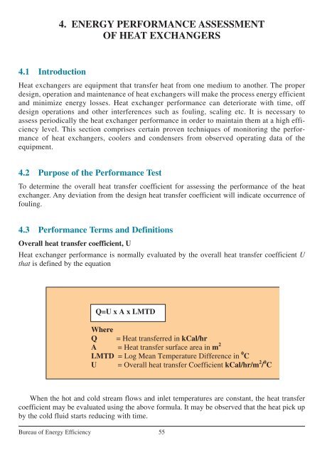
<strong>4.</strong>1 Introduction<br />
Heat <strong>exchangers</strong> are equipment that transfer <strong>heat</strong> from one medium to another. The proper<br />
design, operation and maintenance <strong>of</strong> <strong>heat</strong> <strong>exchangers</strong> will make the process <strong>energy</strong> efficient<br />
and minimize <strong>energy</strong> losses. Heat exchanger <strong>performance</strong> can deteriorate with time, <strong>of</strong>f<br />
design operations and other interferences such as fouling, scaling etc. It is necessary to<br />
assess periodically the <strong>heat</strong> exchanger <strong>performance</strong> in order to maintain them at a high efficiency<br />
level. This section comprises certain proven techniques <strong>of</strong> monitoring the <strong>performance</strong><br />
<strong>of</strong> <strong>heat</strong> <strong>exchangers</strong>, coolers and condensers from observed operating data <strong>of</strong> the<br />
equipment.<br />
<strong>4.</strong>2 Purpose <strong>of</strong> the Performance Test<br />
To determine the overall <strong>heat</strong> transfer coefficient for assessing the <strong>performance</strong> <strong>of</strong> the <strong>heat</strong><br />
exchanger. Any deviation from the design <strong>heat</strong> transfer coefficient will indicate occurrence <strong>of</strong><br />
fouling.<br />
<strong>4.</strong>3 Performance Terms and Definitions<br />
Overall <strong>heat</strong> transfer coefficient, U<br />
Heat exchanger <strong>performance</strong> is normally evaluated by the overall <strong>heat</strong> transfer coefficient U<br />
that is defined by the equation<br />
When the hot and cold stream flows and inlet temperatures are constant, the <strong>heat</strong> transfer<br />
coefficient may be evaluated using the above formula. It may be observed that the <strong>heat</strong> pick up<br />
by the cold fluid starts reducing with time.<br />
<strong>Bureau</strong> <strong>of</strong> Energy Efficiency<br />
55
Nomenclature<br />
A typical <strong>heat</strong> exchanger is shown in figure <strong>4.</strong>1 with nomenclature.<br />
<strong>4.</strong> Energy Performance Assessment Of Heat Exchangers<br />
Heat duty <strong>of</strong> the exchanger can be calculated either on the hot side fluid or cold side fluid<br />
as given below.<br />
Heat Duty for Hot fluid, Q h = W x C ph x (T i –T o ) ………..Eqn–1,<br />
Heat Duty for Cold fluid, Q c = wx C pc x ( t o –t i ) ………...Eqn–2<br />
If the operating <strong>heat</strong> duty is less than design <strong>heat</strong> duty, it may be due to <strong>heat</strong> losses, fouling<br />
in tubes, reduced flow rate (hot or cold) etc. Hence, for simple <strong>performance</strong> monitoring <strong>of</strong><br />
exchanger, efficiency may be considered as factor <strong>of</strong> <strong>performance</strong> irrespective <strong>of</strong> other parameter.<br />
However, in industrial practice, fouling factor method is more predominantly used.<br />
<strong>4.</strong>4 Methodology <strong>of</strong> Heat Exchanger Performance Assessment<br />
<strong>4.</strong><strong>4.</strong>1 Procedure for determination <strong>of</strong> Overall <strong>heat</strong> transfer Coefficient, U at field<br />
This is a fairly rigorous method <strong>of</strong> monitoring the <strong>heat</strong> exchanger <strong>performance</strong> by calculating<br />
the overall <strong>heat</strong> transfer coefficient periodically. Technical records are to be maintained for all<br />
the <strong>exchangers</strong>, so that problems associated with reduced efficiency and <strong>heat</strong> transfer can be<br />
identified easily. The record should basically contain historical <strong>heat</strong> transfer coefficient data<br />
versus time / date <strong>of</strong> observation. A plot <strong>of</strong> <strong>heat</strong> transfer coefficient versus time permits rational<br />
planning <strong>of</strong> an exchanger-cleaning program.<br />
The <strong>heat</strong> transfer coefficient is calculated by the equation<br />
U = Q / (A x LMTD)<br />
Where Q is the <strong>heat</strong> duty, A is the <strong>heat</strong> transfer area <strong>of</strong> the exchanger and LMTD is temperature<br />
driving force.<br />
The step by step procedure for determination <strong>of</strong> Overall <strong>heat</strong> transfer Coefficient are<br />
described below<br />
<strong>Bureau</strong> <strong>of</strong> Energy Efficiency<br />
56
<strong>4.</strong> Energy Performance Assessment Of Heat Exchangers<br />
Density and viscosity can be determined by analysis <strong>of</strong> the samples taken from the flow<br />
stream at the recorded temperature in the plant laboratory. Thermal conductivity and specific<br />
<strong>heat</strong> capacity if not determined from the samples can be collected from handbooks.<br />
<strong>Bureau</strong> <strong>of</strong> Energy Efficiency<br />
57
<strong>4.</strong> Energy Performance Assessment Of Heat Exchangers<br />
<strong>Bureau</strong> <strong>of</strong> Energy Efficiency<br />
58
<strong>4.</strong> Energy Performance Assessment Of Heat Exchangers<br />
<strong>4.</strong><strong>4.</strong>2 Examples<br />
a. Liquid - Liquid Exchanger<br />
A shell and tube exchanger <strong>of</strong> following configuration is considered being used for oil cooler<br />
with oil at the shell side and cooling water at the tube side.<br />
Tube Side<br />
• 460 Nos x 25.4mmOD x 2.11mm thick x 7211mm long<br />
• Pitch - 31.75mm 30° triangular<br />
• 2 Pass<br />
Shell Side<br />
• 787 mm ID<br />
• Baffle space - 787 mm<br />
• 1 Pass<br />
<strong>Bureau</strong> <strong>of</strong> Energy Efficiency<br />
59
<strong>4.</strong> Energy Performance Assessment Of Heat Exchangers<br />
<strong>Bureau</strong> <strong>of</strong> Energy Efficiency<br />
60
<strong>4.</strong> Energy Performance Assessment Of Heat Exchangers<br />
<strong>Bureau</strong> <strong>of</strong> Energy Efficiency<br />
61
Heat Duty: Actual duty differences will be practically negligible as these duty differences<br />
could be because <strong>of</strong> the specific <strong>heat</strong> capacity deviation with the temperature. Also, there could<br />
be some <strong>heat</strong> loss due to radiation from the hot shell side.<br />
Pressure drop: Also, the pressure drop in the shell side <strong>of</strong> the hot fluid is reported normal<br />
(only slightly less than the design figure). This is attributed with the increased average bulk<br />
temperature <strong>of</strong> the hot side due to decreased <strong>performance</strong> <strong>of</strong> the exchanger.<br />
Temperature range: As seen from the data the deviation in the temperature ranges could be<br />
due to the increased fouling in the tubes (cold stream), since a higher pressure drop is noticed.<br />
Heat Transfer coefficient: The estimated value has decreased due to increased fouling that has<br />
resulted in minimized active area <strong>of</strong> <strong>heat</strong> transfer.<br />
Physical properties: If available from the data or Lab analysis can be used for verification<br />
with the design data sheet as a cross check towards design considerations.<br />
Troubleshooting: Fouled exchanger needs cleaning.<br />
b. Surface Condenser<br />
A shell and tube exchanger <strong>of</strong> following configuration is considered being used for Condensing<br />
turbine exhaust steam with cooling water at the tube side.<br />
Tube Side<br />
20648 Nos x 25.4mmOD x 1.22mm thk x 18300mm long<br />
Pitch - 31.75mm 60° triangular<br />
1 Pass<br />
The monitored parameters are as below:<br />
<strong>4.</strong> Energy Performance Assessment Of Heat Exchangers<br />
Parameters Units Inlet Outlet<br />
Hot fluid flow, W kg/h 939888 939888<br />
Cold fluid flow, w kg/h 55584000 55584000<br />
Hot fluid Temp, T °C No data 3<strong>4.</strong>9<br />
Cold fluid Temp, t °C 18 27<br />
Hot fluid Pressure, P m Bar g 52.3 mbar 48.3<br />
Cold fluid Pressure, p Bar g 4 3.6<br />
Calculation <strong>of</strong> Thermal data:<br />
Area = 27871 m 2<br />
1. Duty:<br />
Q = q S + q L<br />
Hot fluid, Q = 576990 kW<br />
Cold Fluid, Q = 581825.5 kW<br />
<strong>Bureau</strong> <strong>of</strong> Energy Efficiency<br />
62
2. Hot Fluid Pressure Drop<br />
Pressure Drop = P i – P o = 52.3 – 48.3 = <strong>4.</strong>0 mbar.<br />
3. Cold Fluid Pressure Drop<br />
Pressure Drop = p i – p o = 4 – 3.6 = 0.4 bar.<br />
<strong>4.</strong> Temperature range hot fluid<br />
Temperature Range ∆T = T i – T o = No data<br />
5. Temperature Range Cold Fluid<br />
Temperature Range ∆t = t i – t o = 27 – 18 = 9 °C.<br />
6. Capacity Ratio<br />
Capacity ratio, R = Not significant in evaluation here.<br />
7. Effectiveness<br />
Effectiveness, S = (t o – t i ) / (T i – t i ) = Not significant in evaluation here.<br />
8. LMTD<br />
Calculated considering condensing part only<br />
a). LMTD, Counter Flow = ((3<strong>4.</strong>9 – 18)–(3<strong>4.</strong>9–27))/ ln ((3<strong>4.</strong>9–18)/(3<strong>4.</strong>9–27))<br />
= 11.8 deg C.<br />
b). Correction Factor to account for Cross flow<br />
F = 1.0.<br />
9. Corrected LMTD<br />
MTD = F x LMTD = 1.0 x 11.8 = 11.8 deg C.<br />
10. Heat Transfer Co-efficient<br />
Overall HTC, U = Q/ A ∆T = 576990/ (27871 x 11.8) = 1.75 kW/m 2 . K<br />
Comparison <strong>of</strong> Calculated data with Design Data<br />
<strong>4.</strong> Energy Performance Assessment Of Heat Exchangers<br />
Parameters Units Test Data Design Data<br />
Duty, Q kW 576990 588430<br />
Hot fluid side pressure drop, ∆P h mBar 4 mbar 3.7 mbar<br />
Cold fluid side pressure drop, ∆Pc Bar 0.4<br />
Temperature Range hot fluid, ∆T °C<br />
Temperature Range cold fluid, ∆t °C (27–18) = 9 (28–19) = 9<br />
Capacity ratio, R -----<br />
Effectiveness, S -----<br />
Corrected LMTD, MTD °C 11.8 8.9<br />
Heat Transfer Coefficient, U kW/(m 2 . K) 1.75 2.37<br />
<strong>Bureau</strong> <strong>of</strong> Energy Efficiency<br />
63
<strong>4.</strong> Energy Performance Assessment Of Heat Exchangers<br />
Heat Duty: Actual duty differences will be practically negligible as these duty differences<br />
could be because <strong>of</strong> the specific <strong>heat</strong> capacity deviation with the temperature. Also, there could<br />
be some <strong>heat</strong> loss due to radiation from the hot shell side.<br />
Pressure drop: The condensing side operating pressure raised due to the backpressure<br />
caused by the non-condensable. This has resulted in increased pressure drop across the steam<br />
side<br />
Temperature range: With reference to cooling waterside there is no difference in the range<br />
however, the terminal temperature differences has increased indicating lack <strong>of</strong> proper <strong>heat</strong><br />
transfer.<br />
Heat Transfer coefficient: Heat transfer coefficient has decreased due to increased amount <strong>of</strong><br />
non-condensable with the steam.<br />
Trouble shooting: Operations may be checked for tightness <strong>of</strong> the circuit and ensure<br />
proper venting <strong>of</strong> the system. The vacuum source might be verified for proper<br />
functioning.<br />
C. Vaporizer<br />
A shell and tube exchanger <strong>of</strong> following configuration is considered being used for vaporizing<br />
chlorine with steam at the shell side.<br />
Tube Side<br />
200 Nos x 25.4mmOD x 1.22mm thick x 6000mm long<br />
Pitch - 31.75mm 30° triangular<br />
2 Pass<br />
Area = 95.7.m 2<br />
<strong>Bureau</strong> <strong>of</strong> Energy Efficiency<br />
64
<strong>4.</strong> Energy Performance Assessment Of Heat Exchangers<br />
The monitored parameters are as below:<br />
Parameters Units Inlet Outlet<br />
Hot fluid flow, W kg/h 5015 5015<br />
Cold fluid flow, w kg/h 43500 43500<br />
Hot fluid Temp, T °C 108 108<br />
Cold fluid Temp, t °C 30 34<br />
Hot fluid Pressure, P Bar g 0.4 0.3<br />
Cold fluid Pressure, p Bar g 9 8.8<br />
Calculation <strong>of</strong> Thermal data:<br />
1. Duty:<br />
Q = q S + q L<br />
Hot fluid, Q = 3130 kW<br />
Cold Fluid, Q = q S + q L = 180.3 kW + 2948 kW = 3128.3 kW<br />
2. Hot Fluid Pressure Drop<br />
Pressure Drop = P i – P o = 0.4 – 0.3 = 0.1 bar<br />
3. Cold Fluid Pressure Drop<br />
Pressure Drop = p i – p o = 9 – 8.8 = 0.2 bar.<br />
<strong>4.</strong> Temperature range hot fluid<br />
Temperature Range ∆T = T i – T o = 0 °C<br />
5. Temperature Range Cold Fluid<br />
Temperature Range ∆t = t i – t o = 34 – 30 = 4 °C.<br />
6. Capacity Ratio<br />
Capacity ratio, R = Not significant in evaluation here.<br />
7. Effectiveness<br />
Effectiveness, S = (t o – t i ) / (T i – t i ) = Not significant in evaluation here.<br />
8. LMTD<br />
Calculated considering condensing part only<br />
a). LMTD, Counter Flow =((108 – 30)–(108–34))/ ln ((108–30)/(108–34)) = 76 °C.<br />
b). Correction Factor to account for Cross flow<br />
F = 1.0.<br />
9. Corrected LMTD<br />
MTD = F x LMTD = 1.0 x 76 = 76 °C.<br />
10. Heat Transfer Co-efficient<br />
Overall HTC, U = Q/ A ∆T = 3130/ (95.7 x 76) = 0.43 kW/m 2 . K<br />
<strong>Bureau</strong> <strong>of</strong> Energy Efficiency<br />
65
<strong>4.</strong> Energy Performance Assessment Of Heat Exchangers<br />
Comparison <strong>of</strong> Calculated data with Design Data<br />
Parameters Units Test Data Design Data<br />
Duty, Q kW 3130 3130<br />
Hot fluid side pressure drop, ∆P h Bar 0.1 Neg<br />
Cold fluid side pressure drop, ∆P c Bar 0.2<br />
Temperature Range hot fluid, ∆T °C<br />
Temperature Range cold fluid, ∆t °C 4 4<br />
Capacity ratio, R -----<br />
Effectiveness, S -----<br />
Corrected LMTD, MTD °C 76<br />
Heat Transfer Coefficient, U kW/(m 2 . K) 0.42 0.44<br />
Heat Duty: There is no difference inferred from the duty as the exchanger is performing as per<br />
the requirement<br />
Pressure drop: The steam side pressure drop has increased in spite <strong>of</strong> condensation at the<br />
steam side. Indication <strong>of</strong> non-condensable presence in steam side<br />
Temperature range: No deviations<br />
Heat Transfer coefficient: Even at no deviation in the temperature pr<strong>of</strong>ile at the chlorine side,<br />
<strong>heat</strong> transfer coefficient has decreased with an indication <strong>of</strong> overpressure at the shell side. This<br />
indicates disturbances to the condensation <strong>of</strong> steam at the shell side. Non-condensable suspected<br />
at steam side.<br />
Trouble shooting: Operations may be checked for presence <strong>of</strong> chlorine at the shell side<br />
through tube leakages. Observing the steam side vent could do this. Alternately condensate pH<br />
could be tested for presence <strong>of</strong> acidity.<br />
<strong>Bureau</strong> <strong>of</strong> Energy Efficiency<br />
66
<strong>4.</strong> Energy Performance Assessment Of Heat Exchangers<br />
d. Air <strong>heat</strong>er<br />
A finned tube exchanger <strong>of</strong> following configuration is considered being used for <strong>heat</strong>ing air<br />
with steam in the tube side.<br />
The monitored parameters are as below:<br />
Parameters Units Inlet Outlet<br />
Hot fluid flow, W kg/h 3000 3000<br />
Cold fluid flow, w kg/h 92300 92300<br />
Hot fluid Temp, T °C 150 150<br />
Cold fluid Temp, t °C 30 95<br />
Hot fluid Pressure, P Bar g<br />
Cold fluid Pressure, p mBar g 200 mbar 180 mbar<br />
Calculation <strong>of</strong> Thermal data:<br />
Bare tube Area = 42.8 m 2 ; Fined tube area = 856 m 2<br />
1.Duty:<br />
Hot fluid, Q = 1748 kW<br />
Cold Fluid, Q = 1726 kW<br />
2. Hot Fluid Pressure Drop<br />
Pressure Drop = P i – P o = Neg<br />
3. Cold Fluid Pressure Drop<br />
Pressure Drop = p i – p o = 200–180 = 20 mbar.<br />
<strong>4.</strong> Temperature range hot fluid<br />
Temperature Range ∆T = T i – T o = Not required.<br />
5. Temperature Range Cold Fluid<br />
Temperature Range ∆t = t i – t o = 95 – 30 = 65 °C.<br />
6. Capacity Ratio<br />
Capacity ratio, R = Not significant in evaluation here.<br />
7. Effectiveness<br />
Effectiveness, S = (t o – t i ) / (T i – t i ) = Not significant in evaluation here.<br />
8. LMTD<br />
Calculated considering condensing part only<br />
a). LMTD, Counter Flow =((150 – 30)–(150–95)/ ln ((150–30)/(150–95)) = 83.3 °C.<br />
b). Correction Factor to account for cross flow<br />
F = 0.95<br />
9. Corrected LMTD<br />
MTD = F x LMTD = 0.95 x 83.3 = 79 °C.<br />
10. Overall Heat Transfer Co-efficient (HTC)<br />
U = Q/ A ∆T = 1748/ (856 x 79) = 0.026 kW/m 2 . K<br />
<strong>Bureau</strong> <strong>of</strong> Energy Efficiency<br />
67
Comparison <strong>of</strong> Calculated data with Design Data<br />
<strong>4.</strong> Energy Performance Assessment Of Heat Exchangers<br />
Parameters Units Test Data Design Data<br />
Duty, Q kW 1748 1800<br />
Hot fluid side pressure drop, ∆P h Bar Neg Neg<br />
Cold fluid side pressure drop, ∆P c Bar 20 15<br />
Temperature Range hot fluid, ∆T °C<br />
Temperature Range cold fluid, ∆t °C 65 65<br />
Capacity ratio, R -----<br />
Effectiveness, S -----<br />
Corrected LMTD, MTD °C 79 79<br />
Heat Transfer Coefficient, U kW/(m 2 . K) 0.026 0.03<br />
Heat Duty: The difference inferred from the duty as the exchanger is under performing than<br />
required<br />
Pressure drop: The airside pressure drop has increased in spite <strong>of</strong> condensation at the steam<br />
side. Indication <strong>of</strong> choking and dirt blocking at the airside.<br />
Temperature range: No deviations<br />
Heat Transfer coefficient: Decreased because <strong>of</strong> decreased fin efficiency due to choking on<br />
air side.<br />
Trouble shooting: Operations may be checked to perform pulsejet cleaning with steam / blow<br />
air jet on air side if the facility is available. Mechanical cleaning may have to be planned during<br />
any down time in the immediate future.<br />
<strong>Bureau</strong> <strong>of</strong> Energy Efficiency<br />
68
<strong>4.</strong><strong>4.</strong>3 Instruments for monitoring:<br />
<strong>4.</strong> Energy Performance Assessment Of Heat Exchangers<br />
The test and evaluation <strong>of</strong> the <strong>performance</strong> <strong>of</strong> the <strong>heat</strong> exchanger equipment is carried out by<br />
measurement <strong>of</strong> operating parameters upstream and downstream <strong>of</strong> the exchanger. Due care<br />
needs to be taken to ensure the accuracy and correctness <strong>of</strong> the measured parameter. The instruments<br />
used for measurements require calibration and verification prior to measurement.<br />
Parameters Units Instruments used<br />
Fluid flow kg/h Flow can be measured with instruments like<br />
Orifice flow meter, Vortex flow meter, Venturi<br />
meters, Coriollis flow meters, Magnetic flow<br />
meter<br />
as applicable to the fluid service and flow ranges<br />
Temperature °C Thermo gauge for low ranges, RTD, etc.<br />
Pressure Bar g Liquid manometers, Draft gauge, Pressure<br />
gauges Bourdon and diaphragm type, Absolute<br />
pressure transmitters, etc.<br />
Density kg/m 3 Measured in the Laboratory as per ASTM<br />
standards, hydrometer, etc<br />
Viscosity MpaS Measured in the Laboratory as per ASTM<br />
standards, viscometer, etc.<br />
Specific <strong>heat</strong> capacity J/(kg.K) Measured in the Laboratory as per ASTM<br />
standards<br />
Thermal conductivity W/(m.K) Measured in the Laboratory as per ASTM<br />
standards<br />
Composition+ %wt (or) % Vol Measured in the Laboratory as per ASTM<br />
standards using Chemical analysis, HPLC, GC,<br />
Spectrophotometer, etc.<br />
<strong>4.</strong><strong>4.</strong>4 Terminology used in Heat Exchangers<br />
Terminology Definition Unit<br />
Capacity ratio Ratio <strong>of</strong> the products <strong>of</strong> mass flow rate and specific<br />
<strong>heat</strong> capacity <strong>of</strong> the cold fluid to that <strong>of</strong> the hot fluid.<br />
Also computed by the ratio <strong>of</strong> temperature range <strong>of</strong> the<br />
hot fluid to that <strong>of</strong> the cold fluid.<br />
Higher the ratio greater will be size <strong>of</strong> the exchanger<br />
Co current flow An exchanger wherein the fluid flow direction <strong>of</strong> the<br />
exchanger cold and hot fluids are same<br />
Counter flow Exchangers wherein the fluid flow direction <strong>of</strong> the cold and<br />
exchanger hot fluids are opposite. Normally preferred<br />
Cross flow An exchanger wherein the fluid flow direction <strong>of</strong> the<br />
cold and hot fluids are in cross<br />
<strong>Bureau</strong> <strong>of</strong> Energy Efficiency<br />
69
Density It is the mass per unit volume <strong>of</strong> a material kg/m 3<br />
Effectiveness<br />
Fouling<br />
Fouling Factor<br />
Heat Duty<br />
Heat exchanger<br />
Heat Flux<br />
Heat transfer<br />
Heat transfer<br />
surface or <strong>heat</strong><br />
Transfer area<br />
Individual<br />
Heat transfer<br />
Coefficient<br />
<strong>4.</strong> Energy Performance Assessment Of Heat Exchangers<br />
Ratio <strong>of</strong> the cold fluid temperature range to that <strong>of</strong><br />
the inlet temperature difference <strong>of</strong> the hot and<br />
cold fluid. Higher the ratio lesser will be requirement<br />
<strong>of</strong> <strong>heat</strong> transfer surface<br />
The phenomenon <strong>of</strong> formation and development <strong>of</strong><br />
scales and deposits over the <strong>heat</strong> transfer surface<br />
diminishing the <strong>heat</strong> flux. The process <strong>of</strong> fouling will<br />
get indicated by the increase in pressure drop<br />
The reciprocal <strong>of</strong> <strong>heat</strong> transfer coefficient <strong>of</strong> the<br />
dirt formed in the <strong>heat</strong> exchange process.<br />
Higher the factor lesser will be the overall <strong>heat</strong><br />
transfer coefficient.<br />
(m 2 .K)/W<br />
The capacity <strong>of</strong> the <strong>heat</strong> exchanger equipment<br />
expressed in terms <strong>of</strong> <strong>heat</strong> transfer rate, viz.<br />
magnitude <strong>of</strong> <strong>energy</strong> or <strong>heat</strong> transferred per time.<br />
It means the exchanger is capable <strong>of</strong> performing at<br />
this capacity in the given system<br />
W<br />
Refers to the nomenclature <strong>of</strong> equipment designed<br />
and constructed to transmit <strong>heat</strong> content<br />
(enthalpy or <strong>energy</strong>) <strong>of</strong> a comparatively high<br />
temperature hot fluid to a lower temperature cold<br />
fluid wherein the temperature <strong>of</strong> the hot fluid<br />
decreases (or remain constant in case <strong>of</strong> losing latent<br />
<strong>heat</strong> <strong>of</strong> condensation) and the temperature <strong>of</strong> the cold<br />
fluid increases (or remain constant in case <strong>of</strong> gaining<br />
latent <strong>heat</strong> <strong>of</strong> vaporisation). A <strong>heat</strong> exchanger will<br />
normally provide indirect contact <strong>heat</strong>ing. E.g. A<br />
cooling tower cannot be called a <strong>heat</strong> exchanger<br />
where water is cooled by direct contact with air<br />
The rate <strong>of</strong> <strong>heat</strong> transfer per unit surface <strong>of</strong> a <strong>heat</strong><br />
exchanger W/ m 2<br />
The process <strong>of</strong> transport <strong>of</strong> <strong>heat</strong> <strong>energy</strong> from a<br />
hot source to the comparatively cold surrounding<br />
Refers to the surface area <strong>of</strong> the <strong>heat</strong> exchanger that<br />
provides the indirect contact between the hot and cold<br />
fluid in effecting the <strong>heat</strong> transfer. Thus the <strong>heat</strong> transfer<br />
area is defined as the surface having both sides<br />
wetted with one side by the hot fluid and the other<br />
side by the cold fluid providing indirect contact for<br />
<strong>heat</strong> transfer m 2<br />
The <strong>heat</strong> flux per unit temperature difference across<br />
boundary layer <strong>of</strong> the hot / cold fluid film formed<br />
at the <strong>heat</strong> transfer surface. The magnitude <strong>of</strong> <strong>heat</strong><br />
transfer coefficient indicates the ability <strong>of</strong> <strong>heat</strong><br />
conductivity <strong>of</strong> the given fluid. It increases with increase<br />
in density, velocity, specific <strong>heat</strong>, geometry <strong>of</strong> the film<br />
forming surface<br />
W/( m 2 .K)<br />
<strong>Bureau</strong> <strong>of</strong> Energy Efficiency<br />
70
LMTD Calculated considering the Capacity and effectiveness<br />
Correction <strong>of</strong> a <strong>heat</strong> exchanging process. When multiplied with<br />
factor<br />
LMTD gives the corrected LMTD thus accounting<br />
for the temperature driving force for the cross flow<br />
pattern as applicable inside the exchanger<br />
Logarithmic The logarithmic average <strong>of</strong> the terminal temperature<br />
Mean<br />
approaches across a <strong>heat</strong> exchanger<br />
Temperature<br />
difference,<br />
LMTD °C<br />
Overall Heat The ratio <strong>of</strong> <strong>heat</strong> flux per unit difference in approach<br />
transfer<br />
Coefficient<br />
<strong>4.</strong> Energy Performance Assessment Of Heat Exchangers<br />
across a <strong>heat</strong> exchange equipment considering the<br />
individual coefficient and <strong>heat</strong> exchanger metal surface<br />
conductivity. The magnitude indicates the ability <strong>of</strong><br />
<strong>heat</strong> transfer for a given surface. Higher the coefficient<br />
lesser will be the <strong>heat</strong> transfer surface requirement<br />
W/(m 2 .K)<br />
Pressure drop The difference in pressure between the inlet and<br />
outlet <strong>of</strong> a <strong>heat</strong> exchanger<br />
Bar<br />
Specific The <strong>heat</strong> content per unit weight <strong>of</strong> any material per<br />
<strong>heat</strong> capacity degree raise/fall in temperature J/(kg.K)<br />
Temperature The difference in the temperature between the hot and<br />
Approach cold fluids at the inlet / outlet <strong>of</strong> the <strong>heat</strong> exchanger.<br />
The greater the difference greater will be <strong>heat</strong><br />
transfer flux °C<br />
Temperature The difference in the temperature between the inlet<br />
Range and outlet <strong>of</strong> a hot/cold fluid in a <strong>heat</strong> exchanger °C<br />
Terminal The temperatures at the inlet / outlet <strong>of</strong> the hot / cold<br />
temperature fluid steams across a <strong>heat</strong> exchanger °C<br />
Thermal The rate <strong>of</strong> <strong>heat</strong> transfer by conduction though any<br />
Conductivity substance across a distance per unit<br />
temperature difference<br />
W/(m 2 .K)<br />
Viscosity The force on unit volume <strong>of</strong> any material that<br />
will cause per velocity<br />
Pa<br />
<strong>Bureau</strong> <strong>of</strong> Energy Efficiency<br />
71
<strong>4.</strong> Energy Performance Assessment Of Heat Exchangers<br />
1. What is meant by LMTD ?<br />
QUESTIONS<br />
2. Distinguish between <strong>heat</strong> exchanger efficiency and effectiveness.<br />
3. Explain the terms <strong>heat</strong> duty and capacity ratio.<br />
<strong>4.</strong> What is meant by fouling?<br />
5. List five <strong>heat</strong> <strong>exchangers</strong> used in industrial practice.<br />
6. What are the parameters, which are to be monitored for the <strong>performance</strong> <strong>assessment</strong><br />
<strong>of</strong> <strong>heat</strong> <strong>exchangers</strong>?<br />
7. In a <strong>heat</strong> exchanger the hot stream enters at 70°C and leaves at 55°C. On the other<br />
side the cold stream enters at 30°C and leaves at 55°C. Find out the LMTD <strong>of</strong> the<br />
<strong>heat</strong> exchanger.<br />
8. In a condenser what type <strong>of</strong> <strong>heat</strong>s are considered in estimating the <strong>heat</strong> duty?<br />
a) Latent Heat b) Sensible <strong>heat</strong> c) Specific <strong>heat</strong> d) Latent <strong>heat</strong> and sensible <strong>heat</strong><br />
9. What is the need for <strong>performance</strong> <strong>assessment</strong> <strong>of</strong> a <strong>heat</strong> exchanger?<br />
10. The unit <strong>of</strong> overall coefficient <strong>of</strong> <strong>heat</strong> transfer is<br />
a) kCal/hr/m 2 °C b) kCal/kg °C c) kCal/m 2 hr d) kCal/hg m 2<br />
REFERENCES<br />
1. "Process Heat Transfer" by D.Q.Kern, Edn. 1965.<br />
2. "Modern Power Station Practice" - British Electricity International- Volume - G;<br />
Chapter - 7 - " Plant <strong>performance</strong> and <strong>performance</strong> monitoring.<br />
3. Coulsons & Richardson's CHEMICAL ENGINEERING Volume 3 third edition<br />
<strong>4.</strong> Scimod " Scientific Modeling S<strong>of</strong>tware", techno s<strong>of</strong>tware International, India<br />
5. Ganapathy. V, "Fouling factor estimated quickly", O&G Journal, Aug 1992.<br />
6. Liberman, Norman P, Trouble shooting Process Operations, Penwell Books, Tulsa,<br />
Oklahoma<br />
<strong>Bureau</strong> <strong>of</strong> Energy Efficiency<br />
72