FLP-B+C MAXI VS
FLP-B+C MAXI VS
FLP-B+C MAXI VS

Create successful ePaper yourself
Turn your PDF publications into a flip-book with our unique Google optimized e-Paper software.
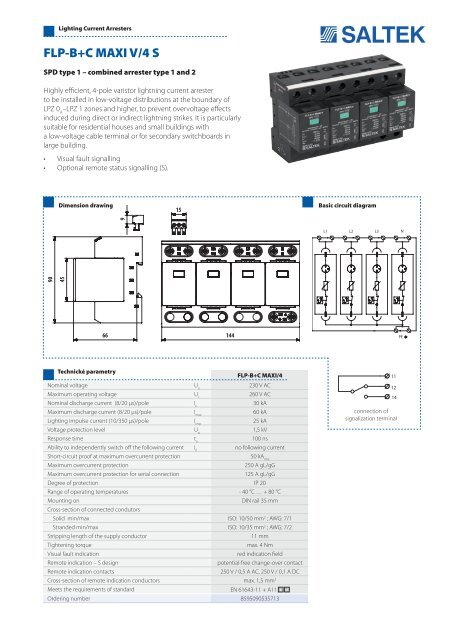
Lighting Current Arresters<br />
<strong>FLP</strong>-<strong>B+C</strong> <strong>MAXI</strong> V/4 S<br />
SPD type 1 – combined arrester type 1 and 2<br />
Highly efficient, 4-pole varistor lightning current arrester<br />
to be installed in low-voltage distributions at the boundary of<br />
LPZ 0 A<br />
–LPZ 1 zones and higher, to prevent overvoltage effects<br />
induced during direct or indirect lightning strikes. It is particularly<br />
suitable for residential houses and small buildings with<br />
a low-voltage cable terminal or for secondary switchboards in<br />
large building.<br />
• Visual fault signalling<br />
• Optional remote status signalling (S).<br />
Dimension drawing<br />
15<br />
15<br />
Basic circuit diagram<br />
90<br />
45<br />
90<br />
45<br />
9<br />
9<br />
66<br />
66<br />
144<br />
144<br />
Technické parametry<br />
<strong>FLP</strong>-<strong>B+C</strong> <strong>MAXI</strong>/4<br />
Nominal voltage U n<br />
230 V AC<br />
Maximum operating voltage U c<br />
260 V AC<br />
Nominal discharge current (8/20 μs)/pole I n<br />
30 kA<br />
Maximum discharge current (8/20 μs)/pole I max<br />
60 kA<br />
Lighting impulse current (10/350 μs)/pole I imp<br />
25 kA<br />
Voltage protection level U p<br />
1,5 kV<br />
Response time t a<br />
100 ns<br />
Ability to independently switch off the following current I fi<br />
no following current<br />
Short-circuit proof at maximum overcurrent protection<br />
50 kA rms<br />
Maximum overcurrent protection<br />
250 A gL/gG<br />
Maximum overcurrent protection for serial connection<br />
125 A gL/gG<br />
Degree of protection IP 20<br />
Range of operating temperatures - 40 °C … + 80 °C<br />
Mounting on<br />
DIN rail 35 mm<br />
Cross-section of connected condutors<br />
Solid min/max ISO: 10/50 mm 2 ; AWG: 7/1<br />
Stranded min/max ISO: 10/35 mm 2 ; AWG: 7/2<br />
Stripping length of the supply conductor<br />
11 mm<br />
Tightening torque<br />
max. 4 Nm<br />
Visual fault indication<br />
red indication field<br />
Remote indication – S design<br />
potential-free change-over contact<br />
Remote indication contacts<br />
250 V / 0,5 A AC, 250 V / 0,1 A DC<br />
Cross-section of remote indication conductors max. 1,5 mm 2<br />
Meets the requirements of standard<br />
EN 61643-11 + A11<br />
Ordering number 8595090535713<br />
connection of<br />
signalization terminal