FLP-B+C MAXI VS
FLP-B+C MAXI VS
FLP-B+C MAXI VS

Create successful ePaper yourself
Turn your PDF publications into a flip-book with our unique Google optimized e-Paper software.
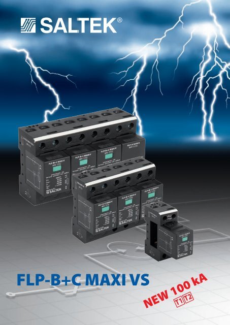
<strong>FLP</strong>-<strong>B+C</strong> <strong>MAXI</strong> <strong>VS</strong><br />
NEW 100 kA<br />
T1 T2
Lighting Current Arresters<br />
<strong>FLP</strong>-<strong>B+C</strong> <strong>MAXI</strong> <strong>VS</strong><br />
SPD type 1 – combined arrester type 1 and 2<br />
Surge protector devices (SPD) of class <strong>B+C</strong> serve for protection of low-voltage<br />
(230/400 V AC) networks and connected appliances against surge voltages due to<br />
direct - and indirect lightning strikes.<br />
The <strong>FLP</strong>-<strong>B+C</strong> <strong>MAXI</strong> SPD is built in a single block.<br />
Module offers a combination of heavy duty gas discharge tube (GDT) rated at 25 kA<br />
(10/350 µsec pulse) with high energy varistors block. This module guarantee no<br />
follow-on current, very low leakage current (µA range) and very low residual voltage.<br />
The form a part of the protection of buildings and their accessories in the concept of<br />
zone lightning protection at the boundary of the LPZ 0 and LPZ 1 (or higher) zones.<br />
• reliable arrester disconnection during overload or damaging of the protective<br />
module by thermal and dynamical varistor disconnection<br />
• optical fault indication – changing color of the signaling flag from green to red<br />
• low voltage Up<br />
• housing material according to UL 94 V0<br />
• complies to IEC 61643-1:2005<br />
• UL 1449 ed.2 standard compliancy in request<br />
Dimension drawing<br />
15<br />
Basic circuit diagram<br />
90<br />
45<br />
9<br />
L/N ( )<br />
L/N ( )<br />
66<br />
(L/N)<br />
(L/N)<br />
36<br />
connection<br />
of signalization<br />
terminal<br />
Technical data<br />
<strong>FLP</strong>-<strong>B+C</strong> <strong>MAXI</strong> <strong>VS</strong><br />
Nominal voltage U n<br />
230 V AC<br />
Maximum operating voltage U c<br />
260 V AC<br />
Nominal discharge current (8/20 μs) I n<br />
30 kA<br />
Lightning impulse current (10/350 μs) I imp<br />
25 kA<br />
Maximum discharge current (8/20 μs) I max<br />
60 kA<br />
Voltage protection level U p<br />
1,5 kA<br />
Response time t a<br />
100 ns<br />
Ability to independently switch off the following current I fi<br />
no following current<br />
Short-circuit proof at maximum overcurrent protection<br />
50 kA rms<br />
Maximum overcurrent protection<br />
250 A gL/gG<br />
Maximum overcurrent protection for serial connection<br />
125 A gL/gG<br />
Degree of protection IP 20<br />
Range of operating temperatures - 40 °C … + 80 °C<br />
Mounting on<br />
DIN rail 35 mm<br />
Cross-section of connected conductors<br />
Solid min/max ISO: 10/50 mm 2 ; AWG: 7/1<br />
Stranded min/max ISO: 10/35 mm 2 ; AWG: 7/2<br />
Stripping length of the supply conductor<br />
14 mm<br />
Tightening torque<br />
max. 4 Nm<br />
Visual fault indication<br />
red indication field<br />
Remote indication – S design<br />
potential-free change-over contact<br />
Remote indication contacts<br />
250 V / 0,5 A AC, 250 V / 0,1 A DC<br />
Cross-section of remote indication conductors max. 1,5 mm 2<br />
Meets the requirements of standard<br />
EN 61643-11 + A11<br />
Ordering number 8595090535331
Lightning Current Arresters<br />
<strong>FLP</strong>-<strong>B+C</strong> <strong>MAXI</strong> V/3S<br />
SPD type 1 – combined arrester type 1 and 2<br />
Highly efficient varistor lightning current arrester to be installed<br />
in low-voltage distributions at the boundary of LPZ 0 A<br />
–LPZ 1<br />
zones and higher, to prevent overvoltage effects induced during<br />
direct or indirect lightning strikes. It is particularly suitable for<br />
residential houses and small buildings with<br />
a low-voltage cable terminal or for secondary switchboards<br />
in large building.<br />
• Visual fault signalling<br />
• Optional remote status signalling (S).<br />
Dimension drawing<br />
15<br />
Basic circuit diagram<br />
90<br />
45<br />
9<br />
66 108<br />
Technical data<br />
<strong>FLP</strong>-<strong>B+C</strong> <strong>MAXI</strong> V/3S<br />
Nominal voltage U n<br />
230 V AC<br />
Maximum operating voltage U c<br />
260 V AC<br />
Nominal discharge current (8/20 μs)/pole I n<br />
30 kA<br />
Maximum discharge current (8/20 μs)/pole I max<br />
60 kA<br />
Lightning impulse current (10/350 μs)/pole I imp<br />
25 kA<br />
Voltage protection level U p<br />
1,5 kV<br />
Response time t a<br />
100 ns<br />
Ability to independently switch off the following current I fi<br />
no following current<br />
Short-circuit proof at maximum overcurrent protection<br />
50 kA rms<br />
Maximum overcurrent protection<br />
250 A gL/gG<br />
Maximum overcurrent protection for serial connection<br />
125 A gL/gG<br />
Degree of protection IP 20<br />
Range of operating temperatures - 40 °C … + 80 °C<br />
Mounting on<br />
DIN rail 35 mm<br />
Cross-section of connected conductors<br />
Solid min/max ISO: 10/50 mm 2 ; AWG: 7/1<br />
Stranded min/max ISO: 10/35 mm 2 ; AWG: 7/2<br />
Stripping length of the supply conductor<br />
11 mm<br />
Tightening torque<br />
max. 4 Nm<br />
Visual fault indication<br />
red indication field<br />
Remote indication<br />
potential-free change-over contact<br />
Remote indication contacts<br />
250 V / 0,5 A AC, 250 V / 0,1 A DC<br />
Cross-section of remote indication conductors max. 1,5 mm 2<br />
Meets the requirements of standard<br />
EN 61643-11 + A11<br />
Ordering number 8595090535706<br />
connection of<br />
signalization terminal
Lighting Current Arresters<br />
<strong>FLP</strong>-<strong>B+C</strong> <strong>MAXI</strong> V/4 S<br />
SPD type 1 – combined arrester type 1 and 2<br />
Highly efficient, 4-pole varistor lightning current arrester<br />
to be installed in low-voltage distributions at the boundary of<br />
LPZ 0 A<br />
–LPZ 1 zones and higher, to prevent overvoltage effects<br />
induced during direct or indirect lightning strikes. It is particularly<br />
suitable for residential houses and small buildings with<br />
a low-voltage cable terminal or for secondary switchboards in<br />
large building.<br />
• Visual fault signalling<br />
• Optional remote status signalling (S).<br />
Dimension drawing<br />
15<br />
15<br />
Basic circuit diagram<br />
90<br />
45<br />
90<br />
45<br />
9<br />
9<br />
66<br />
66<br />
144<br />
144<br />
Technické parametry<br />
<strong>FLP</strong>-<strong>B+C</strong> <strong>MAXI</strong>/4<br />
Nominal voltage U n<br />
230 V AC<br />
Maximum operating voltage U c<br />
260 V AC<br />
Nominal discharge current (8/20 μs)/pole I n<br />
30 kA<br />
Maximum discharge current (8/20 μs)/pole I max<br />
60 kA<br />
Lighting impulse current (10/350 μs)/pole I imp<br />
25 kA<br />
Voltage protection level U p<br />
1,5 kV<br />
Response time t a<br />
100 ns<br />
Ability to independently switch off the following current I fi<br />
no following current<br />
Short-circuit proof at maximum overcurrent protection<br />
50 kA rms<br />
Maximum overcurrent protection<br />
250 A gL/gG<br />
Maximum overcurrent protection for serial connection<br />
125 A gL/gG<br />
Degree of protection IP 20<br />
Range of operating temperatures - 40 °C … + 80 °C<br />
Mounting on<br />
DIN rail 35 mm<br />
Cross-section of connected condutors<br />
Solid min/max ISO: 10/50 mm 2 ; AWG: 7/1<br />
Stranded min/max ISO: 10/35 mm 2 ; AWG: 7/2<br />
Stripping length of the supply conductor<br />
11 mm<br />
Tightening torque<br />
max. 4 Nm<br />
Visual fault indication<br />
red indication field<br />
Remote indication – S design<br />
potential-free change-over contact<br />
Remote indication contacts<br />
250 V / 0,5 A AC, 250 V / 0,1 A DC<br />
Cross-section of remote indication conductors max. 1,5 mm 2<br />
Meets the requirements of standard<br />
EN 61643-11 + A11<br />
Ordering number 8595090535713<br />
connection of<br />
signalization terminal
Lightning Current Arresters<br />
<strong>FLP</strong>-<strong>B+C</strong> <strong>MAXI</strong> V/3S+1<br />
SPD type 1 and type 2– combined arrester type 1 and 2<br />
Highly efficient varistor lightning current arrester to be installed<br />
in low-voltage distributions at the boundary of LPZ 0 A<br />
–LPZ 1<br />
zones and higher, to prevent overvoltage effects induced<br />
during direct or indirect lightning strikes. It is particularly<br />
suitable for residential houses and small buildings with<br />
a low-voltage cable terminal or for secondary switchboards<br />
in large building.<br />
• Visual fault signalling<br />
• Optional remote status signalling (S).<br />
Dimension drawing<br />
15<br />
15<br />
Basic circuit diagram<br />
90<br />
45<br />
90<br />
45<br />
9<br />
9<br />
66 66 144 144<br />
Technical data<br />
L-N<br />
N-PE<br />
Nominal voltage U n<br />
230 V AC —<br />
Maximum operating voltage U c<br />
260 V AC 255 V AC<br />
Nominal discharge current (8/20 μs)/pole I n<br />
30 kA 100 kA<br />
Maximum discharge current (8/20 μs) I max<br />
60 kA 100 kA<br />
Lighting impulse current (10/350 μs)/pole I imp<br />
25 kA 100 kA<br />
Voltage protection level U p<br />
1,5 kV 1,5 kV<br />
Response time t a<br />
100 ns 100 ns<br />
Ability to independently switch off the following current I fi<br />
no following current 100 A<br />
Short-circuit proof at maximum overcurrent protection 50 kA rms<br />
—<br />
Maximum overcurrent protection 250 A gL/gG —<br />
Maximum overcurrent protection for serial connection 125 A gL/gG —<br />
Degree of protection IP 20 IP 20<br />
Range of operating temperatures - 40 °C … + 80 °C - 40 °C … + 80 °C<br />
Mounting on DIN rail 35 mm DIN rail 35 mm<br />
Cross-section of connected condutors<br />
Solid min/max ISO: 10/50 mm 2 ; AWG: 7/1 ISO: 10/50 mm 2 ; AWG: 7/1<br />
Stranded min/max ISO: 10/35 mm 2 ; AWG: 7/2 ISO: 10/35 mm 2 ; AWG: 7/2<br />
Stripping length of the supply conductor 11 mm 11 mm<br />
Tightening torque max. 4 Nm max. 4 Nm<br />
Visual fault indication red indication field no<br />
Remote indication* potential-free change-over contact —<br />
Remote indication contacts 250 V / 0,5 A AC, 250 V / 0,1 A DC —<br />
Cross-section of remote indication conductors max. 1,5 mm 2 —<br />
Meets the requirements of standard EN 61643-11 + A11 EN 61643-11 + A11<br />
Ordering number 8595090535720<br />
* Remote signalling of N-PE module shows the presence of the replaceable module<br />
connection of<br />
signalization terminal
Lightning Current Arresters<br />
<strong>FLP</strong>-A50N <strong>VS</strong><br />
SPD type 1 – lightning current arrester<br />
N-PE module, replaceable module<br />
To be installed in low-voltage distributions at the boundary of<br />
LPZ 0 A<br />
–LPZ 1 zones and higher to prevent overvoltage effects<br />
induced during direct or indirect lightning strikes for the<br />
connection of SPD type 1 in the mode 1+1.<br />
Dimension drawing<br />
15<br />
Basic circuit diagram<br />
90<br />
45<br />
9<br />
N( )<br />
N( )<br />
(N)<br />
(N)<br />
66 36<br />
Technical data<br />
<strong>FLP</strong>-A50N V<br />
Nominal voltage U n<br />
—<br />
Maximum operating voltage U c<br />
255 V AC<br />
Nominal discharge current (8/20 μs) I n<br />
50 kA<br />
Maximum discharge current (8/20 μs) I max<br />
100 kA<br />
Lightning impulse current (10/350 μs) I imp<br />
50 kA<br />
Voltage protection level U p<br />
1,5 kV<br />
Response time t a<br />
100 ns<br />
Ability to independently switch off the following current I fi<br />
100 A<br />
Short-circuit proof at maximum overcurrent protection —<br />
Maximum overcurrent protection —<br />
Degree of protection IP 20<br />
Range of operating temperatures - 40 °C … + 80 °C<br />
Mounting on<br />
DIN rail 35 mm<br />
Cross-section of connected conductors<br />
Solid min/max ISO: 10/50 mm 2 ; AWG: 7/1<br />
Stranded min/max ISO: 10/35 mm 2 ; AWG: 7/2<br />
Stripping length of the supply conductor<br />
11 mm<br />
Tightening torque<br />
max. 4 Nm<br />
Visual fault indication<br />
no<br />
Remote indication *<br />
potential-free change-over contact<br />
Remote indication contacts<br />
250 V / 0,5 A AC, 250 V / 0,1 A DC<br />
Cross-section of remote indication conductors max. 1,5 mm 2<br />
Meets the requirements of standard<br />
EN 61643-11 + A11<br />
Ordering number 8595090535737<br />
* Remote signalling of N-PE module shows the presence of the replaceable module
Lightning Current Arresters<br />
<strong>FLP</strong>-A100N <strong>VS</strong><br />
SPD type 1 – lightning current arrester<br />
N-PE module, replaceable module<br />
To be installed in low-voltage distributions at the boundary of<br />
LPZ 0 A<br />
and LPZ 1 zones to prevent overvoltage effects induced<br />
during direct or indirect lightning strikes for the connection<br />
of SPD type 1 in the mode 3+1.<br />
Dimension drawing<br />
15<br />
Basic circuit diagram<br />
90<br />
45<br />
9<br />
N( )<br />
N( )<br />
(N)<br />
(N)<br />
66 36<br />
Technical data<br />
<strong>FLP</strong>-A100N V<br />
Nominal voltage U n<br />
—<br />
Maximum operating voltage U c<br />
255 V AC<br />
Nominal discharge current (8/20 μs)/pole I n<br />
100 kA<br />
Maximum discharge current (8/20 μs) I max<br />
100 kA<br />
Lighting impulse current (10/350 μs)/pole I imp<br />
100 kA<br />
Voltage protection level U p<br />
1,5 kV<br />
Response time t a<br />
100 ns<br />
Ability to independently switch off the following current I fi<br />
100 A<br />
Short-circuit proof at maximum overcurrent protection —<br />
Maximum overcurrent protection —<br />
Degree of protection IP 20<br />
Range of operating temperatures - 40 °C … + 80 °C<br />
Mounting on<br />
DIN rail 35 mm<br />
Cross-section of connected condutors<br />
Solid min/max ISO: 10/50 mm 2 ; AWG: 7/1<br />
Stranded min/max ISO: 10/35 mm 2 ; AWG: 7/2<br />
Stripping length of the supply conductor<br />
11 mm<br />
Tightening torque<br />
max. 4 Nm<br />
Visual fault indication<br />
no<br />
Remote indication *<br />
potential-free change-over contact<br />
Remote indication contacts<br />
250 V / 0,5 A AC, 250 V / 0,1 A DC<br />
Cross-section of remote indication conductors max. 1,5 mm 2<br />
Meets the requirements of standard<br />
EN 61643-11 + A11<br />
Ordering number 8595090535744<br />
* Remote signalling of N-PE module shows the presence of the replaceable module
<strong>FLP</strong>-<strong>B+C</strong> <strong>MAXI</strong> <strong>VS</strong> – efficient combined lightning current and surge arrester integrated in removable module<br />
with remote signalling<br />
Dimension drawing<br />
15 15<br />
15<br />
<strong>FLP</strong>-<strong>B+C</strong> <strong>MAXI</strong> <strong>VS</strong><br />
single module<br />
9<br />
9<br />
9<br />
25 kA<br />
L/N ( )<br />
L/N ( )<br />
Ordering number:<br />
8595090535331<br />
90<br />
90<br />
45<br />
45<br />
90<br />
45<br />
(L/N)<br />
<strong>FLP</strong>-<strong>B+C</strong> <strong>MAXI</strong> V/3S<br />
3-phase TN-C<br />
75 kA<br />
15<br />
66 66<br />
(L/N)<br />
66 36 36<br />
108<br />
<strong>FLP</strong>-<strong>B+C</strong> <strong>MAXI</strong> <strong>VS</strong><br />
<strong>FLP</strong>-<strong>B+C</strong> <strong>MAXI</strong> V/3S<br />
15<br />
Ordering number:<br />
8595090535706<br />
9<br />
9<br />
9<br />
<strong>FLP</strong>-<strong>B+C</strong> <strong>MAXI</strong> V/4S<br />
3-phase TN-S<br />
100 kA<br />
90<br />
45<br />
90<br />
45<br />
Ordering number:<br />
8595090535713<br />
66 144<br />
66<br />
<strong>FLP</strong>-<strong>B+C</strong> <strong>MAXI</strong> V/3S+1<br />
144<br />
<strong>FLP</strong>-<strong>B+C</strong> <strong>MAXI</strong> V/4S<br />
<strong>FLP</strong>-<strong>B+C</strong> <strong>MAXI</strong> V/3S+1<br />
3-phase TT<br />
100 kA<br />
Ordering number:<br />
8595090535720<br />
<strong>FLP</strong>-A50N <strong>VS</strong> / <strong>FLP</strong>-A100N <strong>VS</strong><br />
N-PE module<br />
50 kA / 100 kA<br />
Ordering number:<br />
8595090535737 / 8595090535744<br />
Manufacture and headquarter:<br />
SALTEK s.r.o., Drážďanská 85, 400 07 Ústí nad Labem<br />
tel.: +420 475 655 511, fax: +420 475 655 513,<br />
GSM: +420 602 413 437, e-mail: info@saltek.cz<br />
Sales office and technical support:<br />
SALTEK s.r.o. , Arkalycká 833/1, 149 00 Praha 4<br />
tel.: +420 272 942 470, fax: +420 267 913 411<br />
GSM: +420 602 472 633, e-mail: sales@saltek.cz<br />
www.saltek.eu<br />
Technical data<br />
L-N<br />
N-PE<br />
Nominal voltage U n<br />
230 V AC —<br />
Maximum operating voltage U c<br />
260 V AC 255 V AC<br />
Nominal discharge current (8/20 μs)/pole I n<br />
30 kA 100 kA<br />
Maximum discharge current (8/20 μs) I max<br />
60 kA 100 kA<br />
Lighting impulse current (10/350 μs)/pole I imp<br />
25 kA 100 kA<br />
Voltage protection level U p<br />
1,5 kV 1,5 kV<br />
Response time t a<br />
100 ns 100 ns<br />
Ability to independently switch off the following current I fi<br />
no following current 100 A<br />
Short-circuit proof at maximum overcurrent protection 50 kA rms<br />
—<br />
Maximum overcurrent protection 250 A gL/gG —<br />
Maximum overcurrent protection for serial connection 125 A gL/gG —<br />
Degree of protection IP 20 IP 20<br />
Range of operating temperatures - 40 °C … + 80 °C - 40 °C … + 80 °C<br />
Mounting on lišta DIN 35 mm lišta DIN 35 mm<br />
Cross-section of connected condutors<br />
Solid min/max ISO: 10/50 mm 2 ; AWG: 7/1 ISO: 10/50 mm 2 ; AWG: 7/1<br />
Stranded min/max ISO: 10/35 mm 2 ; AWG: 7/2 ISO: 10/35 mm 2 ; AWG: 7/2<br />
Stripping length of the supply conductor 11 mm 11 mm<br />
Tightening torque max. 4 Nm max. 4 Nm<br />
Visual fault indication red indication field no<br />
Remote indication* potential-free change-over contact —<br />
Remote indication contacts 250 V / 0,5 A AC, 250 V / 0,1 A DC —<br />
Cross-section of remote indication conductors max. 1,5 mm 2 —<br />
Meets the requirements of standard EN 61643-11 + A11 EN 61643-11 + A11<br />
* Remote signalling of N-PE module shows the presence of the replaceable module