
Create successful ePaper yourself
Turn your PDF publications into a flip-book with our unique Google optimized e-Paper software.
Section 7 — disassembly & Assembly<br />
Disassembly (Field Stripping) of the <strong>MR762A1</strong><br />
b. Insert the small tip of the disassembly tool into the spring loaded detent located in<br />
the center of the rear takedown pin. Push the disassembly tool from left to right until<br />
the takedown pin reaches its limit of lateral travel (Fig. 22, 23).<br />
Tools Needed: <strong>MR762A1</strong> Disassembly Tool (located in the Buttstock), 5mm Allen Wrench<br />
1. Clear the <strong>MR762A1</strong><br />
a. Point the muzzle in a safe direction with the finger off the trigger and outside the<br />
trigger guard.<br />
b. Place the selector lever on “SAFE”<br />
NOTE: The <strong>MR762A1</strong> has ambidextrous selector lever/safety levers, that is safety<br />
levers located on both sides of the lower receiver. Either lever can be manipulated<br />
and moves the lever on the other side. Unlike many AR-style firearms, the selector<br />
lever/safety levers of the <strong>MR762A1</strong> can be placed on the “SAFE” position even if the<br />
<strong>MR762A1</strong> is not cocked.<br />
Fig. 22 – Takedown Pins<br />
Fig. 23 – Takedown Pin Detail<br />
c. Remove the magazine (if applicable) by depressing the magazine release button<br />
located on the right hand side of the lower receiver.<br />
d. Depress the catch located on the charging handle and rack the bolt to the rear two<br />
or three times in quick succession to extract and eject any cartridges that may have<br />
been loaded into the barrel.<br />
e. Lock the bolt to the rear by pulling the charging handle all the way back. Once the<br />
bolt reaches its limit of rearward travel, depress the bottom of the bolt catch located<br />
on the left hand side of the lower receiver.<br />
f. Perform a visual inspection of the chamber area to ensure that no live rounds are<br />
present in the <strong>MR762A1</strong> prior to disassembly.<br />
g. Return the bolt to battery (all the way forward) by either depressing the grooved<br />
paddle (top portion) of the bolt catch or by slightly pulling back on the charging<br />
handle until the bolt catch disengages from the bolt and then allow the action spring<br />
to move the bolt forward.<br />
WARNING: Always use the disassembly tool to disengage the detents on both the<br />
rear takedown pin and the front pivot pin. Attempting to remove the pins without<br />
disengaging the detents could lead to damaging the lower receiver. Both the rear<br />
takedown pin and the front pivot pin are captive pins and will therefore remain<br />
attached to the lower receiver. Attempting to completely remove the takedown and<br />
pivot pins could lead to damaging the lower receiver.<br />
3. Bolt Assembly:<br />
a. Remove the upper receiver from the lower receiver (Fig. 24A), depress the catch<br />
on the charging handle and withdraw the bolt assembly from the rear (Fig. 24B).<br />
Continue to pull the charging handle to the rear until resistance is encountered.<br />
Lift up on the charging handle and separate the charging handle from the upper<br />
receiver.<br />
CAUTION: Never attempt to disassemble the <strong>MR762A1</strong> with the bolt locked back to<br />
rear. After performing the clearance procedure, always ensure the bolt is forward<br />
before attempting to disassemble.<br />
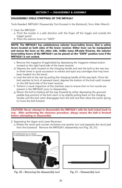
2. Separating the Upper and Lower Receivers:<br />
a. Rotate the recoil pad counter clockwise one quarter turn and separate the recoil pad<br />
from the buttstock. Remove the <strong>MR762A1</strong> disassembly tool (Fig. 20, 21).<br />
Fig. 24A – Removing the upper receiver<br />
Fig. 24B – Removing Bolt & Charging Handle<br />
b. Insert the small tip of the disassembly tool into the right hand side of the firing pin<br />
retaining pin and drift the firing pin retaining pin from right to left until the firing pin<br />
retaining pin reaches its limit of lateral travel (Fig. 25).<br />
WARNING: The firing pin retaining pin is a captive pin and will therefore remain<br />
attached to the bolt carrier. Attempting to completely remove the firing pin retaining<br />
pin could lead to damage of the bolt assembly.<br />
Fig. 20 – Removing the disassembly tool<br />
Fig. 21 – Disassembly tool<br />
22 23