
You also want an ePaper? Increase the reach of your titles
YUMPU automatically turns print PDFs into web optimized ePapers that Google loves.
Proximity Sensors Selection Guide<br />
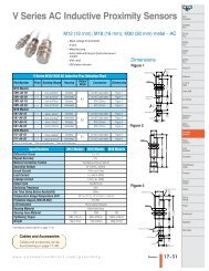
<strong>PROXIMITY</strong> <strong>SENSOR</strong> <strong>SELECTION</strong> <strong>GUIDE</strong><br />
Specifications PY Stainless Steel DC PD Stainless Steel DC AE Series DC AM Series DC<br />
Description<br />
Miniature inductive prox sensors,<br />
3mm and 4mm, DC, stainless steel<br />
Standard distance: 0.6mm<br />
Sensing Distances Extended distance: 1mm<br />
Miniature inductive proximity<br />
sensors, 5mm, DC, stainless steel<br />
Standard distance: 0.8mm<br />
Extended distance:1.5mm<br />
Inductive proximity sensors, 8mm, DC, metal,<br />
standard and short body lengths<br />
Standard distance: 0 to 1.5mm 0 to 2.5mm<br />
Extended distance: 0 to 2.0mm 0 to 4mm<br />
Triple distance: 0 to 3mm<br />
Output State N.0. N.0. N.0. N.0.<br />
Inductive proximity sensors, 12mm, DC,<br />
metal, standard and short body lengths<br />
Standard shielded: 0 to 2.0mm<br />
Standard unshielded: 0 to 4mm<br />
Extended shielded: 0 to 4mm<br />
Extended unshielded: 0 to 8mm<br />
Triple distance shielded: 6mm<br />
Logic Output NPN / PNP NPN / PNP NPN / PNP NPN / PNP / Sink / Source<br />
Connection Type Axial cable Axial cable / M8 connector Axial cable /M8 / M12 connector Axial cable / M12 connector<br />
Supply Voltage 10-30VDC 10-30VDC 10-30VDC 10-30VDC<br />
Switching<br />
Frequency<br />
Standard distance: 5kHz<br />
Extended distance: 3kHz<br />
Standard distance: 5kHz<br />
Extended distance: 3kHz<br />
Standard shielded: 3kHz<br />
Unshielded: 2.5kHz<br />
Extended shielded/unshielded: 3kHz<br />
Triple shielded: 1kHz<br />
Protection Degree IEC-IP67 IEC-IP67 IEC-IP67 IEC-IP67<br />
Prices start at <br />
Page<br />
17–16 17–17 17–18 17–21<br />
Standard distance shielded/unshielded:<br />
3 wire 2kHZ, 2 wire: 1.5kHz<br />
Extended distance shielded/unshielded: 1kHz<br />
Triple distance shielded: 800Hz<br />
Specifications AK Series DC AT Series DC PMW Stainless Steel DC PKW Stainless Steel DC<br />
Description<br />
Inductive proximity sensors, 18mm,<br />
DC, metal<br />
Inductive proximity sensors, 30mm,<br />
DC, metal<br />
Inductive proximity sensors, 12mm,<br />
stainless steel, DC<br />
Inductive proximity sensors, 18mm,<br />
stainless steel, DC<br />
Sensing<br />
Distances<br />
Standard distance: shielded 5mm,<br />
unshielded 8mm<br />
Extended distance: shielded, 8mm,<br />
unshielded 12mm<br />
Standard distance shielded: 10mm,<br />
Standard distance unshielded: 15mm<br />
Extended distance shielded: 15mm<br />
Extended distance unshielded: 20mm<br />
Standard distance: 2mm<br />
Extended distance: 4mm<br />
Triple distance: 6mm<br />
Standard distance: 5mm<br />
Extended distance: 8mm<br />
Triple distance: 10mm<br />
Output State N.0. N.0. N.0./ N.C. N.0. / N.C.<br />
Logic Output NPN / PNP / Sink / Source NPN / PNP / Sink / Source NPN / PNP NPN / PNP<br />
Connection Type Axial cable / M12 connector Axial cable / M12 connector Axial Cable / M12 connector Axial cable / M12 connector<br />
Supply Voltage 10-30VDC 10-30VDC 10-30VDC 10-30VDC<br />
Switching<br />
Frequency<br />
Protection Degree IEC-IP67<br />
Standard distance shielded: 600Hz<br />
Standard distance unshielded,<br />
Extended distance shielded,<br />
unshielded: 300Hz<br />
Standard distance shielded/unshielded:<br />
2 wire: 150Hz, 3 wire 200Hz<br />
Extended distance shielded/unshielded:<br />
2 wire and 3 wire: 150Hz<br />
IEC-IP67<br />
Standard distance/extended distance: 2kHz<br />
Triple distance: 400Hz<br />
Standard/extended distance:<br />
IEC-IP67/68<br />
Triple distance:<br />
IEC-IP67 connector / IP68 (Cable)<br />
Prices start at <br />
Page<br />
17–24 17–26 17–28 17–30<br />
Standard/extended distance: 1kHz<br />
Triple distance: 200Hz<br />
Standard/extended distance: IEC-IP67/68<br />
Triple distance: IEC-IP67 connector/IP68<br />
(Cable)<br />
17–10<br />
Sensors<br />
1-800-633-0405
Proximity Sensors Selection Guide<br />
<strong>PROXIMITY</strong> <strong>SENSOR</strong> <strong>SELECTION</strong> <strong>GUIDE</strong><br />
Proximity Sensor Selection Guide<br />
Specifications PTW Stainless Steel DC V Series AC CR5 Rectangular DC CR8 Rectangular DC<br />
Description<br />
Sensing Distances 20mm<br />
Inductive proximity sensors, 30mm,<br />
DC, stainless steel<br />
12mm/18mm/30mm inductive proximity<br />
sensor, AC, metal<br />
M12 models shielded: 2mm / Unshielded: 4mm<br />
M18 models shielded:5mm / Unshielded: 8mm<br />
M30 models shielded 10mm / Unshielded 15mm<br />
5 x 5 rectangular inductive proximity<br />
sensors, DC, metal<br />
Standard: 0.8mm<br />
Extended distance: 1.5mm<br />
Output State N.0. N.0. N.0. N.0.<br />
Logic Output NPN / PNP - NPN / PNP NPN / PNP<br />
8 x 8 rectangular inductive proximity<br />
sensors, DC, metal<br />
Standard distance shielded: 0 to 1.5mm<br />
Extended distance shielded: 0 to 2.0mm<br />
Triple distance shielded: 3mm<br />
Connection Type Axial Cable / M12 connector Axial cable / M12 connector Axial cable / M8 connector Axial cable / M8 connector<br />
Supply Voltage 10-30VDC 20-253VAC, 50/60Hz 10-30VDC 10-30VDC<br />
Switching<br />
Frequency<br />
100Hz<br />
25Hz<br />
Standard distance: 5kHz<br />
Extended distance: 3kHz<br />
Protection Degree IEC-IP67 (connector/ IP68 cable) IEC-IP67 IEC-IP67 IEC-IP67<br />
Prices start at <br />
Page<br />
17–32 17–33<br />
17–35 17–36<br />
1kHz<br />
Specifications DR10 Rectangular DC APS4 Rectangular DC CT Capacitive DC<br />
Description 10 x 16 rectangular inductive prox sensor, DC, plastic 12 x 27 compact rectangular inductive prox, DC, plastic 30mm capacitive proximity sensors, DC, metal<br />
Sensing Distances<br />
Shielded: 3mm<br />
Unshielded: 6mm<br />
Output State N.0. N.0. N.0.<br />
4.0mm<br />
Shielded: 2-15mm<br />
Unshielded: 2-20mm<br />
Logic Output NPN/ PNP NPN / PNP NPN/ PNP<br />
Connection Type Axial cable/M8 connector Axial cable Axial cable<br />
Supply Voltage 10-30VDC 10-30VDC 10-30VDC<br />
Switching Frequency 3kHz 200Hz 100Hz<br />
Protection Degree Rating IEC-IP67 IEC-IP67 IEC-IP65<br />
Prices start at <br />
Page<br />
17–38 17–39<br />
17–40<br />
<strong>SENSOR</strong>S<br />
Cables and Accessories<br />
Cables and accessories can be<br />
found starting on page 17–48.<br />
www.automationdirect.com/proximity Sensors 17–11
Proximity Sensors Selection Guide<br />
<strong>PROXIMITY</strong> <strong>SENSOR</strong> <strong>SELECTION</strong> <strong>GUIDE</strong><br />
Specifications AE Analog Prox AM Analog Prox AK Analog Prox AT Analog Prox<br />
Description<br />
Analog inductive proximity sensors,<br />
8mm, metal<br />
Analog inductive proximity sensors,<br />
12mm, metal<br />
Analog inductive proximity sensors,<br />
18mm, metal<br />
Sensing Distance 4mm 6mm 10mm 20mm<br />
Analog inductive proximity sensors,<br />
30mm, metal<br />
Output 0-10VDC 0-5VDC, 1-5mA / 0-10VDC, 4-20mA 0-5VDC, 1-5mA / 0-10VDC, 4-20mA 0-5VDC, 1-5mA / 0-10VDC, 4-20mA<br />
Supply Voltage 15-30VDC 10-30VDC / 15-30VDC 10-30VDC, 15-30VDC 10-30VDC / 15-30VDC<br />
Connection Type Axial cable / M8 connector Axial cable / M12 connector Axial cable / M12 connector Axial cable / M12 connector<br />
Protection Degree IEC-IP67 IEC-IP67 IEC-IP67 IEC-IP67<br />
Prices start at <br />
Page<br />
17–41 17–42 17–43 17–44<br />
Specifications SU Ultrasonic Sensor TU Ultrasonic Sensor<br />
Description<br />
Sensing Distances<br />
Output<br />
Supply Voltage<br />
Ultrasonic Sensor, 18mm, plastic,<br />
DC and analog output models<br />
100 to 600mm<br />
200 to 1500mm<br />
DC models: PNP N.O.<br />
Analog models: 0-10VDC<br />
DC models: 15-30VDC<br />
Analog models: 18-30VDC<br />
Ultrasonic Sensor, 30mm, plastic,<br />
DC and analog output models<br />
300 to 2500mm<br />
DC models: PNP N.O.<br />
Analog models: 0-10VDC<br />
19-30VDC<br />
Connection Type Axial cable/M12 connector M12 connector<br />
Protection Degree IEC-IP67 IEC-IP67<br />
Prices start at <br />
Page<br />
17–45 17–47<br />
17–12<br />
Sensors<br />
1-800-633-0405
Proximity Sensors Selection<br />
HOW DO I CHOOSE THE RIGHT <strong>SENSOR</strong>?<br />
All applications have certain specific<br />
needs, but, in general, the following steps<br />
will help you choose the correct sensor for<br />
your application:<br />
Step 1:<br />
What is the sensing distance required?<br />
The sensing distance is the distance<br />
between the tip of the sensor and the<br />
object to be sensed. The selection guide<br />
and the specifications table for each<br />
sensor family lists the sensing distances.<br />
Some things to keep in mind are:<br />
A. In many applications, it is beneficial to<br />
place the sensor as far as possible from the<br />
sensing object due to temperature<br />
concerns. If a sensor is placed too close to<br />
a hot temperature source, the sensor will<br />
fail quicker and require more<br />
maintenance.<br />
Greater distance may be achieved with<br />
extended and triple range sensors. In<br />
many applications, a sensor may not be<br />
mountable close to the sensed object. In<br />
this case, longer sensing distances are<br />
needed. The Centsable product line<br />
offers extended sensing distance sensors<br />
from 8mm to 30mm, and triple sensing<br />
distance sensors in 8mm and 12mm<br />
round formats.<br />
In many cases, using an extended distance<br />
sensor to get the sensor farther away from<br />
the detected object can be beneficial to<br />
the life of the sensor. For example,<br />
without an extended distance sensor you<br />
may not be able to place the sensor close<br />
enough to the detectable object, or you<br />
may need to buy more expensive high<br />
temperature sensors.<br />
Another example would be a mechanical<br />
overshoot situation, where mounting the<br />
sensor farther from the detection object<br />
may eliminate unneeded contact with the<br />
sensor, thereby extending the life of the<br />
sensor.<br />
These are just a few examples, but the<br />
benefits of using extended distance<br />
sensors are obvious in many applications.<br />
Think of how extended distance sensors<br />
could save you time and money in your<br />
application.<br />
B. The material being sensed (i.e. brass,<br />
copper, aluminum, steel, etc.) makes a<br />
difference in the type of sensor needed.<br />
Note: If you are sensing a non-metallic<br />
object, you must use a capacitive sensor.<br />
The sensing distances specified in this<br />
desk reference were calculated using<br />
FE360 material. Many materials are more<br />
difficult to sense and require a shorter<br />
distance from the sensor tip to the object<br />
sensed.<br />
If sensing a material that is difficult to<br />
sense, you may consider using our unique<br />
stainless steel sensing technology. This<br />
will measure virtually all materials at the<br />
specified sensing distances.<br />
Step 2:<br />
How much space is available for<br />
mounting the sensor?<br />
Have you ever tried using a round sensor<br />
or short body versions, and not been able<br />
to make it fit? Our rectangular sensors<br />
can meet your needs. The same technology<br />
used in a standard round proximity<br />
sensor is enclosed in a rectangular<br />
housing. This technology includes<br />
sensing distances, electrical protection<br />
and switching frequencies similar to<br />
round sensors.<br />
Round sensors<br />
Rectangular sensors<br />
Step 3:<br />
Is a shielded or unshielded sensor<br />
needed?<br />
Shielded and unshielded sensors are also<br />
referred to as embeddable and nonembeddable.<br />
Unshielded sensors allow<br />
longer sensing distances but shielded<br />
sensors allow flush mounting.<br />
Shielded sensor<br />
(embeddable)<br />
Unshielded sensor<br />
(non-embeddable)<br />
Step 4:<br />
Consider environmental placement<br />
concerns. Will the sensor be placed<br />
underwater, in a high-temperature environment,<br />
continually splashed with oil,<br />
etc.? This will determine the type of<br />
sensor you may use. In the selection table<br />
and in the specification tables for each<br />
sensor family, we list the environmental<br />
protection degree ratings. Most of our<br />
sensors are rated IEC-IP67 and others are<br />
rated IP65 or IP68.<br />
These ratings are defined as:<br />
IP65: Protection from live or moving<br />
parts, dust, and protection from water jets<br />
from any direction.<br />
IP67: Protection from live or moving<br />
parts, dust, and protection from immersion<br />
in water.<br />
IP68: Protection from live or moving<br />
parts, dust, and protection from submersion<br />
in water under pressure.<br />
<strong>SENSOR</strong>S<br />
www.automationdirect.com/proximity Sensors 17–13
Proximity Sensor Selection<br />
HOW DO I CHOOSE THE RIGHT <strong>SENSOR</strong>?<br />
Step 5:<br />
What is the sensor output connected to?<br />
Note: If using AC sensors, please skip this<br />
step.<br />
The type of output required must be<br />
determined (i.e., NPN, PNP or analog).<br />
Most PLC products will accept either<br />
output. If connecting to a solid state<br />
relay, a PNP output is needed.<br />
Step 6a:<br />
Do I need 2, 3, or 4-wire discrete<br />
outputs?<br />
This is somewhat determined by what the<br />
sensor will be connected to. Some simple<br />
guidelines to use are:<br />
2-wire<br />
3-wire<br />
4-wire<br />
Type<br />
Guidelines<br />
• Will work with sinking or sourcing . . .<br />
devices.<br />
• Only 2 wires to terminate.<br />
• Higher leakage current.<br />
• Most popular output. Familiar to most<br />
users. (Must select between NPN and<br />
PNP outputs.)<br />
• Allows configurability in one device. .<br />
May have both NPN/PNP selection or<br />
NO/NC selection. Allows user to stock<br />
one part for numerous applications.<br />
Step 6b:<br />
Do I need analog outputs?<br />
This is determined by the sensor application<br />
and what the sensor will be<br />
connected to. Devices with analog<br />
outputs produce an analog output signal<br />
approximately proportional to the target<br />
distance.<br />
Step 7:<br />
Determine output connection type.<br />
Do you want an axial cable factory<br />
attached to the sensor (pigtail) or a quickdisconnect<br />
cable?<br />
There are many advantages to using a<br />
quick-disconnect cable, such as easier<br />
maintenance and replacement. All proximity<br />
sensors will fail in time and using a<br />
Q/D (quick disconnect) cable allows for<br />
simple replacement.<br />
Factory attached axial cables come in a<br />
pre-determined 2m length. CD08/CD12<br />
Q/D cables come in 2m, 5m, and 7m<br />
lengths. Extension cables are available in<br />
1m and 3m lengths to extend the length<br />
of the standard Q/D cables.<br />
Q/D cables are offered in PVC and PUR<br />
jackets for meeting the requirements of<br />
all applications. Axial cables typically<br />
come with a PVC jacket. PVC is a general<br />
purpose insulation while PUR provides<br />
excellent oxidation, oil and ozone resistance.<br />
PUR is beneficial if the cable is<br />
exposed to oils or placed in direct<br />
sunlight.<br />
There are also advantages to a factory<br />
attached axial cable:<br />
Cost: The cable is integrated into the<br />
sensor and included in the price. Q/D<br />
cables must be purchased separately.<br />
Environmental impact: Since the cable is<br />
sealed into the sensor, there is less chance<br />
of oil, water or dust penetration into the<br />
sensor, which could cause failure.<br />
Type<br />
1-5mA<br />
4-20mA<br />
0-5VDC<br />
0-10VDC<br />
Guidelines<br />
available on AM9, AK9 and AT9 series<br />
analog inductive sensors<br />
available on AM9, AK9 and AT9 series<br />
analog inductive sensors<br />
available on AM9, AK9 and AT9 series<br />
analog inductive sensors<br />
available on AE9, AM9, AK9 and AT9<br />
series analog inductive sensors and<br />
SU and TU ultrasonic sensors<br />
17–14<br />
Sensors<br />
1-800-633-0405
Proximity Sensors Lifetime Warranty<br />
AUTOMATIONDIRECT LIFETIME WARRANTY<br />
Registration required<br />
For inductive proximity sensors sold to<br />
the Original User for the lifetime of the<br />
original application.<br />
The following terms apply to the LIFE-<br />
TIME WARRANTY in addition to the<br />
General Terms:<br />
1. This warranty is available only to<br />
AUTOMATIONDIRECT’s authorized Value Added<br />
Resellers and to the Original User. In the<br />
event the ownership of the product is transferred<br />
to a person, firm, or corporation<br />
other than the Original User, this WARRAN-<br />
TY shall terminate.<br />
2. This WARRANTY is applicable only to the<br />
original installation of the product. In the<br />
event the machinery, equipment, or production<br />
line to which the product is connected,<br />
or on which it is installed, is substituted,<br />
changed, moved or replaced, the WARRAN-<br />
TY shall terminate.<br />
3. This WARRANTY shall be valid only if the<br />
product was purchased by the Original User<br />
from AUTOMATIONDIRECT, or from an authorized<br />
AUTOMATIONDIRECT Value Added<br />
Reseller, or was an integral part of a piece of<br />
machinery and equipment obtained by the<br />
Original User from an original equipment<br />
manufacturer, where the part was purchased<br />
by the original equipment manufacturer<br />
directly from AUTOMATIONDIRECT or from<br />
an authorized AUTOMATIONDIRECT Value<br />
Added Reseller.<br />
Purchaser’s<br />
remedies<br />
This remedy shall apply<br />
to all WARRANTIES. If an<br />
AUTOMATIONDIRECT Value Added<br />
Reseller desires to make a WARRANTY<br />
claim, the Value Added Reseller shall, if<br />
requested by AUTOMATIONDIRECT, ship<br />
the product to AUTOMATIONDIRECT’s<br />
facility in Cumming, GA. postage or<br />
freight prepaid. If the Original User<br />
desires to make a WARRANTY Claim,<br />
they shall notify the authorized Value<br />
Added Reseller from whom it was<br />
purchased or, if purchased directly from<br />
AUTOMATIONDIRECT, shall notify<br />
AUTOMATIONDIRECT and, if requested by<br />
AUTOMATIONDIRECT, ship the Product to<br />
AUTOMATIONDIRECT’s facility in<br />
Cumming, GA. postage or freight<br />
prepaid. AUTOMATIONDIRECT shall, at its<br />
option, take any of the following two<br />
courses of action for any products which<br />
AUTOMATIONDIRECT determines are<br />
defective in materials or workmanship.<br />
1. Repair or replace the product and ship<br />
the product to the Original User or to the<br />
authorized AUTOMATIONDIRECT Value Added<br />
Reseller, postage or freight prepaid; or<br />
2.-Repay to the Original User that price paid<br />
by the Original User; provided that if the<br />
claim is made under the lifetime warranty,<br />
and such product is not then being supplied<br />
by AUTOMATIONDIRECT, then the amount to be<br />
repaid by AUTOMATIONDIRECT to the Original<br />
User shall be reduced according to the following<br />
schedule:<br />
REMEDIES OF PURCHASER’S AND VALUE ADDED RESELLERS SHALL BE<br />
LIMITED EXCLUSIVELY TO THE RIGHT OF REPLACEMENT, REPAIR OR<br />
REPAYMENT AS PROVIDED ABOVE AND DOES NOT INCLUDE ANY LABOR<br />
COST OR REPLACEMENT AT ORIGINAL USER’S SITE. AUTOMATIONDI-<br />
RECT.COM SHALL NOT BE LIABLE FOR ANY CONSEQUENTIAL DAMAGES<br />
RESULTING FROM ANY BREACH OF ANY WARRANTY, EXPRESSED OR<br />
IMPLIED, APPLICABLE TO THE PRODUCT, INCLUDING WITHOUT LIMITA-<br />
TION, ANY DAMAGES RESULTING FROM PROPERTY DAMAGE, PERSONAL<br />
INJURY OR BUSINESS INTERRUPTION, EVEN IF NOTIFIED OF THE POSSI-<br />
BILITY OF SUCH DAMAGES.<br />
Number of<br />
Years Since<br />
Date of<br />
Purchase by<br />
Original User<br />
10 50 percent<br />
15 25 percent<br />
20 10 percent<br />
More than 20<br />
Percent of Original<br />
Purchase Price To Be<br />
Paid by<br />
AutomationDirect<br />
5 percent<br />
<strong>SENSOR</strong>S<br />
www.automationdirect.com/proximity Sensors 17–15
Proximity Sensors Specifications<br />
PY SERIES INDUCTIVE <strong>PROXIMITY</strong> <strong>SENSOR</strong>S<br />
Miniature Ø3 (3mm) and M4 (4mm)<br />
stainless steel – DC<br />
• Smallest self-contained inductive proximity sensor<br />
available on the U.S. market<br />
• Eight models available<br />
• Complete overload protection<br />
• IP67 rated<br />
• Stainless steel construction<br />
• LED status indicator<br />
Dimensions<br />
PY Series Ø3 and M4 DC Inductive Prox Selection Chart<br />
Part Number Price Size Sensing<br />
Range<br />
Housing<br />
Output<br />
State<br />
Logic Connection Dimensions<br />
Standard Distance<br />
PY3-AN-1A Ø3*<br />
NPN 2m (6.5’) axial cable Figure 1<br />
PY3-AP-1A Ø3* 0.6mm<br />
PNP 2m (6.5’) axial cable Figure 1<br />
(0.024in)<br />
Shielded N.O.<br />
PY4-AN-1A 4mm NPN 2m (6.5’) axial cable Figure 2<br />
PY4-AP-1A 4mm PNP 2m (6.5’) axial cable Figure 2<br />
Extended Distance<br />
PY3-AN-3A Ø3*<br />
NPN 2m (6.5’) axial cable Figure 1<br />
PY3-AP-3A Ø3* 1mm<br />
PNP 2m (6.5’) axial cable Figure 1<br />
(0.039in)<br />
Shielded N.O<br />
PY4-AN-3A 4mm NPN 2m (6.5’) axial cable Figure 2<br />
PY4-AP-3A 4mm PNP 2m (6.5’) axial cable Figure 2<br />
*Smooth barrel, no threads<br />
Ø3 M4 Ø3 M4<br />
Specifications Standard Distance Extended Distance<br />
Type<br />
Shielded<br />
Operating Distance 0.6mm (0.024in) 1mm (0.039in)<br />
Material Correction Factors **See Material Influence table #1<br />
Differential Travel 10%<br />
Repeat Accuracy 5%<br />
Operating Voltage<br />
10-30VDC<br />
Ripple 20%<br />
No-load Supply Current<br />
10mA<br />
Load Current<br />
100mA<br />
Leakage Current 10µA 0.1mA<br />
Voltage Drop<br />
2.0 V<br />
Output Type<br />
NPN or PNP/N.O. only/three wire<br />
Switching Frequency 5KHz 3KHz<br />
(tv) Time Delay Before Availability<br />
10ms<br />
Input Voltage Transient Protection<br />
Up to 30VDC<br />
Input Power Polarity Reversal Protection<br />
Yes<br />
Output Power Short-Circuit Protection<br />
Yes (switch autoresets after overload is removed)<br />
Temperature Range -25° to +70° C (-13° to 158° F)<br />
Temperature Drift<br />
10% Sr<br />
Protection Degree (DIN 40050)<br />
IEC IP67<br />
LED Indicators<br />
Yellow (output energized)<br />
Housing Material<br />
Stainless steel<br />
Sensing Face Material<br />
Polyester<br />
Tightening Torque<br />
0.8Nm (7.08-in./lbs.)<br />
Weight 23g (0.81 oz) 22g (0.78 oz) 26g (0.92oz)<br />
**See Material Influence table #1 on page 17–53<br />
Figure 1 Figure 2<br />
LED<br />
Wiring diagrams<br />
PNP Output<br />
NPN Output<br />
Brown (1)<br />
+<br />
Black (4)<br />
Blue (3)<br />
Brown (1)<br />
+<br />
Black (4)<br />
Blue (3)<br />
–<br />
–<br />
LED<br />
Cables and<br />
Accessories<br />
Cables and accessories can be<br />
found starting on page 17–48.<br />
R L<br />
R L<br />
17–16<br />
Sensors<br />
1-800-633-0405
Proximity Sensors Specifications<br />
PD SERIES INDUCTIVE <strong>PROXIMITY</strong> <strong>SENSOR</strong>S<br />
Miniature M5 (5mm) stainless steel – DC<br />
• Eight models available<br />
• Stainless steel construction<br />
• Axial cable or M8 quick-disconnect<br />
models<br />
• Complete overload protection<br />
• IP67 rated<br />
• Smallest self-contained inductive proximity<br />
sensor available on the U.S. market<br />
• LED status indicator<br />
Part Number<br />
Price<br />
PD Series M5 DC Inductive Prox Selection Chart<br />
Sensing<br />
Range<br />
Housing<br />
Output<br />
State<br />
Logic Connection Dimensions<br />
Standard Distance<br />
PD1-AN-1A <br />
NPN 2m (6.5’) axial cable Figure 1<br />
PD1-AP-1A 0.8mm<br />
PNP 2m (6.5’) axial cable Figure 1<br />
(0.03in)<br />
Shielded N.O.<br />
PD1-AN-1F NPN M8 (8mm) connector Figure 2<br />
PD1-AP-1F PNP M8 (8mm) connector Figure 2<br />
Extended Distance<br />
PD1-AN-3A <br />
NPN 2m (6.5’) axial cable Figure 1<br />
PD1-AP-3A 1.5mm<br />
PNP 2m (6.5’) axial cable Figure 1<br />
(0.059in)<br />
Shielded N.O<br />
PD1-AN-3F NPN M8 (8mm) connector Figure 2<br />
PD1-AP-3F PNP M8 (8mm) connector Figure 2<br />
Dimensions<br />
M5x0.5<br />
.98”/<br />
25 mm<br />
.79”/<br />
20 mm<br />
Figure 1 Figure 2<br />
SW7<br />
.10”/<br />
2.5 mm<br />
.71”/<br />
18 mm<br />
LED<br />
03.5 mm<br />
1.50”/<br />
38 mm<br />
.91”/<br />
23 mm<br />
M5x0.5<br />
SW7<br />
.10”/<br />
2.5 mm<br />
.71”/<br />
18 mm<br />
.26”/<br />
06.5 mm<br />
M8x1<br />
Specifications<br />
Specifications<br />
Standard Distance Models Extended DistanceModels<br />
Type<br />
Shielded<br />
Operating Distance 0.8mm (0.03in) 1.5mm (0.059in)<br />
Material Correction Factors *See Material Influence table #1<br />
Differential Travel 10%<br />
Repeat Accuracy<br />
1.5%<br />
Operating Voltage<br />
10-30VDC<br />
Ripple 20%<br />
No-load Supply Current<br />
10mA<br />
Load Current<br />
200mA<br />
Leakage Current 10µA 0.1mA<br />
Voltage Drop<br />
2.0 V<br />
Output Type<br />
NPN or PNP/N.O. only/three wire<br />
Switching Frequency 5KHz 3KHz<br />
(tv) Time Delay Before Availability<br />
10ms<br />
Input Voltage Transient Protection<br />
Up to 30VDC<br />
Input Power Polarity Reversal Protection<br />
Yes<br />
Output Power Short-Circuit Protection<br />
Yes (switch autoresets after overload is removed)<br />
Temperature Range -25° to +70° C (-13° to 158° F)<br />
Temperature Drift<br />
10% Sr<br />
Protection Degree (DIN 40050)<br />
IEC IP67<br />
LED Indicators<br />
Yellow (output energized)<br />
Housing Material<br />
Stainless steel<br />
Sensing Face Material PBT Polyester<br />
Tightening Torque<br />
1.5Nm (13.3lb./in.)<br />
Weight (cable/M8 connector) 43g (1.52oz)/10g (0.36oz) 34g (1.20)/4g (0.14oz)<br />
*See Material Influence table #1 on page 17–53<br />
Wiring diagrams<br />
(OUT NO)<br />
S upply (+)<br />
NPN Output<br />
PNP Output<br />
M8 Connector<br />
1<br />
4<br />
Brown (1)<br />
+<br />
Black (4)<br />
Blue (3)<br />
3<br />
Connector on sensor<br />
–<br />
Brown (1)<br />
+<br />
Black (4)<br />
Blue (3)<br />
–<br />
R L<br />
R L<br />
S upply (--)<br />
Cables and<br />
Accessories<br />
Cables and accessories can be<br />
found starting on page 17–48.<br />
<strong>SENSOR</strong>S<br />
www.automationdirect.com/proximity Sensors 17–17
17–18<br />
Sensors<br />
Proximity Sensors Specifications<br />
AE SERIES INDUCTIVE <strong>PROXIMITY</strong> <strong>SENSOR</strong>S<br />
M8 (8mm) metal – DC<br />
• 24 standard length models available<br />
• 8 short body length models available<br />
Cables and Accessories<br />
• Compact metal housing<br />
• Axial cable, M8 or M12 quick-disconnect models Cables and accessories can be<br />
• Complete overload protection<br />
found starting on page 17–48.<br />
• IP67 rated<br />
• LED status indicators are visible 360 degrees around the cylinder<br />
AE1 Series Standard Length M8 DC Inductive Prox Selection Chart<br />
Part Number Price Sensing Range Housing Output State Logic Connection Wiring Dimensions<br />
Standard Distance<br />
AE1-AN-1A <br />
NPN 2m (6.5’) axial cable Diagram 1 Figure 1<br />
AE1-AP-1A PNP 2m (6.5’) axial cable Diagram 1 Figure 1<br />
AE1-AN-1H 0 to 1.5mm<br />
NPN M12 (12mm) connector Diagram 1 Figure 2<br />
(0-0.059in)<br />
Shielded<br />
N.O.<br />
AE1-AP-1H PNP M12 (12mm) connector Diagram 1 Figure 2<br />
AE1-AN-1F NPN M8 (8mm) connector Diagram 1 Figure 3<br />
AE1-AP-1F PNP M8 (8mm) connector Diagram 1 Figure 3<br />
AE1-AN-2A <br />
NPN 2m (6.5’) axial cable Diagram 1 Figure 1<br />
AE1-AP-2A PNP 2m (6.5’) axial cable Diagram 1 Figure 1<br />
AE1-AN-2H 0 to 2.5mm<br />
NPN M12 (12mm) connector Diagram 1 Figure 2<br />
(0-0.098in)<br />
Unshielded<br />
N.O.<br />
AE1-AP-2H PNP M12 (12mm) connector Diagram 1 Figure 2<br />
AE1-AN-2F NPN M8 (8mm) connector Diagram 1 Figure 3<br />
AE1-AP-2F PNP M8 (8mm) connector Diagram 1 Figure 3<br />
Extended Distance<br />
AE1-AN-3A <br />
NPN 2m (6.5’) axial cable Diagram 1 Figure 1<br />
AE1-AN-3F 0 to 2.0mm<br />
NPN M8 (8mm) connector Diagram 1 Figure 3<br />
(0-0.079in)<br />
Shielded<br />
N.O.<br />
AE1-AP-3A PNP 2m (6.5’) axial cable Diagram 1 Figure 1<br />
AE1-AP-3F PNP M8 (8mm) connector Diagram 1 Figure 3<br />
AE1-AN-4A <br />
NPN 2m (6.5’) axial cable Diagram 1 Figure 1<br />
AE1-AN-4F 0 to 4mm<br />
NPN M8 (8mm) connector Diagram 1 Figure 3<br />
(0-0.157in)<br />
Unshielded<br />
N.O.<br />
AE1-AP-4A PNP 2m (6.5’) axial cable Diagram 1 Figure 1<br />
AE1-AP-4F PNP M8 (8mm) connector Diagram 1 Figure 3<br />
Triple Distance<br />
AE1-AN-5A <br />
NPN 2m (6.5’) axial cable Diagram 2 Figure 4<br />
AE1-AP-5A 0 to 3mm<br />
PNP 2m (6.5’) axial cable Diagram 2 Figure 4<br />
(0-0.118in)<br />
Shielded<br />
N.O.<br />
AE1-AN-5F NPN M8 (8mm) connector Diagram 2 Figure 5<br />
AE1-AP-5F PNP M8 (8mm) connector Diagram 2 Figure 5<br />
AE6 Series Short Body M8 DC Inductive Prox Selection Chart<br />
Part Number Price Sensing Range Housing Output State Logic Connection Wiring Dimensions<br />
Extended Distance<br />
AE6-AN-3A <br />
NPN 2m (6.5’) axial cable Diagram 1 Figure 6<br />
AE6-AP-3A 0 to 2.0mm<br />
PNP 2m (6.5’) axial cable Diagram 1 Figure 6<br />
(0-0.079in)<br />
Shielded<br />
N.O.<br />
AE6-AN-3F NPN M8 (8mm) connector Diagram 1 Figure 7<br />
AE6-AP-3F PNP M8 (8mm) connector Diagram 1 Figure 7<br />
AE6-AN-4A <br />
NPN 2m (6.5’) axial cable Diagram 1 Figure 6<br />
AE6-AP-4A 0 to 4mm<br />
PNP 2m (6.5’) axial cable Diagram 1 Figure 6<br />
(0-0.157in)<br />
Unshielded<br />
N.O.<br />
AE6-AN-4F NPN M8 (8mm) connector Diagram 1 Figure 7<br />
AE6-AP-4F PNP M8 (8mm) connector Diagram 1 Figure 7<br />
1-800-633-0405
AE SERIES INDUCTIVE <strong>PROXIMITY</strong> <strong>SENSOR</strong>S<br />
Proximity Sensors Specifications<br />
Specifications Standard Distance Models Extended Distance Models Triple Distance Models<br />
Type Shielded Unshielded Shielded Unshielded Shielded<br />
Operating Distance 1.5mm (0.059in) 2.5mm (0.098in) 2mm (0.079in) 4mm (0.157in) 3mm (0.118in)<br />
Material Correction Factors *See Material Influence table #1 *See Material Influence table #2<br />
Differential Travel 2 to 10% 1 to 20% 10%<br />
Repeat Accuracy 2% 5%<br />
Operating Voltage<br />
10-30VDC<br />
Ripple 10% 20%<br />
No-load Supply Current 20mA 10mA<br />
Load Current<br />
200mA<br />
Leakage Current 10µA 120µA<br />
Voltage Drop 1.2 V 2.0 V<br />
Output Type<br />
NPN or PNP/N.O. only/3 wire<br />
Switching Frequency 3KHz 2.5KHz 3KHz 1KHz<br />
(tv) Time Delay Before Availability 100ms (5ms for AE6 short body models) 50ms<br />
Input Voltage Transient Protection<br />
Up to 30VDC<br />
Input Power Polarity Reversal Protection<br />
Yes<br />
Output Power Short-Circuit Protection<br />
Yes (switch autoresets after overload is removed)<br />
Temperature Range -25° to +70° C (-13° to 158° F)<br />
Temperature Drift<br />
10% Sr<br />
Protection Degree (DIN 40050)<br />
IEC IP67<br />
LED Indicators<br />
Yellow (output energized)<br />
Housing Material Nickel-plated brass Chrome-plated brass<br />
Sensing Face Material<br />
PBT<br />
Tightening Torque<br />
4Nm (35lb-in)<br />
Weight (cable/M8 connector/M12 connector) 43g (1.52oz)/16g (0.56oz)/20g (0.71oz) 54g (1.90oz)/26g (0.92oz)/(N/A)<br />
*See Material Influence tables #1 and #2 on page 17–53<br />
Wiring diagrams<br />
Diagram 1 Diagram 2 Connectors<br />
NPN output<br />
NPN output<br />
M8 connector<br />
LED<br />
T<br />
R<br />
D<br />
Brown (1)<br />
+<br />
Black (4)<br />
Brown (1)<br />
+<br />
R L<br />
Black (4)<br />
NP N out<br />
R L<br />
M8 Connector<br />
(OUT NO)<br />
4<br />
1 3<br />
S upply (+)<br />
S upply (--)<br />
Connector on sensor<br />
Z<br />
Blue (3)<br />
–<br />
Blue (3)<br />
–<br />
<strong>SENSOR</strong>S<br />
PNP output<br />
Brown (1)<br />
+<br />
PNP output<br />
Brown (1)<br />
+<br />
M12 connector<br />
M12 Connector<br />
(OUT NO) S upply (--)<br />
4 3<br />
1 2<br />
T<br />
Z<br />
Black (4)<br />
PNP out<br />
Black (4)<br />
S upply (+)<br />
Blue<br />
(OUT NC)<br />
Connector on sensor<br />
Black<br />
LED<br />
R L<br />
3<br />
4<br />
R<br />
D<br />
Blue (3)<br />
--<br />
R L<br />
Blue (3)<br />
–<br />
White<br />
2 1<br />
Connector on cable<br />
Brown<br />
www.automationdirect.com/proximity Sensors 17–19
Proximity Sensors Specifications<br />
AE SERIES INDUCTIVE <strong>PROXIMITY</strong> <strong>SENSOR</strong>S<br />
Dimensions<br />
Figure 1 Figure 2 Figure 3<br />
M8x1<br />
.37”/<br />
9.5 mm<br />
.24”/<br />
6mm<br />
1.97”/<br />
50 mm<br />
1.39”/<br />
35.3 mm<br />
.06”/<br />
01.5 mm .16”/<br />
4mm<br />
M8x1<br />
Figure 4<br />
Figure 5<br />
Figure 6<br />
Figure 7<br />
M8x1<br />
M8x1<br />
5.3<br />
LED<br />
9.5<br />
6<br />
35.5<br />
26.5<br />
40<br />
21.3<br />
4<br />
LED-o2x4<br />
4<br />
4<br />
SW 13<br />
o3.1<br />
M8x1<br />
17–20<br />
Sensors<br />
1-800-633-0405
Proximity Sensors Specifications<br />
AM SERIES INDUCTIVE PROXIMTY <strong>SENSOR</strong>S<br />
M12 (12mm) metal – DC<br />
• 26 standard length models available<br />
• 8 short body length models available<br />
• 2-wire and 3-wire models<br />
• Metal housing<br />
• Axial cable or M12 quick-disconnect models<br />
• Complete overload protection<br />
AM1 Series Standard Length M12 DC Inductive Prox Selection Chart<br />
• IP67 rated<br />
• LED status indicator<br />
• DC powered<br />
• Several sensing distances available<br />
Part Number Price Sensing Range Housing Output State Logic Connection Wiring Dimensions<br />
Standard Distance<br />
AM1-AN-1A <br />
NPN 2m (6.5’) axial cable Diagram 1 Figure 1<br />
AM1-AP-1A PNP 2m (6.5’) axial cable Diagram 1 Figure 1<br />
AM1-A0-1A 0 to 2.0mm<br />
Sink/source 2m (6.5’) axial cable Diagram 2 Figure 1<br />
(0-0.079in)<br />
Shielded<br />
N.O.<br />
AM1-AN-1H NPN M12 (12mm) connector Diagram 1 Figure 2<br />
AM1-AP-1H PNP M12 (12mm) connector Diagram 1 Figure 2<br />
AM1-A0-1H Sink/source M12 (12mm) connector Diagram 2 Figure 2<br />
AM1-AN-2A <br />
NPN 2m (6.5’) axial cable Diagram 1 Figure 1<br />
AM1-AP-2A PNP 2m (6.5’) axial cable Diagram 1 Figure 1<br />
AM1-A0-2A 0 to 4mm<br />
Sink/source 2m (6.5’) axial cable Diagram 2 Figure 1<br />
(0-0.157in)<br />
Unshielded<br />
N.O.<br />
AM1-AN-2H NPN M12 (12mm) connector Diagram 1 Figure 2<br />
AM1-AP-2H PNP M12 (12mm) connector Diagram 1 Figure 2<br />
AM1-A0-2H Sink/source M12 (12mm) connector Diagram 2 Figure 2<br />
Extended Distance<br />
AM1-AN-3A <br />
NPN 2m (6.5’) axial cable Diagram 1 Figure 1<br />
AM1-AP-3A PNP 2m (6.5’) axial cable Diagram 1 Figure 1<br />
AM1-A0-3A 0 to 4mm<br />
Sink/source 2m (6.5’) axial cable Diagram 2 Figure 1<br />
(0-0.157in)<br />
Shielded<br />
N.O.<br />
AM1-AN-3H NPN M12 (12mm) connector Diagram 1 Figure 2<br />
AM1-AP-3H PNP M12 (12mm) connector Diagram 1 Figure 2<br />
AM1-A0-3H Sink/source M12 (12mm) connector Diagram 2 Figure 2<br />
AM1-AN-4A <br />
NPN 2m (6.5’) axial cable Diagram 1 Figure 1<br />
AM1-AP-4A PNP 2m (6.5’) axial cable Diagram 1 Figure 1<br />
AM1-A0-4A 0 to 8mm<br />
Sink/source 2m (6.5’) axial cable Diagram 2 Figure 1<br />
(0-0.314in) Unshielded N.O.<br />
AM1-AN-4H NPN M12 (12mm) connector Diagram 1 Figure 2<br />
AM1-AP-4H PNP M12 (12mm) connector Diagram 1 Figure 2<br />
AM1-A0-4H Sink/source M12 (12mm) connector Diagram 2 Figure 2<br />
Triple Distance<br />
AM1-AN-5H 6mm<br />
NPN M12 (12mm) connector Diagram 3 Figure 3<br />
(0.236in)<br />
Shielded<br />
N.O.<br />
AM1-AP-5H PNP M12 (12mm) connector Diagram 3 Figure 3<br />
AM6 Series Short Body M12 DC Inductive Prox Selection Chart<br />
<strong>SENSOR</strong>S<br />
Part Number Price Sensing Range Housing Output State Logic Connection Wiring Dimensions<br />
Extended Distance<br />
AM6-AN-3A <br />
NPN 2m (6.5’) axial cable Diagram 1 Figure 4<br />
AM6-AP-3A
Proximity Sensors Specifications<br />
AM SERIES INDUCTIVE <strong>PROXIMITY</strong> <strong>SENSOR</strong>S<br />
Specifications Standard Distance Models Extended Distance Models Triple Distance Models<br />
Type Shielded Unshielded Shielded Unshielded Shielded<br />
Operating Distance 2mm (0.079in) 4mm (0.157in) 4mm (0.157in) 8mm (0.315in) 6mm (0.236in)<br />
Material Correction Factors *See Material Influence table #1 *See Material Influence table #2<br />
Differential Travel 2 to 10% 1 to 20%<br />
Repeat Accuracy 2% 5%<br />
Operating Voltage<br />
10-30VDC<br />
Ripple 10% 20%<br />
No Load Supply Current 20mA 10mA<br />
Load Current 3 wire: 200mA / 2 wire: 3-100mA 3 wire: 300mA / 2 wire: 3-100mA 200mA<br />
Leakage Current 3 wire: 10µA / 2 wire: 0.8mA 3 wire: 120µA / 2 wire: 0.8mA 100µA<br />
Voltage Drop 3 wire:1.2 volts max. / 2 wire: 2.8 volts max. 2.0V<br />
Output Type 3 wire: NPN or PNP, N.O. only/ 2 wire: sink/source, N.O. only NPN or PNP, N.O. only<br />
Switching Frequency 3 wire: 2KHz / 2 wire: 1.5KHz 3 wire: 1KHz / 2 wire: 1.5KHz 800Hz<br />
(tv) Time Delay Before Availability 3 wire: 100ms / 2 wire: 50ms 100ms<br />
Input Voltage Transient Protection<br />
Up to 30 VDC<br />
Input Power Polarity Reversal Protection<br />
Yes<br />
Output Power Short-Circuit Protection<br />
Yes (switch autoresets after overload is removed)<br />
Temperature Range -25° to + 70° C (-13° to 158° F)<br />
Temperature Drift<br />
10% Sr<br />
Protection Degree (DIN 40050)<br />
IEC IP67<br />
LED Indicators<br />
Yellow (N.O. output energized)<br />
Housing Material Nickel-plated brass Chrome-plated brass<br />
Sensing Face Material<br />
PBT<br />
Tightening Torque<br />
10Nm (88lb-in)<br />
Weight (cable/M12 connector) 70g (2.47oz)/30g (1.06oz) 96g (oz)/34g (oz)<br />
*See Material Influence tables #1 and #2 on page 17–53<br />
Wiring diagrams<br />
LED<br />
T<br />
Diagram 1 Diagram 2 Diagram 3 Connectors<br />
R<br />
Z<br />
D<br />
NPN Output<br />
BN/1<br />
BK/4=NO<br />
BK/2 NP N out<br />
BU/3<br />
+<br />
--<br />
L<br />
Z<br />
Sink/Source Output<br />
POS<br />
Brown<br />
NE G<br />
Black or Blue*<br />
Wiring diagram when sensor is wired in sinking<br />
mode used with a sourcing module.<br />
L<br />
+<br />
-<br />
NPN Output<br />
Brown (1)<br />
+<br />
Black (4)<br />
Blue (3)<br />
–<br />
R L<br />
M12 Connector<br />
(OUT NO) S upply (--)<br />
S upply (+)<br />
Blue<br />
White<br />
3-wire models<br />
4<br />
3<br />
1 2<br />
(OUT NC)<br />
Connector on sensor<br />
3<br />
4<br />
2 1<br />
Connector on cable<br />
Black<br />
Brown<br />
LED<br />
R<br />
T<br />
PNP Output<br />
BN/1<br />
+<br />
Z<br />
BK/4=NO<br />
BK/2<br />
D BU/3<br />
--<br />
PNP out<br />
L<br />
T<br />
Z<br />
Sink/Source Output<br />
POS<br />
Brown<br />
NE G<br />
Black<br />
or Blue*<br />
L<br />
+<br />
-<br />
PNP Output<br />
Brown (1)<br />
Black (4)<br />
Blue (3)<br />
+<br />
–<br />
R L<br />
NE G (--)<br />
Black<br />
POS (+)<br />
Brown<br />
Blue<br />
2-wire models<br />
M12 Connections<br />
Blue<br />
4 3<br />
1 2<br />
White<br />
Connector on sensor<br />
Black<br />
3 4<br />
2 1<br />
Wiring diagram when sensor is wired in sourcing<br />
mode used with a sinking module.<br />
* Note: Negative (-) lead is Black on M12 quickdisconnect<br />
cables and Blue on axial cables.<br />
White<br />
Brown<br />
Connector on cable<br />
17–22<br />
Sensors<br />
1-800-633-0405
Proximity Sensors Specifications<br />
AM SERIES INDUCTIVE <strong>PROXIMITY</strong> <strong>SENSOR</strong>S<br />
Dimensions<br />
Figure 1<br />
Figure 2<br />
Figure 3<br />
A<br />
B<br />
C<br />
D<br />
Dimensions<br />
Model A B C D<br />
3-wire (standard distance) 1.38in (35mm) 2.13in (54mm) 1.50in (38mm) 2.56in (65mm)<br />
3-wire (extended distance) 1.57in (40mm) 2.13in (54mm) 1.50in (38mm) 2.76in (70mm)<br />
2-wire (all) 1.77in (45mm) 2.36in (60mm) 1.89in (48mm) 2.95in (75mm)<br />
Cables and accessories<br />
Cables and accessories can be<br />
found starting on page 17–48.<br />
Figure 4<br />
M12x1<br />
Figure 5<br />
M12x1<br />
52.5<br />
15 30 5<br />
<strong>SENSOR</strong>S<br />
8<br />
40<br />
4 10 25 5<br />
LED<br />
4<br />
LED o2.5x4 SM 17<br />
o3.7<br />
M12x1<br />
www.automationdirect.com/proximity Sensors 17–23
Proximity Sensors Specifications<br />
AK SERIES INDUCTIVE <strong>PROXIMITY</strong> <strong>SENSOR</strong>S<br />
M18 (18mm) metal – DC<br />
• 24 models available<br />
• Standard and extended distance models available<br />
• 2-wire and 3-wire models<br />
• Axial cable or M12 quick-disconnect models available<br />
• Complete overload protection<br />
• IP67 rated<br />
• LED status indicators are visible 360° around the cylinder<br />
Dimensions<br />
AK Series M18 DC Inductive Prox Selection Chart<br />
Part Number Price Sensing Range Housing Output State Logic Connection Wiring Dimensions<br />
Standard Distance<br />
AK1-AN-1A <br />
NPN 2m (6.5’) axial cable Diagram 1 Figure 1<br />
AK1-AP-1A PNP 2m (6.5’) axial cable Diagram 1 Figure 1<br />
AK1-A0-1A Sink/source 2m (6.5’) axial cable Diagram 2 Figure 1<br />
5mm (0.197in) Shielded N.O.<br />
AK1-AN-1H NPN M12 (12mm) connector Diagram 1 Figure 2<br />
AK1-AP-1H PNP M12 (12mm) connector Diagram 1 Figure 2<br />
AK1-A0-1H Sink/source M12 (12mm) connector Diagram 2 Figure 2<br />
AK1-AN-2A <br />
NPN 2m (6.5’) axial cable Diagram 1 Figure 1<br />
AK1-AP-2A PNP 2m (6.5’) axial cable Diagram 1 Figure 1<br />
AK1-A0-2A Sink/source 2m (6.5’) axial cable Diagram 2 Figure 1<br />
8mm (0.315in) Unshielded N.O.<br />
AK1-AN-2H NPN M12 (12mm) connector Diagram 1 Figure 2<br />
AK1-AP-2H PNP M12 (12mm) connector Diagram 1 Figure 2<br />
AK1-A0-2H Sink/source M12 (12mm) connector Diagram 2 Figure 2<br />
Extended Distance<br />
AK1-AN-3A <br />
NPN 2m (6.5’) axial cable Diagram 1 Figure 1<br />
AK1-AP-3A PNP 2m (6.5’) axial cable Diagram 1 Figure 1<br />
AK1-A0-3A Sink/source 2m (6.5’) axial cable Diagram 2 Figure 1<br />
8mm (0.315in) Shielded N.O.<br />
AK1-AN-3H NPN M12 (12mm) connector Diagram 1 Figure 2<br />
AK1-AP-3H PNP M12 (12mm) connector Diagram 1 Figure 2<br />
AK1-A0-3H Sink/source M12 (12mm) connector Diagram 2 Figure 2<br />
AK1-AN-4A <br />
NPN 2m (6.5’) axial cable Diagram 1 Figure 1<br />
AK1-AP-4A PNP 2m (6.5’) axial cable Diagram 1 Figure 1<br />
AK1-A0-4A Sink/source 2m (6.5’) axial cable Diagram 2 Figure 1<br />
12mm (0.472in) Unshielded N.O.<br />
AK1-AN-4H NPN M12 (12mm) connector Diagram 1 Figure 2<br />
AK1-AP-4H PNP M12 (12mm) connector Diagram 1 Figure 2<br />
AK1-A0-4H Sink/source M12 (12mm) connector Diagram 2 Figure 2<br />
Figure 1 Figure 2<br />
Cables and accessories<br />
Cables and accessories can be<br />
found starting on page 17–48.<br />
17–24<br />
Sensors<br />
1-800-633-0405
AK SERIES INDUCTIVE <strong>PROXIMITY</strong> <strong>SENSOR</strong>S<br />
Wiring diagrams<br />
Proximity Sensors Specifications<br />
Specifications Standard Distance Models Extended Distance Models<br />
Type Shielded Unshielded Shielded Unshielded<br />
Material Correction Factors *See Material Influence table #1<br />
Differential Travel 2 to 10% 2 to 15%<br />
Repeat Accuracy 2% 5%<br />
Operating Voltage<br />
10-30VDC<br />
Ripple 10%<br />
Load Current<br />
3 wire: 400mA / 2 wire: 3-100mA<br />
Leakage Current<br />
3 wire: 10µA / 2 wire: 0.8mA max.<br />
Voltage Drop<br />
3 wire: 1 volt max. / 2 wire: 2.8V max.<br />
Output Type<br />
Three wire: NPN or PNP/N.O. (normally open) / Two wire: sink/source, N.O. only<br />
Switching Frequency 600Hz 300Hz<br />
(tv) Time Delay Before Availability<br />
3 wire: 100ms / 2 wire: 50ms<br />
Input Voltage Transients Protection<br />
Yes, as long as the transient peak does not exceed 30VDC<br />
Input Power Polarity Reversal Protection<br />
Yes<br />
Output Power Short-Circuit Protection<br />
Yes (switch autoresets after overload is removed)<br />
Temperature Range -25° to + 70° C (-13° to 158° F)<br />
Temperature Drift<br />
10% Sr<br />
Protection Degree (DIN 40050)<br />
IEC IP67<br />
LED Indicators<br />
Yellow (N.O. output energized)<br />
Housing Material<br />
Nickel-plated brass<br />
Sensing Face Material<br />
PBT<br />
Tightening Torque<br />
30Nm (22lbs/ft.)<br />
Weight<br />
A type (w/ cable): 130g (4.59oz) H type: 55g (1.94oz)<br />
*See Material Influence table #1 on page 17–53<br />
Diagram 1<br />
NPN Output<br />
PNP Output<br />
M12 Connector<br />
(OUT NO) S upply (--)<br />
LED<br />
T<br />
R<br />
Z<br />
D<br />
BN/1<br />
+<br />
BK/4=NO<br />
BK/2<br />
BU/3<br />
--<br />
L<br />
NPN out<br />
T<br />
LED<br />
R<br />
Z<br />
D<br />
BN/1<br />
+<br />
BK/4=NO<br />
BK/2<br />
BU/3<br />
--<br />
PNP out<br />
L<br />
S upply (+)<br />
Blue<br />
4 3<br />
1 2<br />
(OUT NC)<br />
Connector on sensor<br />
Black<br />
3 4<br />
2 1<br />
White<br />
Brown<br />
Diagram 2<br />
Connector on cable<br />
<strong>SENSOR</strong>S<br />
Z<br />
POS<br />
Brown<br />
NE G<br />
L<br />
Black or Blue*<br />
Wiring diagram when sensor is wired in sinking<br />
mode used with a sourcing module.<br />
+<br />
-<br />
T<br />
Z<br />
POS<br />
Brown<br />
NE G<br />
Black<br />
or Blue*<br />
Wiring diagram when sensor is wired in sourcing<br />
mode used with a sinking module.<br />
* Note: Negative (-) lead is Black on M12 quickdisconnect<br />
cables and Blue on axial cables.<br />
L<br />
+<br />
-<br />
NE G (--)<br />
Black<br />
POS (+)<br />
Brown<br />
Blue<br />
White<br />
M12 Connections<br />
Blue<br />
4 3<br />
1 2<br />
White<br />
Connector on sensor<br />
Black<br />
3 4<br />
2 1<br />
Brown<br />
Connector on cable<br />
www.automationdirect.com/proximity Sensors 17–25
Proximity Sensors Specifications<br />
AT SERIES INDUCTIVE <strong>PROXIMITY</strong> <strong>SENSOR</strong>S<br />
M30 (30mm) metal – DC<br />
• 24 models available<br />
• Standard and extended distance models available<br />
• 2-wire and 3-wire models<br />
• Axial cable or M12 quick-disconnect models<br />
• LED status indicators are visible 360° around the cylinder<br />
• Complete overload protection<br />
• IP67 rated<br />
Dimensions<br />
Figure 1<br />
AT Series M30 DC Inductive Prox Selection Chart<br />
Part Number Price Sensing Range Housing Output State Logic Connection Wiring Dimensions<br />
Standard Distance<br />
AT1-AN-1A <br />
NPN 2m (6.5’) axial cable Diagram 1 Figure 1<br />
AT1-AP-1A PNP 2m (6.5’) axial cable Diagram 1 Figure 1<br />
AT1-A0-1A Sink/source 2m (6.5’) axial cable Diagram 2 Figure 1<br />
10mm (0.394in) Shielded N.O.<br />
AT1-AN-1H NPN M12 (12mm) connector Diagram 1 Figure 2<br />
AT1-AP-1H PNP M12 (12mm) connector Diagram 1 Figure 2<br />
AT1-A0-1H Sink/source M12 (12mm) connector Diagram 2 Figure 2<br />
AT1-AN-2A <br />
NPN 2m (6.5’) axial cable Diagram 1 Figure 1<br />
AT1-AP-2A PNP 2m (6.5’) axial cable Diagram 1 Figure 1<br />
AT1-A0-2A Sink/source 2m (6.5’) axial cable Diagram 2 Figure 1<br />
15mm (0.591in) Unshielded N.O.<br />
AT1-AN-2H NPN M12 (12mm) connector Diagram 1 Figure 2<br />
AT1-AP-2H PNP M12 (12mm) connector Diagram 1 Figure 2<br />
AT1-A0-2H Sink/source M12 (12mm) connector Diagram 2 Figure 2<br />
Extended Distance<br />
AT1-AN-3A <br />
NPN 2m (6.5’) axial cable Diagram 1 Figure 1<br />
AT1-AP-3A PNP 2m (6.5’) axial cable Diagram 1 Figure 1<br />
AT1-A0-3A Sink/source 2m (6.5’) axial cable Diagram 2 Figure 1<br />
15mm (0.591in) Shielded N.O.<br />
AT1-AN-3H NPN M12 (12mm) connector Diagram 1 Figure 2<br />
AT1-AP-3H PNP M12 (12mm) connector Diagram 1 Figure 2<br />
AT1-A0-3H Sink/source M12 (12mm) connector Diagram 2 Figure 2<br />
AT1-AN-4A <br />
NPN 2m (6.5’) axial cable Diagram 1 Figure 1<br />
AT1-AP-4A PNP 2m (6.5’) axial cable Diagram 1 Figure 1<br />
AT1-A0-4A Sink/source 2m (6.5’) axial cable Diagram 2 Figure 1<br />
20mm (0.787in) Unshielded N.O.<br />
AT1-AN-4H NPN M12 (12mm) connector Diagram 1 Figure 2<br />
AT1-AP-4H PNP M12 (12mm) connector Diagram 1 Figure 2<br />
AT1-A0-4H Sink/source M12 (12mm) connector Diagram 2 Figure 2<br />
Figure 2<br />
Cables and accessories<br />
Cables and accessories can be<br />
found starting on page 17–48.<br />
17–26<br />
Sensors<br />
1-800-633-0405
AT SERIES INDUCTIVE <strong>PROXIMITY</strong> <strong>SENSOR</strong>S<br />
Wiring diagrams<br />
Diagram 1<br />
NPN Output<br />
LED<br />
T<br />
R<br />
Z<br />
D<br />
Diagram 2<br />
Z<br />
BN/1<br />
BK/4=NO<br />
BK/2<br />
BU/3<br />
POS<br />
Brown<br />
+<br />
--<br />
L<br />
NPN out<br />
L<br />
Black or Blue*<br />
PNP Output<br />
LED<br />
R<br />
T<br />
Z<br />
D<br />
BN/1<br />
BK/4=NO<br />
BK/2<br />
BU/3<br />
+<br />
--<br />
PNP out<br />
L<br />
M12 Connector<br />
(OUT NO) S upply (--)<br />
S upply (+)<br />
Blue<br />
White<br />
Proximity Sensors Specifications<br />
Specifications Standard Distance Models Extended Distance Models<br />
Type Shielded Unshielded Shielded Unshielded<br />
Material Correction Factors *See Material Influence table #1<br />
Differential Travel 2 to 10% 2 to 15%<br />
Repeat Accuracy 3 wire: 2% / 2 wire: 5% 2 and 3 wire: 5%<br />
Operating Voltage<br />
10-30VDC<br />
Ripple 10%<br />
Load Current 3 wire: 400mA / 2 wire: 3-100mA 2 and 3 wire:400mA<br />
Leakage Current 3 wire:10µA / 2 wire: 0.8mA max. 3 wire 8µA / 2 wire: 0.8mA max.<br />
Voltage Drop 3 wire: 1 volt max. / 2 wire: 2.8V 3 wire: 1 volt max. / 2 wire: 2.8V<br />
Output Type<br />
NE G<br />
Wiring diagram when sensor is wired in sinking<br />
mode used with a sourcing module.<br />
+<br />
-<br />
T<br />
Z<br />
POS<br />
Brown<br />
NE G<br />
Black<br />
or Blue*<br />
Wiring diagram when sensor is wired in sourcing<br />
mode used with a sinking module.<br />
* Note: Negative (-) lead is Black on M12 quickdisconnect<br />
cables and Blue on axial cables.<br />
L<br />
Three wire: NPN or PNP/N.O. (normally open) / Two wire: sink/source, N.O. only<br />
Switching Frequency 3 wire: 200Hz / 2 wire: 150Hz 2 and 3 wire:150Hz<br />
(tv) Time Delay Before Availability 3 wire: 100ms / 2 wire: 50ms 3 wire:100ms / 2 wire: 50ms<br />
Input Voltage Transients Protection<br />
Input Power Polarity Reversal Protection<br />
Output Power Short-Circuit Protection<br />
+<br />
-<br />
Yes, as long as the transient peak does not exceed 30VDC<br />
NE G (--)<br />
Black<br />
POS (+)<br />
Brown<br />
www.automationdirect.com/proximity Sensors 17–27<br />
Blue<br />
White<br />
4<br />
3<br />
1 2<br />
(OUT NC)<br />
Connector on sensor<br />
3<br />
4<br />
2 1<br />
Connector on cable<br />
M12 Connections<br />
4<br />
3<br />
1 2<br />
Black<br />
Brown<br />
Blue<br />
White<br />
Connector on sensor<br />
3<br />
4<br />
2 1<br />
Yes<br />
Yes (switch autoresets after overload is removed)<br />
Temperature Range -25° to + 70° C (-13° to 158° F)<br />
Temperature Drift<br />
Protection Degree (DIN 40050)<br />
LED Indicators<br />
Housing Material<br />
Sensing Face Material<br />
Tightening Torque<br />
Weight<br />
*See Material Influence table #1 on page 17–53<br />
10% Sr<br />
IEC IP67<br />
Yellow (N.O. output energized)<br />
Nickel-plated brass<br />
PBT<br />
60Nm (44lbs./ft.)<br />
A type (w/ cable): 180g (6.35oz) H type: 110g (3.88oz)<br />
Black<br />
Brown<br />
Connector on cable<br />
<strong>SENSOR</strong>S
Proximity Sensors Specifications<br />
PMW SERIES INDUCTIVE <strong>PROXIMITY</strong> <strong>SENSOR</strong>S<br />
M12 (12mm) stainless steel – DC<br />
• 8 models available<br />
• Low cost/high performance<br />
• IP67 rated<br />
• LED status indicators are visible at a wide angle<br />
• Triple distance models (shown) sense all metals at virtually the same distance, have one-piece<br />
stainless design, and are fully submersible up to 290 psi. Axial cable models have IP68 protection<br />
degree.<br />
PMW Series M12 DC Inductive Prox Selection Chart<br />
Part Number Price Sensing Range Housing Output State Logic Connection Wiring Dimensions<br />
Standard Distance<br />
PMW-0N-1H <br />
NPN M12 (12mm) connector Diagram 1 Figure 1<br />
2mm (0.079in) Shielded N.O./N.C<br />
PMW-0P-1H PNP M12 (12mm) connector Diagram 1 Figure 1<br />
Extended Distance<br />
PMW-0N-2H <br />
NPN M12 (12mm) connector Diagram 1 Figure 1<br />
4mm (0.157in) Unshielded N.O./N.C<br />
PMW-0P-2H PNP M12 (12mm) connector Diagram 1 Figure 1<br />
Triple Distance<br />
PMW-AN-5A <br />
NPN 2m (6.5’) axial cable Diagram 2 Figure 2<br />
PMW-AP-5A PNP 2m (6.5’) axial cable Diagram 2 Figure 2<br />
6mm (0.236in) Shielded N.O.<br />
PMW-AN-5H NPN M12 (12mm) connector Diagram 2 Figure 3<br />
PMW-AP-5H PNP M12 (12mm) connector Diagram 2 Figure 3<br />
Wiring diagrams<br />
Diagram 1<br />
Diagram 2<br />
Connectors<br />
NPN output<br />
BN/1<br />
+<br />
NPN output<br />
Brown (1)<br />
+<br />
R L<br />
M12 Connector<br />
(OUT NO) S upply (--)<br />
4 3<br />
1 2<br />
WH/2=NC<br />
L<br />
L<br />
Black (4)<br />
S upply (+)<br />
(OUT NC)<br />
Connector on sensor<br />
BK/4=NO<br />
BU/3<br />
-<br />
NPN out<br />
Blue (3)<br />
–<br />
Blue<br />
3 4<br />
2 1<br />
Black<br />
White<br />
Brown<br />
Connector on cable<br />
PNP output<br />
PNP output<br />
BN/1<br />
+<br />
Brown (1)<br />
+<br />
BK/U=NO<br />
WH/2=NC<br />
BU/3<br />
-<br />
L<br />
PNP out<br />
L<br />
Black (4)<br />
Blue (3)<br />
–<br />
R L<br />
Cables and Accessories<br />
Cables and accessories can be<br />
found starting on page 17–48.<br />
17–28<br />
Sensors<br />
1-800-633-0405
Proximity Sensors Specifications<br />
PMW SERIES INDUCTIVE <strong>PROXIMITY</strong> <strong>SENSOR</strong>S<br />
Dimensions<br />
Specifications Standard Distance Models Extended Distance Models Triple Distance Models<br />
Type Shielded Unshielded Shielded<br />
Operating Distance 2mm (0.079in) 1 4mm (0.157in) 1 6mm (0.236in)<br />
Material Correction Factors *See Material Influence table #1 *See Material Influence table #3<br />
Differential Travel 2 to 10% 15%<br />
Repeat Accuracy 5%<br />
Operating Voltage<br />
10-30VDC<br />
Ripple 10% 20%<br />
Load Current 100mA 200mA<br />
Voltage Drop 1.2V 2.0V<br />
Output Type NPN or PNP and N.O./N.C. complementary NPN or PNP, N.O. only<br />
Leakage Current 10µA 100µA<br />
Switching Frequency 2KHz 400Hz<br />
(tv) Time Delay Before Availability 100ms 10ms<br />
Temperature Range / Temperature Drift<br />
-25° to +70° C (-13° to 158° F) / 10%Sr<br />
Protection Degree (DIN 40050) IEC IP67/68 2 IEC IP67 3 (connector/IP68 3 (cable)<br />
LED Indicators<br />
Yellow (N.O. output energized)<br />
Housing Material Stainless steel Stainless steel<br />
Sensing Face Material PPS Stainless steel<br />
Tightening Torque<br />
10Nm (7.25-in/ lbs)<br />
Weight 35g (1.23oz) 89g (3.14oz)/24g (0.85oz)<br />
1<br />
With 12 x 12mm FE360 target 2 Only with M12 connector in fully-tightened position. While this sensor has good resistance to chemicals and oil, it should be tested before using in a harsh environment.<br />
3 Fully submersible to 290 psi.<br />
*See Material Influence tables #1 and #3 on page 17–53<br />
Figure 1 Figure 2 Figure 3<br />
M12x1<br />
SW17<br />
<strong>SENSOR</strong>S<br />
.41 /<br />
10.3 mm<br />
.24 /<br />
6.2 mm<br />
.38 /<br />
9.6 mm<br />
1.28 /<br />
32.5 mm<br />
.24 /<br />
6.2 mm<br />
2.55 /<br />
64.8 mm<br />
.50 /<br />
012.7 mm<br />
www.automationdirect.com/proximity Sensors 17–29
Proximity Sensors Specifications<br />
PKW SERIES INDUCTIVE <strong>PROXIMITY</strong> <strong>SENSOR</strong>S<br />
M18 (18mm) stainless steel - DC<br />
• Eight models available<br />
• Low cost/high performance<br />
• IP67 rated<br />
• LED status indicators are visible at a wide angle<br />
• Triple distance models (shown) sense all metals at virtually the same distance,<br />
have one-piece stainless design, and are fully submersible up to 290<br />
psi. Axial cable models have IP68 protection degree.<br />
PKW Series M18 DC Inductive Prox Selection Chart<br />
Part Number Price Sensing Range Housing Output State Logic Connection Wiring Dimensions<br />
Standard Distance<br />
PKW-0N-1H <br />
NPN M12 (12mm) connector Diagram 1 Figure 1<br />
5mm (0.197in) Shielded N.O./N.C<br />
PKW-0P-1H PNP M12 (12mm) connector Diagram 1 Figure 1<br />
Extended Distance<br />
PKW-0N-2H <br />
NPN M12 (12mm) connector Diagram 1 Figure 1<br />
8mm (0.315in) Unshielded N.O./N.C<br />
PKW-0P-2H PNP M12 (12mm) connector Diagram 1 Figure 1<br />
Triple Distance<br />
PKW-AN-5A <br />
NPN 2m (6.5’) axial cable Diagram 2 Figure 2<br />
PKW-AP-5A PNP 2m (6.5’) axial cable Diagram 2 Figure 2<br />
10mm (0.394in) Shielded N.O.<br />
PKW-AN-5H NPN M12 (12mm) connector Diagram 2 Figure 3<br />
PKW-AP-5H PNP M12 (12mm) connector Diagram 2 Figure 3<br />
Wiring diagrams<br />
Diagram 1<br />
Diagram 2<br />
Connectors<br />
NPN output<br />
BN/1<br />
+<br />
NPN output<br />
Brown (1)<br />
+<br />
R L<br />
M12 Connector<br />
(OUT NO) S upply (--)<br />
4 3<br />
1 2<br />
WH/2=NC<br />
L<br />
L<br />
Black (4)<br />
S upply (+)<br />
(OUT NC)<br />
Connector on sensor<br />
BK/4=NO<br />
BU/3<br />
-<br />
NPN out<br />
Blue (3)<br />
–<br />
Blue<br />
3 4<br />
2 1<br />
Black<br />
White<br />
Brown<br />
Connector on cable<br />
PNP output<br />
PNP output<br />
BN/1<br />
+<br />
Brown (1)<br />
+<br />
BK/U=NO<br />
WH/2=NC<br />
BU/3<br />
-<br />
L<br />
PNP out<br />
L<br />
Black (4)<br />
Blue (3)<br />
–<br />
R L<br />
Cables and Accessories<br />
Cables and accessories can be<br />
found starting on page 17–48.<br />
17–30<br />
Sensors<br />
1-800-633-0405
Dimensions<br />
Figure 1 Figure 2 Figure 3<br />
Proximity Sensors Specifications<br />
PKW SERIES INDUCTIVE <strong>PROXIMITY</strong> <strong>SENSOR</strong>S<br />
Specifications Standard Distance Models Extended Distance Models Triple Distance Models<br />
Type Shielded Unshielded Shielded<br />
Operating Distance 5mm (0.197in) 1 8mm (0.315in) 1 10mm (0.394in)<br />
Material Correction Factors *See Material Influence table #1 *See Material Influence table #3<br />
Differential Travel 2 to 10% 15%<br />
Repeat Accuracy 5%<br />
Operating Voltage<br />
10-30VDC<br />
Ripple 10% 20%<br />
Load Current 400mA 200mA<br />
Voltage Drop 0.8V 2.0V<br />
Output Type NPN or PNP and N.O./N.C. complementary NPN or PNP, N.O. only<br />
Leakage Current 10µA 100µA<br />
Switching Frequency 1KHz 200Hz<br />
(tv) Time Delay Before Availability 100ms 10ms<br />
Temperature Range / Temperature Drift<br />
-25° to +70° C (-13° to 158° F) / 10%Sr<br />
Protection Degree (DIN 40050) IEC IP67/68 2 IEC IP67 3 (connector) IP68 3 (cable)<br />
LED Indicators<br />
Yellow (N.O. output energized)<br />
Housing Material Stainless steel Stainless steel<br />
Sensing Face Material PSU Stainless steel<br />
Tightening Torque 40Nm (29lb./ft.) 50Nm (37lb./ft.)<br />
Weight 70g (2.47oz) 114g (4.02oz)/50g (1.76oz)<br />
1<br />
With 12 x 12mm FE360 target 2 Only with M12 connector in fully-tightened position. While this sensor has good resistance to chemicals and oil, it should be tested before using in a harsh environment.<br />
3 Fully submersible to 290 psi.<br />
*See Material Influence tables # 1 and #3 on page 17–53<br />
M18x1<br />
.31 /<br />
8mm<br />
SW24<br />
.59 /<br />
15 mm<br />
2.48 /<br />
63 mm<br />
1.06 /<br />
27 mm<br />
<strong>SENSOR</strong>S<br />
.51 /<br />
13 mm<br />
M12x1<br />
.41 /<br />
010.5 mm<br />
www.automationdirect.com/proximity Sensors 17–31
Proximity Sensors Specifications<br />
PTW SERIES INDUCTIVE <strong>PROXIMITY</strong> <strong>SENSOR</strong>S<br />
M30 (30mm) stainless steel - DC<br />
• 4 models available/Low cost/high performance<br />
• M12 quick-disconnect models rated IP67,<br />
axial cable models rated IP68<br />
• LED status indicators are visible at a wide angle<br />
• Sense all metals at the same distance<br />
• One-piece stainless design<br />
Part Number<br />
PTW Series M30 DC SS Inductive Prox Selection Chart<br />
Price<br />
Wiring diagrams<br />
NPN output<br />
Sensing<br />
Range<br />
Brown (1)<br />
+<br />
Black (4)<br />
Housing<br />
Output<br />
State<br />
R L<br />
Logic Connection Dimensions<br />
PTW-AN-5A <br />
NPN 2m (6.5’) axial cable Figure 1<br />
PTW-AP-5A 20mm<br />
PNP 2m (6.5’) axial cable Figure 1<br />
(0.787in)<br />
Shielded N.O<br />
PTW-AN-5H NPN M12 (12mm) connector Figure 2<br />
PTW-AP-5H PNP M12 (12mm) connector Figure 2<br />
Type<br />
Operating Distance<br />
Specifications<br />
Shielded<br />
20mm (0.787in)<br />
Material Correction Factors *See Material Influence table #3<br />
Differential Travel 15%<br />
Repeat Accuracy 5%<br />
Operating Voltage<br />
10-30VDC<br />
Ripple 20%<br />
Load Current<br />
Voltage Drop<br />
Output Type<br />
Leakage Current<br />
Switching Frequency<br />
(tv) Time Delay Before Availability<br />
Temperature Range / Temperature Drift<br />
Protection Degree (DIN 40050)<br />
LED Indicators<br />
Housing Material<br />
Sensing Face Material<br />
Tightening Torque<br />
Weight<br />
1<br />
Fully submersible to 290 psi (20 bar).<br />
*See Material Influence table #3 on page 17–53<br />
200mA<br />
2.0V<br />
NPN or PNP, N.O. only<br />
100µA<br />
100Hz<br />
10ms<br />
-25° to +70° C (-13° to 158° F) / 10%Sr<br />
IEC IP67 1 (connector) IP68 1 (cable)<br />
Yellow (N.O. output energized)7<br />
Stainless steel<br />
Stainless steel<br />
150Nm (111lb./in.)<br />
114g (4.02oz)/50g (1.76oz)<br />
PNP output<br />
Brown (1)<br />
+<br />
Black (4)<br />
Dimensions<br />
Figure 1<br />
Figure 2<br />
Cables and accessories<br />
Cables and accessories can be<br />
found starting on page 17–48.<br />
M12 Connector<br />
(OUT NO) S upply (--)<br />
S upply (+)<br />
Blue<br />
4<br />
3<br />
1 2<br />
(OUT NC)<br />
Connector on sensor<br />
Black<br />
R L<br />
3<br />
4<br />
Blue (3)<br />
–<br />
Blue (3)<br />
–<br />
White<br />
2 1<br />
Brown<br />
17–32<br />
Sensors<br />
Connector on cable<br />
1-800-633-0405
Proximity Sensors Specifications<br />
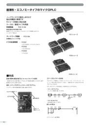
V SERIES AC INDUCTIVE <strong>PROXIMITY</strong> <strong>SENSOR</strong>S<br />
M12 (12mm), M18 (18mm), M30 (30mm)<br />
metal – AC<br />
• Multivoltage: 20 to 253VAC<br />
• 2-wire<br />
• Metal housing<br />
• Axial cable with tang or Quick-disconnect models<br />
• IP67 rated<br />
• LED status indicator<br />
Dimensions<br />
Figure 1<br />
V Series M12/18/30 AC Inductive Prox Selection Chart<br />
Part Number Price Sensing Range Housing<br />
Output<br />
State<br />
Connection Dimensions<br />
M12 Models<br />
VM1-A0-1B 2mm (0.079in) 1 Shielded<br />
2m (6.5’) axial cable Figure 1<br />
VM1-A0-2B 4mm (0.157in) 1 Unshielded 2m (6.5’) axial cable Figure 1<br />
N.O.<br />
VM1-A0-1H 2mm (0.079in)1 Shielded M12 (12mm) Figure 2<br />
VM1-A0-2H 4mm (0.157in)1 Unshielded M12 (12mm) Figure 2<br />
M18 Models<br />
VK1-A0-1B 5mm (.197in) 2 Shielded<br />
2m (6.5’) axial cable Figure 3<br />
VK1-A0-2B 8mm (0.315in) 2 Unshielded 2m (6.5’) axial cable Figure 3<br />
N.O.<br />
VK1-A0-1H 5mm (.197in)2 Shielded M12 (12mm) Figure 4<br />
VK1-A0-2H 8mm(0.315in)2 Unshielded M12 (12mm) Figure 4<br />
M30 Models<br />
VT1-A0-1B 10mm (.394in) 3 Shielded<br />
2m (6.5’) axial cable Figure 5<br />
N.O.<br />
VT1-A0-2B 15mm (0.591in) 3 Unshielded 2m (6.5’) axial cable Figure 5<br />
Figure 2<br />
SW17<br />
M12x1<br />
5<br />
1 With 12x12 Fe360 target 2 With 18x18 Fe360 target 3 With 30x30 Fe360 target<br />
40<br />
Specifications M12 Models M18 Models M30 Models<br />
65<br />
Differential Travel 2 to 10%<br />
Repeat Accuracy 5%<br />
Material Correction Factors *See Material Influence table #1<br />
Operating Voltage<br />
20–253VAC, 50/60Hz<br />
Inrush Current<br />
7A for up to 10ms<br />
Load Current<br />
5 to 300mA (RMS)<br />
Leakage Current<br />
1.0mA max. (RMS)<br />
Output Type<br />
Triac/NO/2 wire<br />
Switching Frequency<br />
25Hz<br />
(tv) Time Delay Before Availability<br />
200ms<br />
Temperature Range/Temperature Drift<br />
-25° to +70° C (-13° to 158° F) / 10% Sr<br />
Protection Degree (DIN 40 050)<br />
IEC IP67<br />
LED Indicators<br />
Yellow (output energized)<br />
Housing Material<br />
Nickel-plated brass<br />
Sensing Face Material PBT POM PBT<br />
Tightening Torque 15Nm (11lb./ft.) 40Nm (29lb./ft.) 100Nm (73lb./ft.)<br />
Weight 70g (2.47oz) 120g (4.23oz) 300g (10.6oz)<br />
Figure 3<br />
M12x1<br />
20<br />
<strong>SENSOR</strong>S<br />
*See Material Influence table #1 on page 17–53<br />
Cables and Accessories<br />
Cables and accessories can be<br />
found starting on page 17–48.<br />
www.automationdirect.com/proximity Sensors 17–33
Proximity Sensors Specifications<br />
V SERIES AC INDUCTIVE <strong>PROXIMITY</strong> <strong>SENSOR</strong>S<br />
Figure 4<br />
Figure 5<br />
M18x1<br />
M30x1.5<br />
.47 /<br />
12 mm<br />
SW36<br />
SW24<br />
15<br />
.83"/<br />
21mm<br />
3.84 /<br />
100 mm<br />
45<br />
73<br />
1.85 /<br />
47 mm<br />
8<br />
M12x1<br />
13<br />
.51 /<br />
013 mm<br />
.28 / .51 /<br />
7mm 13 mm<br />
Wiring diagram<br />
Connector Pinouts<br />
M12 Connector<br />
4<br />
3<br />
1 2<br />
Connector on sensor<br />
Blue<br />
Black<br />
White<br />
3 4<br />
2 1<br />
Connector on cable<br />
Brown<br />
17–34<br />
Sensors<br />
1-800-633-0405
Proximity Sensors Specifications<br />
CR5 SERIES INDUCTIVE <strong>PROXIMITY</strong> <strong>SENSOR</strong>S<br />
Part Number<br />
Cables and Accessories<br />
Cables and accessories can be<br />
found starting on page 17–48.<br />
5 x 5mm rectangular metal - DC<br />
• Eight models available<br />
• Compact 5 x 5 x 25mm metal housing<br />
• Axial cable or M8 quick-disconnect models<br />
• Complete overload protection<br />
• IP67 rated<br />
• Screws included<br />
CR5 Series 5x5 Rectangular DC Inductive Prox Selection Chart<br />
Price<br />
Sensing<br />
Range<br />
Specifications<br />
Standard Distance Models Extended Distance Models<br />
Type Shielded Shielded<br />
Operating Distance 0.8mm (0.03in) 1.5mm (0.059in)<br />
Material Correction Factors *See Material Influence table #1<br />
Differential Travel 10%<br />
Repeat Accuracy<br />
1.5%<br />
Operating Voltage<br />
10-30VDC<br />
Ripple 20%<br />
No-load Supply Current<br />
10mA<br />
Load Current<br />
200mA<br />
Leakage Current<br />
10µA<br />
Voltage Drop<br />
2.0 V<br />
Output Type<br />
NPN or PNP/N.O. only/three wire<br />
Switching Frequency 5KHz 3KHz<br />
(tv) Time Delay Before Availability<br />
10ms<br />
Input Voltage Transient Protection<br />
Up to 30VDC<br />
Input Power Polarity Reversal Protection<br />
Yes<br />
Output Power Short-Circuit Protection<br />
Yes (switch autoresets after overload is removed)<br />
Temperature Range -25° to +70° C (-13° to 158° F)<br />
Temperature Drift<br />
10% Sr<br />
Protection Degree (DIN 40050)<br />
IEC IP67<br />
LED Indicators<br />
Yellow (output energized)<br />
Housing Material<br />
Nickel-plated brass<br />
Sensing Face Material<br />
Polyester<br />
Tightening Torque<br />
1.5Nm (13.3lb./in)<br />
Weight 26g (0.92oz) 27g (0.95oz)<br />
*See Material Influence table #1 on page 17–53<br />
Housing<br />
Output<br />
State<br />
Logic Connection Dimensions<br />
Standard Distance<br />
CR5-AN-1A <br />
NPN 2m (6.5’) axial cable Figure 1<br />
CR5-AP-1A 0.8mm<br />
PNP 2m (6.5’) axial cable Figure 1<br />
(0.03in)<br />
Shielded N.O.<br />
CR5-AN-1F NPN M8 (8mm) connector Figure 2<br />
CR5-AP-1F PNP M8 (8mm) connector Figure 2<br />
Extended Distance<br />
CR5-AN-2A <br />
NPN 2m (6.5’) axial cable Figure 1<br />
CR5-AP-2A 1.5mm<br />
PNP 2m (6.5’) axial cable Figure 1<br />
(0.059in)<br />
Shielded N.O.<br />
CR5-AN-2F NPN M8 (8mm) connector Figure 2<br />
CR5-AP-2F PNP M8 (8mm) connector Figure 2<br />
(OUT NO)<br />
S upply (+)<br />
M8 Connector<br />
1<br />
4<br />
3<br />
Connector on sensor<br />
S upply (--)<br />
Dimensions<br />
Figure 1<br />
Figure 2<br />
NPN output<br />
LED<br />
PNP output<br />
Brown (1)<br />
Black (4)<br />
Blue (3)<br />
Brown (1)<br />
Black (4)<br />
Blue (3)<br />
+<br />
–<br />
+<br />
–<br />
R L<br />
R L<br />
LED<br />
Wiring diagrams<br />
<strong>SENSOR</strong>S<br />
www.automationdirect.com/proximity Sensors 17–35
Proximity Sensors Specifications<br />
CR8 SERIES INDUCTIVE <strong>PROXIMITY</strong> <strong>SENSOR</strong>S<br />
8 x 8mm rectangular metal – DC<br />
• 12 models available<br />
• Compact 8 x 8 x 40mm metal housing<br />
• Axial cable or M8 quick-disconnect models<br />
• Complete overload protection<br />
• IP67 rated<br />
• Screws included<br />
CR8 Series 8x8 Rectangular DC Inductive Prox Selection Chart<br />
Part Number Price Sensing Range Housing Output State Logic Connection Dimensions<br />
Standard Distance<br />
CR8-AN-1A <br />
NPN 2m (6.5’) axial cable Figure 1<br />
CR8-AP-1A 0 to 1.5mm<br />
PNP 2m (6.5’) axial cable Figure 1<br />
(0 to 0.059in)<br />
Shielded<br />
N.O.<br />
CR8-AN-1F NPN M8 (8mm) connector Figure 2<br />
CR8-AP-1F PNP M8 (8mm) connector Figure 2<br />
Extended Distance<br />
CR8-AN-2A <br />
NPN 2m (6.5’) axial cable Figure 1<br />
CR8-AP-2A 0 to 2.0mm<br />
PNP 2m (6.5’) axial cable Figure 1<br />
(0 to 0.079in)<br />
Shielded<br />
N.O.<br />
CR8-AN-2F NPN M8 (8mm) connector Figure 2<br />
CR8-AP-2F PNP M8 (8mm) connector Figure 2<br />
Triple Distance<br />
CR8-AN-3A <br />
NPN 2m (6.5’) axial cable Figure 1<br />
CR8-AP-3A 3mm<br />
PNP 2m (6.5’) axial cable Figure 1<br />
(0.118in)<br />
Shielded<br />
N.O.<br />
CR8-AN-3F NPN M8 (8mm) connector Figure 2<br />
CR8-AP-3F PNP M8 (8mm) connector Figure 2<br />
Wiring diagrams<br />
NPN output<br />
PNP output<br />
Brown (1)<br />
+<br />
Brown (1)<br />
+<br />
(OUT NO)<br />
M8 Connector<br />
R L<br />
4<br />
Black (4)<br />
Black (4)<br />
S upply (+)<br />
1<br />
3<br />
S upply (--)<br />
R L<br />
Connector on sensor<br />
Blue (3)<br />
–<br />
Blue (3)<br />
–<br />
Cables and Accessories<br />
Cables and accessories can be<br />
found starting on page 17–48.<br />
17–36<br />
Sensors<br />
1-800-633-0405
Proximity Sensors Specifications<br />
CR8 SERIES INDUCTIVE <strong>PROXIMITY</strong> <strong>SENSOR</strong>S<br />
Dimensions<br />
Specifications Standard Distance Models Extended Distance Models Triple Distance Models<br />
Type Shielded Shielded Shielded<br />
Operating Distance 1.5mm (0.059in) 2mm (0.079in) 3mm (0.118in)<br />
Material Correction Factors *See Material Influence table #1 *See Material Influence table #2<br />
Differential Travel 10%<br />
Repeat Accuracy 5%<br />
Operating Voltage<br />
10-30VDC<br />
Ripple 20%<br />
No-load Supply Current<br />
10mA<br />
Load Current<br />
200mA<br />
Leakage Current<br />
10µA<br />
Voltage Drop<br />
2.0 V<br />
Output Type<br />
NPN or PNP/N.O. only/3 wire<br />
Switching Frequency<br />
1KHz<br />
(tv) Time Delay Before Availability 10ms 50ms<br />
Input Voltage Transient Protection<br />
Up to 30VDC<br />
Input Power Polarity Reversal Protection<br />
Yes<br />
Output Power Short-Circuit Protection<br />
Yes (switch autoresets after overload is removed)<br />
Temperature Range -25° to +70° C (-13° to 158° F)<br />
Temperature Drift<br />
10% Sr<br />
Protection Degree (DIN 40050)<br />
IEC IP67<br />
LED Indicators<br />
Yellow (output energized)<br />
Housing Material Nickel-plated brass Chrome-plated brass<br />
Sensing Face Material<br />
PBT<br />
Tightening Torque<br />
4Nm (35lb./in.)<br />
Weight (cable/M8 connector) 43g (1.52oz)/15g (0.53oz) 54g (1.90oz)/21g (0.74oz)<br />
*See Material Influence tables #1 and #2 on page 17–53<br />
Figure 1 Figure 2<br />
Sensing face<br />
<strong>SENSOR</strong>S<br />
www.automationdirect.com/proximity Sensors 17–37
Proximity Sensors Specifications<br />
DR10 SERIES INDUCTIVE <strong>PROXIMITY</strong> <strong>SENSOR</strong>S<br />
10 x16 mm plastic –DC<br />
• Eight models available<br />
• Compact plastic housing<br />
• Axial cable or M8 quick-disconnect models<br />
• Complete overload protection<br />
• IP67 rated<br />
Part Number<br />
Wiring diagrams<br />
NPN Output<br />
LED<br />
T<br />
R<br />
Z<br />
D<br />
DR10 Series Rectangular DC Inductive Prox Selection Chart<br />
BN/1<br />
BK/4=NO<br />
BK/2<br />
BU/3<br />
Price<br />
+<br />
--<br />
L<br />
NPN out<br />
Sensing<br />
Range<br />
PNP Output<br />
Housing<br />
Output<br />
State<br />
LED<br />
R<br />
T<br />
Z<br />
D<br />
BN/1<br />
BK/4=NO<br />
BK/2<br />
BU/3<br />
+<br />
--<br />
PNP out<br />
L<br />
Logic Connection Dimensions<br />
DR10-AN-1A <br />
NPN 2m (6.5’) axial cable Figure 1<br />
DR10-AP-1A 3mm<br />
PNP 2m (6.5’) axial cable Figure 1<br />
(0.118in)<br />
Shielded N.O.<br />
DR10-AN-1F NPN M8 (8mm) connector Figure 2<br />
DR10-AP-1F PNP M8 (8mm) connector Figure 2<br />
DR10-AN-2A <br />
NPN 2m (6.5’) axial cable Figure 1<br />
DR10-AP-2A 6mm<br />
PNP 2m (6.5’) axial cable Figure 1<br />
(0.236in)<br />
Unshielded N.O<br />
DR10-AN-2F NPN M8 (8mm) connector Figure 2<br />
DR10-AP-2F PNP M8 (8mm) connector Figure 2<br />
Specifications<br />
Type Shielded Unshielded<br />
Operating Distance 3mm (0.118in) 6mm (0.236in)<br />
Material Correction Factors *See Material Influence table #1<br />
Differential Travel<br />
1-10%<br />
Repeat Accuracy 1%<br />
Operating Voltage<br />
10-30VDC<br />
Ripple 10%<br />
Power Consumption<br />
10mA<br />
Load Current<br />
300mA<br />
Leakage Current<br />
10µA<br />
Voltage Drop<br />
1.5 V<br />
Output Type<br />
NPN or PNP/N.O. only/three wire<br />
Switching Frequency<br />
3KHz<br />
(tv) Time Delay Before Availability<br />
2ms<br />
Input Voltage Transient Protection<br />
Up to 30VDC<br />
Input Power Polarity Reversal Protection<br />
Yes<br />
Output Power Short-Circuit Protection<br />
Yes (switch autoresets after overload is removed)<br />
Temperature Range -25° to +75° C (-13° to 167° F)<br />
Temperature Drift<br />
10% Sr<br />
Protection Degree (DIN 40050)<br />
IEC IP67<br />
LED Indicators<br />
Yellow (output energized)<br />
Housing Material<br />
Plastic<br />
Sensing Face Material<br />
Plastic<br />
Weight (cable/connector)<br />
113g (3.99oz)/6g (0.21oz)<br />
*See Material Influence table #1 on page 17–53<br />
(OUT NO)<br />
S upply (+)<br />
M8 Connector<br />
1<br />
4<br />
3<br />
Connector on sensor<br />
S upply (--)<br />
Dimensions<br />
Figure 1<br />
2.9<br />
22.2<br />
3.2<br />
LED<br />
2.9<br />
Figure 2<br />
2.9<br />
22.2<br />
2.9<br />
10.3<br />
16<br />
3.2<br />
M8x1<br />
LED, 4x90°<br />
3.4<br />
10.3<br />
16<br />
3.4<br />
Ø3.2<br />
Ø3.2<br />
28<br />
10.3<br />
28<br />
37<br />
LED, 4x90°<br />
5.7<br />
LED<br />
10.3<br />
Cables and Accessories<br />
Cables and accessories can be<br />
found starting on page 17–48.<br />
M8x1<br />
5.7<br />
17–38<br />
Sensors<br />
1-800-633-0405
APS4 INDUCTIVE <strong>PROXIMITY</strong> <strong>SENSOR</strong>S<br />
APS4-12S-E-D<br />
APS4-12S-E2-D<br />
Wiring diagrams<br />
APS4-12M-E-D<br />
APS4-12M-E2-D<br />
Specifications<br />
Type<br />
Unshielded<br />
(Sn) Nominal Sensing Distance<br />
4mm (0.157in)<br />
Material Correction Factor *See Material Influence table #1<br />
Operating Voltage<br />
10-30VDC<br />
Load Current<br />
50mA<br />
Current Consumption<br />
10mA<br />
Voltage Drop<br />
1.0VDC<br />
Output Type<br />
NPN or PNP<br />
Leakage Current<br />
0.1mA<br />
Switching Frequency<br />
200Hz<br />
(tv) Time Delay Before Availability<br />
5ms<br />
Temperature Range -10° to +50° C (14° to 122° F)<br />
Protection Degree (DIN 40 050)<br />
IEC IP67<br />
LED Indicators<br />
Displays operation status<br />
Housing, Sensing Face Material<br />
Polycarbonate<br />
Weight<br />
1.41oz. (40g)<br />
Proximity Sensors Specifications<br />
Compact 12 x27 mm plastic – DC<br />
• 4 models available<br />
• Compact polycarbonate housing; comes with mounting plate<br />
• High-frequency oscillation type<br />
• DC 3-wire, NPN or PNP / N.O.<br />
• Axial cable<br />
• LED indicator<br />
• IP67 rated<br />
Compact Rectangular DC Prox Selection Chart<br />
Part Number Price Sensing Range Housing Output State Logic Connection Dimensions<br />
APS4-12M-E-D <br />
NPN<br />
Figure 1<br />
APS4-12M-E2-D 4.0mm<br />
PNP Figure 1<br />
(0.157in)<br />
Unshielded<br />
N.O.<br />
2m (6.5’) axial cable<br />
APS4-12S-E-D NPN Figure 2<br />
APS4-12S-E2-D PNP Figure 2<br />
*See Material Influence table #1 on page 17–53<br />
Dimensions<br />
Figure 1<br />
APS4-12M-E-D<br />
APS4-12M-E2-D<br />
6<br />
APS4-12S-E-D<br />
APS4-12S-E2-D<br />
Figure 2<br />
12<br />
12<br />
12<br />
6.5<br />
APS4–12H<br />
13<br />
10<br />
27 3 2000 + 200 – 0<br />
22<br />
6 16<br />
APS4–12S<br />
3<br />
o3.2<br />
3<br />
6.5<br />
27 3 2000 + – 200<br />
0<br />
o3.2<br />
All dimensions in mm<br />
Cable Diameter o3<br />
Cable Diameter o3<br />
NPN output<br />
Proximity Sensor<br />
Internal circuit<br />
APS4-12M-E-D<br />
APS4-12S-E-D<br />
Brown<br />
Black<br />
Load<br />
+10-30VDC<br />
50mA Max Output<br />
Mounting plate<br />
<strong>SENSOR</strong>S<br />
Blue<br />
-<br />
23.7<br />
6.3 11.7<br />
M3 x 0.5 – 12 Machine Screw (recommended)<br />
(M3 x 0.5 – 10 for APS4–12S Series)<br />
PNP output<br />
APS4-12M-E2-D<br />
APS4-12S-E2-D<br />
12.2<br />
9.2<br />
12.0<br />
Clamp Face<br />
M3 x 0.5 (screw hole) or o3.4 hole<br />
Proximity Sensor<br />
Internal circuit<br />
Brown<br />
Black<br />
Blue<br />
Load<br />
+10-30VDC<br />
50mA Max Output<br />
-<br />
Supplied with sensor<br />
16.0 4.7<br />
o5.5<br />
o2.5 Use a flat washer , spring washer and<br />
screw nut when using a 3.4mm diameter<br />
mounting hole. Screw length will vary<br />
depending on mounting plate thickness.<br />
www.automationdirect.com/proximity<br />
Sensors<br />
17–39
Proximity Sensors Specifications<br />
CT SERIES CAPACITIVE <strong>PROXIMITY</strong> <strong>SENSOR</strong>S<br />
Part Number<br />
CT Series 30DC Capacitive Prox Sensor Selection Chart<br />
Price<br />
Sensing<br />
Range<br />
Housing<br />
M30 (30mm) metal – DC<br />
• 6 models available<br />
• Sensitivity adjustment with 20-turns trimmer<br />
• Metal housing with axial cable<br />
• Detects metallic and non-metallic objects<br />
• Complete overload protection<br />
• IP65 rated<br />
• Double LED status indicators<br />
Dimensions<br />
Output<br />
State<br />
Logic<br />
Connection<br />
CT1-AN-1A 2 to 15mm<br />
NPN 2m (6.5’) axial cable<br />
(0.079-0.59in)<br />
Shielded N.O.<br />
CT1-AP-1A PNP 2m (6.5’) axial cable<br />
CT1-AN-2A 2 to 20mm<br />
NPN 2m (6.5’) axial cable<br />
(0.079-0.70in)<br />
Unshielded N.O.<br />
CT1-AP-2A PNP 2m (6.5’) axial cable<br />
CT1-CN-2A 2 to 20mm<br />
NPN 2m (6.5’) axial cable<br />
(0.079-0.70in)<br />
Unshielded N.C.<br />
CT1-CP-2A PNP 2m (6.5’) axial cable<br />
Specifications<br />
Type Shielded Unshielded<br />
Operating Distance 2-15mm (0.079-0.59in) 2-20mm (0.079-0.70in)<br />
Differential Travel 2 to 20%<br />
Repeat Accuracy 10%<br />
Operating Voltage<br />
10-30VDC<br />
Ripple 10%<br />
No-load Supply Current<br />
8mA<br />
Load Current<br />
200mA<br />
Leakage Current<br />
10µA<br />
Voltage Drop<br />
1.8 volts maximum<br />
Output Type<br />
NPN or PNP / N.O. or N.C. / 3 wire<br />
Switching Frequency<br />
100Hz<br />
(tv) Time Delay Before Availability<br />
100ms<br />
Input Voltage Transient Protection<br />
Yes, only if transient peak does not exceed 30VDC<br />
Input Power Polarity Reversal Protection<br />
Yes<br />
Output Power Short-Circuit Protection<br />
Yes (switch autoresets after overload is removed)<br />
Temperature Range -25° to +70° C (-13° to 158° F)<br />
Temperature Drift<br />
20% Sr<br />
Protection Degree (DIN 40050)<br />
IEC IP65<br />
LED Indicators<br />
Green (supply, Red (N.O. output energized)<br />
Housing Material<br />
Nickel-plated brass<br />
Sensing Face Material<br />
PBT<br />
Tightening Torque<br />
100Nm (73.7lb./ft.)<br />
Weight (cable/connector)<br />
280g (19.88oz)<br />
SW36<br />
.28 /<br />
7mm<br />
M30x1.5<br />
.51 /<br />
013 mm<br />
.47 /<br />
12 mm<br />
2.32 /<br />
59 mm<br />
.83 /<br />
21 mm<br />
.71 /<br />
20 mm<br />
.20 / 05 mm<br />
3.94 /<br />
100 mm<br />
Wiring diagrams<br />
NPN output<br />
PNP output<br />
LED<br />
T<br />
R<br />
Z<br />
D<br />
BN/1<br />
+<br />
BK/4=NO<br />
BK/2<br />
BU/3<br />
--<br />
L<br />
NPN out<br />
LED<br />
R<br />
T<br />
Z<br />
D<br />
BN/1<br />
+<br />
BK/4=NO<br />
BK/2<br />
BU/3<br />
--<br />
PNP<br />
L<br />
Cables and Accessories<br />
Cables and accessories can be<br />
found starting on page 17–48.<br />
17–40<br />
Sensors<br />
1-800-633-0405
Proximity Sensors Specifications<br />
AE SERIES ANALOG INDUCTIVE <strong>PROXIMITY</strong> <strong>SENSOR</strong>S<br />
M8 (8mm) metal – analog output<br />
• 4 models available<br />
• Compact metal housing<br />
• Axial cable or M8 quick-disconnect models<br />
• IP67 rated<br />
Cables and accessories<br />
Cables and accessories can be<br />
found starting on page 17–48.<br />
Part Number<br />
Price<br />
AE Series M8 Analog Inductive Prox Selection Chart<br />
Sensing<br />
Range<br />
Housing Output Connection Dimensions<br />
AE9-10-1A 0 to 4.0mm<br />
2m (6.5’) axial cable Figure 1<br />
(0-0.157in)<br />
Shielded 0-10VDC<br />
AE9-10-1F M8 (8mm) connector Figure 2<br />
Dimensions<br />
Figure 1<br />
Specifications<br />
AE9-10-1*<br />
Output Type<br />
0-10VDC<br />
Resolution<br />
1µm<br />
Repeat Accuracy<br />
±0.01mm<br />
Material Correction Factors<br />
See Proximity Sensor Terminology<br />
Operating Voltage<br />
15-30VDC<br />
Ripple 20%<br />
No-load Supply Current<br />
10mA<br />
Voltage Output Minimum Load<br />
1k<br />
Voltage Drop<br />
2.0 V<br />
Time Delay Before Availability<br />
50ms<br />
Input Voltage Transient Protection<br />
Up to 30VDC<br />
Input Power Polarity Reversal Protection<br />
Yes<br />
Output Power Short-Circuit Protection<br />
Yes (switch autoresets after overload is removed)<br />
Temperature Range -25° to +70° C (-13° to 158° F)<br />
Temperature Drift<br />
10% Sr<br />
Protection Degree (DIN 40050)<br />
IEC IP67<br />
Housing Material<br />
Chrome-plated brass<br />
Sensing Face Material<br />
PBT<br />
Tightening Torque<br />
4Nm (0.71lb./in.)<br />
Weight (cable/M8 connector)<br />
50g (1.76 oz.) / 20g (0.71 oz.)<br />
Figure 2<br />
mm<br />
2.36”/<br />
Wiring diagrams<br />
Brown<br />
Black<br />
Black<br />
Analog Out Voltage +<br />
Connector<br />
4<br />
3<br />
Blue - (0V)<br />
Analog Out Common<br />
6.5mm<br />
M8x1<br />
8.5mm<br />
.24”/<br />
6mm<br />
<strong>SENSOR</strong>S<br />
Blue<br />
Brown +<br />
1<br />
www.automationdirect.com/proximity Sensors 17–41
Proximity Sensors Specifications<br />
AM SERIES ANALOG INDUCTIVE <strong>PROXIMITY</strong> <strong>SENSOR</strong>S<br />
M12 (12mm) metal – analog output<br />
• Voltage or current analog output<br />
• 4 models available<br />
• Metal housing<br />
• Axial cable or M12 quick-disconnect models<br />
Part Number<br />
AM Series M12 Analog Inductive Prox Selection Chart<br />
Price<br />
Sensing<br />
Range<br />
• IP67 rated<br />
Housing Output Connection Dimensions<br />
AM9-05-1A 0 to 6.0mm<br />
0 - 5VDC or 2m (6.5’) axial cable Figure 1<br />
AM9-05-1H (0-0.27in)<br />
1-5mA M12 (12mm) connector Figure 2<br />
Shielded<br />
AM9-10-1A 0 to 6.0mm<br />
0-10VDC or 2m (6.5’) axial cable Figure 1<br />
AM9-10-1H (0-0.27in)<br />
4-20mA M12 (12mm) connector Figure 2<br />
Cables and accessories<br />
Cables and accessories can be<br />
found starting on page 17–48.<br />
Figure 1<br />
Wiring diagrams<br />
Specifications<br />
AM9-05-1*<br />
AM9-10-1*<br />
Output Type 0-5VDC or 1-5mA 0-10VDC or 4-20mA<br />
Resolution<br />
1µm<br />
Repeat Accuracy<br />
±0.01mm<br />
Material Correction Factors<br />
See Proximity Sensor Terminology<br />
Operating Voltage 10 -30VDC 15 -30VDC<br />
Ripple 20%<br />
No-load Supply Current 10mA 12mA<br />
Voltage Output Min. Load 500 1k<br />
Current Output Max. Load / Power Supply 1k / 10VDC; 5k / 30VDC 0.5k / 15VDC; 1k / 30VDC<br />
Voltage Drop<br />
2.0 V<br />
Time Delay Before Availability<br />
50ms<br />
Input Voltage Transient Protection<br />
Up to 30VDC<br />
Input Power Polarity Reversal Protection<br />
Yes<br />
Output Power Short-Circuit Protection<br />
Yes (switch autoresets after overload is removed)<br />
Temperature Range -25° to +70° C (-13° to 158° F)<br />
Temperature Drift<br />
10% Sr<br />
Protection Degree (DIN 40050)<br />
IEC IP67<br />
Housing Material<br />
Chrome-plated brass<br />
Sensing Face Material<br />
PBT<br />
Tightening Torque<br />
10Nm (88lb./in.)<br />
Weight (cable/M8 connector)<br />
95g (3.35 oz.) / 33g (1.16 oz.)<br />
Figure 2<br />
Connector<br />
Brown<br />
Black<br />
Black<br />
Analog Out Voltage +<br />
4<br />
3<br />
Blue - (0V)<br />
Analog Out Common<br />
White*<br />
Blue<br />
*<br />
Brown +<br />
1 2<br />
White<br />
Analog Out Current +<br />
* Current Output<br />
17–42<br />
Sensors<br />
1-800-633-0405
Proximity Sensors Specifications<br />
AK SERIES ANALOG INDUCTIVE <strong>PROXIMITY</strong> <strong>SENSOR</strong>S<br />
M18 (18mm) metal – analog output<br />
• Voltage or current analog output<br />
• 4 models available<br />
• Metal housing<br />
• Axial cable or M12 quick-disconnect models<br />
• IP67 rated<br />
Cables and accessories<br />
Cables and accessories can be<br />
found starting on page 17–48.<br />
Part Number<br />
AK Series M18 Analog Inductive Prox Selection Chart<br />
Price<br />
Sensing<br />
Range<br />
Housing Output Connection Dimensions<br />
AK9-05-1A 0 to 10.0mm<br />
0 - 5VDC or 2m (6.5’) axial cable Figure 1<br />
AK9-05-1H (0-0.39in)<br />
1-5mA M12 (8mm) connector Figure 2<br />
Shielded<br />
AK9-10-1A 0 to 10.0mm<br />
0-10VDC or 2m (6.5’) axial cable Figure 1<br />
AK9-10-1H (0-0.39in)<br />
4-20mA M12 (8mm) connector Figure 2<br />
Figure 1<br />
Specifications<br />
AK9-05-1*<br />
AK9-10-1*<br />
Output Type 0-5VDC or 1-5mA 0-10VDC or 4-20mA<br />
Resolution<br />
2µm<br />
Repeat Accuracy<br />
±0.02mm<br />
Material Correction Factors<br />
See Proximity Sensor Terminology<br />
Operating Voltage 10 -30VDC 15 -30VDC<br />
Ripple 20%<br />
No-load Supply Current 10mA 12mA<br />
Voltage Output Min. Load 500 1k<br />
Current Output Max. Load / Power Supply 1k / 10VDC; 5k / 30VDC 0.5k / 15VDC; 1k / 30VDC<br />
Voltage Drop<br />
2.0 V<br />
Time Delay Before Availability<br />
50ms<br />
Input Voltage Transient Protection<br />
Up to 30VDC<br />
Input Power Polarity Reversal Protection<br />
Yes<br />
Output Power Short-Circuit Protection<br />
Yes (switch autoresets after overload is removed)<br />
Temperature Range -25° to +70° C (-13° to 158° F)<br />
Temperature Drift<br />
10% Sr<br />
Protection Degree (DIN 40050)<br />
IEC IP67<br />
Housing Material<br />
Chrome-plated brass<br />
Sensing Face Material<br />
PBT<br />
Tightening Torque<br />
30Nm (22lbs./ft.)<br />
Weight (cable/M8 connector)<br />
Wiring diagrams<br />
110g (3.88 oz.) / 50g (1.76 oz.)<br />
Figure 2<br />
<strong>SENSOR</strong>S<br />
Connector<br />
Brown<br />
Black<br />
Black<br />
Analog Out Voltage +<br />
4<br />
3<br />
Blue - (0V)<br />
Analog Out Common<br />
White*<br />
Blue<br />
*<br />
Brown +<br />
1 2<br />
White<br />
Analog Out Current +<br />
* Current Output<br />
www.automationdirect.com/proximity Sensors 17–43
Proximity Sensors Specifications<br />
AT SERIES ANALOG INDUCTIVE <strong>PROXIMITY</strong> <strong>SENSOR</strong>S<br />
M30 (30mm) metal – analog output<br />
• Voltage or current analog output<br />
• 4 models available<br />
• Metal housing<br />
• Axial cable or M12 quick-disconnect models<br />
• IP67 rated<br />
Cables and accessories<br />
Cables and accessories can be<br />
found starting on page 17–48.<br />
AT Series M30 Analog Inductive Prox Selection Chart<br />
Part Number Price<br />
Sensing<br />
Range<br />
Housing Output Connection Dimensions<br />
AT9-05-1A 0 to 20.0mm<br />
0 - 5VDC or 2m (6.5’) axial cable Figure 1<br />
AT9-05-1H (0-0.79in)<br />
1-5mA M12 (8mm) connector Figure 2<br />
Shielded<br />
AT9-10-1A 0 to 20.0mm<br />
0-10VDC or 2m (6.5’) axial cable Figure 1<br />
AT9-10-1H (0-0.79in)<br />
4-20mA M12 (8mm) connector Figure 2<br />
Specifications<br />
AT9-05-1*<br />
AT9-10-1*<br />
Output Type 0-5VDC or 1-5mA 0-10VDC or 4-20mA<br />
Resolution<br />
5µm<br />
Repeat Accuracy<br />
±0.05mm<br />
Material Correction Factors<br />
See Proximity Sensor Terminology<br />
Operating Voltage 10 -30VDC 15 -30VDC<br />
Ripple 20%<br />
No-load Supply Current 10mA 12mA<br />
Voltage Output Min. Load 500 1k<br />
Current Output Max. Load / Power Supply 1k / 10VDC; 5k / 30VDC 0.5k / 15VDC; 1k / 30VDC<br />
Voltage Drop<br />
2.0 V<br />
Time Delay Before Availability<br />
50ms<br />
Input Voltage Transient Protection<br />
Up to 30VDC<br />
Input Power Polarity Reversal Protection<br />
Yes<br />
Output Power Short-Circuit Protection<br />
Yes (switch autoresets after overload is removed)<br />
Temperature Range -25° to +70° C (-13° to 158° F)<br />
Temperature Drift<br />
10% Sr<br />
Protection Degree (DIN 40050)<br />
IEC IP67<br />
Housing Material<br />
Chrome-plated brass<br />
Sensing Face Material<br />
PBT<br />
Tightening Torque<br />
60Nm (44lbs./ft.)<br />
Weight (cable/M8 connector)<br />
Wiring diagrams<br />
190g (6.71 oz.) / 135g (4.76 oz.)<br />
Figure 1<br />
Figure 2<br />
Connector<br />
Brown<br />
Black<br />
Black<br />
Analog Out Voltage +<br />
4<br />
3<br />
Blue - (0V)<br />
Analog Out Common<br />
White*<br />
Blue<br />
*<br />
Brown +<br />
1 2<br />
White<br />
Analog Out Current +<br />
* Current Output<br />
17–44<br />
Sensors<br />
1-800-633-0405
Ultrasonic Sensors Selection Guide<br />
UHZ SERIES ULTRASONIC <strong>SENSOR</strong>S <strong>SELECTION</strong> <strong>GUIDE</strong><br />
Overview<br />
The principle of ultrasonic sensors is<br />
based on the emission of a sound impulse<br />
and the measurement of the time<br />
elapsing of the return echo signal<br />
reflected by the detected object. The<br />
ultrasonic beam is well reflected by<br />
almost all materials (metal, wood, plastic,<br />
glass, liquid, etc.) and is not affected by<br />
colored, transparent, or shiny objects.<br />
This allows the user to standardize on<br />
one sensor for many materials without<br />
any extra setup or sensing concerns.<br />
Measuring only 30 mm x 20 mm, these<br />
miniature sensors are specifically<br />
designed for applications with limited<br />
mounting space. Thru-beam pair sensors<br />
are often the most accurate and reliable<br />
sensor configurations, but can also be the<br />
most costly when compared to traditional<br />
diffuse or retro-reflective sensors.<br />
The low price of a UHZ series thru-beam<br />
pair allows it to be a competitive alternative<br />
to similarly priced but less accurate<br />
sensors.<br />
Ultrasonic sensors (rectangular) are ideal<br />
for detecting objects in applications<br />
where the use of a normal photocell does<br />
not, such as:<br />
• level measurement: for tanks containing<br />
solid or liquid<br />
• diameter or loop detection: for materials<br />
such as paper, sheet iron, etc.<br />
• transparent object detection: for plastic or<br />
glass bottles, plastic filters, etc.<br />
Ultrasonic Thru-Beam Sensors Specifications<br />
Specifications<br />
Model Series<br />
UHZ<br />
Input Voltage<br />
18 - 30 VDC<br />
Sensing Range<br />
300 mm<br />
Switching Frequency<br />
150 Hz<br />
Sensing Beam Beam angle 15°<br />
Output Types<br />
PNP/NPN, NO/ NC<br />
Operating Temperature<br />
5°F to 140°F (-15°C to +60°C)<br />
Case Material<br />
PBTP<br />
Active Head Material<br />
Ceramic<br />
Vibration per IEC EN 60947-5-2<br />
Shock per IEC EN 60947-5-2<br />
Protection<br />
Output short circuit and overcurrent protection,<br />
reverse polarity protection<br />
Enclosure Ratings<br />
IP67<br />
Agency Approvals<br />
CE<br />
Output Load<br />
500 mA<br />
Response Time<br />
1 ms<br />
No Load Current Draw<br />
< 40 mA<br />
Leakage Current (max)<br />
Ultrasonic Sensors Specifications<br />
UHZ SERIES ULTRASONIC <strong>SENSOR</strong>S<br />
The UHZ series of miniature ultrasonic<br />
sensors includes four models of rectangular<br />
thru-beam units. These tiny<br />
20 mm x 30 mm sensors have a<br />
maximum sensing distance of 300 mm,<br />
with no dead zone at close range. This<br />
enables object sensing at a variety of<br />
distances. All models have an LED indicator<br />
on the receiver and are IP67 protection<br />
rated.<br />
With two pre-drilled mounting holes,<br />
the UHZ units can be surface mounted<br />
Wiring Diagram<br />
more easily than traditional 18 mm or 30<br />
mm threaded tubular designs, which<br />
often require a separate mounting<br />
bracket or a large mounting hole and<br />
additional locknuts.<br />
Rectangular Ultrasonic Thru-Beam Sensors Selection Chart<br />
Part Number Price<br />
Voltage<br />
Range<br />
Sensing<br />
Range<br />
Switching<br />
Frequency Sensing<br />
Beam<br />
Thru-Beam<br />
Component<br />
Output Type<br />
UHZ-AN-0A <br />
pair<br />
NPN NO<br />
UHZ-AP-0A <br />
18 - 30 VDC<br />
11.81 in.<br />
pair PNP NO<br />
(0.3 m)<br />
150 Hz ultrasonic<br />
UHZ-CN-0A pair NPN NC<br />
UHZ-CP-0A pair PNP NC<br />
Features<br />
• 30x20x12 mm emitter/receiver rectangular<br />
ultrasonic sensor<br />
• LED status indicator for all models<br />
• Complete protection against electrical<br />
damage<br />
• IP67 protection<br />
• Strong plastic housing<br />
• Switching frequency 150 Hz<br />
• Sensing distance (sn): 300mm<br />
• Beam angle: 15°<br />
• Supply voltage: 18 - 30 VDC<br />
• NPN or PNP, NO or NC models<br />
Connection Type<br />
2 meter cable<br />
Cables and accessories<br />
Cables and accessories can be found starting<br />
on page 18-51 in our Automationdirect.com<br />
Desk Reference,Volume 10.<br />
Emitter Receiver (NPN) Receiver (PNP)<br />
BN1<br />
+<br />
out<br />
out<br />
EMITTER<br />
BU3<br />
Dimensions<br />
-<br />
RECEIVER<br />
30<br />
2000±100<br />
30<br />
2000±100<br />
20<br />
12<br />
6.5<br />
6.5<br />
2<br />
17<br />
Dia. 5.5<br />
Dia. 3.2<br />
10<br />
20<br />
12<br />
dimensions unit = mm<br />
2<br />
17<br />
Dia. 5.5<br />
Dia. 3.2<br />
10<br />
16.5<br />
16.5<br />
Brown: +24 VDC<br />
Blue: GND<br />
Brown: +24 VDC<br />
Blue: GND<br />
Black: Output<br />
Warning: These products are not safety sensors and are<br />
not suitable for use in personal safety applications.<br />
A – 136 AUTOMATIONDIRECT www.automationdirect.com/ultrasonic-sensors
Proximity Sensors Specifications<br />
SU SERIES ULTRASONIC <strong>SENSOR</strong>S<br />
M18 (18mm) plastic –DC or analog output<br />
• High resolution<br />
• 2 DC models available with adjustable sensitivity<br />
• 3 analog models available<br />
• Complete overload protection<br />
• IP67 rated<br />
• LED status indicator on DC models<br />
SU Series Ultrasonic DC Output Sensor Selection Chart<br />
Part Number Price Sensing Range<br />
Output<br />
State<br />
Logic Connection Wiring<br />
SU1-B0-0A 100 to 600mm (3.94-23.62in)<br />
PNP 2m (6.5’) axial cable<br />
N.O.<br />
Diagram1<br />
SU2-A0-0A 200 to 1500mm (7.87-59.06in) PNP 2m (6.5’) axial cable<br />
SU Series Ultrasonic Analog Output Sensor Selection Chart<br />
Part Number Price Sensing Range Output Connection Wiring<br />
Cables and Accessories<br />
Cables and accessories can be<br />
found starting on page 17–48.<br />
SU1-B1-0A <br />
2m (6.5’) axial cable<br />
100 to 600mm (3.94-23.62in)<br />
SU1-B1-0E 0-10VDC<br />
M12 (12mm) connector<br />
SU2-A1-0E 200 to 1500mm (7.87-59.06in M12 (12mm) connector<br />
Diagram 2<br />
Specifications<br />
Type SU1-B0-0A SU2-A0-0A SU1-B1-0* SU2-A1-0E<br />
Differential Travel ±2.5% ±2.0% -<br />
Repeatability 0.2% ±2mm<br />
Operating Voltage 15-30VDC 18-30VDC<br />
Linearity Error - 0.3%<br />
No-load Supply Current<br />
35mA<br />
Load Current 500mA 5mA<br />
Leakage Current<br />
10µA<br />
Voltage Drop 2.5 volts -<br />
Output Type PNP / N.O. 0-10VDC<br />
Ultrasonic Frequency 300KHz 180KHz 300KHz 180KHz<br />
Ultrasonic Beam Angle 8°<br />
Switching Frequency 25Hz 8Hz -<br />
Max. Response Time - 50ms 150ms<br />
(tv) Time Delay Before Availability 200ms 500ms<br />
Control Input<br />
Hold / Sync<br />
Sensitivity Adjustment Yes -<br />
Input Voltage Transient Protection<br />
Yes, only if transient peak does not exceed 30VDC<br />
Input Power Polarity Reversal Protection<br />
Yes<br />
Output Power Short-Circuit Protection<br />
Yes (switch autoresets after overload is removed)<br />
Temperature Range -25° to +70° C (-13° to 158° F)<br />
Temperature Compensation<br />
Yes<br />
Protection Degree<br />
IEC IP67<br />
LED Indicators Yellow (output energized) -<br />
Housing Material<br />
PBT<br />
Tightening Torque<br />
3Nm (2.21lb./ft.)<br />
Weight (cable/connector)<br />
54g (1.90oz) / 38g (1.34oz.)<br />
<strong>SENSOR</strong>S<br />
www.automationdirect.com/proximity Sensors 17–45
Proximity Sensors Specifications<br />
SU SERIES ULTRASONIC <strong>SENSOR</strong>S<br />
Dimensions<br />
99<br />
2<br />
60<br />
SW16<br />
M18x1<br />
M12x1<br />
M18x1<br />
4<br />
SW24<br />
3,5<br />
60<br />
90<br />
M12x1<br />
49<br />
Wiring Diagrams<br />
Diagram 1<br />
Diagram 2<br />
Connectors<br />
BN/1<br />
BN/1<br />
BK/4<br />
OUTPUT<br />
BK/4<br />
OUTPUT<br />
Output<br />
Supply (-)<br />
LED<br />
8V<br />
WH/2<br />
control*<br />
L<br />
+<br />
-<br />
8V<br />
WH/2<br />
control*<br />
L<br />
BU/3<br />
BU/3<br />
Supply (+)<br />
Control<br />
* Control wire can be used to inhibit sensor<br />
or to synchronize with another sensor.<br />
* Control wire can be used to inhibit sensor<br />
or to synchronize with another sensor.<br />
Characteristic Curves<br />
Analog Output<br />
Detection Area<br />
SU1 Analog output<br />
Detection Area<br />
SU2 Analog output<br />
Voltage (VDC)<br />
10<br />
5<br />
0<br />
0<br />
100 600<br />
200 1500<br />
Distance (mm)<br />
mm<br />
+100<br />
-100<br />
0<br />
SU1-x1-0x<br />
Analog output sensor<br />
100 600<br />
mm<br />
■ Guaranteed detection of 100x100mm target<br />
■ Possible detection of large object<br />
+100<br />
mm<br />
-100<br />
0<br />
SU2-x1-0x<br />
Analog output sensor<br />
200 1500<br />
mm<br />
■ Guaranteed detection of 100x100mm target<br />
■ Possible detection of large object<br />
17–46<br />
Sensors<br />
1-800-633-0405
Proximity Sensors Specifications<br />
TU SERIES ULTRASONIC <strong>SENSOR</strong>S<br />
M30 (30mm) plastic – DC or Analog Output<br />
• High resolution<br />
• DC output model available with adjustable sensitivity<br />
• Complete overload protection<br />
• IP67 rated<br />
• LED status indicator on DC models<br />
TU Series Ultrasonic DC Output Sensor Selection Chart<br />
Part Number Price Sensing Range<br />
Output<br />
State<br />
Logic Connection Wiring<br />
TU1-C0-0E 300 to 2500mm (11.81-98.43in) N.O. PNP M12 (12mm) connector Diagram1<br />
TU Series Ultrasonic Analog Output Sensor Selection Chart<br />
Part Number Price Sensing Range Output Connection Wiring<br />
TU1-C1-0E 300 to 2500mm (11.81-98.43in) 0-10VDC M12 (12mm) connector Diagram 2<br />
Specifications<br />
Type TU1-C0-0E TU1-C1-0E<br />
Differential Travel ±2.0% -<br />
Repeat Accuracy 0.2% ±2mm<br />
Operating Voltage<br />
19-30VDC<br />
Linearity Error - 0.3%<br />
No-load Supply Current<br />
35mA<br />
Load Current 500mA 5mA<br />
Leakage Current<br />
10µA<br />
Voltage Drop 2.5 volts -<br />
Output Type PNP / N.O. 0-10VDC<br />
Ultrasonic Frequency<br />
130KHz<br />
Ultrasonic Beam Angle 8°<br />
Switching Frequency 1Hz -<br />
Max. Response Time - 100ms<br />
(tv) Time Delay Before Availability 200ms 1s<br />
Control Input<br />
Hold / Sync<br />
Sensitivity Adjustment Yes -<br />
Input Voltage Transient Protection<br />
Yes, only if transient peak does not exceed 30VDC<br />
Input Power Polarity Reversal Protection<br />
Yes<br />
Output Power Short-Circuit Protection<br />
Yes (switch autoresets after overload is removed)<br />
Temperature Range -25° to +70° C (-13° to 158° F)<br />
Temperature Compensation<br />
Yes<br />
Protection Degree<br />
IEC IP67<br />
LED Indicators Yellow (output energized) -<br />
Housing Material<br />
PBT<br />
Tightening Torque<br />
3Nm (2.21lb./ft.)<br />
Weight (connector)<br />
124g (4.37oz)<br />
Characteristic Curves (analog)<br />
Voltage (VDC)<br />
10<br />
5<br />
0<br />
0<br />
300 2500<br />
Distance (mm)<br />
+150<br />
mm<br />
-150<br />
0 300 2500<br />
mm<br />
■ Guaranteed detection of 100x100mm target<br />
■ Possible detection of large object<br />
Dimensions<br />
10 SW36<br />
4<br />
12<br />
www.automationdirect.com/proximity Sensors 17–47<br />
M30x1<br />
SW28<br />
Cables and Accessories<br />
Cables and accessories can be<br />
found starting on page 17–48.<br />
5<br />
59<br />
124<br />
Wiring Diagrams<br />
Diagram 1<br />
Diagram 2<br />
+<br />
-<br />
8V<br />
* Control wire can be used to inhibit sensor<br />
or to synchronize with another sensor.<br />
V / mm Detection Area Connector<br />
LED<br />
8V<br />
* Control wire can be used to inhibit sensor<br />
or to synchronize with another sensor.<br />
Output<br />
Supply (+)<br />
48<br />
BN/1<br />
BK/4<br />
WH/2<br />
control*<br />
BU/3<br />
GY/5 n.c.<br />
BN/1<br />
BK/4<br />
WH/2<br />
control*<br />
BU/3<br />
GY/5 n.c.<br />
OUTPUT<br />
OUTPUT<br />
L<br />
5 n.c.<br />
L<br />
M12x1<br />
Supply (-)<br />
Control<br />
<strong>SENSOR</strong>S
Proximity Sensors Specifications<br />
<strong>PROXIMITY</strong> <strong>SENSOR</strong>S ACCESSORIES: CABLES<br />
Cables with quickdisconnect<br />
plugs<br />
• Industry standard M8 and M12 screw-lock<br />
connectors<br />
• Axial cable and right-angle connector models<br />
available<br />
• Available in 2m, 5m, and 7m cable lengths<br />
• PVC (polyvinyl chloride) jacket available for<br />
typical industrial applications<br />
• PUR (polyurethane) jacket available for oily and<br />
direct sunlight applications<br />
• IP67 rated<br />
Dimensions<br />
Figure 1<br />
Figure 2<br />
M8x1<br />
M8x1<br />
1.30 /<br />
33 mm<br />
.67 /<br />
17 mm<br />
.83 /<br />
22.6 mm<br />
.38 /<br />
09.6 mm<br />
.38 /<br />
09.6 mm<br />
* Note: Do not use with SU and TU series.<br />
17–48<br />
Sensors<br />
M8 Quick-Disconnect Cables<br />
Part Number Price Length Poles Connector Jacket Dimensions<br />
M8 Quick-Disconnects<br />
CD08-0A-020-A1 2m (6.5ft.) 3 Axial PVC Figure 1<br />
CD08-0A-020-C1 2m (6.5ft.) 3 Right-angle PVC Figure 2<br />
CD08-0A-050-A1 5m (16.4ft.) 3 Axial PVC Figure 3<br />
CD08-0C-050-A1 5m (16.4ft.) 3 Axial PUR Figure 3<br />
CD08-0A-050-C1 5m (16.4ft.) 3 Right-angle PVC Figure 4<br />
CD08-0C-050-C1 5m (16.4ft.) 3 Right-angle PUR Figure 4<br />
CD08-0A-070-A1 7m (23ft.) 3 Axial PVC Figure 1<br />
CD08-0A-070-C1 7m (23ft.) 3 Right-angle PVC Figure 2<br />
Cable Specifications M8 M12<br />
Length<br />
M12 Quick-Disconnect Cables<br />
Part Number Price Length Poles Connector Jacket Dimensions<br />
M12 Quick-Disconnects<br />
CD12L-0B-020-A0 2m (6.5ft.) 4 Axial PVC Figure 5<br />
CD12L-0B-020-C0 2m (6.5ft.) 4 Right-angle PVC Figure 6<br />
CD12M-0B-050-A1* 5m (16.4ft.) 3 Axial PVC Figure 7<br />
CD12M-0D-050-A1* 5m (16.4ft.) 3 Axial PUR Figure 7<br />
CD12M-0B-050-C1* 5m (16.4ft.) 3 Right-angle PVC Figure 8<br />
CD12M-0D-050-C1* 5m (16.4ft.) 3 Right-angle PUR Figure 8<br />
CD12M-0B-070-A1 7m (23ft.) 4 Axial PVC Figure 5<br />
CD12M-0B-070-C1 7m (23f.t) 4 Right-angle PVC Figure 5<br />
2m (6.5ft.)/<br />
7m (23ft.)<br />
5m (16.4ft.)<br />
2m (6.5ft.)/<br />
7m (23ft.)<br />
5m (16.4ft.)<br />
Nominal Voltage 50VAC/75VDC 60VAC/75VDC 300VAC 60VAC/75VDC<br />
Nominal Current 4A 1.5A 4A 1.5A<br />
Protection Degree IEC IP67 IEC IP67<br />
Contact Body Material ABS PUR ABS PUR<br />
Housing Material PUR PUR<br />
Contacts Material CuSn CuZn CuSn CuZn<br />
Conductors Section 0.34mm 2 0.34mm 2<br />
Ø Outer Cable 5mm 5mm<br />
Temperature Range -25° to +70°C (-13° to 158°F) -25° to +70°C (-13° to 158°F)<br />
Figure 3<br />
Figure 4<br />
Figure 5<br />
Figure 6<br />
Figure 7<br />
Figure 8<br />
1-800-633-0405
Proximity Sensors Specifications<br />
<strong>PROXIMITY</strong> <strong>SENSOR</strong>S ACCESSORIES: EXTENSION CABLES<br />
Extension cables with<br />
quick-disconnect plugs<br />
on each end<br />
Available extension cables include:<br />
• Industry standard M8 and M12 screw-lock<br />
connectors<br />
• Axial and right-angle connector models<br />
• 1m and 3m cable lengths<br />
• PVC (polyvinyl chloride) jacket for typical<br />
industrial applications<br />
• IP67 rated<br />
Dimensions<br />
Figure 1<br />
o10<br />
o10<br />
M8x1<br />
M8x1<br />
33<br />
39<br />
M8 Extension Cables with Quick-Disconnect on each end<br />
Part Number Price Length Poles Connectors Jacket Dimensions<br />
M8 Quick-Disconnect Extension Cables<br />
CDP08-0A-010-AA 1m (3.28ft.) 3 2 Axial PVC Figure 1<br />
CDP08-0A-010-BB 1m (3.28ft.) 3 2 Right-angle PVC Figure 2<br />
CDP08-0A-030-AA 3m (9.84ft.) 3 2 Axial PVC Figure 1<br />
CDP08-0A-030-BB 3m (9.84ft.) 3 2 Right-angle PVC Figure 2<br />
M12 Extension Cables with Quick-Disconnect on each end<br />
Part Number Price Length Poles Connectors Jacket Dimensions<br />
M12 Quick-disconnect Extension Cables<br />
CDP12-0B-010-AA 1m (3.28ft.) 4 2 Axial PVC Figure 3<br />
CDP12-0B-010-BB 1m (3.28ft.) 4 2 Right-angle PVC Figure 4<br />
CDP12-0B-030-AA 3m (9.84ft.) 4 2 Axial PVC Figure 3<br />
CDP12-0B-030-BB 3m (9.84ft.) 4 2 Right-angle PVC Figure 4<br />
Figure 2<br />
Figure 3<br />
25.5<br />
19.5<br />
24<br />
M8x1<br />
o10<br />
24<br />
M8x1<br />
o10<br />
Cable Specifications<br />
Length<br />
Nominal Voltage<br />
Nominal Current<br />
Protection Degree<br />
Contact Body Material<br />
Housing Material<br />
Contacts Material<br />
M8 / M12<br />
1m (3.28ft.)/<br />
3m (9.84ft.)<br />
50VAC/75VDC<br />
4A<br />
IEC IP67<br />
ABS<br />
PUR<br />
CuSn<br />
Conductors Section 0.34mm 2<br />
Ø Outer Cable<br />
Temperature Range<br />
5mm<br />
-25° to +70°C (-13° to 158°F)<br />
Figure 4<br />
o15<br />
o15<br />
M12x1<br />
M12x1<br />
38<br />
41.5<br />
<strong>SENSOR</strong>S<br />
39.5<br />
40<br />
27<br />
31<br />
M12x1<br />
o15<br />
www.automationdirect.com/proximity Sensors 17–49<br />
M12x1<br />
o15
Proximity Sensors Specifications<br />
ACCESSORIES: ADAPTER, MOUNTING BRACKETS<br />
ST12A metal axial<br />
bracket<br />
For mounting M12 (12mm) sensors. Has<br />
two mounting holes (use 3mm screws)<br />
and allows the rotation of an optical axis<br />
for right-beam angle adapter sensors.<br />
Hexagonal nuts not included.<br />
<br />
(1 per pack)<br />
ST12C metal rightangle<br />
bracket<br />
Metal angular mounting bracket for use<br />
with M12 (12mm) sensors. Has two<br />
mounting holes (use 3mm screws) and<br />
allows the rotation of an optical axis for<br />
axial sensors. Hexagonal nuts not included.<br />
<br />
(1 per pack)<br />
ST18A axial bracket<br />
Metal mounting bracket for M18 (18mm)<br />
sensors. Has two mounting holes (use 4mm<br />
screws) and allows the rotation of an optical<br />
axis for right-beam-angle-adapter sensors.<br />
Hexagonal nuts not included.<br />
(1 per pack)<br />
ST18C metal right-angle bracket<br />
Metal angular mounting bracket for<br />
M18 (18mm) sensors. Has two<br />
mounting holes (use 4mm screws) and<br />
allows the rotation of an optical axis for<br />
axial sensors. Hexagonal nuts not<br />
included.<br />
(1 per pack)<br />
17–50<br />
Sensors<br />
1-800-633-0405
ACCESSORIES: MOUNTING BRACKETS<br />
ST30A metal axial bracket<br />
For mounting M30 (30mm) sensors.<br />
Has two mounting holes (use 5mm<br />
screws) and allows the rotation of an<br />
optical axis for right-beam-angle-adapter<br />
sensors. Hexagonal nuts not included.<br />
Proximity Sensors Specifications<br />
ST30C right-angle bracket<br />
Metal angular mounting bracket for<br />
M30 (30mm) sensors. Has two<br />
mounting holes (use 5mm screws) and<br />
allows the rotation of an optical axis for<br />
axial sensors. Hexagonal nuts not<br />
included.<br />
<br />
(1 per pack) (1 per pack)<br />
<strong>SENSOR</strong>S<br />
www.automationdirect.com/proximity Sensors 17–51
Proximity Sensors Terminology<br />
<strong>PROXIMITY</strong> <strong>SENSOR</strong> TERMINOLOGY<br />
Never use this desk reference for installation<br />
or operation of equipment. Refer<br />
to manual for installation and operation<br />
instructions.<br />
The following descriptions refer to the<br />
European standard EN 60947-5-2. of<br />
Sept. 95.<br />
The specifications given here are<br />
intended to be minimum performance<br />
values described by the standard.<br />
Alignment<br />
Proximity switches must not be mutually<br />
influenced. For this reason, a minimum<br />
distance between them (referred to as<br />
alignment) must be provided.<br />
17–52<br />
Size D<br />
Embeddable<br />
A (mm)<br />
Sensors<br />
Non-<br />
Embeddable A<br />
(mm)<br />
Ø3 0 --<br />
M4 0 --<br />
Ø4 0 --<br />
M5 0 --<br />
5X5 0 --<br />
M8 2 / 3* 8<br />
8X8 2 / 3* --<br />
M12 6 / 10* 12<br />
M18 12 / 20* 30<br />
M30 30 60<br />
*Extended distance models<br />
Break function (N.C.,<br />
normally closed)<br />
A break function causes load current to<br />
flow only when a target is not detected.<br />
Degree of protection<br />
If not otherwise specified, proximity<br />
switches (when installed in accordance<br />
with manufacturer’s instructions) have<br />
minimum IP65 protection against dust<br />
and water jets.<br />
Differential travel (H)<br />
The differential travel is given<br />
as a percentage of the effective operating<br />
distance (Sr) and is the maximum difference<br />
between the switching distances.<br />
The differential is intentionally<br />
introduced to guarantee the stability of<br />
the output state in case the target is positioned<br />
near the switching points.<br />
Distance/target<br />
size graph<br />
Indicates the ON switching distance<br />
when target material and size changes.<br />
Below are some typical values for<br />
different target material of standard<br />
dimension:<br />
Inox steel: 0.6-1 x Sn<br />
Brass: 0.35-0.50 x Sn<br />
Aluminum: 0.35-0.50 x Sn<br />
Copper: 0.25-0.45 x Sn<br />
Detection area graph<br />
This is a graph of the parallel displacement<br />
needed to switch on (switch off,<br />
dashed line) as a function of the target<br />
distance. The construction of the curve is<br />
obtained by measuring the lateral<br />
distance between the sensor axis and the<br />
edge of the target necessary to switch on<br />
or off at any target distance (see figure<br />
below.)<br />
Electrical<br />
connections<br />
Keep sensor cables and power cables<br />
separated to avoid electrical interference.<br />
The power supply voltage must not<br />
exceed the specified limits UB.<br />
If a non-stabilized supply voltage is used<br />
for DC sensors, the maximum voltage<br />
peak under minimum power consumption<br />
conditions and minimum voltage<br />
peak under maximum power consumption<br />
must not exceed UB limits.<br />
If the power supply of the sensor is also<br />
used to switch inductive loads, a suppression<br />
device must be provided. A fuse to<br />
protect the power supply line is also<br />
recommended.<br />
Installation notes<br />
Select a sensor compatible with the operating<br />
environment: verify the compatibility<br />
between building materials, the<br />
presence of chemicals, temperature<br />
range, protection degree, vibrations,<br />
shocks, EMC, supply voltage available,<br />
load type, etc.<br />
Select the sensor by referring to the size<br />
and type of material to be detected.<br />
Check the minimum distances between<br />
sensor and damping materials or another<br />
sensor.<br />
1-800-633-0405
Proximity Sensors Terminology<br />
<strong>PROXIMITY</strong> <strong>SENSOR</strong> TERMINOLOGY<br />
Installation notes,<br />
(cont.)<br />
Check that the number of operations<br />
does not exceed the maximum switching<br />
frequency. If the phase of the output<br />
signal is important, check the turn on<br />
and turn off time.<br />
Metallic chips or dust must not accumulate<br />
on the sensing face. The distance<br />
between the sensor and the object to<br />
detect must not exceed the assured operating<br />
distance Sa; the best operating<br />
distance is Sn/2.<br />
Check the effect of vibrations.<br />
Install the sensor using the installation<br />
accessories and do not exceed the<br />
maximum tightening torque.<br />
Leakage current<br />
The leakage current is the current which<br />
passes through the output transistor<br />
when it is blocked (this must be taken<br />
into account, especially in the case of<br />
parallel connection of several switches).<br />
LED status indicators<br />
Proximity switches may incorporate one<br />
or more color indicators. The meaning of<br />
the colors are:<br />
CONTINUOUS GREEN: Power ON<br />
CONTINUOUS YELLOW: Output ON<br />
CONTINUOUS RED: Fault<br />
(on AC models, RED = output ON<br />
Make function (N.O.,<br />
normally open)<br />
A make function causes load current to<br />
flow only when a target is detected.<br />
Material influence<br />
The nominal sensing distance S(n) is<br />
defined using precisely defined<br />
measuring conditions (See Operating<br />
Distance.) Other conditions may result<br />
in a reduction of the operating distance.<br />
The tables in the next column show the<br />
influence different target materials have<br />
on the operating distances of the sensors.<br />
Material Influence: Table 1<br />
Target Material<br />
Operating<br />
Distance<br />
Steel Type FE 360 S(n) x 1.00<br />
Brass S(n) x 0.64<br />
Aluminum S(n) x 0.55<br />
Copper S(n) x 0.51<br />
Stainless Steel (V2A) S(n) x 0.85<br />
Material Influence: Table 2<br />
Target Material<br />
Operating<br />
Distance<br />
Steel Type FE 360 S(n) x 1.00<br />
Brass S(n) x 0.44<br />
Aluminum S(n) x 0.36<br />
Copper S(n) x 0.32<br />
Stainless Steel (V2A) S(n) x 0.69<br />
Material Influence: Table 3<br />
Target Material<br />
Operating<br />
Distance<br />
Steel Type FE 360 S(n) x 1.00<br />
Brass S(n) x 1.00<br />
Aluminum S(n) x 1.30<br />
Copper S(n) x 0.89<br />
SS (1mm thick) S(n) x 0.57<br />
SS (2mm thick) S(n) x 0.90<br />
Mounting<br />
Shielded (embeddable) proximity switches<br />
These proximity switches may be flush<br />
mounted regardless of the metal being<br />
used. For reliable operation, it is necessary<br />
to observe the minimum distances<br />
from adjacent metal targets.<br />
Sn = Nominal sensing distance<br />
(see Rated operating distance)<br />
Unshielded (non-embeddable)<br />
proximity switches<br />
When mounting non-embeddable<br />
mounting proximity switches in<br />
conducting materials (metals), it is necessary<br />
to observe the minimum distances<br />
from adjacent metal targets. Flush<br />
mounting in non-conducting materials is<br />
permitted.<br />
Off-state (leakage)<br />
current (Ir)<br />
This is the current that flows through the<br />
load circuit of the proximity switch in<br />
the OFF state at the maximum supply<br />
voltage.<br />
Open collector<br />
The output transistor in not internally<br />
connected to a pull-up or pull-down load.<br />
It is therefore possible to connect an<br />
external load supplied by an external<br />
voltage.<br />
Operating distance<br />
(sensing range) (S)<br />
The operating distance is the distance at<br />
which a standard target approaching the<br />
active face of the sensor causes a sensor<br />
output state change.<br />
Output type and load<br />
connections –3-wire<br />
NPN<br />
There are two power wires and one<br />
output wire. The switching element is<br />
connected between the output wire and<br />
the negative terminal, and the load is<br />
connected between the output wire and<br />
the positive terminal. In the ON state,<br />
the current sinks from the load into the<br />
switching element.<br />
<strong>SENSOR</strong>S<br />
www.automationdirect.com/proximity Sensors 17–53
Proximity Sensors Terminology<br />
<strong>PROXIMITY</strong> <strong>SENSOR</strong> TERMINOLOGY<br />
Output type and load<br />
connections –3-wire<br />
PNP<br />
There are two power wires and one<br />
output wire. The switching element is<br />
connected between the output wire and<br />
the positive terminal, and the load is<br />
connected between the output wire and<br />
the negative terminal. In the ON state,<br />
the current flows from the switching<br />
element into the load.<br />
Overvoltage<br />
protection<br />
No damage will occur in the presence of<br />
surge pulses exceeding UB and energy<br />
less than 0.5J.<br />
Polarity reversing<br />
protection<br />
No damage will occur to proximity<br />
switches if the supply wires are reversed.<br />
Protection against<br />
inductive loads<br />
Unless otherwise specified, DC sensors<br />
are protected against inductive overvoltage<br />
by use of a surge diode or a zener<br />
diode.<br />
Unshielded proximity<br />
switches<br />
The sensor housing does not cover the<br />
side of the sensing head. This type of<br />
sensor has a higher sensing range than<br />
the shielded type.<br />
Rated insulation<br />
voltage (Ui)<br />
Unless specified differently, all of the<br />
sensors with a supply voltage of up to<br />
50VAC and 75VDC are tested at<br />
500VAC.<br />
Sensors with a supply voltage up to<br />
250VAC are tested as follows:<br />
Class 1 (with earth terminal) at 1500VAC<br />
Class 2 (with double insulation, without earth<br />
terminal) at 3000VAC.<br />
Rated operating<br />
distance —(nominal<br />
sensing distance) (Sn)<br />
This distance does not take into account<br />
manufacturing tolerances (±10%) or<br />
variations due to external conditions,<br />
such as voltages and temperatures not<br />
falling within the rated values.<br />
Repeat accuracy (R)<br />
The repeat accuracy of the<br />
effective operating distance (Sr) is<br />
measured over an eight hour period at an<br />
ambient temperature of 73°F (±9°)<br />
[23°C (± 5°)] at a specified humidity and<br />
with a specified supply voltage. The<br />
difference between the measurements<br />
shall not exceed the specified value, or if<br />
not specified, 10% of Sr.<br />
Ripple<br />
This is given as a percentage of the mean<br />
supply voltage. It is the maximum peakto-peak<br />
value of the admitted ripple<br />
voltage. A ripple voltage of
Proximity Sensors Terminology<br />
<strong>PROXIMITY</strong> <strong>SENSOR</strong> TERMINOLOGY<br />
Voltage drop (Ud)<br />
This is the voltage measured across the<br />
active output of the proximity switch<br />
when the rated operational current (Ie)<br />
flows in the load at the rated supply<br />
voltage and the temperature is at 73°F<br />
(±9°) [(23°C (±5°)]. Unless specified<br />
differently, the following values are guaranteed:<br />
•Two-wire DC models
Proximity Sensors Frequently Asked Questions<br />
FREQUENTLY ASKED QUESTIONS<br />
How do inductive proximity<br />
switches work?<br />
Inductive proximity switches are used to<br />
detect the presence of metallic objects<br />
without actually contacting the object.<br />
Their high-speed switching and small<br />
size make them indispensable in automation<br />
applications.<br />
Inductive proximity switches consist of a<br />
coil driven by an oscillator. The oscillator<br />
creates an electromagnetic field which<br />
appears at the active face of the switch. If<br />
a metal target enters this area, the electromagnetic<br />
field is reduced and the<br />
switch turns on or off.<br />
Some typical inductive sensor applications<br />
are: counting metallic objects,<br />
monitoring the position of elements in a<br />
machine, sensing the presence of metallic<br />
parts like screws, etc., and measuring the<br />
rotational speed of axial detecting cams.<br />
What is the difference between<br />
inductive and capacitive sensors?<br />
The primary difference is sensing material.<br />
Inductive sensors only detect<br />
metallic objects while capacitive sensors<br />
will detect materials such as wood, paper,<br />
liquids, cardboard, etc.<br />
How do I know what size proximity<br />
sensor I need?<br />
It depends on two factors: mounting<br />
space and sensing distance. Each application<br />
has a specific space available for the<br />
sensor and each application has a requirement<br />
for how close the sensor can be<br />
mounted to the sensed object.<br />
What is the difference between<br />
shielded and unshielded?<br />
With a shielded proximity sensor, the<br />
face of the sensor may be mounted flush<br />
with metal whereas an unshielded sensor<br />
may NOT be mounted flush with metal<br />
(otherwise the sensor will always be<br />
ON). In many applications, flush<br />
mounting is a requirement. Also,<br />
unshielded proximity sensors allow for<br />
greater sensing distances.<br />
What output do I need? NPN or<br />
PNP?<br />
This is determined by the device you are<br />
connecting the sensor to. Most<br />
DirectLOGIC PLC modules (except 305<br />
series) allow NPN or PNP sensors to be<br />
connected. This is determined by how<br />
the sensor is wired to the PLC.<br />
How do I choose between normally<br />
open (N.O.) and normally closed<br />
(N.C.)?<br />
N.O. sensors do not pass power to the<br />
PLC until an object is detected. N.C.<br />
sensors always pass power to the PLC<br />
until an object is detected. The majority<br />
of Centsable sensors are N.O.; however,<br />
some sensors offer the option of N.C.,<br />
such as PKW, PMW and CT1 series.<br />
When do I want quick disconnects<br />
(Q/D) versus embedded cable<br />
output?<br />
There is a slight cost increase to purchase<br />
a sensor and a Q/D cable compared to<br />
only purchasing a sensor with a preattached<br />
cable. However, the Q/D<br />
output allows easy replacement of a failed<br />
sensor. This is important in minimizing<br />
machine or operation downtime.<br />
What is the difference between 2-<br />
wire, 3-wire, and 4-wire sensors?<br />
2-wire sensors: allows either NPN or<br />
PNP outputs (don't have to select).<br />
3-wire sensors: standard sensors. When<br />
ordering, you must choose between<br />
NPN and PNP output.<br />
4-wire sensors: Allow either N.O. or<br />
N.C. outputs (don't have to select).<br />
Must still select NPN or PNP output.<br />
Do Centsable sensors operate on<br />
AC or DC voltage?<br />
The majority of Centsable sensors<br />
operate on 10-30 VDC. However, we do<br />
offer the VT1, VK1, and VM1 series that<br />
operate on 20-253VAC.<br />
Can my sensor be installed in a<br />
washdown area?<br />
Yes. All Centsable proximity sensors<br />
carry an IP67 or IP68 enclosure rating.<br />
This rating allows temporary submersion<br />
of the sensor into water.<br />
What does switching frequency<br />
mean to my application?<br />
This is how fast your sensor can sense an<br />
object, reset, and sense another object.<br />
For example, if a sensor has a switching<br />
frequency of 100Hz or 100 cycles per<br />
second, the sensor can sense a maximum<br />
of 100 objects per second. This is very<br />
critical in many applications such as gear<br />
rotation measurement.<br />
Can the sensor be put into a<br />
vibrating environment?<br />
Yes. Frequency range of 10-55 Hz,<br />
maximum amplitude of 1mm. Duration<br />
in any axis a maximum of 30 minutes.<br />
What is the temperature range of<br />
the sensors?<br />
Most sensors operate between -25° and<br />
70° F. However, check the specifications<br />
for exact ranges.<br />
If I wire my proximity sensor<br />
wrong, will it damage it?<br />
Possibly. All sensors contain polarity<br />
reversal, short-circuit and transient noise<br />
protection. However, the transient<br />
protection is only effective under<br />
30VDC.<br />
17–56<br />
Sensors<br />
1-800-633-0405
Proximity Sensors Cross-references<br />
<strong>PROXIMITY</strong> <strong>SENSOR</strong> CROSS-REFERENCE TABLE<br />
Note: Some newer models are not listed in table; check our Web site for updated information.<br />
Centsable Allen Bradley Balluff Baumer Electric Cutler-Hammer Efector<br />
AE1-AN-1A 872C-D2NN8-E2 BES-516-343-E0-C-03 (SS) IFRM 08N1504/L (SS) E57EAL8T110SP (SS) IEB3001ANOG<br />
AE1-AN-1H 872C-D2NN8-D4 BES-516-343-S4-C (SS) IFRM 08N1703/S14L (SS) E57EAL8T110SD (SS) IEB3001ANOG/US100DNS<br />
AE1-AN-2A 872C-D3NN8-E2 BES-516-384-E0-C-03 (SS) IFRM 08N1104/L (SS) E57EAL8T110EP (SS) NA<br />
AE1-AN-2H 872C-D3NN8-D4 BES-516-384-S4-C (SS) NA E57EAL8T110ED (SS) NA<br />
AE1-AP-1A 872C-D2NP8-E2 BES-516-324-E0-C-03 (SS) IFRM 08P1504/L (SS) E57EAL8T111SP (SS) IEB3001BPOG<br />
AE1-AP-1H 872C-D2NP8-D4 BES-516-324-S4-C (SS) IFRM 08P1703/S14L (SS) E57EAL8T111SD (SS) IEB3001BPOG/US100DPS<br />
AE1-AP-2A 872C-D3NP8-E2 BES-516-383-E0-C-03 (SS) IFRM 08P1104/L (SS) E57EAL8T111EP (SS) NA<br />
AE1-AP-2H 872C-D3NP8-D4 BES-516-383-S4-C (SS) NA E57EAL8T111ED (SS) NA<br />
AM1-AN-1A 872C-DH3NN12-E2 BES-516-329-E4-Y-03 IFR 12.26.15/L E57SAL12T110 IFA3002ANKG<br />
AM1-AN-1H 872C-DH3NN12-D4 BES-516-329-E5-Y-S4 IFRM 12N1501/S14L E57SAL12T110SD IFK3002ANOG/US100DNS<br />
AM1-AN-2A 872C-DH4NN12-E2 BES-516-357-E4-Y-03 IFR 12.26.11/L E57SAL12T110E IFA3004ANKG<br />
AM1-AN-2H 872C-DH4NN12-D4 BES-516-357-E5-Y-S4 NA E57SAL12T110ED IFK3004ANOG/US100DNS<br />
AM1-AN-3A NA BES-516-329-G-E4-Y-03 IFRM 12N1702/L E57-12LE06-C NA<br />
AM1-AN-3H NA BES-516-329-G-E5-Y-S4 IFRM 12N1701/S14L E57-12LE06-CD NA<br />
AM1-AN-4A NA NA NA E57-12LE10-C NA<br />
AM1-AN-4H NA NA NA E57-12LE10-CD NA<br />
AM1-AP-1A 872C-DH3NP12-E2 BES-516-325-E4-Y-03 IFR 12.26.35/L E57SAL12T111 IFA3002BPKG<br />
AM1-AP-1H 872C-DH3NP12-D4 BES-516-325-E5-Y-S4 IFRM 12P1501/S14L E57SAL12T111SD IFK3002BPOG/US100DPS<br />
AM1-AP-2A 872C-DH4NP12-E2 BES-516-356-E4-Y-03 IFR 12.26.31/L E57SAL12T111E IFA3004BPKG<br />
AM1-AP-2H 872C-DH4NP12-D4 BES-516-356-E5-Y-S4 NA E57SAL12T111ED IFK3004BPOG/US100DPS<br />
AM1-AP-3A 871C-DE4NP12-E2 BES-516-325-G-E4-Y-03 IFRM 12P1702/L E57-12LE06-B NA<br />
AM1-AP-3H 871C-DE4NP12-D4 BES-516-325-G-E5-Y-S4 IFRM 12P1701/S14L E57-12LE06-BD IFK3004BBPKG/US100DPS<br />
AM1-AP-4A NA NA NA E57-12LE10-B NA<br />
AM1-AP-4H NA NA IFRM 12P1301/S14L E57-12LE10-BD IFK3007BPKG/US100DPS<br />
AM1-A0-1A 872C-D3NE12-A2 BES-516-542-B0-H-03 IFRM 12D1501/L E57SAL12A2 (VDC) IFB2002ARKG/UP<br />
AM1-A0-2A 872C-D4NE12-A2 BES-516-544-B0-H-03 IFRM 12D1101/L E57SAL12A2E (VDC) IFB2004ARKG/UP<br />
AM1-A0-1H 872C-D3NE12-D4 BES-516-542-S4-H (SS) IFRM 12D1501/S14L NA IFB2002ARKG/UP/US100IRS<br />
AM1-A0-2H 872C-D4NE12-D4 BES-516-544-S4-H (SS) IFRM 12D1101/S14L NA IFB2002ARKG/UP/US100IRS<br />
AK1-AN-1A 872C-DH5NN18-E2 BES-516-355-E4-Y-03 IFRM 18N1504/L E57SAL18T110 IGA3005ANKG<br />
AK1-AN-1H 872C-DH5NN18-D4 BES-516-355-S4-C IFRM 18N1501/S14L E57SAL18T110SD IGB3005ANKG/US100DNS<br />
AK1-AN-2A 872C-DH8NN18-E2 BES-516-361-E4-Y-03 IFRM 18N1104/L E57SAL18T110E IGA3008ANKG<br />
AK1-AN-2H 872C-DH8NN18-D4 BES-516-361-S4-C NA E57SAL18T110ED IGB3008ANKG/US100DNS<br />
AK1-AN-3A NA BES-516-355-G-E4-Y-PU-3 NA NO CROSS NA<br />
AK1-AN-3H NA NA NA NO CROSS NA<br />
AK1-AN-4A NA NA NA NO CROSS NA<br />
AK1-AN-4H NA NA NA NO CROSS NA<br />
AK1-AP-1A 872C-DH5NP18-E2 BES-516-326-E4-Y-03 IFRM 18P1504/L E57SAL18T111 IGA3005BPKG<br />
AK1-AP-1H 872C-DH5NP18-D4 BES-516-326-S4-C IFRM 18P1501/S14L E57SAL18T111SD IGB3005BPKG/US100DPS<br />
AK1-AP-2A 872C-DH8NP18-E2 BES-516-360-E4-Y-03 IFRM 18P1104/L E57SAL18T111E IGA3008BPKG<br />
AK1-AP-2H 872C-DH8NP18-D4 BES-516-360-S4-C NA E57SAL18T111ED IGB3008BPKG/US100DPS<br />
AK1-AP-3A 871C-DE8NP18-E2 BES-516-326-G-E4-Y-03 NA NO CROSS NA<br />
AK1-AP-3H 871C-DE8NP18-D4 BES-516-326-G-S4-L NA NO CROSS IGK3008BBKG/US100DPS<br />
AK1-AP-4A NA NA IFRM 18P1301/L NO CROSS NA<br />
AK1-AP-4H NA NA IFRM 18P1301/S14L NO CROSS IGK3012BPKG/US100DPS<br />
AK1-A0-1A 872C-D5NE18-A2 BES-516-538-B0-H-PU-3 IFRM 18D1501/L E57SAL18A2 (VDC) IGB2005ARKG/UP<br />
AK1-A0-2A 872C-D8NE18-A2 BES-516-546-B0-H-3 IFRM 18D1101/L E57SAL18A2E (VDC) IGB2008ARKG/UP<br />
AK1-A0-1H 872C-D5NE18-D4 BES-516-538-S4-H IFRM 18D1501/S14L NA IGB2005ARKG/UP/US100IRS<br />
AK1-A0-2H 872C-D8NE18-D4 BES-516-546-S4-H IFRM 18D1101/S14L NA IGB2008ARKG/UP/US100IRS<br />
<strong>SENSOR</strong>S<br />
www.automationdirect.com/proximity Sensors 17–57
Proximity Sensors Cross-references<br />
<strong>PROXIMITY</strong> <strong>SENSOR</strong> CROSS-REFERENCE TABLE<br />
Centsable Allen Bradley Balluff Baumer Electric Cutler-Hammer Efector<br />
AT1-AN-1A 872C-DH10NN30-E2 BES-516-359-B0-C-03 IFRM 30N1601/L E57SAL30T110 IIA3010ANKG<br />
AT1-AN-1H 872C-DH10NN30-D4 NA NA E57SAL30T110SD<br />
IIB3010ANKG/<br />
US100DPS<br />
AT1-AN-2A 872C-DH15NN30-E2 BES-516-363-B0-C-03 IFRM 30N1201/L E57SAL30T110E IIA3015ANKG<br />
AT1-AN-2H 872C-DH15NN30-D4 NA NA E57SAL30T110ED<br />
IIB3015ANKG/<br />
US100DNS<br />
AT1-AN-3A NA NA NA NO CROSS NA<br />
AT1-AN-3H NA NA NA NO CROSS NA<br />
AT1-AN-4A NA NA NA NO CROSS NA<br />
AT1-AN-4H NA NA NA NO CROSS NA<br />
AT1-AP-1A 872C-DH10NP30-E2 BES-516-327-B0-C-03 IFRM 30P1601/L E57SAL30T111 IIA3010BPKG<br />
AT1-AP-1H 872C-DH10NP30-D4 BES-515-327-S4-C IFRM 30P1501/S14L E57SAL30T111SD<br />
IIB3010BPKG/<br />
US100DPS<br />
AT1-AP-2A 872C-DH15NP30-E2 BES-516-362-B0-C-03 IFRM 30P1201/L E57SAL30T111E IIA3015BPKG<br />
AT1-AP-2H 872C-DH15NP30-D4 BES-515-362-S4-C IFRM 30P1101/S14L E57SAL30T111ED<br />
AT1-AP-3A 871C-DE15NP30-E2 NA NA NO CROSS NA<br />
AT1-AP-3H 871C-DE15NP30-D4 NA NA NO CROSS<br />
AT1-AP-4A NA NA NA NO CROSS NA<br />
AT1-AP-4H NA NA NA NO CROSS<br />
IIB3015BPKG/<br />
US100DPS<br />
IIK3015BBPKG/<br />
US100DPS<br />
IIK3022BPKG/<br />
US100DPS<br />
AT1-A0-1A 872C-D10NE30-A2 BES-516-540-B0-H-3 IFRM 30D1601/L E57SAL30A2 (VDC) IIB2010ARKG/UP<br />
AT1-A0-2A 872C-D15NE30-A2 BES-516-548-B0-H-3 NA E57SAL30A2E (VDC) IIB2015ARKG/UP<br />
AT1-A0-1H 872C-D10NE30-D4 BES-516-540-S4-H NA NA<br />
AT1-A0-2H 872C-D15NE30-D4 BES-516-548-S4-H NA NA<br />
IIB2010ARKG/UP/<br />
US100IRS<br />
IIB2015ARKG/UP/<br />
US100IRS<br />
PMW-0N-1H 871T-R2A12 (pre-wired) BES-516-118-S4-C NA E57L(A or B)L12T110SD NA<br />
PMW-0P-1H 871T-L2A12 (pre-wired) BES-516-113-S4-C IFRM 12P(1or3)570/S14L E57L(A or B)L12T111SD NA<br />
PMW-0N-2H 871T-R4B12 (pre-wired) BES-516-122-S4-C NA E57L(A or B)L12T110ED NA<br />
PMW-0P-2H 871T-L4B12 (pre-wired) BES-516-131-S4-C NA E57L(A or B)L12T111ED NA<br />
PKW-0N-1H 871T-R5A18 (pre-wired) NA NA E57L(A or B)L18T110SD NA<br />
PKW-0P-1H 871T-L5A18 (pre-wired) BES-515-326-S4-C (NO) IFRM 18P1790/S14L E57L(A or B)L18T111SD NA<br />
PKW-0N-2H 871T-R8B18 (pre-wired) NA NA E57L(A or B)L18T110ED NA<br />
PKW-0P-2H 871T-L8B18 (pre-wired) BES-515-123-S4-C NA E57L(A or B)L18T111ED NA<br />
VM1-A0-1B 872C-A2N12-A2 NA IFRM 12A1501/L E57SAL12A2 IFA2002AB0W<br />
VM1-A0-2B 872C-A4N12-A2 NA IFRM 12A1101/L E57SAL12A2E IFA2004AB0W<br />
VK1-A0-1B 872C-A5N18-A2 NA IFRM 18A1501/L E57SAL18A2 IGA2005AB0A (AC/DC)<br />
VK1-A0-2B 872C-A10N18-A2 NA IFRM 18A1101/L E57SAL18A2E IGA2008AB0A (AC/DC)<br />
VT1-A0-1B 872C-A10N30-A2 NA IFRM 30A1601/L E57SAL30A2 IIA2010AB0A (AC/DC)<br />
VT1-A0-2B 872C-A15N30-A2 NA IFRM 30A1201/L E57SAL30A2E IIA2015AB0A (AC/DC)<br />
CD12L-0B-020-A0 889D-F4AC-2 NA ES 34AP2 E57KYED129-2<br />
CD12L-0B-020-C0 889D-R4AC-2 NA ES 33AP2 E57KYED130-2<br />
CD12M-0B-070-A1 889D-F4AC-5 BKS-S19-3-5 ES 34AP5 E57KYED129-5<br />
CD12M-0B-070-C1 889D-R4AC-5 BKS-S20-3-3 ES 33AP5 E57KYED130-5<br />
Notes:<br />
Centsable DC sensors operate on 10-30 VDC. If you are using a higher DC voltage with a competitor’s sensor, do not cross to Centsable.<br />
Comparable sensor overall lengths and thread lengths may vary slightly.<br />
Centsable AC sensors are VAC only. Some competitors’ sensors are AC/DC.<br />
Significant sensing distance (SD) differences are noted. Others may vary slightly.<br />
SS after the part number denotes the sensor is Stainless Steel.<br />
NPB after the part number denotes the sensor is Nickel Plated Brass.<br />
N.O. after the part number denotes the sensor operates normally open only.<br />
VDC after part number means to cross to Centsable only if competitor’s sensor is used in VDC application.<br />
US/3-DC-P/<br />
N-SOL-PVC-2M/W<br />
US/3-DC-P/<br />
N-ROL-PVC-2M/W<br />
US/3-DC-P/<br />
N-S0L-PVC-5M/W<br />
US/3-DC-P/<br />
N-ROL-PVC-5M/W<br />
17–58<br />
Sensors<br />
1-800-633-0405
Proximity Sensors Cross-references<br />
<strong>PROXIMITY</strong> <strong>SENSOR</strong> CROSS-REFERENCE TABLE<br />
Centsable Omron Pepperl & Fuchs Sick Optic Siemens Turck<br />
AE1-AN-1A E2E-X1R5E1-N (SS) NBB1.5-8GM50-E0 IM08-01B5NS-ZW1 3RG40 11-0GB05 (SS) Bi 1.5-EG08-AN6X (SS)<br />
AE1-AN-1H E2E-X1R5E1-M1-N (SS) NBB1.5-8GM40-E0-V1 IM08-01B5NS-ZC1 3RG40 11-3GB05 (SS) Bi 1.5-EG08-AN6X-H1341 (SS)<br />
AE1-AN-2A E2E-X2ME1-N (SS) NBN2-8GM50-E0 IM08-02N5NS-ZW1 3RG40 21-0GB33 (SS) Ni 3 -EG08-AN6X (SS)<br />
AE1-AN-2H E2E-X2ME1-M1-N (SS) NBN2-8GM40-E0-V1 IM08-02N5NS-ZC1 NA Ni 3-EG08-AN6X-H1341 (SS)<br />
AE1-AP-1A E2E-X1R5F1-N (SS) NBB1.5-8GM50-E2 IM08-01B5PS-ZW1 3RG40 11-0AG05 (SS) Bi 1.5-EG08-AP6X (SS)<br />
AE1-AP-1H E2E-X1R5F1-M1-N (SS) NBB1.5-8GM40-E2-V1 IM08-01B5PS-ZC1 3RG40 11-3AG05 (SS) Bi 1.5-EG08-AP6X-H1341 (SS)<br />
AE1-AP-2A E2E-X2MF1-N (SS) NBN2-8GM50-E2 IM08-02N5PS-ZW1 3RG40 21-0AG33 (SS) Ni 3-EG08-AP6X (SS)<br />
AE1-AP-2H E2E-X2MF1-M1-N (SS) NBN2-8GM40-E2-V1 IM08-02N5PS-ZC1 NA Ni 3-EG08-AP6X-H1341 (SS)<br />
AM1-AN-1A E2E-X2E1-N NBB2-12GM50-E0 IM12-02BNS-ZW1 3RG40 12-0GB00 Bi 2-G12(K)-AN6X<br />
AM1-AN-1H E2E-X2E1-M1-N NBB2-12GM50-E0-V1 IM12-02BNS-ZC1 3RG40 12-3GB00 Bi 2-M12-AN6X-H1141<br />
AM1-AN-2A E2E-X5ME1-N NBN4-12GM50-E0 IM12-04NNS-ZW1 3RG40 22-0GB00 Ni 5-G12(K)-AN6X<br />
AM1-AN-2H E2E-X5ME1-M1-N NBN4-12GM50-E0-V1 IM12-04NNS-ZC1 3RG40 22-3GB00 Ni 4-M12-AN6X-H1141<br />
AM1-AN-3A NA NA IM12-04BNS-ZU0 NA NA<br />
AM1-AN-3H NA NA IM12-04BNS-ZC0 NA Bi 4-M12-AN6X-H1141<br />
AM1-AN-4A NA NA IM12-08NNS-ZU0 3RG46 12-0GB01 NA<br />
AM1-AN-4H NA NA IM12-08NNS-ZC0 3RG46 12-3GB01 NA<br />
AM1-AP-1A E2E-X2F1-N NBB2-12GM50-E2 IM12-02BPS-ZW1 3RG40 12-0AG01 Bi 2-G12(K)-AP6X<br />
AM1-AP-1H E2E-X2F1-M1-N NBB2-12GM50-E2-V1 IM12-02BPS-ZC1 3RG40 12-3AG01 Bi 2-M12-AP6X-H1141<br />
AM1-AP-2A E2E-X5MF1-N NBN4-12GM50-E2 IM12-04NPS-ZW1 3RG40 22-0AG01 Ni 5-G12(K)-AP6X<br />
AM1-AP-2H E2E-X5MF1-M1-N NBN4-12GM50-E2-V1 IM12-04NPS-ZC1 3RG40 22-3AG01 Ni 4-M12-AP6X-H1141<br />
AM1-AP-3A NA NBB4-12GM50-E2 IM12-04BPS-ZU0 3RG41 12-0AG01 NA<br />
AM1-AP-3H NA NBB4-12GM50-E2-V1 IM12-04BPS-ZC0 3RG41 12-3AG01 Bi 4-M12-AP6X-H1141<br />
AM1-AP-4A NA NA IM12-08NPS-ZU0 3RG46 12-0AG01 NA<br />
AM1-AP-4H NA NA IM12-08NPS-ZC0 3RG46 12-3AB01 NA<br />
AM1-A0-1A E2E-X3D1-N-N NCB2-12GM40-Z0 NA 3RG40 12-0JB00 Bi 2-M12-AD4X (65VDC)<br />
AM1-A0-2A E2E-X8MD1-N (8mm SD) NBN4-12GM40-Z0 NA 3RG40 22-0JB00 Ni 4-M12-AD4X (65VDC)<br />
AM1-A0-1H E2E-X3D1-M1G-N NCB2-12GM40-Z0-V1 NA 3RG40 12-3JB00<br />
Bi 2-M12-AD4X-H1141<br />
(65VDC)<br />
AM1-A0-2H<br />
E2E-X8MD1-M1G-N<br />
(8mm SD)<br />
NBN4-12GM40-Z0-V1 NA 3RG40 22-3JB00<br />
Ni 4-M12-AD4X-H1141<br />
(65VDC)<br />
AK1-AN-1A E2E-X5E1-N NBB5-18GM50-E0 IM18-05BNS-ZW1 3RG40 13-0GB00 Bi 5-G18(K)-AN6X<br />
AK1-AN-1H E2E-X5E1-M1-N NBB5-18GM50-E0-V1 IM18-05BNS-ZC1 3RG40 13-3GB00 Bi 5-M18-AN6X-H1141<br />
AK1-AN-2A E2E-X10ME1-N NBN8-18GM50-E0 IM18-08NNS-ZW1 3RG40 23-0GB00 Ni10-G18(K)-AN6X<br />
AK1-AN-2H E2E-X10ME1-M1-N NBN8-18GM50-E0-V1 IM18-08NNS-ZC1 3RG40 23-3GB00 Ni 8-M18-AN6X-H1141<br />
AK1-AN-3A NA NA IM18-07BNS-ZU0 NA NA<br />
AK1-AN-3H NA NA IM18-07BNS-ZC0 NA Bi 8-M18-AN6X-H1141<br />
AK1-AN-4A NA NA IM18-12NNS-ZU0 3RG46 13-0GB00 NA<br />
AK1-AN-4H NA NA IM18-12NNS-ZC0 3RG46 13-3GB01 NA<br />
AK1-AP-1A E2E-X5F1-N NBB5-18GM50-E2 IM18-05BPS-ZW1 3GR40 13-0AG01 Bi 5-G18(K)-AP6X<br />
AK1-AP-1H E2E-X5F1-M1-N NBB5-18GM50-E2-V1 IM18-05BPS-ZC1 3RG40 13-3AG01 Bi 5-M18-AP6X-H1141<br />
AK1-AP-2A E2E-X10MF1-N NBN8-18GM50-E2 IM18-08NPS-ZW1 3RG40 23-0AG01 Ni10-G18(K)-AP6X<br />
AK1-AP-2H E2E-X10MF1-M1-N NBN8-18GM50-E2-V1 IM18-08NPS-ZC1 3RG40 23-3AG01 Ni 8-M18-AP6X-H1141<br />
AK1-AP-3A NA NA IM18-07BPS-ZU0 NA NA<br />
AK1-AP-3H NA NA IM18-07BPS-ZC0 NA Bi 8-M18-AP6X-H1141<br />
AK1-AP-4A NA NEB12-18GM50-E2 IM18-12NPS-ZU0 3RG46 13-1AB01 NA<br />
AK1-AP-4H NA NEB12-18GM50-E2-V1 IM18-12NPS-ZC0 3RG46 13-3AB01 NA<br />
AK1-A0-1A E2E-X7D1-N-N NBB5-18GM50-Z0 IM18-05BUS-ZU0 (AC/DC) 3RG40 13-0JB00 Bi 5-M18-AD4X (65VDC)<br />
AK1-A0-2A<br />
E2E-X14MD1-N<br />
(14mm SD)<br />
NBN8-18GM50-Z0 IM18-08NUS-ZU0 (AC/DC) 3RG40 23-0JB00 Ni 8-M18-AD4X (65VDC)<br />
AK1-A0-1H E2E-X7D1-M1G-N NBB5-18GM50-Z0-V1 NA 3RG40 13-3JB00<br />
Bi 5-M18-AD4X-H1141<br />
(65VDC)<br />
AK1-A0-2H<br />
E2E-X14MD1-M1G-N (14mm<br />
SD)<br />
NBN8-18GM50-Z0-V1 NA 3RG40 23-3JB00<br />
Ni 8-M18-AD4X-H1141<br />
(65VDC)<br />
<strong>SENSOR</strong>S<br />
www.automationdirect.com/proximity Sensors 17–59
Proximity Sensors Cross-references<br />
<strong>PROXIMITY</strong> <strong>SENSOR</strong> CROSS-REFERENCE TABLE<br />
Centsable Omron Pepperl & Fuchs Sick Optic Siemens Turck<br />
AT1-AN-1A E2E-X10E1-N NBB10-30GM50-E0 IM30-10BNS-ZW1 3RG40 14-0GB00 Bi10-G30(K)-AN6X<br />
AT1-AN-1H E2E-X10E1-M1-N NBB10-30GM50-E0-V1 IM30-10BNS-ZC1 3RG40 14-3GB00 Bi10-M30-AN6X-H1141<br />
AT1-AN-2A E2E-X18ME1-N NBN15-30GM50-E0 IM30-15NNS-ZW1 3RG40 24-0GB00 Ni15-G30(K)-AN6X<br />
AT1-AN-2H E2E-X18ME1-M1-N NBN15-30GM50-E0-V1 IM30-15NNS-ZC1 3RG40 24-3GB00 Ni15-M30-AN6X-H1141<br />
AT1-AN-3A NA NA IM30-15BNS-ZU0 NA NA<br />
AT1-AN-3H NA NA IM30-15BNS-ZC0 NA Bi15-M30-AN6X-H1141<br />
AT1-AN-4A NA NA IM30-20NNS-ZU0 NA NA<br />
AT1-AN-4H NA NA IM30-20NNS-ZC0 NA NA<br />
AT1-AP-1A E2E-X10F1-N NBB10-30GM50-E2 IM30-10BPS-ZW1 3RG40 14-0AG01 Bi10-G30(K)-AP6X<br />
AT1-AP-1H E2E-X10F1-M1-N NBB10-30GM50-E2-V1 IM30-10BPS-ZC1 3RG40 14-3AG01 Bi10-M30-AP6X-H1141<br />
AT1-AP-2A E2E-X18MF1-N NBN15-30GM50-E2 IM30-15NPS-ZW1 3RG40 24-0AG01 Ni15-G30(K)-AP6X<br />
AT1-AP-2H E2E-X18MF1-M1-N NBN15-30GM50-E2-V1 IM30-15NPS-ZC1 3RG40 24-3AG01 Ni15-M30-AP6X-H1141<br />
AT1-AP-3A NA NA IM30-15BPS-ZU0 3RG41 14-0AG01 NA<br />
AT1-AP-3H NA NA IM30-15BPS-ZC0 3RG41 14-3AG01 Bi15-M30-AP6X-H1141<br />
AT1-AP-4A NA NA IM30-20NPS-ZU0 NA NA<br />
AT1-AP-4H NA NA IM30-20NPS-ZC0 NA NA<br />
AT1-A0-1A E2E-X10D1-N-N NBB10-30GM50-Z0<br />
AT1-A0-2A<br />
E2E-X20MD1-N<br />
(20mm SD)<br />
NBN15-30GM50-Z0<br />
IM30-10BUS-ZU0<br />
(AC/DC)<br />
IM30-15NUS-ZU0<br />
(AC/DC)<br />
3RG40 14-0JB00<br />
3RG40 24-0JB00<br />
AT1-A0-1H E2E-X10D1-M1G-N NBB10-30GM50-Z0-V1 NA 3RG40 14-3JB00<br />
AT1-A0-2H<br />
E2E-X20MD1-M1G-<br />
N (20mm SD)<br />
NBN15-30GM50-Z0-V1 NA 3RG40 24-3JB00<br />
Bi 10-M30-AD4X (65VDC)<br />
Ni 15-M30-AD4X (65VDC)<br />
Bi 10-M30-AD4X-H1141<br />
(65VDC)<br />
Ni 15-M30-AD4X-H1141<br />
(65VDC)<br />
PMW-0N-1H NA NJ2-12GM40-E0-V1 (NO) NA NA Bi 2-EM12-AN6X-H1141<br />
PMW-0P-1H NA NJ2-12GM40-E2-V1 (NO) NA 3RG40 12-3CD00 (NPB) NA<br />
PMW-0N-2H NA NJ4-12GM40-E0-V1 (NO) NA NA NA<br />
PMW-0P-2H NA NJ4-12GM40-E2-V1 (NO) NA 3RG40 22-3CD00 (NPB) Bi 2-EM12-AP6X-H1141<br />
PKW-0N-1H NA NJ5-18GM50-E0-V1 (NO) NA NA Bi 5-EM18-AN6X-H1141<br />
PKW-0P-1H NA NJ5-18GM50-E2-V1 (NO) NA 3RG40 13-3CD00 (NPB) NA<br />
PKW-0N-2H NA NA NA NA NA<br />
PKW-0P-2H NA NJ8-18GM50-E2-V1 NA 3RG40 23-3CD00 (NPB) Bi 5-EM18-AP6X-H1141<br />
VM1-A0-1B E2E-X2Y1-US-N NJ2-12GM50-WS (SS) IM12-02BAS-ZU0 3RG40 12-0KB00 (AC/DC) Bi 2-G12-AZ33X<br />
VM1-A0-2B E2E-X5MY1-US-N NJ4-12GM50-WS (SS) IM12-04NAS-ZU0 3RG40 22-0KB00 (AC/DC) Ni 4-G12-AZ33X<br />
VK1-A0-1B E2E-X5Y1-US-N NBB5-18GM60-WS<br />
IM18-05BUS-ZU0<br />
(AC/DC)<br />
3RG40 13-0KB00 (AC/DC) Bi 5-M18T-AZ3X<br />
VK1-A0-2B E2E-X10MY1-US-N NBN8-18GM60-WS<br />
IM18-08NUS-ZU0<br />
(AC/DC)<br />
3RG40 23-0KB00 (AC/DC) Ni 8-M18T-AZ3X<br />
VT1-A0-1B E2E-X10Y1-US-N NBB10-30GM60-WS<br />
IM30-10BUS-ZU0<br />
(AC/DC)<br />
3RG40 14-0KB00 (AC/DC) Bi 10-M30T-AZ3X<br />
VT1-A0-2B E2E-X18MY1-US-N NBN15-30GM60-WS<br />
IM30-15NUS-ZU0<br />
(AC/DC)<br />
3RG40 24-0KB00 (AC/DC) Ni 15-M30T-AZ3X<br />
CD12L-0B-020-A0 Y96E-44SD2 V1-G-2M-PVC KD4-SIM122 NA RK 4T-2<br />
CD12L-0B-020-C0 Y96E-44RD2 V1-W-2M-PVC KD4-RIM122 NA WK 4T-2<br />
CD12M-0B-070-A1 Y96E-44SD5 V1-G-5M-PVC KD4-SIM125 3RX1 513 RK 4T-6<br />
CD12M-0B-070-C1 Y96E-44RD5 V1-W-5M-PVC KD4-RIM125 3RX1 512 WK 4T-6<br />
Notes:<br />
Centsable DC sensors operate on 10-30 VDC. If you are using a higher DC voltage with a competitors sensor, do not cross to Centsable.<br />
Comparable sensor overall lengths and thread lengths may vary slightly.<br />
Centsable AC sensors are VAC only. Some competitors sensors are AC/DC.<br />
Significant sensing distance (SD) differences are noted. Others may vary slightly.<br />
SS after the part number denotes the sensor is Stainless Steel.<br />
NPB after the part number denotes the sensor is Nickel Plated Brass.<br />
N.O. after the part number denotes the sensor operates normally open only.<br />
VDC after part number means to cross to Centsable only if competitors sensor is used in VDC application<br />
17–60<br />
Sensors<br />
1-800-633-0405