reach-in door merchandiser installation & operations ... - Hillphoenix
reach-in door merchandiser installation & operations ... - Hillphoenix
reach-in door merchandiser installation & operations ... - Hillphoenix

Create successful ePaper yourself
Turn your PDF publications into a flip-book with our unique Google optimized e-Paper software.
REACH-IN DOOR MERCHANDISER<br />
I N S TA L L AT I O N & O P E R AT I O N S M A N U A L<br />
6RZLH<br />
Table of Contents<br />
Energy Data & Case Dimensions.................2-3<br />
General Information.......................................... 4<br />
Installation......................................................5-6<br />
Case Connections............................................. 7<br />
Ballasts Access................................................. 8<br />
Airflow, Defrost & Temp Control...................... 9<br />
Use & Ma<strong>in</strong>tenance......................................... 10<br />
Parts Order<strong>in</strong>g................................................. 11<br />
Appendix A: Wir<strong>in</strong>g Diagrams<br />
To ensure proper functionality and optimum performance, it is STRONGLY recommended that Hill PHOENIX display cases be <strong>in</strong>stalled/serviced<br />
by qualified technicians who have experience work<strong>in</strong>g with commercial refrigerated display <strong>merchandiser</strong>s and storage cab<strong>in</strong>ets. For a list of<br />
Hill PHOENIX-authorized <strong>in</strong>stallation/service contractors, please visit our Web site at www.hillphoenix.com.<br />
COMPONENT<br />
P077297B<br />
Rev. 2 07/11
IMPORTANT<br />
At Hill PHOENIX ® , the safety of our customers and employees, as well as<br />
the ongo<strong>in</strong>g performance of our products, are top priorities. To that end, we<br />
<strong>in</strong>clude important warn<strong>in</strong>g messages <strong>in</strong> all Hill PHOENIX <strong>in</strong>stallation and<br />
<strong>operations</strong> handbooks, accompanied by an alert symbol paired with the word<br />
"DANGER", "WARNING", or "CAUTION".<br />
All warn<strong>in</strong>g messages will <strong>in</strong>form you of the potential hazard; how to reduce<br />
the risk of case damage, personal <strong>in</strong>jury or death; and what may happen if the<br />
<strong>in</strong>structions are not properly followed.<br />
<br />
▲D A N G E R<br />
Indicates an immediate threat of death or serious<br />
<strong>in</strong>jury if all <strong>in</strong>structions are not followed<br />
carefully.<br />
▲<br />
<br />
W A R N I N G<br />
Indicates a potential threat of death or serious<br />
<strong>in</strong>jury if all <strong>in</strong>structions are not followed<br />
carefully.<br />
▲<br />
<br />
C A U T I O N<br />
Indicates that failure to properly follow <strong>in</strong>structions<br />
may result <strong>in</strong> case damage.<br />
iii
LIABILTY NOTICE<br />
For Cases with Shelf Light<strong>in</strong>g Systems<br />
Hill PHOENIX does NOT design any of its shelf light<strong>in</strong>g systems or any of its display<br />
cases with shelf light<strong>in</strong>g systems for direct or <strong>in</strong>direct exposure to water or<br />
other liquids. The use of a mist<strong>in</strong>g system or water hose on a display case with<br />
a shelf light<strong>in</strong>g system, result<strong>in</strong>g <strong>in</strong> the direct or <strong>in</strong>direct exposure of the light<strong>in</strong>g<br />
system to water, can lead to a number of serious issues (<strong>in</strong>clud<strong>in</strong>g, without limitation,<br />
electrical failures, fire, electric shock, and mold) <strong>in</strong> turn result<strong>in</strong>g <strong>in</strong> personal<br />
<strong>in</strong>jury, death, sickness, and/or serious property damage (<strong>in</strong>clud<strong>in</strong>g, without limitation,<br />
to the display itself, to the location where the display is situated [e.g., store]<br />
and to any surround<strong>in</strong>g property). DO NOT use mist<strong>in</strong>g systems, water hoses<br />
or other devices that spray liquids <strong>in</strong> Hill PHOENIX display cases with lighted<br />
shelves.<br />
If a mist<strong>in</strong>g system or water hose is <strong>in</strong>stalled or used on a display case with a<br />
shelf light<strong>in</strong>g system, then Hill PHOENIX shall not be subject to any obligations or<br />
liabilities (whether aris<strong>in</strong>g out of b<strong>reach</strong> of contract, warranty, tort [<strong>in</strong>clud<strong>in</strong>g negligence],<br />
strict liability or other theories of law) directly or <strong>in</strong>directly result<strong>in</strong>g from,<br />
aris<strong>in</strong>g out of or related to such <strong>in</strong>stallation or use, <strong>in</strong>clud<strong>in</strong>g, without limitation,<br />
any personal <strong>in</strong>jury, death or property damage result<strong>in</strong>g from an electrical failure,<br />
fire, electric shock, or mold.<br />
P079211M, REVO<br />
iv
R-744 (CO 2 ) NOTICE<br />
For Systems Utiliz<strong>in</strong>g R-744 (CO 2 ) Refrigerant<br />
For refrigeration units that utilize R-744 (CO 2 ), pressure relief and pressure-regulat<strong>in</strong>g<br />
relief valves may need to be <strong>in</strong>stalled based on the system capacity. The<br />
valves need to be located such that no stop valve is positioned between the relief<br />
valves and the parts or section of the system be<strong>in</strong>g protected.<br />
When de-energiz<strong>in</strong>g refrigeration units conta<strong>in</strong><strong>in</strong>g R-744 (CO 2 ), vent<strong>in</strong>g of the<br />
R-744 (CO 2 ) refrigerant may occur through the pressure regulat<strong>in</strong>g relief valves.<br />
These valves are located on the refrigeration system and not on the case model.<br />
If vent<strong>in</strong>g does occur, the valve must not be defeated, capped, or altered by any<br />
means.<br />
WARNING: Under no circumstances should any component be replaced or<br />
added without consult<strong>in</strong>g Hill PHOENIX Field Service Eng<strong>in</strong>eer<strong>in</strong>g. Utiliz<strong>in</strong>g<br />
improper components may result <strong>in</strong> serious <strong>in</strong>jury to persons or damage to<br />
the system.<br />
v
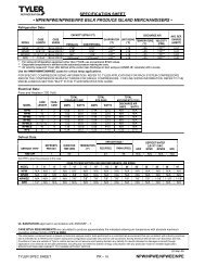
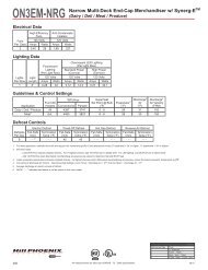
Energy Data<br />
6RZLH<br />
Electrical Data<br />
Doors<br />
Fans<br />
Per Case<br />
Light<strong>in</strong>g Data<br />
High Efficiency<br />
Fans<br />
Defrost Heaters<br />
1-Phase 3-Phase 1<br />
120 Volts 208 Volts 240 Volts 208 Volts 240 Volts<br />
Amps Watts Amps Watts Amps Watts Amps 2 Watts Amps 2 Watts<br />
2-<strong>door</strong> 3 0.47 27 10.99 2286 12.66 3038 7.61 2286 8.76 3038<br />
3-<strong>door</strong> 4 0.62 36 12.40 2580 14.27 3425 8.59 2580 9.88 3425<br />
4-<strong>door</strong> 6 0.93 54 16.29 3388 18.89 4533 11.28 3388 13.08 4533<br />
5-<strong>door</strong> 8 1.24 72 19.89 4138 22.93 5503 13.78 4138 15.88 5503<br />
Doors<br />
Anti-Condensate Heater Data<br />
Doors<br />
Anthony<br />
101 Elim<strong>in</strong>aator 5 Elim<strong>in</strong>aator 2 5<br />
120 Volts 120 Volts 120 Volts<br />
Amps Watts Amps Watts Amps Watts<br />
2-<strong>door</strong> 4.40 528 1.86 223 1.28 153<br />
3-<strong>door</strong> 6.15 738 2.77 332 1.89 227<br />
4-<strong>door</strong> 7.99 958 3.63 435 2.46 295<br />
5-<strong>door</strong> 9.90 1188 4.57 548 3.11 373<br />
Guidel<strong>in</strong>es & Control Sett<strong>in</strong>gs<br />
Application<br />
Defrost Controls<br />
Defrosts<br />
Per Day<br />
Run-Off<br />
Time (m<strong>in</strong>)<br />
Electric Defrost Timed-Off Defrost Hot Gas Defrost Reverse Air Defrost<br />
Fail-Safe<br />
(m<strong>in</strong>)<br />
Term<strong>in</strong>ation<br />
Temp (°F)<br />
Fail-Safe<br />
(m<strong>in</strong>)<br />
Term<strong>in</strong>ation<br />
Temp (°F)<br />
Fail-Safe<br />
(m<strong>in</strong>)<br />
Term<strong>in</strong>ation<br />
Temp (°F)<br />
Fail-Safe<br />
(m<strong>in</strong>)<br />
Term<strong>in</strong>ation<br />
Temp (°F)<br />
1 13 - 15 46 73 7 - - - - - - 24 73 8 - - - - - -<br />
1 3-phase load is unbalanced.<br />
LED Light<strong>in</strong>g<br />
Optimax Pro 3 GE IMMERSION Crossfire/Polaris 3<br />
120 Volts BTUH 120 Volts BTUH 120 Volts BTUH<br />
Amps Watts Credit Amps Watts Credit Amps Watts Credit<br />
2-<strong>door</strong> 0.36 43 205 0.33 39 210 - - - 4 - - - - - -<br />
3-<strong>door</strong> 0.53 64 177 0.48 58 182 - - - - - - - - -<br />
4-<strong>door</strong> 0.71 85 163 0.64 77 168 - - - - - - - - -<br />
5-<strong>door</strong> 0.88 106 154 0.80 96 159 - - - - - - - - -<br />
Door<br />
2 Figure given is maximum amps per phase.<br />
3 Low-power lights. High-power option available.<br />
4 NOTE: "- - -" not an option on this case model.<br />
5 Values provided are for <strong>door</strong>s with no heat on the glass.<br />
6 Average discharge air velocity at peak of defrost.<br />
BTUH/<strong>door</strong><br />
Conventional<br />
Parallel<br />
Evaporator<br />
(°F)<br />
Superheat<br />
Set Po<strong>in</strong>t @ Bulb<br />
(°F)<br />
Discharge<br />
Air<br />
(°F)<br />
7 The recommended location is <strong>in</strong> the center of the coil on the second pass. If us<strong>in</strong>g a discharge air temperature to term<strong>in</strong>ate defrost, utilize a 55ºF term<strong>in</strong>ation temp.<br />
8 The recommended location is on the dump l<strong>in</strong>e. If us<strong>in</strong>g a discharge air temperature to term<strong>in</strong>ate defrost, utilize a 55ºF term<strong>in</strong>ation temp.<br />
Discharge 6<br />
Air Velocity<br />
(FPM)<br />
Frozen Standard 1476 1434 -11 3 - 5 -4 350<br />
Elim<strong>in</strong>aator/Polar LE 1295 1258 -11 3-5 -4 350<br />
Ice Cream Standard 1579 1534 -17 3-5 -10 350<br />
Elim<strong>in</strong>aator/Polar LE 1398 1358 -17 3-5 -10 350<br />
2
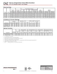
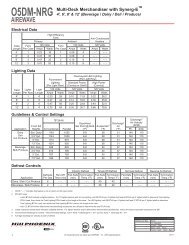
Case Dimensions<br />
43 3/8 <strong>in</strong> [110.1 cm]<br />
27"<br />
27"<br />
6RZLH<br />
Base Frame Structure<br />
Case<br />
Length Doors A B C D E<br />
60" 2 3/8" 28"* 55 1/2"<br />
90" 3 3/8" 28" 58" 85 1/2"<br />
120" 4 3/8" 28" 58"* 88" 115 1/2"<br />
150" 5 3/8" 28" 88" 118" 145 1/2"<br />
* Riser Support<br />
27"<br />
87 7/8 <strong>in</strong><br />
[223.3 cm]<br />
27"<br />
27"<br />
70 <strong>in</strong><br />
[177.8 cm]<br />
71 <strong>in</strong><br />
[180.2 cm]<br />
73 <strong>in</strong><br />
[185.4 cm]<br />
27"<br />
4 1/8 <strong>in</strong><br />
[10.5 cm]<br />
COIL<br />
PLENUM<br />
14 7/8 <strong>in</strong><br />
[37.8 cm]<br />
31 1/8 <strong>in</strong> [79.1 cm]<br />
40 1/2 <strong>in</strong> [103.0 cm]<br />
43 3/8 <strong>in</strong> [110.1 cm]<br />
3/8 <strong>in</strong> [1.1 cm]<br />
58 <strong>in</strong> [147.3 cm]<br />
28 <strong>in</strong> [71.1 cm]<br />
115 1/2 <strong>in</strong> [293.5 cm]<br />
88 <strong>in</strong> [223.5 cm]<br />
PIPING TO<br />
THE TOP<br />
(OPTIONAL)<br />
43 3/8 <strong>in</strong><br />
[110.1 cm] BASE FRAME<br />
40 1/2 <strong>in</strong><br />
[102.9 cm]<br />
31 7/8 <strong>in</strong><br />
[80.9 cm]<br />
WIRING TO<br />
THE TOP<br />
(OPTIONAL)<br />
28 3/8 <strong>in</strong><br />
[72.0 cm]<br />
30 1/4 <strong>in</strong><br />
[76.9 cm]<br />
ELECTRICAL<br />
JUNCTION BOX<br />
(WIRING PER LOCAL CODES)<br />
NOTES:<br />
2 DOOR CASE<br />
ONLY<br />
LC<br />
1 1/2" PVC DRAIN<br />
CONNECTION<br />
60 <strong>in</strong> [152.4 cm] ( 2 DOOR )<br />
90 <strong>in</strong> [228.6 cm] ( 3 DOOR )<br />
120 <strong>in</strong> [304.8 cm] ( 4 DOOR )<br />
150 <strong>in</strong> [381.0 cm] ( 5 DOOR )<br />
RISER<br />
REFRIGERATION<br />
KICK PLATE<br />
LOCATION<br />
8 3/4 <strong>in</strong><br />
[22.2 cm]<br />
* : STUB-UP AREA<br />
** : RECOMMENDED STUP-UP CENTERLINE FOR ELECTRICAL AND HUB DRAINS<br />
ENDS ADD APPROXIMATELY 1" TO CASE HEIGHT<br />
A 2" MINIMUM AIR GAP IS REQUIRED BETWEEN THE REAR OF THE CASE AND A WALL<br />
SUCTION LINE (ALL LENGTHS) - 1/2"<br />
LIQUID LINE (ALL LENGTHS) - 3/8", LIQUID LINE w/HOT GAS DEFROST (ALL LENGTHS) - 1/2"<br />
AVAILABLE SHELF SIZES: WIRE SHELVES 16", 18", 20", 22" & 23 1/2"<br />
SOLID SHELVES 18", 20", 22", 24, & 27"<br />
3
General Information<br />
Thank you for choos<strong>in</strong>g Hill PHOENIX for your food merchandis<strong>in</strong>g needs. This handbook conta<strong>in</strong>s important technical<br />
<strong>in</strong>formation and will assist you with the <strong>in</strong>stallation and operation of your new Hill PHOENIX display cases. By closely follow<strong>in</strong>g<br />
the <strong>in</strong>structions, you can expect peak performance; attractive fit and f<strong>in</strong>ish; and long case life.<br />
We are always <strong>in</strong>terested <strong>in</strong> your suggestions for improvements (e.g. case design, technical documents, etc.). Please feel<br />
free to contact our Market<strong>in</strong>g Services group at the toll-free number listed below. Thank you for choos<strong>in</strong>g Hill PHOENIX,<br />
and we wish you the very best <strong>in</strong> outstand<strong>in</strong>g food merchandis<strong>in</strong>g.<br />
CASE DESCRIPTION<br />
This manual covers the 6RZLH <strong>reach</strong>-<strong>in</strong> <strong>door</strong> <strong>merchandiser</strong>.<br />
STORE CONDITIONS<br />
Hill PHOENIX cases are designed to operate <strong>in</strong> an air-conditioned<br />
store that ma<strong>in</strong>ta<strong>in</strong>s a 75°F (24°C) store temperature<br />
and 55% (max) relative humidity (CRMA conditions).<br />
Case operation will be adversely affected by exposure to<br />
excessively high ambient temperatures and/or humidity.<br />
REFRIGERATION SYSTEM OPERATION<br />
Air-cooled condens<strong>in</strong>g units require adequate ventilation<br />
for efficient performance. Mach<strong>in</strong>e-room temperatures<br />
must be ma<strong>in</strong>ta<strong>in</strong>ed at a m<strong>in</strong>imum of 65°F <strong>in</strong> w<strong>in</strong>ter and a<br />
maximum of 95°F <strong>in</strong> summer. M<strong>in</strong>imum condens<strong>in</strong>g temperatures<br />
should be no less than 70°F.<br />
RECEIVING CASES<br />
Exam<strong>in</strong>e fixtures carefully and <strong>in</strong> the event of shipp<strong>in</strong>g<br />
damage and/or shortages, please contact the Service<br />
Parts Department at the toll-free number listed below.<br />
CASE DAMAGE<br />
Claims for obvious damage must be 1) noted on either the<br />
freight bill or the express receipt and 2) signed by the carrier's<br />
agent; otherwise, the carrier may refuse the claim. If<br />
damage becomes apparent after the equipment is<br />
unpacked, reta<strong>in</strong> all pack<strong>in</strong>g materials and submit a written<br />
request to the carrier for <strong>in</strong>spection with<strong>in</strong> 14 days of<br />
receipt of the equipment.<br />
LOST/MISSING ITEMS<br />
Equipment has been carefully <strong>in</strong>spected to <strong>in</strong>sure the highest<br />
level of quality. Any claim for lost/miss<strong>in</strong>g items must<br />
be made to Hill PHOENIX with<strong>in</strong> 48 hours of receipt of the<br />
equipment.<br />
TECHNICAL SUPPORT<br />
For technical questions regard<strong>in</strong>g display cases, please<br />
contact our Case Division Customer Service Department at<br />
the toll-free number listed below. For questions regard<strong>in</strong>g<br />
our refrigeration systems or electrical distribution centers,<br />
please contact our Systems Division Customer Service<br />
Department at 1-770-388-0706.<br />
CONTACTING THE FACTORY<br />
If you need to contact Hill PHOENIX regard<strong>in</strong>g a specific<br />
fixture, be certa<strong>in</strong> that you have both the case model number<br />
and serial number (this <strong>in</strong>formation can be found on<br />
the serial plate, located on the upper top flue panel on the<br />
right-hand side). When you have this <strong>in</strong>formation, call the<br />
toll-free number below and ask for a Service Parts<br />
Representative.<br />
HILL PHOENIX<br />
1925 Ruff<strong>in</strong> Mill Rd.<br />
Colonial Heights, VA 23834<br />
Mon.-Fri. (8 a.m to 5 p.m EST)<br />
Tel: 1-800-283-1109/Fax: 804-526-7450<br />
Web site: www.hillphoenix.com<br />
4
Installation<br />
MOVING CASES<br />
Hill PHOENIX display cases are generally shipped to<br />
stores with casters <strong>in</strong>stalled on the base frame. The casters<br />
make the job of mov<strong>in</strong>g cases easier for everyone<br />
<strong>in</strong>volved <strong>in</strong> the shipp<strong>in</strong>g and <strong>in</strong>stallation process, as well as<br />
reduc<strong>in</strong>g the chance of damage from rais<strong>in</strong>g and lower<strong>in</strong>g<br />
cases with ”J” bars to place them on dollies, skates or rollers.<br />
In most situations, one or two persons can easily<br />
move the case <strong>in</strong>to position.<br />
When the cases arrive at the store, simply roll them on to<br />
the store floor to the proper stag<strong>in</strong>g area. Occasionally,<br />
cases are shipped with skid boards attached to help with<br />
stabilization. In these <strong>in</strong>stances, the casters should be<br />
attached after the case is removed from the truck.<br />
Remov<strong>in</strong>g the casters is an easy process. Simply flatten<br />
and remove the cotter p<strong>in</strong>s that are hold<strong>in</strong>g the casters <strong>in</strong><br />
place (Fig. 1). Then lift the case with a “J” bar and slide<br />
the caster assemblies out. The dismantled casters can<br />
now be discarded.<br />
FLOOR PREP<br />
▲<br />
W A R N I N G<br />
Be certa<strong>in</strong> that your hands and feet are out of<br />
the way before lower<strong>in</strong>g the case after the<br />
removal of the casters. Failure to do so may<br />
result <strong>in</strong> serious <strong>in</strong>jury.<br />
1. Ask the general contractor if your current copy of the<br />
build<strong>in</strong>g dimensions are the most recently issued. Also,<br />
ask for the po<strong>in</strong>ts of reference from which you should<br />
take dimensions to locate the cases.<br />
2. Us<strong>in</strong>g chalk l<strong>in</strong>es or a laser transit, mark the floor<br />
where the cases are to be located for the entire l<strong>in</strong>eup.<br />
The l<strong>in</strong>es should co<strong>in</strong>cide with the outside edges of the<br />
case feet.<br />
3. Level<strong>in</strong>g is necessary to ensure proper case alignment<br />
and to avoid potential case damage. Locate the<br />
highest po<strong>in</strong>t on the position<strong>in</strong>g l<strong>in</strong>es as a reference for<br />
determ<strong>in</strong><strong>in</strong>g the proper height of the shim-pack levelers.<br />
A laser transit is recommended for precision and<br />
requires just one person.<br />
4. Locate basehorse positions along the chalk l<strong>in</strong>e. Spot<br />
properly leveled shim packs at each basehorse location.<br />
LINE-UP & INSTALLATION<br />
S<strong>in</strong>gle Case<br />
<br />
1. Roll the case <strong>in</strong>to position, leav<strong>in</strong>g a m<strong>in</strong>imum of 2" between<br />
the wall and back of case. Us<strong>in</strong>g a “J” bar , raise<br />
Fig. 1 Caster assembly<br />
J-BAR<br />
CASTER<br />
the end of the case (under cross support), remove the<br />
caster assembly and lower the basehorse on to the<br />
shim packs. Repeat on the other end of the case.<br />
2. Once the basehorse is properly placed on the shim<br />
packs, check the vertical plumb of the case by plac<strong>in</strong>g<br />
a bubble level on the rear wall. Add/remove shim<br />
packs as needed. To check the horizontal level, repeat<br />
this process after plac<strong>in</strong>g the bubble level on the front<br />
sill.<br />
Multi-Case<br />
1. Remove any loose items from the cases that may<br />
<strong>in</strong>terfere with case jo<strong>in</strong><strong>in</strong>g (e.g. shipp<strong>in</strong>g braces, mirror<br />
assemblies, etc). Be certa<strong>in</strong> to keep all loose items<br />
close to the case <strong>in</strong> which they shipped as they will<br />
be used later <strong>in</strong> the <strong>in</strong>stallation process.<br />
2. Remove the return air grill at the case jo<strong>in</strong>t. The grill<br />
lifts out without fasteners and may be easily removed<br />
to ga<strong>in</strong> clear access to the case-to-case jo<strong>in</strong><strong>in</strong>g bolts.<br />
3. Follow the s<strong>in</strong>gle-case <strong>in</strong>stallation <strong>in</strong>structions (above)<br />
for the first case, then position the next case <strong>in</strong> the l<strong>in</strong>eup<br />
approximately 3’ away. Remove the casters on the<br />
end that is closest to the first case.<br />
4. Apply the foam tape gasket (supplied) and a bead of<br />
butyl or silicone sealant to the end breaker of the first<br />
case (Fig. 2). From the opposite end, push the second<br />
case to a position that is approximately 6" from the first<br />
case, then remove the rema<strong>in</strong><strong>in</strong>g casters and position<br />
case on the shim packs.<br />
5. Push the cases tightly together, then lightly bolt them<br />
together through the holes that are provided (Fig. 2).<br />
Tighten all the jo<strong>in</strong><strong>in</strong>g bolts until all marg<strong>in</strong>s are equal.<br />
Be careful not to over tighten.<br />
6. Repeat steps 2-6 of this sequence for all rema<strong>in</strong><strong>in</strong>g<br />
cases. Be certa<strong>in</strong> to properly level all cases.<br />
5
XXXXXXXXXXXXXXXXXXXXXXXXXXXXXXXXXXXXXXXXXXXXXX<br />
Installation<br />
TRIM OUT<br />
1. Seal the case-to-case jo<strong>in</strong>ts with caulk (supplied), then<br />
apply acrylic tape (supplied) over the pipe-chase seam<br />
(Fig. 3). The tape acts as a watershed prevent<strong>in</strong>g water<br />
from settl<strong>in</strong>g <strong>in</strong> the case jo<strong>in</strong>t.<br />
2. Make any adjustments that are necessary to properly<br />
align the front panels, then <strong>in</strong>stall the front panel trim<br />
(supplied).<br />
3. Install the front panel (Fig. 4). The front panel bottom<br />
<strong>in</strong>sert is a pa<strong>in</strong>ted panel that ships loose with the case.<br />
The panel is <strong>in</strong>serted upward under the <strong>door</strong> frame<br />
exteriors and is supported without fasteners by sett<strong>in</strong>g<br />
the panel on the tabs as shown.<br />
4. Install the front kickplate (Fig. 5) to the kickplate reta<strong>in</strong>er<br />
as shown.<br />
PIPE<br />
CHASE<br />
Fig. 3 Seal<strong>in</strong>g the pipe chase<br />
ACRYLIC<br />
TAPE<br />
FRONT PANEL<br />
(Top Insert)<br />
XXXXXXXXXXXXXXXXXXXXXXXXXXXXXXXXXXXXXXXXXXXXXXXXXXXXXXXXXXXXXXXXXXXXXXXXXXXXXXXXXXXXXXXXXXXXXXXXXX<br />
OOOOOOOOOOOOOOOOOOOOOOOOOOOOOOOOOOOOOOOOOOOO<br />
OOOOOOOOOOOOOOOOOOOOOOOOOOOOOOOOOOOOOOOOOOOOOOOOOOOOOOOOOOOOOOOOOOOOOOOOOOOOOOOOOOOOOOOOOOOOOOOOOOO<br />
OOO<br />
4<br />
1<br />
2<br />
3 5<br />
OOOOOO<br />
OOO<br />
OOOOOOOOOOOOOOOOOOOOOOOOOOOOOOOOOOOOOOOOOOOO<br />
OOOOOOOOOOOOOOOOOOOOOOOOOOOOOOOOOOOOOOOOOOOOO<br />
OOOOOOOOOOOOOOOOOO<br />
XXXXXXXXXXXXXXXXXXXXXXXXXXXXXXXXXXXXXXXXXXXXXXX<br />
Fig. 2 Bolt holes, foam tape gasket and sealant<br />
XXXXXXXXXXXXXXXXXXXXXXXXXXXXXXXXXXXXXXXXXXXXXXXXXXXXXXXXXXXXXXXXXXXXXXXXXXXXXXXXXXXXXXXXXXXXXXXXX<br />
OOOOOO<br />
Fig. 4 Install front panel<br />
KICKPLATE<br />
RETAINER<br />
FRONT PANEL<br />
(Bottom Insert)<br />
KICKPLATE<br />
Fig. 5 Attach kickplate with supplied screws<br />
= bolt holes<br />
X = foam tape gasket<br />
O = butyl or silicone sealant<br />
SCREWS<br />
NOTE: It is recommended that cases<br />
be bolted together <strong>in</strong> the numbered<br />
order <strong>in</strong>dicated <strong>in</strong> the diagram.<br />
6
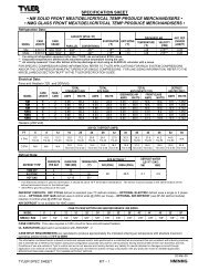
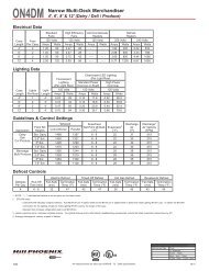
Case Connections<br />
REFRIGERATION<br />
As the diagram below <strong>in</strong>dicates, the pip<strong>in</strong>g penetration<br />
area is located at the front, right-hand side of the case, fully<br />
visible <strong>in</strong> front of the fan plenum. An optional pip<strong>in</strong>g to the<br />
top rear is provided with refrigeration pipes stubbed out and<br />
labelled at the top of the case. These pipes exit the case<br />
through the lower rear pipe egress and <strong>in</strong>to a foam-filled<br />
box. Refrigeration connections are made at the top of the<br />
case.<br />
The expansion valve and other controls - located on the<br />
left-hand side of the case - are accessible without lift<strong>in</strong>g<br />
the fan plenum and may be <strong>reach</strong>ed by lift<strong>in</strong>g the two deck<br />
pans.<br />
If it becomes necessary to penetrate the case bottom, be<br />
certa<strong>in</strong> to seal it afterwards with canned-foam sealant and<br />
white RTV.<br />
PLUMBING<br />
The dra<strong>in</strong> outlet is specially molded out of PVC material<br />
and is located <strong>in</strong> the front-center of the case for convenient<br />
access. The “P” trap, furnished with the case, is constructed<br />
of schedule 40 PVC pipe. Care should be given to<br />
ensure that all connections are water-tight and sealed with<br />
the appropriate PVC or ABS cement.<br />
The dra<strong>in</strong> l<strong>in</strong>es can be run left or right of the tee with the<br />
proper pitch to satisfy local dra<strong>in</strong>age requirements. S<strong>in</strong>ce<br />
the kickplate is shipped loose with the case, you should<br />
have open access to the dra<strong>in</strong> l<strong>in</strong>e area dur<strong>in</strong>g <strong>in</strong>stallation.<br />
Once the kickplate has been <strong>in</strong>stalled, you will f<strong>in</strong>d it very<br />
easy to remove. Simply lift the kickplate up from the "J" rail<br />
and pull it out, away from the case. See the Trim Out section<br />
on page 6.<br />
ELECTRICAL<br />
Electrical hookups are made to a junction box located<br />
either at the bottom-left-front of the case or the top-left-rear<br />
of the case. See the appendix section at the end of this<br />
manual for more detailed electrical wir<strong>in</strong>g <strong>in</strong>formation.<br />
For case-to-case wir<strong>in</strong>g, run conduit between the junction<br />
boxes or run wir<strong>in</strong>g through the raceway. When connect<strong>in</strong>g<br />
to the junction box on the bottom-left side of the case, field<br />
wir<strong>in</strong>g should exit box from the right side (furthest away<br />
from case wir<strong>in</strong>g) to allow more room <strong>in</strong>side for wir<strong>in</strong>g connections.<br />
MODEL<br />
6RZLH<br />
REMOVE<br />
3/8 <strong>in</strong> [1.1 cm]<br />
58 <strong>in</strong> [147.3 cm]<br />
28 <strong>in</strong> [71.1 cm]<br />
88 <strong>in</strong> [223.5 cm]<br />
115 1/2 <strong>in</strong> [293.5 cm]<br />
PIPING TO THE TOP<br />
(OPTIONAL)<br />
43 3/8 <strong>in</strong><br />
[110.1 cm] BASE FRAME<br />
40 1/2 <strong>in</strong><br />
[102.9 cm]<br />
31 7/8 <strong>in</strong><br />
[80.9 cm]<br />
WIRING TO<br />
THE TOP<br />
(OPTIONAL)<br />
28 3/8 <strong>in</strong><br />
[72.0 cm]<br />
30 1/4 <strong>in</strong><br />
[76.9 cm]<br />
REMOVE THE SHIPPING BLOCKS THAT PROTECT THE<br />
REFRIGERATION LINES DURING SHIPMENT BEFORE<br />
OPERATING THE CASE.<br />
ELECTRICAL<br />
JUNCTION BOX<br />
(WIRING PER LOCAL CODES)<br />
2 DOOR CASE<br />
ONLY<br />
1 1/2" PVC DRAIN<br />
CONNECTION<br />
LC<br />
60 <strong>in</strong> [152.4 cm] ( 2 DOOR )<br />
90 <strong>in</strong> [228.6 cm] ( 3 DOOR )<br />
120 <strong>in</strong> [304.8 cm] ( 4 DOOR )<br />
150 <strong>in</strong> [381.0 cm] ( 5 DOOR )<br />
RISER<br />
REFRIGERATION<br />
KICK PLATE<br />
LOCATION<br />
8 3/4 <strong>in</strong><br />
[22.2 cm]<br />
▲<br />
<br />
C A U T I O N<br />
If any braz<strong>in</strong>g is necessary, place wet rags<br />
around the area to avoid tank damage.<br />
7
Ballasts Access<br />
The electronic ballasts that operate the vertical prism <strong>door</strong> lights are located <strong>in</strong> the <strong>door</strong> frame for<br />
Anthony ® <strong>door</strong> frames.<br />
ANTHONY ® FRAMES<br />
MULLION<br />
LIGHT<br />
3. BALLAST<br />
1. CORNER BEAD<br />
1. CORNER BEAD<br />
2. ACCESS COVER<br />
DOOR<br />
STEPS TO REPLACE THE BALLAST<br />
ANTHONY ® FRAMES<br />
1. REMOVE CORNER BEADS (2)<br />
2. REMOVE ACCESS COVER<br />
3. REPLACE BALLAST<br />
8
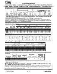
Airflow, Defrost & Temp Controls<br />
AIR FLOW & PRODUCT LOAD<br />
Hill PHOENIX cases provide maximum product capacity<br />
with<strong>in</strong> the refrigerated air envelope. Please keep products<br />
with<strong>in</strong> the load limit l<strong>in</strong>e shown on the diagram below.<br />
It is important that you do not overload the food product display<br />
so that it imp<strong>in</strong>ges on the air flow pattern. Overload<strong>in</strong>g<br />
will cause malfunction and the loss of proper temperature<br />
levels, particularly when discharge and return air sections<br />
are covered.<br />
DEFROST & TEMPERATURE CONTROLS<br />
6RZLH cases are equipped with either Electric or Hot Gas<br />
defrost as specified by the customer. For both modes of<br />
defrost, either a defrost term<strong>in</strong>ation bi-metal disc thermostat<br />
(Klixon) or a probe are utilized.<br />
1. Discharge Air<br />
2. Air Flow<br />
3. Load Limit<br />
4. Return Air<br />
1<br />
2<br />
3<br />
4<br />
The Klixon is <strong>in</strong>stalled on the coil and is used to term<strong>in</strong>ate<br />
the defrost cycle when the Klixon contact opens at the set<br />
temperature. If a probe is used then, the operation is similar<br />
to that of defrost term<strong>in</strong>ation.<br />
Electric defrost is accomplished us<strong>in</strong>g two defrost heaters<br />
mounted directly onto the coil - one <strong>in</strong> the rear and one <strong>in</strong><br />
the front. An additional supplemental dra<strong>in</strong> heater is mounted<br />
between the dra<strong>in</strong> and the fan plenum. The three heaters<br />
are powered by a 3-phase 208V connection to the<br />
case at L1/L2/L3 (see Wir<strong>in</strong>g Diagrams).<br />
Several devices are used to properly control an optimal<br />
defrost cycle. Additional components are used to signal<br />
that defrost term<strong>in</strong>ation temperature has been <strong>reach</strong>ed for<br />
a particular case that is on a shared defrost power circuit.<br />
Fan Time Delay<br />
The time delay relay <strong>in</strong> the defrost control system is a ON<br />
DELAY type. This time delay is <strong>in</strong>itiated by the application<br />
of an <strong>in</strong>put voltage - no external trigger is required. The<br />
<strong>in</strong>put voltage for this application is supplied by two legs (L1<br />
and L2) of the 3-phase defrost power. When the defrost<br />
voltage to the case is applied, the preset time beg<strong>in</strong>s. At<br />
the end of the preset time, the relay contacts will transfer<br />
from the NC to the NO contact, stopp<strong>in</strong>g fan operation.<br />
Defrost Term<strong>in</strong>ation Thermostat<br />
A bimetal disc thermostat attached to the top center of the<br />
evaporator coil is used to signal that the coil has been fully<br />
defrosted. The thermostat contact opens at 73°F (60°F for<br />
CO 2<br />
cases), cutt<strong>in</strong>g defrost power to the case. The thermostat<br />
contact closes when the sens<strong>in</strong>g temperature drops<br />
below 28°F. This will allow for the next defrost cycle to cont<strong>in</strong>ue<br />
as scheduled.<br />
Defrost Term<strong>in</strong>ation Cascade<br />
Each case <strong>in</strong> a refrigeration/defrost circuit has the ability to<br />
term<strong>in</strong>ate electrical defrost based on <strong>in</strong>dividual case conditions.<br />
For <strong>in</strong>stance, when electrical defrost beg<strong>in</strong>s on a<br />
case l<strong>in</strong>eup that <strong>in</strong>cludes a one 4-<strong>door</strong> case and two<br />
5-<strong>door</strong> cases, it is possible for the coil <strong>in</strong> the 4-<strong>door</strong> case to<br />
be fully defrosted and <strong>reach</strong> defrost term<strong>in</strong>ation temperature<br />
before the larger cases <strong>in</strong> the same circuit. With proper<br />
setup, the defrost can stop <strong>in</strong> the cleared case and<br />
cont<strong>in</strong>ue <strong>in</strong> the other cases until defrost term<strong>in</strong>ation temperature<br />
is <strong>reach</strong>ed. The system allows a dry contact digital<br />
output to be sent to the rack controls signal<strong>in</strong>g that<br />
defrost has been completed <strong>in</strong> the case l<strong>in</strong>eup.<br />
Fig. 6 Case airflow.<br />
9
Use & Ma<strong>in</strong>tenance<br />
CLEANING PROCEDURES<br />
• A periodic clean<strong>in</strong>g schedule should be established to<br />
ma<strong>in</strong>ta<strong>in</strong> proper sanitation, <strong>in</strong>sure maximum operat<strong>in</strong>g<br />
efficiency, and avoid the corrosive action of food fluids<br />
on metal parts that are left on for long periods of time.<br />
We recommend clean<strong>in</strong>g once a week.<br />
• To avoid shock hazard, be sure all electrical power is<br />
turned off before clean<strong>in</strong>g. In some <strong>in</strong>stallations, more<br />
than one disconnect switch may have to be turned off<br />
to completely de-energize the case.<br />
• All surfaces pitch downward to a deep-drawn dra<strong>in</strong><br />
trough, funnel<strong>in</strong>g liquids/ to the front of the case where<br />
the waste outlet is located for easy access. Check<br />
waste outlet to <strong>in</strong>sure it is not clogged before start<strong>in</strong>g<br />
the clean<strong>in</strong>g process and avoid <strong>in</strong>troduc<strong>in</strong>g water faster<br />
than the case dra<strong>in</strong> can carry it away.<br />
• To clean the LED lum<strong>in</strong>aires, shut off the lights <strong>in</strong> the<br />
case, then wipe the lum<strong>in</strong>aires down with a soft, damp<br />
cloth. Avoid us<strong>in</strong>g harsh or abrasive cleaners as they<br />
may damage the lights. Be certa<strong>in</strong> that the lum<strong>in</strong>aires<br />
are completely dry before re-energiz<strong>in</strong>g.<br />
• If any potentially harmful cleaners are used, be certa<strong>in</strong><br />
to provide a temporary separator (e.g., cardboard,<br />
plastic rap, etc.) between those cases that are be<strong>in</strong>g<br />
cleaned and those that may still conta<strong>in</strong> product.<br />
• Avoid spray<strong>in</strong>g clean<strong>in</strong>g solutions directly on electrical<br />
connections.<br />
• Allow cases to be turned off long enough to clean any<br />
frost or ice from coil and pans.<br />
• Remove kickplate and clean underneath the case with<br />
a broom and a long-handled mop. Use warm water<br />
and a dis<strong>in</strong>fect<strong>in</strong>g clean<strong>in</strong>g solution when clean<strong>in</strong>g<br />
underneath the cases.<br />
▲ D A N G E R<br />
<br />
SHOCK HAZARD<br />
Always disconnect power to case when servic<strong>in</strong>g<br />
or clean<strong>in</strong>g. Failure to do so may result <strong>in</strong><br />
serious <strong>in</strong>jury or death.<br />
37 37<br />
FANS<br />
The evaporator fans are equipped with 16-watt fan motors.<br />
Motors have a counter-clockwise rotation when viewed<br />
from the shaft end.<br />
The fan blades are 8” <strong>in</strong> diameter with a 31o fan blade<br />
pitch. It is important that the blade pitch be ma<strong>in</strong>ta<strong>in</strong>ed as<br />
<strong>in</strong>stalled. Do not attempt a field modification by alter<strong>in</strong>g<br />
the blades.<br />
Fan motors may be changed with an easy two-step process<br />
without lift<strong>in</strong>g up the plenum, thereby avoid<strong>in</strong>g the<br />
necessity to unload the entire product display to make a<br />
change:<br />
1. Unplug the fan motor, easily accessible outside the<br />
plenum. Push power cord back through plenum<br />
open<strong>in</strong>g.<br />
2. Remove two fasteners, then lift out the entire fan<br />
basket.<br />
Reverse procedure when re-<strong>in</strong>stall<strong>in</strong>g fan basket.<br />
2<br />
1<br />
FAN ASSEMBLY<br />
<br />
▲W A R N I N G<br />
Exercise extreme caution when work<strong>in</strong>g <strong>in</strong> a<br />
37<br />
case with the coil cover removed. The coil<br />
conta<strong>in</strong>s many sharp edges that can result <strong>in</strong><br />
severe cuts to the hands and arms.<br />
37 37<br />
37 37<br />
37 37<br />
10<br />
COIL<br />
PLENUM<br />
SINGLE PIECE FAN PLENUM LIFTS UP<br />
FOR EASY ACCESS AND CLEANING
Parts Order<strong>in</strong>g<br />
Contact the Service Parts Department at:<br />
1-800-283-1109<br />
Provide the follow<strong>in</strong>g <strong>in</strong>formation about the part you are<br />
order<strong>in</strong>g:<br />
• Model number and serial number of the case for<br />
which the part is <strong>in</strong>tended.<br />
• Length of the part (if applicable).<br />
• Color of part (if pa<strong>in</strong>ted) or color of polymer part.<br />
• Whether part is for left- or right-hand application.<br />
• Quantity<br />
*Serial plate is located on the back of the case on the left-hand side.<br />
If the parts are to be returned for credit, ask the Parts<br />
Department to furnish you with a Return Material<br />
Authorization Number.<br />
11
Appendix A:<br />
Wir<strong>in</strong>g Diagrams
NOTES
NOTES
NOTES
WARRANTY<br />
HEREINAFTER REFERRED TO AS MANUFACTURER<br />
FOURTEEN MONTH WARRANTY. MANUFACTURER’S PRODUCT IS WARRANTED TO BE FREE FROM DEFECTS<br />
IN MATERIAL AND WORKMANSHIP UNDER NORMAL USE AND MAINTENANCE FOR A PERIOD OF FOURTEEN<br />
MONTHS FROM THE DATE OF ORIGINAL SHIPMENT. A NEW OR REBUILT PART TO REPLACE ANY<br />
DEFECTIVE PART WILL BE PROVIDED WITHOUT CHARGE, PROVIDED THE DEFECTIVE PART IS RETURNED TO<br />
MANUFACTURER. THE REPLACEMENT PART ASSUMES THE UNUSED PORTION OF THE WARRANTY.<br />
This warranty does not <strong>in</strong>clude labor or other costs <strong>in</strong>curred for repair<strong>in</strong>g, remov<strong>in</strong>g, <strong>in</strong>stall<strong>in</strong>g, shipp<strong>in</strong>g, servic<strong>in</strong>g, or<br />
handl<strong>in</strong>g of either defective parts or replacement parts.<br />
The fourteen month warranty shall not apply:<br />
1. To any unit or any part thereof which has been subject to accident, alteration, negligence, misuse or<br />
abuse, operation on improper voltage, or which has not been operated <strong>in</strong> accordance with the<br />
manufacturer’s recommendation, or if the serial number of the unit has been altered, defaced, or removed.<br />
2. When the unit, or any part thereof, is damaged by fire, flood, or other act of God.<br />
3. Outside the cont<strong>in</strong>ental United States.<br />
4. To labor cost for replacement of parts, or for freight, shipp<strong>in</strong>g expenses, sales tax or upgrad<strong>in</strong>g.<br />
5. When the operation is impaired due to improper <strong>in</strong>stallation.<br />
6. When <strong>in</strong>stallation and startup forms are not properly complete or returned with<strong>in</strong> two weeks after startup.<br />
THIS PLAN DOES NOT COVER CONSEQUENTIAL DAMAGES. Manufacturer shall not be liable under any circumstances<br />
for any consequential damages, <strong>in</strong>clud<strong>in</strong>g loss of profit, additional labor cost, loss of refrigerant or food products,<br />
or <strong>in</strong>jury to personnel or property caused by defective material or parts or for any delay <strong>in</strong> its performance hereunder<br />
due to causes beyond its control. The forego<strong>in</strong>g shall constitute the sole and exclusive remedy of any purchases<br />
and the sole and exclusive liability of Manufacturer <strong>in</strong> connection with this product.<br />
The Warranties are Expressly <strong>in</strong> Lieu of All Other Warranties, Express of Implied and All Other Obligations or<br />
Liabilities on Our Part. The Obligation to Repair or Replace Parts or Components Judged to be Defective <strong>in</strong><br />
Material or Workmanship States Our Entire Liability Whether Based on Tort, Contract or Warranty. We Neither<br />
Assume Nor Authorize Any Other Person to Assume for Us Any Other Liability <strong>in</strong> Connection with Our Product.<br />
MAIL CLAIM TO:<br />
Hill PHOENIX<br />
Display Merchandisers<br />
1925 Ruff<strong>in</strong> Mill Road<br />
Colonial Heights, VA 23834<br />
1-800-283-1109<br />
Hill PHOENIX<br />
Refrigeration Systems &<br />
Electrical Distribution Products<br />
709 Sigman Road<br />
Conyers, GA 30013<br />
770-285-3200<br />
06/00
Warn<strong>in</strong>g<br />
Ma<strong>in</strong>tenance & Case Care<br />
When clean<strong>in</strong>g cases the follow<strong>in</strong>g must be performed<br />
PRIOR to clean<strong>in</strong>g:<br />
To avoid electrical shock, be sure all electric power is<br />
turned off before clean<strong>in</strong>g. In some <strong>in</strong>stallations, more<br />
than one switch may have to be turned off to completely<br />
de-energize the case.<br />
Do not spray clean<strong>in</strong>g solution or water directly on fan<br />
motors or any electrical connections.<br />
All light<strong>in</strong>g receptacles must be dried off prior to <strong>in</strong>sertion<br />
and re-energiz<strong>in</strong>g the light<strong>in</strong>g circuit.<br />
Please refer to the Use and Ma<strong>in</strong>tenance section of this <strong>in</strong>stallation manual.<br />
Tel: 1-800-283-1109<br />
1925 Ruff<strong>in</strong> Mill Road, Colonial Heights, VA 23834<br />
Due to our commitment to cont<strong>in</strong>uous improvement, all specifications are subject to change without notice.<br />
Hill PHOENIX is a Susta<strong>in</strong><strong>in</strong>g Member of the American Society of Quality.<br />
Visit our web site at www.hillphoenix.com<br />
BDM0711