AES-302 Digital Audio Switcher - Broadcast Devices, Inc.
AES-302 Digital Audio Switcher - Broadcast Devices, Inc.
AES-302 Digital Audio Switcher - Broadcast Devices, Inc.

Create successful ePaper yourself
Turn your PDF publications into a flip-book with our unique Google optimized e-Paper software.
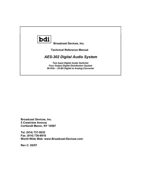
<strong>Broadcast</strong> <strong>Devices</strong>, <strong>Inc</strong>.<br />
Technical Reference Manual<br />
<strong>AES</strong>-<strong>302</strong> <strong>Digital</strong> <strong>Audio</strong> System<br />
Two Input <strong>Digital</strong> <strong>Audio</strong> <strong>Switcher</strong><br />
Four Output <strong>Digital</strong> Distribution System<br />
96 KHz – 24 Bit <strong>Digital</strong> to Analog Converter<br />
<strong>Broadcast</strong> <strong>Devices</strong>, <strong>Inc</strong>.<br />
5 Crestview Avenue<br />
Cortlandt Manor, NY 10567<br />
Tel. (914) 737-5032<br />
Fax. (914) 736-6916<br />
World Wide Web: www.<strong>Broadcast</strong>-<strong>Devices</strong>.com<br />
Rev C. 02/07
2<br />
Table of Contents<br />
I. Introduction 3<br />
II. Unpacking 3<br />
III. Installation and Connections 3<br />
IV. Features and Operation 3<br />
V. Initial Operations Setup 4<br />
Theory of Operation – <strong>Digital</strong> <strong>Switcher</strong> 5<br />
Error Switching Table 1. 5<br />
Silence Sensor Setup Table 2. 5<br />
Remote Control Pin out Table 3. 6<br />
VI. Specifications 7<br />
VII. Warranty 8<br />
VIII. Schematic Diagrams 9-12
3<br />
I. Introduction<br />
The <strong>AES</strong>-<strong>302</strong> <strong>Digital</strong> <strong>Audio</strong> System comprises of a two input <strong>AES</strong> compatible switcher, four output<br />
digital audio DA and digital to analog converter. The unit also has status and diagnostic error indicators for<br />
troubleshooting. The <strong>AES</strong>-<strong>302</strong> is intended for use at unattended transmitter sites or for virtually any digital<br />
switching, distribution and/or D/A conversion application. The unit has the capability to automatically<br />
switch inputs upon detection of loss of clock, digital error flags and/or silence sense. In addition to these<br />
features, the unit can function as an interface standards converter. As shipped from the factory the unit is<br />
supplied with XLR balanced connectors. The unit can be configured with any combination of input/output<br />
connectors if desired. Default factory supplied connections are XLR. Optical and S.P.D.I.F – RCA<br />
connections are available as options.<br />
II. Unpacking and Inspection<br />
Carefully inspect the unit after unpacking and make certain that no damage has occurred during shipping.<br />
If damage is noted, contact the shipper immediately and file a claim for damages. Each unit is carefully<br />
packed and carries full insurance against damage. Inspect the packing list and make sure that the contents<br />
of the package match those described on the packing list.<br />
III. Installation and Connections<br />
Select a space in suitable E.I.A. standard rack to locate the unit. Determine the local electrical power<br />
supply voltage and select the proper input voltage at the rear of the unit. As supplied from the factory, your<br />
<strong>AES</strong>-<strong>302</strong> is setup for 120 V.A.C. 60 Hz unless noted otherwise. To change the input voltage to 240 volts,<br />
simply slide the plastic cover and remove the p.c. board in the E.M.I. protected power entry module and<br />
flip it so that “240 Volts” is legible from the rear as the board is placed back into the power entry module.<br />
No replacement of the fuse is necessary as the fuse supplied is rated for up to 250 V.A.C. operation. The<br />
unit is rated to run from 120/240 V.A.C. at 50 to 60 Hz operation. Make connections to the unit following<br />
good engineering practice. Supply power to the unit utilizing a three pronged grounded outlet. Do no lift<br />
the electrical ground to the unit at the power receptacle as this will result in a safety hazard. In the event of<br />
ground loops, lift the ground at the offending connection only. Make certain that the unit is afforded proper<br />
ventilation in the area of the top cover vent.<br />
A. <strong>Digital</strong> Interface<br />
Unless ordered as an option Inputs to the switcher are balanced XLR connectors conforming to the <strong>AES</strong><br />
standard. The unit may be ordered with SPDIF or optical interface. Each XLR connection is terminated at<br />
110 ohms as per the standard. SPDIF inputs are terminated at 75 0hms. The balanced digital outputs are<br />
also XLR connections, which provide 110-ohm transformer coupled source impedance as per the standard.<br />
Again as an option outputs can be configured for SPDIF or optical interface.<br />
B. Analog Interface<br />
There is provided on the rear of the unit a left/right balanced analog output. This output is suitable for<br />
driving 600-ohm balanced lines and is short circuit protected. A headphone jack and volume control<br />
buttons are provided on the front panel of the unit for confidence monitoring of the incoming feed.<br />
IV. Features and Operation<br />
The <strong>AES</strong>-<strong>302</strong> <strong>Digital</strong> <strong>Audio</strong> System is designed to select one of two <strong>AES</strong>3 compatible feeds and route it to<br />
up to four balanced, optical or unbalanced digital loads. It also contains a high quality digital to analog
4<br />
converter providing a balanced left and right output. The unit features a front panel headphone output and<br />
volume control for easy confidence monitoring. The <strong>AES</strong>-<strong>302</strong> can be used as a totally automatic switcher<br />
sensing loss of clock or any error displayed on the front panel to command the switcher to select the<br />
alternate feed. In addition to digital error switching, the unit features a silence sense circuit for switching<br />
upon audio failure conditions. All automatic switching functions are user defined and can be initialized<br />
with a simple DIP switch setting upon installation of the unit. Command of the switcher can also be<br />
performed manually at the front panel or remotely.<br />
Remote control of the unit is accessed through the rear panel 9 pin D connector. Simple momentary ground<br />
closure to the appropriate pin selects channels and error reset. Status of channel selected and error flag is<br />
also available at this connector. Refer to the pin out table 3 on page 6 for connection information. The<br />
interface is compatible with open collector command. The <strong>AES</strong>-<strong>302</strong> supplies +15 V.D.C. for powering<br />
open collector actuators.<br />
Two additional features that have been added to later production <strong>AES</strong>-<strong>302</strong> units includes power fail feed<br />
through of the selected input to <strong>AES</strong> output #1 and a delay circuit has been added to the automatic<br />
switching function. With no power connected to the unit, the <strong>AES</strong>-<strong>302</strong> will pass the last selected input<br />
signal to the #1 <strong>AES</strong> output through K3 NC contacts. Upon power application K3 energizes and <strong>AES</strong> #1<br />
output receives its signal from U2 RS-485 driver. The additional delay was added to prevent the unit from<br />
switching on momentary glitches that can occur in STL equipment. An added 3 seconds to the switching<br />
time prevents the unit from switching under transient conditions.<br />
V. Initial Operating Set up<br />
Attach input and output connections to the unit using the appropriate connector. The unit can be supplied<br />
with XLR, S.P.D.I.F., or optical connectors at any of the inputs or outputs. If the connector scheme<br />
supplied is not the one desired, consult the factory for a field or factory connector modification.<br />
Plug the remote control plug in and tighten the connector screws in place.<br />
You may select any or all of the error flag and/or silence sense switching, which will command the<br />
switcher to switch to the alternate path. The “no lock” position S6-2 is always selected for automatic<br />
operation. Other error flags and the silence sense error are selected by placing the designated DIP switches<br />
to the on position. Refer to the theory of operation section table 1 on page 5 for possible settings. Once<br />
this is done, the unit is ready to be powered up for operation. The default setting is to command the<br />
switcher upon loss of clock. When the silence sense error is selected for switching, there are several<br />
configurations possible. It is possible to monitor both left and right channels and switch upon complete<br />
audio loss or to have the silence sensor switch upon loss of left or right channel individually. This feature<br />
was added so that non correlated audio feeds can cause the silence sensor to switch where one feed may<br />
take precedence over another. Selection of L+R, Left, or Right only audio is done by placing the proper<br />
jumpers on the motherboard. Refer to the theory of operation section table 2 on page 5 for the various<br />
settings.<br />
Once power is applied and a valid <strong>AES</strong> bit stream is applied to the selected input, the unit will default to<br />
“Manual” mode of operation. The LED indicator over the “Manual” button should be illuminated. In<br />
addition, the channel selected LED indicator will be lit. There should also be an indication of sample<br />
frequency. Press the error-reset button to clear any errors that might be indicated. If the digital audio stream<br />
feeding the active channel of the unit is valid and no errors occur the unit is ready for to be placed in the<br />
automatic mode if desired. If any of these errors occur after depressing the error-reset button, then the feed<br />
to the unit is defective and should be investigated. If all is in order, the unit is now ready for operation. All<br />
that is left to do is to select the desired feed and then if desired, place the unit in automatic switch mode by<br />
depressing the “Auto” button. The LED indicator will light indicating automatic control of the switcher.<br />
The unit will remain in this mode until an error is detected, loss of lock occurs, silence is detected or the<br />
alternate feed is manually selected. If any of these events occur, the unit will switch to the alternate path
5<br />
and remain there until the error reset is performed from the front panel or remotely. Please note that the<br />
Auto light will remain lit after an automatic switch but that the unit will perform no further<br />
switching until the error reset is performed. This feature insures that the unit will switch only once after<br />
error or loss of clock is detected and prevents the unit from “hunting” back and forth. In addition, errors<br />
and lock loss indications are held in a buffer until cleared by the error-reset button. This is provided for<br />
troubleshooting purposes. If power is lost to the unit, the <strong>AES</strong>-<strong>302</strong> will reset to “Manual” operation upon<br />
reapplication of power and remain in the channel last selected before power loss.<br />
Theory of Operation – Automatic <strong>Switcher</strong> Circuit.<br />
The <strong>AES</strong>-<strong>302</strong> is designed to operate in automatic and manual switching modes. Upon application of power<br />
the unit defaults to the manual mode. In this mode switching between channels can only be accomplished<br />
by pressing the desired channel button or commanding the desired remote control pin. With power<br />
application C37 pulls the clock pin 3 of U6A low thus placing the IC in the reset mode whereby pin 1 Q<br />
output is pulled low. This in turn cuts off Q2 preventing automatic switching from occurring. Depressing<br />
the “Auto” front panel button places the unit in automatic operation. The actuation of the “Auto ” button<br />
places a high on pin 6 of U6A which in turn sets Q output high enabling Q2. When an error or silence<br />
sense timeout occurs, a delay of approximately 3 seconds is provided via U16 LM741 which acts as a<br />
comparator. Once the delay of U16 times out the comparator flips pulling the base of Q4 low which<br />
saturates Q3 momentarily. Momentary operation of Q3 is due to C45 being in an initially discharged state.<br />
When Q3 is turned on C45 begins to charge enabling Q3 to pass current. This same current passes through<br />
Q2 whose collector is routed to the proper coil of K1, which is the signal routing relay. K1 fires and<br />
switches to the alternate path. No further switching will occur because the error signal is still present on the<br />
base of Q4. This error signal will remain until the error-reset button is pressed. Once the reset occurs, U16<br />
changes output state back to a positive condition which causes Q4 to be saturated. Once Q4 saturates Q3 is<br />
cutoff and C45 begins to discharge through R32. CR19 prevents unintentional operation of the automatic<br />
switch circuit when errors are reset by momentarily cutting off Q2. C38 aids in preventing unintentional<br />
operation by holding the base of Q2 low until the error has had sufficient time to clear.<br />
The silence sensor accepts audio from the left/right output of the <strong>AES</strong>-300 module via jumpers J-1 and J-2.<br />
To select both channels place both jumpers in the position closest to the front of the unit. For left channel<br />
only place only J1 in the forward position. For right only place J2 in the forward position. The audio is<br />
then amplified by U15A and is rectified by CR20. The D.C. output of CR20 is then fed to C56 which<br />
stores the D.C. sample until a loss of audio occurs. Once loss of audio is encountered, C56 begins to<br />
discharge through R56 and/or R59. After a time delay of 30 or 60 seconds U15B-7 goes negative and is<br />
clamped by CR22 to 0 volts D.C. This 0 volt indication causes CR21 to conduct pulling the base of Q4 low<br />
which initiates the switching action as described above. If silence sensing is not desired, place S6-6 in the<br />
off position.<br />
Any or all of the errors that appear on the front panel display can be made to actuate a switching operation.<br />
Factory default is all error and silence sensing selected. To change this configuration, remove the top cover<br />
and locate S6 on the motherboard. Refer to table 1 below for switch settings:<br />
Error Switch Actuation Table 1<br />
S6-1 Coding<br />
S6-2 Unlock (must be selected for auto operation)<br />
S6-3 Parity<br />
S6-4 CRC<br />
S6-5 Slipped Sample<br />
S6-6 Silence Sensor<br />
S6-7 30 seconds *<br />
S6-8 60 seconds<br />
* For 30 second delay place both S6-7 and S6-8 in the “On” Position
6<br />
Silence Sensor Setup Table 2<br />
J1/J2 in place<br />
J1 in place J2 removed<br />
J1 Removed J2 in place<br />
L+R – default<br />
Left only causes silence sensing<br />
Right only causes silence sensing<br />
Remote Control Pin out Table 3<br />
Pin 1<br />
Pin 2<br />
Pin 3<br />
Pin 4<br />
Pin 5<br />
Pin 6<br />
Pin 7<br />
Pin 8<br />
Pin 9<br />
+15 VDC @100mA.<br />
No Connection<br />
Select B Input<br />
Select A Input<br />
Error Reset<br />
Status Relay Common<br />
Status – “B” Selected<br />
Status - “A” Selected<br />
Ground<br />
Command input pins 3, 4, 5 require a momentary closure to ground. Status connections are to dry contacts.<br />
Use no more than 24 VDC on these contacts or damage to the relay can occur.
7<br />
VI. Specifications<br />
<strong>Digital</strong> Inputs:<br />
<strong>Digital</strong> Outputs:<br />
Analog Output:<br />
Two – Any combination of XLR, SPDIF or Optical<br />
Four – Any combination of XLR, SPDIF or Optical<br />
Balanced L/R XLR + 4 dBm 600 Ohms – Rear Panel<br />
Headphone out 600 Ohm unbalanced - Front Panel<br />
Sample Rate Range:<br />
D/A Converter Resolution:<br />
Remote Control:<br />
Remote Status:<br />
Front Panel Controls:<br />
Front Panel Indicators:<br />
Power Requirements:<br />
Operating Environment:<br />
Physical:<br />
8 – 96 KHz, Auto Detect and Lock<br />
up to 24 bits<br />
Momentary ground closure selects channels and<br />
resets auto mode operation<br />
Channel Select Dry Contact NO/C/NC<br />
7 - Momentary Push buttons - <strong>Switcher</strong> Selection,<br />
Error Reset, Auto/Manual Mode Operation Select,<br />
and Volume Up/Down<br />
Sample Rate, Lock Loss, Error Flags, Power Supply<br />
Status, Channel Status, Auto/Manual Mode<br />
120/240 V.A.C. @ 0.25A; 50 – 60 Hz.<br />
0 – 60 Degrees Celsius Non Condensing Atmosphere<br />
19”W X 8”D X 1.75”H Mounted via Standard E.I.A.<br />
19” rack one rack unit occupied. Weight: 9 LBS.
8<br />
VII. Warranty<br />
<strong>Broadcast</strong> <strong>Devices</strong>, <strong>Inc</strong>. products are warranted against failure due to faulty materials or workmanship for<br />
a period of one year from the date of shipment to the ultimate user. The warranty covers repair or<br />
replacement of defective parts at the factory, provided the unit has been returned prepaid by the user. All<br />
shipments to the factory shall have affixed to the outside of the container an R. A. number obtained from<br />
the factory. The above warranty is void if the unit has been modified by the user outside of any<br />
recommendations from the factory or if the unit has been abused or operated outside of its electrical or<br />
environmental specifications. If customer conducted field tests suggest that the unit may be faulty, whether<br />
or not the unit is in warranty, a full report of the difficulty should be sent to <strong>Broadcast</strong> <strong>Devices</strong>, <strong>Inc</strong>. factory<br />
at Cortlandt Manor, New York. The office may suggest further tests or authorize return for factory<br />
evaluation.<br />
Units sent to the factory should be well packed in the original packing if possible and shipped to<br />
<strong>Broadcast</strong> <strong>Devices</strong>, <strong>Inc</strong>. 5 Crestview Avenue, Cortlandt Manor, NY 10567. Remember to affix the R.A.<br />
number to the outside of the carton. Any packages received without such R.A. number will be refused.<br />
Note: freight collect shipments will also be refused. When the unit has been received, inspected and tested,<br />
the customer will receive a report of the findings along with a quotation for recommended repairs, which<br />
are found falling outside of the standard warranty. Units returned for in-warranty repairs which are found<br />
not to be defective will be subject to an evaluation and handling charge. In-warranty units will be repaired<br />
at no charge and returned via prepaid freight.<br />
Out-of-warranty units needing repair require a purchase order and will be invoiced for parts, labor, and<br />
shipping charges.<br />
When ordering replacement part, always specify A) Part number or Description, and Quantity; B) Date of<br />
Purchase, Where Purchased; C) Any Special Shipping Instructions. Always specify a street address, as<br />
shipping companies cannot deliver to a postal box.<br />
<strong>Broadcast</strong> <strong>Devices</strong>, <strong>Inc</strong>. is not responsible for any other manufacturer’s warranty on original equipment.<br />
Nor are we responsible for any failure, damage, or loss of property that may occur due to the installation or<br />
operation of our equipment outside of recommended specifications.<br />
<strong>Broadcast</strong> <strong>Devices</strong>, <strong>Inc</strong>. may from time to time make changes to the materials used in the manufacture of<br />
its equipment and reserves the right to do so without further notice.
VIII. Schematic Diagrams<br />
9
5<br />
7<br />
1<br />
1<br />
2<br />
8<br />
8<br />
5<br />
5<br />
7<br />
5<br />
1<br />
4<br />
3<br />
3<br />
3<br />
3<br />
3<br />
3<br />
3<br />
3<br />
4<br />
3<br />
2<br />
1<br />
D<br />
C<br />
B<br />
A<br />
J2<br />
HDR3<br />
+5V<br />
+5V<br />
+5V<br />
+5V<br />
3<br />
2<br />
1<br />
R42<br />
8.2K 1/4W<br />
TXP1<br />
R44<br />
8.2K 1/4W<br />
TXP3<br />
R43<br />
8.2K 1/4W<br />
TXP2<br />
R45<br />
8.2K 1/4W<br />
TXP4<br />
AUTO DEF<br />
AUTO EN<br />
R37<br />
1K 1/4W<br />
CR2<br />
1N4007<br />
C7<br />
1<br />
2<br />
3<br />
4<br />
5<br />
6<br />
U10<br />
TOTX176<br />
GND<br />
RLED<br />
Vcc<br />
INPUT<br />
N/C<br />
N/C<br />
RESET ERR<br />
C37<br />
.1 50V<br />
.1 50V<br />
CR6<br />
1N4007<br />
C19<br />
1<br />
2<br />
3<br />
4<br />
5<br />
6<br />
1<br />
2<br />
3<br />
4<br />
5<br />
6<br />
1<br />
2<br />
3<br />
4<br />
5<br />
6<br />
CR4<br />
1N4007<br />
C12<br />
.1 50V<br />
.1 50V<br />
CR8<br />
1N4007<br />
C25<br />
.1 50V<br />
U7<br />
TOTX176<br />
GND<br />
RLED<br />
Vcc<br />
INPUT<br />
N/C<br />
N/C<br />
U9<br />
TOTX176<br />
GND<br />
RLED<br />
Vcc<br />
INPUT<br />
N/C<br />
N/C<br />
U8<br />
TOTX176<br />
GND<br />
RLED<br />
Vcc<br />
INPUT<br />
N/C<br />
N/C<br />
+15V<br />
-DC<br />
+DC<br />
R28<br />
10K 1/4W<br />
C3<br />
4700uF 50V<br />
C15<br />
4700uF 50V<br />
+15V<br />
+5V<br />
RSTERR<br />
R38<br />
1K 1/4W<br />
96KHZ<br />
88KHZ<br />
48KHZ<br />
44KHZ<br />
32KHZ<br />
RANGE<br />
R21<br />
1.3K 1/4W<br />
R23<br />
470 1/4W<br />
AUTODEFSW<br />
AUTOENSW<br />
C4<br />
.1 50V<br />
R7<br />
C16<br />
.1 50V<br />
R14<br />
1.3K 1/2W<br />
C26<br />
.1 50V<br />
SELCH1<br />
LEDCH1<br />
RSTERR<br />
VOLUP<br />
+15V<br />
DS2<br />
AUTOENSW<br />
AUTOENLED<br />
CM5693<br />
DS4<br />
CM5693<br />
CR1<br />
U1 1N4007<br />
LM337<br />
2<br />
Vi Vo<br />
3<br />
1.3K 1/2W<br />
CR5<br />
U4 1N4007<br />
LM317<br />
3<br />
Vi Vo<br />
2<br />
DS5<br />
ADJ<br />
ADJ<br />
CR9<br />
U5 1N4007<br />
LM7805<br />
1<br />
Vi Vo<br />
3<br />
3<br />
4<br />
5<br />
6<br />
GND<br />
CM5693<br />
U6A<br />
MC14013B<br />
CLK Q<br />
RESET<br />
D<br />
SET /Q<br />
GND<br />
C39<br />
VDD<br />
14<br />
.1 50V<br />
C35<br />
.1 50V<br />
1<br />
2<br />
+15V<br />
R22<br />
CR19<br />
1N914<br />
P4<br />
1 2<br />
3 4<br />
5 6<br />
7 8<br />
9 10<br />
11 12<br />
13 14<br />
15 16<br />
HDR16DUAL<br />
R5<br />
120 1/2W<br />
R11<br />
120 1/2W<br />
CR10<br />
1N4007<br />
1.3K 1/4W<br />
96KHZ<br />
88KHZ<br />
48KHZ<br />
44KHZ<br />
32KHZ<br />
RANGE<br />
F-LED<br />
C27<br />
.1 50V<br />
-15V<br />
+15V<br />
AUTOENLED<br />
AUTODEFLED<br />
SELCH2<br />
LEDCH2<br />
VOLDN<br />
AUTODEFSW<br />
AUTODEFLED<br />
C5<br />
.1 50V<br />
P1<br />
1 2<br />
3 4<br />
5 6<br />
7 8<br />
9 10<br />
11 12<br />
13 14<br />
15 16<br />
R25<br />
CR3<br />
1N4007<br />
C10<br />
4.7uF 50V<br />
CR7 C17<br />
1N4007 .1 50V<br />
C20<br />
HDR16DUAL<br />
100K 1/4W<br />
4.7uF 50V<br />
+5V<br />
Q1<br />
2N3906<br />
R27<br />
1M 1/4W<br />
R29<br />
100K 1/4W<br />
C38<br />
22uF 25V<br />
SLIPSAMP<br />
CRC<br />
PARITY<br />
CODING<br />
NOLOCK<br />
SEL<br />
E-LED<br />
C45<br />
22uF 25V<br />
-15V<br />
+15V<br />
C28<br />
3300uF 25V<br />
C6<br />
3300uF 25V<br />
C18<br />
3300uF 25V<br />
VOLUP<br />
VOLDN<br />
Q3<br />
2N3904<br />
R32<br />
47K 1/4W<br />
LEDCH1<br />
+5V<br />
+5V<br />
CR11<br />
1N914<br />
CR14<br />
1N914<br />
1N914<br />
SILENCE<br />
C58<br />
4.7uF 25V<br />
DS1<br />
2<br />
7<br />
3<br />
CM5693<br />
DS3<br />
CM5680<br />
CR16<br />
Q2<br />
2N3904<br />
2<br />
7<br />
3<br />
Q4<br />
2N3904<br />
+15V<br />
U13<br />
DS1669-100<br />
UP RH<br />
DN RW<br />
DIG RL<br />
V+<br />
U14<br />
DS1669-100<br />
UP RH<br />
DN RW<br />
DIG RL<br />
V+<br />
SLP SAMP<br />
CRC ERR<br />
PARITY<br />
CODING<br />
UNLOCKED<br />
CR13<br />
1N914<br />
CR15<br />
1N914<br />
R36<br />
R46<br />
1.00K 1% MF<br />
.1 50V<br />
C52<br />
+15V<br />
V-<br />
V-<br />
1<br />
6<br />
4<br />
R48<br />
1.00K 1% MF<br />
.1 50V<br />
C53<br />
CR21<br />
1N914<br />
R30<br />
10K 1/4W<br />
1<br />
6<br />
4<br />
10K 1/4W<br />
C44<br />
4.7uF 25V<br />
R33<br />
100K 1/4W<br />
R34<br />
68 1/2W<br />
R47<br />
10.0K 1% MF<br />
R49<br />
10.0K 1% MF<br />
1<br />
2<br />
3<br />
4<br />
5<br />
6<br />
7<br />
8<br />
R58<br />
150K<br />
R59<br />
150K<br />
4<br />
13<br />
1<br />
16<br />
LAUDIO<br />
J11<br />
HDR3<br />
RAUDIO<br />
J12<br />
HDR3<br />
S6<br />
K2<br />
1<br />
2<br />
3<br />
1<br />
2<br />
3<br />
SW DIP-8<br />
Q5G6A-235P<br />
2N3904<br />
R50<br />
1K 1/4W<br />
SILSELIN<br />
6<br />
8<br />
11<br />
9<br />
16<br />
15<br />
14<br />
13<br />
12<br />
11<br />
10<br />
9<br />
SELCH1<br />
SELCH2<br />
R3<br />
1.00K 1% MF<br />
R12<br />
1.00K 1% MF<br />
+5V<br />
C9<br />
4.7uF 50V<br />
C22<br />
4.7uF 50V<br />
CR24<br />
1N914<br />
J13<br />
HDR3<br />
CR23<br />
P2<br />
R62<br />
1K 1/4W<br />
-15V<br />
2<br />
3<br />
+15V<br />
1<br />
2<br />
3<br />
1N914<br />
C57<br />
.1 50V<br />
C1<br />
200pF 50V<br />
8 4<br />
-<br />
+<br />
C23<br />
200pF 50V<br />
6<br />
5<br />
1<br />
2<br />
3<br />
4<br />
5<br />
6<br />
7<br />
8<br />
9<br />
10<br />
11<br />
12<br />
13<br />
14<br />
15<br />
-<br />
+<br />
C11<br />
DIGOUT<br />
+15V<br />
-15V<br />
R1<br />
10K 1% MF<br />
4.7uF 50V<br />
C8<br />
.1 50V<br />
NE5532AD8<br />
1<br />
U3A<br />
C13<br />
C14<br />
4.7uF 50V<br />
.1 50V<br />
R13<br />
10.0K 1% MF<br />
NE5532AD8<br />
7<br />
U3B<br />
R60<br />
INPUT-N<br />
INPUT-P<br />
-15V<br />
+15V<br />
1K 1/4W<br />
U16<br />
LM741<br />
+ 3<br />
6<br />
- 2<br />
R55<br />
1K<br />
R57<br />
1K<br />
1<br />
2<br />
3<br />
J14<br />
HDR3<br />
SILENCE<br />
LAUDIO<br />
+15V<br />
C2<br />
150uF 50V<br />
C24<br />
150uF 50V<br />
CR22<br />
1N914<br />
C36<br />
.1 50V<br />
R56<br />
100K<br />
-15V<br />
2<br />
3<br />
+15V<br />
RAUDIO<br />
8 4<br />
-<br />
+<br />
R61<br />
4.75K 1/4W<br />
R63<br />
470 1/4W<br />
R4<br />
100 1/2W<br />
R16<br />
100 1/2W<br />
R52<br />
1K<br />
C54<br />
.1 50V<br />
TLO72<br />
1<br />
U15A<br />
C55<br />
.1 50V<br />
+15V<br />
HEADPHONE<br />
TLO72<br />
7<br />
U15B<br />
+15V<br />
R19<br />
68 1/2W<br />
CR12<br />
1N914<br />
J4<br />
-<br />
+<br />
6<br />
5<br />
CR20<br />
1N914<br />
C56<br />
470uF 16V<br />
R26<br />
1.3K 1/4W<br />
CR18<br />
1N914<br />
DIGOUT<br />
+5V<br />
R54<br />
1K<br />
SILSELIN<br />
2<br />
15<br />
3<br />
4<br />
13<br />
14<br />
1<br />
16<br />
1<br />
15<br />
7<br />
9<br />
4<br />
12<br />
R53<br />
1K<br />
K1<br />
U2<br />
EN<br />
EN<br />
VCC<br />
GND<br />
26LS31<br />
R51<br />
RESET<br />
5<br />
7<br />
6<br />
8<br />
11<br />
9<br />
12<br />
10<br />
SET<br />
1.3K<br />
T84S17D434<br />
INPUT-P<br />
INPUT-N<br />
2<br />
3<br />
+15V<br />
LEDCH1<br />
LEDCH2<br />
RYCH1<br />
RYCH2<br />
R2<br />
54R9 1/4W<br />
14<br />
13<br />
6<br />
5<br />
10<br />
11<br />
16<br />
8<br />
TXP1<br />
TXP2<br />
TXP3<br />
TXP4<br />
+5V<br />
C21<br />
.1 50V<br />
C46 U11<br />
C47<br />
.01 50V TORX176<br />
.01 50V<br />
RXP1<br />
1<br />
RXP2<br />
L5<br />
OUT<br />
2<br />
L6<br />
DGND<br />
+5V<br />
3<br />
47uH<br />
Vcc +5V<br />
4<br />
47uH<br />
AGND<br />
5<br />
C48<br />
CASE<br />
6<br />
C49<br />
.1 50V<br />
CASE<br />
.1 50V<br />
C34<br />
.1 50V<br />
C50<br />
.01 50V<br />
{}<br />
6<br />
8<br />
11<br />
9<br />
R6<br />
54R9 1/4W<br />
Title<br />
K3<br />
G6A-235P<br />
R17<br />
300 1/4W<br />
R18<br />
300 1/4W<br />
C51<br />
.01 50V<br />
R31<br />
300 1/4W<br />
R35<br />
300 1/4W<br />
4<br />
13<br />
1<br />
16<br />
R8<br />
54R9 1/4W<br />
R9<br />
54R9 1/4W<br />
R10<br />
54R9 1/4W<br />
R40<br />
54R9 1/4W<br />
R15<br />
54R9 1/4W<br />
R41<br />
54R9 1/4W<br />
C33<br />
.1 50V<br />
L1<br />
.47mH<br />
C29<br />
.0033uF<br />
C31<br />
.0033uF<br />
L2<br />
.47mH<br />
L3<br />
.47mH<br />
C40<br />
.0033uF<br />
C42<br />
.0033uF<br />
L4<br />
.47mH<br />
2<br />
1<br />
2<br />
1<br />
+15V<br />
T2<br />
C30<br />
.0033uF<br />
+15V<br />
3 6<br />
5<br />
Schott-67137640<br />
2<br />
1<br />
2<br />
1<br />
T1<br />
3 6<br />
5<br />
Schott-67137640<br />
R64<br />
68 1/2W<br />
T3<br />
T4<br />
C32<br />
.0033uF<br />
RSTERR<br />
SELCH1<br />
SELCH2<br />
RYCOM<br />
F1<br />
PTC<br />
C41<br />
.0033uF<br />
C43<br />
.0033uF<br />
<strong>Broadcast</strong> <strong>Devices</strong>, <strong>Inc</strong>.<br />
<strong>AES</strong>-<strong>302</strong> MAIN BOARD<br />
4<br />
4<br />
4<br />
3 6<br />
5<br />
Schott-67137640<br />
4<br />
3 6<br />
5<br />
Schott-67137640<br />
1<br />
2<br />
3<br />
4<br />
5<br />
6<br />
L-OUT<br />
INPUT 1<br />
INPUT 2<br />
R-OUT<br />
Size Document Number Rev<br />
C<br />
E<br />
2<br />
2<br />
2<br />
2<br />
2<br />
2<br />
R20<br />
110 1/4W<br />
U12<br />
TORX176<br />
OUT<br />
DGND<br />
Vcc<br />
AGND<br />
CASE<br />
CASE<br />
2<br />
R24<br />
110 1/4W<br />
FB1<br />
FB<br />
2<br />
5<br />
9<br />
4<br />
8<br />
3<br />
7<br />
2<br />
6<br />
1<br />
J1<br />
J3<br />
J5<br />
J6<br />
J7<br />
J8<br />
J9<br />
P3<br />
DB9F<br />
J10<br />
4<br />
1<br />
4<br />
1<br />
4<br />
1<br />
4<br />
1<br />
4<br />
1<br />
4<br />
1<br />
4<br />
1<br />
4<br />
1<br />
CHASSIS<br />
D<br />
C<br />
B<br />
A<br />
Thursday, February 08, 2007<br />
Date: Sheet of 1 1<br />
5<br />
4<br />
3<br />
2<br />
1
5<br />
4<br />
3<br />
2<br />
1<br />
D<br />
D<br />
S1<br />
S2<br />
INPUT 1<br />
RESET ERR<br />
S5<br />
C<br />
VOL UP<br />
AUTO EN<br />
+15V<br />
S8<br />
S4<br />
SELCH1<br />
LEDCH1<br />
RSTERR<br />
VOLUP<br />
+15V<br />
AUTOENSW<br />
AUTOENLED<br />
1<br />
3<br />
5<br />
J4A<br />
2<br />
4<br />
6<br />
7 8<br />
9 10<br />
11 12<br />
13 14<br />
15 16<br />
SELCH2<br />
LEDCH2<br />
LEDERR S7<br />
VOLDN<br />
S3<br />
AUTODEFSW<br />
AUTODEFLED<br />
+15V<br />
INPUT 2<br />
AUTO DEF<br />
C<br />
HDR16DUAL<br />
R39<br />
1.3K 1/4W<br />
B<br />
B<br />
A<br />
Title<br />
<strong>Broadcast</strong> <strong>Devices</strong>, <strong>Inc</strong>.<br />
<strong>AES</strong>-<strong>302</strong> FRONT PANEL BOARD<br />
A<br />
Size Document Number Rev<br />
A<br />
C<br />
5<br />
4<br />
3<br />
Date: Thursday, September 04, 2003 Sheet 2 of 2<br />
2<br />
1
5<br />
4<br />
3<br />
2<br />
1<br />
D<br />
C<br />
B<br />
A<br />
4.7K 0805<br />
RXP<br />
FROM P1<br />
VD+<br />
VD+<br />
RXN<br />
F0<br />
F1<br />
F2<br />
E0<br />
E1<br />
E2<br />
R5<br />
4.7K 0805<br />
D<br />
D<br />
C5<br />
R3<br />
.1 0805<br />
VD+<br />
1<br />
2<br />
3<br />
4<br />
5<br />
6<br />
1<br />
2<br />
3<br />
4<br />
5<br />
6<br />
4.7K 0805<br />
4.7K 0805<br />
D<br />
D<br />
8<br />
GND<br />
A0<br />
A1<br />
A2<br />
E1<br />
E2<br />
E3<br />
8<br />
GND<br />
A0<br />
A1<br />
A2<br />
E1<br />
E2<br />
E3<br />
VD+<br />
R6<br />
4.7K 0805<br />
C39<br />
C40<br />
R24<br />
.1 0805<br />
U7<br />
74HC138<br />
.1 0805<br />
U8<br />
74HC138<br />
4.7K 0805<br />
2<br />
1<br />
16<br />
VCC<br />
O0<br />
O1<br />
O2<br />
O3<br />
O4<br />
O5<br />
O6<br />
O7<br />
16<br />
VCC<br />
O0<br />
O1<br />
O2<br />
O3<br />
O4<br />
O5<br />
O6<br />
O7<br />
5<br />
R21<br />
4.7K 0805<br />
R4<br />
T2<br />
VD+<br />
15<br />
14<br />
13<br />
12<br />
11<br />
10<br />
9<br />
7<br />
VD+<br />
15<br />
14<br />
13<br />
12<br />
11<br />
10<br />
9<br />
7<br />
PRO~<br />
VD+<br />
VD+<br />
TXM2<br />
TXM1<br />
TXM0<br />
V<br />
C<br />
U<br />
VD+<br />
CBL<br />
RST~<br />
4.7K 0805<br />
R25<br />
8<br />
4 5<br />
6<br />
Schott-37246<br />
RANGE<br />
RXM0<br />
RXM1<br />
RXM2<br />
RXM3<br />
R22<br />
96KHZ<br />
88KHZ<br />
48KHZ<br />
44KHZ<br />
32KHZ<br />
SLIPSAMP<br />
CRC<br />
PARITY<br />
CODING<br />
NOLOCK<br />
4<br />
3<br />
2<br />
1<br />
24<br />
23<br />
22<br />
21<br />
9<br />
10<br />
11<br />
12<br />
13<br />
14<br />
15<br />
16<br />
C41<br />
.1 0805<br />
VD+<br />
U1<br />
C6/C2<br />
C1/FC0<br />
PRO<br />
C7/C3<br />
CRE/FC1<br />
M2<br />
M1<br />
M0<br />
V<br />
C/SBF<br />
U<br />
C9/C15<br />
EM1/C8<br />
EM0/C9<br />
CBL/SBC<br />
RST<br />
CS8404<br />
D<br />
1<br />
2<br />
3<br />
4<br />
5<br />
6<br />
D<br />
4<br />
2<br />
DIP1<br />
SW DIP-6<br />
U9<br />
VCC<br />
GND<br />
6.144MHZ<br />
5<br />
4<br />
3<br />
2<br />
1<br />
DIP3<br />
12<br />
11<br />
10<br />
9<br />
8<br />
7<br />
VD+<br />
TXP<br />
TXN<br />
MCK<br />
SCK<br />
FSYNC<br />
SDATA<br />
75 0805<br />
SW DIP-5<br />
OSC<br />
VD+<br />
GND<br />
NC<br />
6<br />
7<br />
8<br />
9<br />
10<br />
4.7K 0805<br />
R17<br />
3<br />
1<br />
20<br />
17<br />
19<br />
18<br />
5<br />
6<br />
7<br />
8<br />
110 0805<br />
R33<br />
4.7K 0805<br />
D<br />
FCLK<br />
R1<br />
374 0805<br />
R2<br />
154 0805<br />
VD+<br />
C1<br />
.1 0805<br />
R18<br />
4.7K 0805<br />
R36<br />
4<br />
C<br />
U<br />
SDATA<br />
FSYNC<br />
SCK<br />
MCK<br />
.068 POLY<br />
VA+<br />
RST~<br />
VD+<br />
R19<br />
470 0805<br />
C12<br />
VA+<br />
VD+<br />
96KHZ<br />
P2<br />
1 2 SLIPSAMP<br />
VA+<br />
88KHZ 3 4 CRC<br />
48KHZ<br />
44KHZ<br />
32KHZ<br />
5<br />
7<br />
9<br />
6<br />
8<br />
10<br />
PARITY<br />
CODING<br />
NOLOCK<br />
VD+ R38 RANGE 11 12 SEL R39 VD+<br />
F-LED 13 14 E-LED<br />
270 0805<br />
15 16<br />
VD+<br />
270 0805<br />
D<br />
HDR16DUAL<br />
R34<br />
4.7K 0805<br />
4.7K 0805<br />
C7<br />
.1 0805<br />
R37<br />
SW DIP-8<br />
R8<br />
90.9 0805<br />
R35<br />
1<br />
2<br />
3<br />
4<br />
5<br />
6<br />
7<br />
8<br />
DIP2<br />
16<br />
15<br />
14<br />
13<br />
12<br />
11<br />
10<br />
9<br />
CS8414<br />
C11<br />
PRO~<br />
TXM2<br />
TXM1<br />
TXM0<br />
U2<br />
1 C<br />
C0/E0<br />
6<br />
14<br />
5<br />
U<br />
CA/E1<br />
25<br />
4<br />
ERF<br />
CB/E2<br />
26<br />
3<br />
SDATA<br />
CC/F0<br />
11<br />
2<br />
FSYNC<br />
CD/F1<br />
12<br />
19<br />
9<br />
10<br />
22<br />
21<br />
20<br />
13<br />
12<br />
11<br />
10<br />
1<br />
15<br />
16<br />
SCK<br />
MCK<br />
RXP<br />
RXN<br />
VA+<br />
AGND<br />
FILT<br />
U4<br />
SDATA<br />
LRCK<br />
SCLK<br />
MCLK<br />
RST~<br />
MUTE~<br />
5<br />
M0<br />
14<br />
M1<br />
4<br />
M2<br />
3<br />
M3<br />
2<br />
M4<br />
CS4396<br />
C/H~<br />
VREF<br />
28<br />
VD<br />
VD<br />
1uF 10V<br />
C13<br />
VA<br />
22<br />
.1 0805<br />
7<br />
8<br />
C29<br />
.1 0805<br />
C30<br />
CE/F2<br />
M3<br />
M2<br />
M1<br />
M0<br />
VERF<br />
SEL<br />
CS12/FCK<br />
DGND<br />
DGND<br />
AGND<br />
AGND<br />
18<br />
21<br />
1uF 10V<br />
CBL<br />
VD+<br />
DGND<br />
6<br />
9<br />
AOUTL+<br />
AOUTR+<br />
MUTEC~<br />
FILT+<br />
LOUT-<br />
AOUTL-<br />
AOUTR-<br />
FILT-<br />
CMOUT<br />
D<br />
27<br />
17<br />
18<br />
24<br />
23<br />
28<br />
16<br />
13<br />
15<br />
7<br />
8<br />
24<br />
23<br />
19<br />
20<br />
17<br />
27<br />
26<br />
25<br />
470K 0805<br />
VD+<br />
E0<br />
E1<br />
E2<br />
F0<br />
F1<br />
F2<br />
RXM3<br />
RXM2<br />
RXM1<br />
RXM0<br />
V<br />
FCLK<br />
CBL<br />
D<br />
C33<br />
.1 0805<br />
D<br />
R32<br />
VD+<br />
3<br />
2 T1<br />
1<br />
4 5<br />
6<br />
Schott-37246<br />
C10<br />
.1 0805<br />
SEL<br />
22uF 25V 22uF 25V<br />
C19<br />
22uF 25V 22uF 25V<br />
C35 C36<br />
22uF 25V 22uF 25V<br />
C37 C38<br />
C31<br />
.1 0805<br />
C16<br />
C24<br />
1uF 10V<br />
R14<br />
C18<br />
FROM P1<br />
C34<br />
10uF 25V +15V<br />
RST~<br />
D<br />
8<br />
C20<br />
22uF 25V 22uF 25V<br />
C32<br />
10uF 25V<br />
4.7K 0805<br />
D1<br />
FDSO-1203<br />
TXP<br />
FROM P1<br />
TXN<br />
R11<br />
10.0K 1% MF 0805<br />
R12<br />
10.0K 1% MF 0805<br />
R15<br />
10.0K 1% MF 0805<br />
R27<br />
10.0K 1% MF 0805<br />
R28<br />
10.0K 1% MF 0805<br />
R30<br />
10.0K 1% MF 0805<br />
C25<br />
10uF 25V<br />
C26<br />
.1 0805<br />
D<br />
-15V<br />
2<br />
3<br />
+15V<br />
-15V<br />
+15V<br />
8 4<br />
-<br />
+<br />
C14<br />
NE5532AD8<br />
1<br />
U3A<br />
200pF MICA 1210<br />
2<br />
3<br />
C2<br />
200pF MICA 1210<br />
8 4<br />
-<br />
+<br />
U6<br />
LM340MP-5.0<br />
1 3<br />
Vi<br />
GND<br />
GND<br />
2<br />
4<br />
Vo<br />
C27<br />
.1 0805<br />
R7<br />
10.0K 1% MF 0805<br />
C4<br />
10uF 25V<br />
R20<br />
10.0K 1% MF 0805<br />
NE5532AD8<br />
1<br />
U5A<br />
C8<br />
10uF 25V<br />
C17<br />
10uF 25V<br />
C22<br />
10uF 25V<br />
VD+<br />
VA+<br />
2<br />
C3<br />
.1 0805<br />
C6<br />
.1 0805<br />
C15<br />
.1 0805<br />
C21<br />
.1 0805<br />
C28<br />
470uF 10V<br />
L1<br />
FB<br />
L3<br />
FB<br />
6<br />
5<br />
6<br />
5<br />
Title<br />
-<br />
+<br />
-<br />
+<br />
R9<br />
27R 1210<br />
R13<br />
10.0K 1% MF 0805<br />
C9<br />
200pF MICA 1210<br />
NE5532AD8<br />
7<br />
R23<br />
U3B<br />
27R 1210<br />
NE5532AD8<br />
7<br />
U5B<br />
R26<br />
27R 1210<br />
NOTES:<br />
1. AGND & DGND TIED 1 POINT ONLY.<br />
2. VD+ & VA+ TIED ONLY AT VREG.<br />
3. ALL RESISTORS 5% EXCEPT AS NOTED.<br />
L2<br />
FB<br />
R16<br />
10.0K 1% MF 0805<br />
R29<br />
10.0K 1% MF 0805<br />
L4<br />
FB<br />
R31<br />
C23 10.0K 1% MF 0805<br />
200pF MICA 1210<br />
R10<br />
27R 1210<br />
LOUT+<br />
ROUT+<br />
<strong>Broadcast</strong> <strong>Devices</strong>, <strong>Inc</strong>.<br />
<strong>AES</strong>3 RX/TX/DECODER<br />
Size Document Number Rev<br />
B <strong>AES</strong>D2<br />
A<br />
Date: Wednesday, May 30, 2001 Sheet 1 of 1<br />
1<br />
ROUT+<br />
ROUT-<br />
ROUT-<br />
LOUT-<br />
LOUT+<br />
RXP<br />
RXN<br />
TXP<br />
TXN<br />
-15V<br />
+15V<br />
P1<br />
1<br />
2<br />
3<br />
4<br />
5<br />
6<br />
7<br />
8<br />
9<br />
10<br />
11<br />
12<br />
13<br />
14<br />
15<br />
D<br />
C<br />
B<br />
A