Inernational HAM Magazine 100% HAM RADIO - arkansas ares races
Inernational HAM Magazine 100% HAM RADIO - arkansas ares races
Inernational HAM Magazine 100% HAM RADIO - arkansas ares races

You also want an ePaper? Increase the reach of your titles
YUMPU automatically turns print PDFs into web optimized ePapers that Google loves.
<strong>HAM</strong>-MAG<br />
March 2010<br />
<strong>Inernational</strong> <strong>HAM</strong> <strong>Magazine</strong> <strong>100%</strong> <strong>HAM</strong> <strong>RADIO</strong><br />
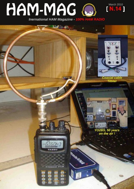
Coaxial cable<br />
Tester<br />
YO2BS, 50 years<br />
on the air !
YO2BS... 50 years<br />
On the air !<br />
[ HOMEBREW ]<br />
8040 meters wire antenna 15<br />
DX Calendar 24<br />
Continuous Feed source<br />
of 14VO68 4<br />
Coaxial cable Tester 6<br />
Quadrifilar Helix Antennas 31<br />
Make you own printed circuit 34<br />
[ CATEGORIES ]<br />
POST IT ! 3<br />
50MHz DX News 29<br />
Comic's <strong>HAM</strong> 39<br />
[ O.M. Discovering ]<br />
YO2BS, 50 years on the air 12<br />
The venerable VTVM 7<br />
10MHz / 1MHz calibrator 11<br />
MJF269 Review 17<br />
[ HISTORY ]<br />
The history of Torre Bert 36<br />
DX NEWS 22<br />
[ <strong>HAM</strong>MAG N.14 March 2010 ]
POST-IT !<br />
The breaking News<br />
Iceland Amateurs Receive New Privileges<br />
As of Friday, February 19, Iceland’s Post and Telecom Administration (PTA) granted temporary<br />
experimental access to the 4 and 600 meter bands at least through the end of 2010, according to<br />
Islenzkir Radioamatorar (IRA) President Jonas Bjarnason, TF2JB; the ITA is Iceland’s IARU Member<br />
Society. After obtaining a special license from the PTA, Bjarnason said that TF stations with “N” or “G”<br />
class licenses may now operate between 493510 kHz and 70.00070.200 MHz running 100 W.<br />
Amateur operations on both bands are granted on a secondary basis.<br />
Launch of New ARRL Web Site Delayed to "Get it Right"<br />
After meeting with ARRL staff on February 23 two days before the new ARRL Web site was to launch<br />
ARRL Chief Operating Officer Harold Kramer, WJ1B, made the decision to delay the unveiling of the<br />
Web site until late March. "Work on the new ARRL Web site has progressed at a frantic pace but there<br />
are still some potential 'bugs' that could affect members. We need to be sure we get it right," Kramer<br />
said. "Our members' security, information and ability to actually use of all the options on the new site<br />
outweigh any rush to meet an artificial deadline. It's just good customer service."<br />
The new Web site which will contain the online store, class registrations, audio, video, DXCC<br />
information, contest data, individualized member options and other 21st century opportunities for<br />
members is one of the largest technology upgrade activities that ARRL and Fathom, the company<br />
programming the site, have ever undertaken. "Reviewers have been unanimously impressed and are<br />
helping make sure we create the easiest, most enjoyable online experience possible," Kramer<br />
explained. According to ARRL Media and Public Relations Manager Allen Pitts, W1AGP, the current<br />
ARRL Web site is not only used by ARRL members, but is a prime reference source for engineers,<br />
hams and wireless technicians around the world, making it the premier place to find information about<br />
Amateur Radio, its activities and the sciences behind it. "The Web is our main face to the world, and the<br />
new Web site will be fantastic," he said. "Although we all regret the delay, I believe our members will<br />
appreciate our diligence about the ease of use, security and navigation for the new site."<br />
Tweets in space ISS gets web access<br />
In a high tech first, astronauts in space finally have Internet access.<br />
Space station resident Timothy Creamer has been working with flight controllers to establish internet<br />
access from his orbital post ever since he moved in last month. He posted the first live tweet truly from<br />
space. "Hello Twitterverse!" he wrote. Before, astronauts had to send Twitter updates by email to<br />
Mission Control in Houston. Then controllers posted the tweets. The International Space Station crew<br />
can now use an onboard laptop to see a desktop computer at Mission Control, and thereby browse the<br />
web. This remote internet access is possible whenever there is a solid highspeed communication.<br />
Win a... One year active member of Ham-Mag.<br />
Send us an article and when it is published you win your adhesion.<br />
Tell it to your friends.<br />
Send article to : f5sld@free.fr<br />
[ <strong>HAM</strong>MAG N.14 March 2010 ]
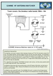
Continuous feed source of 14VO-68<br />
By YO6QCZ<br />
The confection ideea of this source came from the feeding necessity of some devices (like: clock ,<br />
economic light bulb at 12 V , radio stations) because of the lack of electric stream, on a definite limited<br />
time period (depends on the bettery capacity).<br />
I've chosen the usage of a slug (Pb) battery with 12V 7 Ah tight acid (used in a lot of industrial<br />
schemes, like : alarms, opening door latches, etc).<br />
I've thought for a scheme with the automatic charge possibility of the battery from the 220V network by<br />
the instrumentality of a redressortransformer and of a 555 tip circuit with the possibility of tuning the<br />
charging lintels (up) and (down) with the help of some semiadjustable.<br />
The charging I is given by the R4 resistance, which is arround the value of 0,2 A. The pieces are<br />
mounted on a lay with the exception of the transformer, of the fuse on the battery and of the LED diodes<br />
which signalls the state of device.<br />
Diode (LED1) signalls that the device is conectet to the 220V network.<br />
Diode (LED2) signalls the voltage presence to the vent + 13V<br />
Diode (LED3) signalls that the battery is charging ; This diode turns on and off automatically at an<br />
interval of approximate 30 seconds based on the voltage tunings the upper lintel and the lower lintel <br />
of the semiadjustables. The scheme is functioning from the start, but the two lintel semiadjustable<br />
must be adjusted.<br />
Stuffs list<br />
TR 1 220/15V 1 A<br />
P1 = B100C1500R<br />
Z1 DZ10V<br />
T1 BC171C<br />
T2 BD238<br />
C.I. NE555<br />
S1,S2 semiadjustable 0,5W 10K<br />
Sig 1 1A<br />
Sig 2 4A<br />
R1 330Ω 10,5 W<br />
R2 1K 10,5W<br />
R3 330Ω 10,5W<br />
R4 24Ω 2W<br />
R5 6K 0,5W<br />
R6 18K 0,5 W<br />
R7 – 220 Ω<br />
R8 – 1K Ω<br />
R9 – 2 K2<br />
Accum = 12V / 7 Ah<br />
S1 it adjusts for U max = 14,2 V<br />
S2 it adjusts for U min = 13,4 V<br />
Once made this two adjustments, the device is functional .<br />
I wish you : Success !<br />
Y06QCZ Dorin<br />
[ <strong>HAM</strong>MAG N.14 March 2010 ]
[ <strong>HAM</strong>MAG N.14 March 2010 ]
The Venerable VTVM<br />
by N4PRT, Patrick<br />
Alright Sherman, it’s time to join Mr. Peabody and “Set the Wayback Machine” for 1970. We have<br />
arrived in an average sized Midwestern town where we will visit two electronics operations—one a<br />
television repair shop and the other a ham radio shack. Observe closely, for we are looking for<br />
something very useful that can be brought forward to today’s shack workbench.<br />
Remember that these are still the days of the vacuum tube—solid state is becoming more common in<br />
home entertainment applications, but for the ham much of his or her radio equipment is still firmly based<br />
on “hollow state” devices. In both the TV shop and the shack, there is one piece of equipment that<br />
holds a position of prominence at the front of the bench—the vacuum tube volt meter, or VTVM.<br />
An RCA Senior VoltOhmyst holds court at the TV shop, while a Heathkit IM18 built by the amateur<br />
presides in the shack. While these two meters look quite different in shape, the surprise is that they<br />
have essentially the same circuit inside. In fact, the VTVM has changed little in its design since it was<br />
first introduced in 1916.<br />
Having identified our historic prize, we move forward to the<br />
present time and examine what a VTVM can do for us today. After<br />
all, are not our modern digital (DMM) and analog (VOM)<br />
multimeters much more accurate and versatile? As we will<br />
discover there are many things that one can accomplish with a<br />
VTVM that simply cannot be done reliably or with the same degree<br />
or responsiveness as with more modern equipment.<br />
The first task of course is to get one of these handy instruments<br />
into our possession. A quick way to find anything is to check<br />
eBay. A search of completed auctions reveals that a number of<br />
different brands and models can be had ranging from $1050 in<br />
price, with $25 the average cost. Other sources can be hams that<br />
are not using these anymore, estate sales, and hamfests. Make<br />
sure that the meter you are considering has its probes, powers on,<br />
and preferably has a manual.<br />
Quite a few brands are available. A short list of the most common include RCA, B&K, Knight, Heathkit,<br />
Eico, HP, Simpson, Triplett, and others. Test equipment manufacturers frequently offered several kinds<br />
of accessory probes to round out the capabilities of the VTVM—very similar to those found for<br />
oscilloscopes. These included high voltage, RF voltage, demodulator, and even specialty probes for<br />
temperature and pH. Due to the universal design of many VTVM’s, these probes will often work across<br />
brands and models.<br />
Older VTVM’s produced prior to the 1960s lack two important features.<br />
resistance—scales only reflect voltages and decibels.<br />
First, they do not measure<br />
[ <strong>HAM</strong>MAG N.14 March 2010 ]
Second, in the early 1960s a 1.5 volt scale was added to improve accuracy when measuring smaller<br />
voltages (even a .5 volt scale in some cases). A few models of older VTVM such as the Hewlett<br />
Packard 400 series actually had a vacuum tube in the probe itself. Another limitation is that the test<br />
leads were usually an integral part of the unit—hardwired to the circuitry and not interchangeable.<br />
While these meters can be made fully functional for today’s bench, it is recommended that a more<br />
recent and versatile vintage be selected.<br />
Now that we have a VTVM on the bench, the real question becomes what can we do with it that our<br />
DMM or analog VOM is not capable of? To answer this question let’s first look at how the VTVM works.<br />
In a nutshell, the VTVM uses a dual triode tube (usually a 12AU7) in a balanced bridge circuit to amplify<br />
incoming voltages. This sort of design provides several useful functions. A diagram detailing the most<br />
common VTVM circuitry is shown at the end of this article (RCA WV98A).<br />
The first is that a very high impedance (approximately 10 MΩ) is shown to the circuit under test. This<br />
provides a high degree of isolation between the metering circuit and the test circuit—resulting in a very<br />
low “load” placed into the tested circuit. Such a configuration is very convenient in low power, coupling,<br />
amplifier, and resonant circuits as it does not change the operational characteristics of the circuit. This<br />
characteristic is shared by many quality digital meters.<br />
The measurement of complex sine patterns or other forms such<br />
as square or sawtooth is best accomplished with the VTVM. In<br />
situations where there are likely to be rapid variances and<br />
transient spikes present in the signal, the VTVM shines with its<br />
rapid response and ability to correctly decipher the correct<br />
voltages at hand. This instrument is also relatively immune to<br />
false indications due to interference and strong electromagnetic<br />
fields. It is also much easier to determine the minimum and<br />
maximum changes in a circuit by following the meter needle<br />
than trying to make sense of a wandering digital display. This<br />
alone eases any receiver alignment process.<br />
A high degree of amplification in the metering circuit also means<br />
that very high resistances up to 1000 MΩ can be measured. This<br />
is useful in determining dielectric resistance, leakage of capacitors,<br />
transmission line characteristics, and isolation leakage. The<br />
amplification factor is also beneficial when measuring small audio<br />
or IF voltages, giving one a true indication of the performance of<br />
the circuit under test.<br />
A unique ability that a VTVM has that a DMM or VOM does not is<br />
to read AC voltages in both RMS (rootmeansquare) and PP<br />
(peaktopeak) values. The common DMM/VOM averages the AC<br />
sine wave and delivers an RMS approximation of the voltage. By<br />
using PP voltage measurement, more complex sine waves and<br />
other waveforms can be accurately measured—the added benefit<br />
being that the PP measurement coincides with how an<br />
oscilloscope measures voltage. Combining the VTVM with a<br />
scope delivers waveform observation that sh<strong>ares</strong> the same<br />
measurement standard.<br />
[ <strong>HAM</strong>MAG N.14 March 2010 ]
Here are a few of the better uses of your VTVM:<br />
• Measuring coupling and other capacitor leakage<br />
• Troubleshooting audio circuits<br />
• Measuring voltages in tuned and resonant circuits<br />
• Determining reactance and inductance of components<br />
• Alignment of tuned circuits<br />
• Measurement of potential 1500 V and above (with proper probe)<br />
• Direct measurement of high frequency voltages<br />
• Ability to measure DC in the presence of AC voltages<br />
[ <strong>HAM</strong>MAG N.14 March 2010 ]
As might be expected with any older test equipment, your “new” VTVM will likely need a little care<br />
before it can serve reliably on your bench. All paper based capacitors over time will become<br />
leaky—and require replacement. Depending upon the age of your unit is may be wise to simply replace<br />
the coupling and any electrolytic capacitors that may be present in the circuit.<br />
Rotary control switches and adjustable potentiometers become dirty through oxidation and<br />
contamination. These should be cleaned with a quality solution such as a spray on cleaner/lubricant or<br />
an application of a solution such as DeoxIT. This applies to calibration trimmers as well—a thorough<br />
cleaning and recalibration as given in the instruction manual is recommended.<br />
Interestingly, quite a few VTVM’s used a battery to supply the resistance measurement voltage. A first<br />
check of the interior of the meter will look at replacing this battery and repairing any damage done by<br />
leakage of an old cell. Some enterprising technicians have tapped into the tube filament voltage to feed<br />
a circuit that provides a stable 1.5 volt DC supply—thus eliminating the need for a battery.<br />
Once the dominant instrument in any electronics shop, the venerable VTVM still has a valuable place<br />
on the radio amateur’s bench.VTVM Sidebar Resources<br />
Although it has been many years since the majority of VTVM’s were made, a wealth of resource<br />
material is still available to the bench technician and hobbyist. A quick search of Amazon.com turned<br />
up nearly 20 unique used books detailing meter operation and a variety of troubleshooting techniques.<br />
The most complete reference for these meters is “The VTVM” by Rhys Samuel. Originally published in<br />
the mid1950s, copies in hard and soft cover are still available at a reasonable price. As noted, it is<br />
important to have a manual for your VTVM. If one did not come with your meter, a number of online<br />
resources exist that will provide you with one.<br />
Here is a list of a resources for the new VTVM user:<br />
Books<br />
101 Ways To Use Your VOM and VTVM<br />
Robert G. Middleton, 1959<br />
Troubleshooting With The VOM and VTVM<br />
Robert G. Middleton, 1962.<br />
Know Your VOMVTVM<br />
Joseph A. Risse, 1963.<br />
The VOMVTVM Handbook<br />
Joseph A. Risse, 1972.<br />
On The Web<br />
BAMA Manuals & Schematics<br />
http://bama.sbc.edu/index.htm<br />
73 from N4PRT<br />
[ <strong>HAM</strong>MAG N.14 March 2010 ]
10MHz/1MHz Calibrator/ Marker generator.<br />
By John R L Walker ZL3IB<br />
A simple frequency standard can be a useful accessory in the ham shack.<br />
Similarly the ability to include some sort of frequency marker into a spectrum<br />
analyser displayed is very helpful and this can be done using an external<br />
signal source. However an internal marker is handy so I constructed a very simple 10MHz/1MHz<br />
marker generator. This used a 10 MHz crystal salvaged from an old computer and in my unit produces<br />
a 'comb' of peaks on my spectrum analyser to over 350 MHz.<br />
Fig below. Marker generator<br />
(This article was first published in BreakIn July/Aug 2002)<br />
73 ! ZL3IB<br />
[ <strong>HAM</strong>MAG N.14 March 2010 ]
YO2BS - 50 YEARS ON THE AIR<br />
op. Aurel Sahleanu QTH : Timisoara ROMANIA<br />
I Was born 73 years ago in the city of Timisoara, almost a half million<br />
inhabitants, which is the second large city in Romania after Buch<strong>ares</strong>t,the<br />
capital city.<br />
In the ancient times this territory was populated by Trac tribes (from the Greek<br />
branch), which where defeat by the Romans in the year 101106 a.C. and so<br />
they become a part of the Roman Empire during almost 200 years in the<br />
beginning of the new era after Christ.<br />
So, the Romanian language is very similar to the other Latin roots languages and for us is very easy to<br />
understand Italien, Spanish, French and Portuguese.<br />
The history of our town begins 750 years before,when there has been built a military stonghold,which<br />
ruins can be seen till to day in the middle of the city. The first written document found from this period<br />
was from mid of the 13th century.<br />
In the 1617 century the ancient city was under the Turkeys government and than in the 1819 century<br />
under the dual AustrianHungary Empire. In the beginnig of the 20th century, after the first World War,<br />
the region of Transylvania (in the center of the country) and the Banat county, (in the extremely western<br />
corner of Romania) which capital city is Timisoara become a part of Romania, been populated in<br />
majority by romanians.<br />
At the present time Timisoara is a big university and industrial city, with a Sciences University,a famous<br />
Technical University and a well known Medical University, with all about 150 000 students. There are<br />
also many factorys,in special electrical,chemstry and construction companies. We have many parks,<br />
hotels, restaurants, an operahouse,<br />
a philarmonya,three theaters,a nice football and athletics stadium, a big orthodox cathedral,and much<br />
more others.<br />
Now about me :<br />
My profession is eletroengineer,reired now for 10 years. I was<br />
working 40 years in the field of electronics,among them 25 years as<br />
chief of the Technical Department of the Romanian Radio and<br />
Television Broadcasting Corporation,Directorate for the West of the<br />
country with the base in Timisoara. I am married with a charmy lady<br />
which is my wife and we have two sons,both of them electroengineers,but<br />
no one like to become a <strong>HAM</strong>. The olderst,emigrate in<br />
Canada works for an electronic company in Toronto,and the<br />
youngest which emigrate in Germany works by the Siemens<br />
Company in Ludwigshafen.<br />
Do have a pretty niece from my oldest son and a lovely nephew from<br />
the youngest son. May be they would like to become <strong>HAM</strong>s,who<br />
knows…<br />
My only hobby is amateur radio,and especially DXhunting on the<br />
VHF bands. Don’t like contests and UHF work…HI<br />
[ <strong>HAM</strong>MAG N.14 March 2010 ]
I discovered the world of radio when I was a 15<br />
years old schoolboy. It was a very interesting event<br />
which marked my entire life and also my career :<br />
A day,I think it was in the autumn of 1952,I took the<br />
old tuberadio receiver of my family to a repair shop.<br />
The radio was out of order next I opened it to see<br />
what is inside. After that operation the radio makes<br />
a big noise when tuning,and noting else to hear…<br />
The old man in the shop took a shavingblade and<br />
fix the problem imediately,reseting the distance<br />
between the plates of the variable capacitor. When I<br />
asked him how much cost the repair,the old man says : “ Nothing “. Than looked at me asked if I would<br />
like to help him repairng radios,and he will learn me all about radiorepair. I was astonished and replied<br />
him that I am a schoolboy and I must go at school everyday. He says : “Nevermind,you shall come after<br />
school,in the afternoon” . After a short thinking I agree,and so I get an apprentice in radiorepair,during<br />
the next two years.<br />
I heared from amateur radio as I graduated from the highschool and get a student in the first study year<br />
of the Technical University of Timisoara,in the autumn of 1954 year.<br />
Once I saw in downtown a panel with beautiful color QSLcards from all over the world, which impressed<br />
me very much (and that’s the reason I love collecting QSLcards till to day ), and an invitation for youth<br />
to participate to an exhibition of the radioamateurs.<br />
There where some exponates of rdioequipments built by the radioamateurs,and also a radiostation<br />
which makes some demonstrative QSOs. I was very excited and I decided to become a <strong>HAM</strong>. So I<br />
registered my self to the courses for beginners,by the County Radioclub and get instructed in Morse<br />
code,radiotraffic,get some notions of radiotechniq Qcode and English language. So,in 1955 I become<br />
a SWL with the call sign YO2215. I was a very enthusiast SWL during the next two years,collected<br />
QSLcards from more than 100 cuntries,and got some SWL awards like DXCC,HAC,HAE and others.<br />
In 1957 I become an operator by the County Radioclub station YO2KAB and in 1959 after passing the<br />
third class examination I got my personal call sign YO2BS as a novice operator,and begun working CW<br />
on 3,5 and 7 MHz,with a homebrew receiver and 25 W transmitter. In 1961 after a hard examination in<br />
Buch<strong>ares</strong>t I got the first class license (for all HF bands,400 W imput ).In those times in Romania where<br />
nothing to buy from radio transmitters or shortwave receivers. Having the skill and the necessary<br />
knowledges I started to built my self the radioequipment I<br />
needed for the hobby. So I built some tubes radioreceivers<br />
and transmitters and started working in CW and AMPhone<br />
with 300 W. After apparition of SSBmode,in 1968 I built an 100<br />
W SSB transmitter and than in 1970 a SSB 5 band 100 W<br />
transceiver , a 400 W liniar amplifier,and a 2 element cubical<br />
quad antenna,and started working very intensive in SSB,been<br />
between the first 5 SSBusers in our town. Being more and<br />
more busy with my professional activity,and don’t found any<br />
more the necessary time for my hobby radioconstruction,I had<br />
the oportunity and bought myself in 1975 an HW 101 from<br />
Heathkit (a 100 W SSB tansceiver in kit), which I assembled<br />
my self in my free time. With this nice equipment I begun<br />
effectively the DX hunting. The outstanding propagation in<br />
those years,helps me to make beautiful DXQSOs reaching<br />
over 300 countries in CW and SSB and getting also over 50<br />
<strong>HAM</strong>awards.<br />
[ <strong>HAM</strong>MAG N.14 March 2010 ]
In 1995 I bought a FT 890 AT transceiver from Yaesu and<br />
started working in digimodes and in 2000 a Kenwood TS<br />
850 SAT ,a beautiful radio,which I use also in presnt time.<br />
I kept also my old equipments and use the HW 101 for<br />
SSTV and RTTY mode,the FT890 AT for PSK and<br />
OLIVIA mode and the TS 850 SAT with the Liniar<br />
Amplifier 400W for CW and SSB mode. Antennas I used :<br />
the 2 element 3 bander CubicalQuad is now damaged<br />
after a big storm,have a 201510 m GP antenna for the<br />
classic bands and another 301712 m GP for the WARC<br />
bands on the top of the towerbuiding I live<br />
For the lower frequencies I have a Windom antenna<br />
which I use for the 40 and 80 m bands and a shorted dipole (with end coils ) for 160 m which are<br />
installed between my<br />
location and another high building.<br />
At the present time I do have confirmed 327 countries ( mixed ) on the HF bands and look for to carry<br />
out the 9 band DXCC (need only 15 more countries on 160 m band ).<br />
In our town we had about 20 big DXmen from my generation. Between them I mention the : YO2BA<br />
(SK), YO2BB , YO2BC (SK) , YO2BD ( now DL9FCD ), YO2BI (SK), YO2BL ( now DL4VAQ ) , YO2BM ,<br />
YO2BN (SK), YO2BO ( now WB2AQC ) ,YO2BP , YO2BQ (SK), YO2BS (my self), YO2BU (SK) and<br />
YO2BW (SK) .<br />
Today there are more than 30 another young <strong>HAM</strong>s (with<br />
3 letters at the suffix) which operate especially in digimodes<br />
and also phone on UHF. Unfortunately the new<br />
generation of radio amateurs don’t know the Morse code<br />
(which is not needed any more to get a <strong>HAM</strong><br />
license),and they could not be able to work in CW which<br />
is a big handicap getting a great DXman,most of the<br />
rare DXs (DXpeditions in exotic Islands on antipodes)<br />
works only in CW. That’s the reason I think the era of the<br />
great DXers is setting down now. A new communications<br />
era rise’s and may be one day the most common DX<br />
QSO will be on DigitalTV trough satellites. Will see…<br />
Your friendly Aurel Sahleanu YO2BS.<br />
[ <strong>HAM</strong>MAG N.14 March 2010 ]
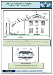
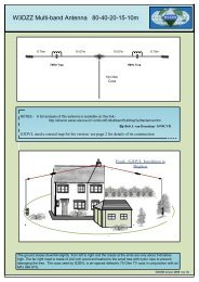
80 40 Wire antenna<br />
By Chris Wright VK2UW<br />
I designed this antenna to suit a small yard where Hams are restricted to either only vertical antennas<br />
or trapped antennas.<br />
This way you can use a full 1/2 wave Dipole on both 80 / 40 mts and by doing the same if needed for<br />
other bands including 160 / 80 mts etc even down to 15 / 10 mts, you can also lengthen the fibreglass<br />
rod so as to make a Fan Dipole to include other bands if needed.<br />
If your yard is smaller again you can lengthen the fibreglass rod so as to shorten the over all length<br />
even more.<br />
Feeding the antenna is entirely up to the operator as you can feed it direct or with a 1 to 1 balun. Make<br />
the centre point a minimum of 6 mts and drop the ends down to at least 3.5 mts from the ground.<br />
The antenna is easy to tune as all you have to do is let the end guy ropes loose and alter the length of<br />
the wire element on each side of the insulator, set the 80 mt one up first : if SWR is lower higher up in<br />
the band then just lengthen the wire dipole and the same goes for 40 mts as well.<br />
The heavier the wire preferably a multi strand wire like earth cable is suitable and will give a better band<br />
width and low SWR over that range.<br />
I do not use an ATU on this antenna even using my QRO Emtron Amplifier both on 80 and 40 mts.<br />
Power rating depends on how you feed the antenna and the rating of the balun and guage of wire, I<br />
usually wind my own baluns by either using Triifular type baluns or a Heavy duty Toroid type with Triifular<br />
windings. If using a PVC pipe and Triifular windings it depends on the size of the PVC that you<br />
use to wind the windings on as to the power handling and also the wire size come into it as well.<br />
I purchased the fibreglass rod that is used on electric fences and instead of using eye bolts as shown I<br />
used PVC pipe and cut it 75mm or 3 inches long and drilled holes 1/2 inch or 12.5mm in from each end<br />
and slid these down the fibreglass rods 1 inch or 25mm from each end and drilled a 1/8 hole through<br />
the fibreglass just above the PVC pipe and tied a wire through this and down under the PVC pipe and<br />
wrapped it round the fibreglass rod so as to stop the insulators sliding together and maintaining the<br />
spread at the fibreglass rods.<br />
I also used the same PVC pipe and hole setup for the Insulator where the 80 / 40 mt dipoles are<br />
terminated on the lower side of the antenna. These measurements will change due to location / ground<br />
factor and how you mount the antenna. The measurements are a guide as this is what the one that I<br />
use is set at.<br />
You can use this setup as an inverted "V" or straight dipole steup or even in a "L" shape in the back<br />
corner of your yard if needed. You can make up many different types this way for different bands<br />
especially for DXpeditions and the like or for travelling.<br />
I also found by just changing the length of the original antenna you can tune in many other bands, so by<br />
marking the ends on one or the other of the 80 / 40 dipoles you can have it setup where you want to<br />
use it most, and also eliminate the use of an ATU in line.<br />
(Pictures on the next page)<br />
73's de Chris Wright VK2UW<br />
[ <strong>HAM</strong>MAG N.14 March 2010 ]
[ <strong>HAM</strong>MAG N.14 March 2010 ]
MFJ269 Review<br />
By VK2ZAY, Alan<br />
After my review of my MFJ207 Peter VK2TPM offered me his MFJ269 to<br />
play with for comparison. Naturally I jumped at the chance. The MFJ269 is<br />
the fullyfeatured descendent of the earlier and simpler antenna bridges<br />
like the MFJ207. The manual can be found on MFJ's website.<br />
The device is microprocessor based with an LCD interface and two main control buttons "Gate" and<br />
"Mode". There is also a Frequency band switch, a reduction geared tuning capacitor, power and UHF<br />
mode switches. Two analogue meters display SWR and impedance magnitude continuously, offering a<br />
trending display which is more userfriendly than the figures on the LCD display. In UHF mode there is<br />
a "bargraph" of sorts on the 2nd line of the LCD for trending SWR.<br />
The unit tunes about 1.76 MHz to 172.7 MHz in six<br />
overlapping bands. There is also a "UHF" switch that triples<br />
the oscillator in the 114170 band giving 415470 MHz<br />
coverage the edges of which are enforced in software, the<br />
display telling you to increase or decrease frequency until<br />
within that band. UHF supports only loss and SWR features,<br />
not reactive measurements likely because bridge<br />
performance issues at UHF would have required extensive<br />
calibrations to have any hope of accuracy.<br />
The coaxial connector is a Ntype and is surrounded by a generous rubber gasket. The frequency<br />
counter input is a BNC. The DC plug is a conventional unit, tip positive, I am unsure what internal overvoltage<br />
and polarity protection it has. There is a large grounding lug also provided.<br />
Features<br />
There are 4 "Main" analysis features and 3 additional menus of Advanced ones. The advanced ones<br />
are mostly just different presentations of the same data from the bridge voltages (impedance in polar<br />
form, reflection coefficient, return loss, etc), but there is the option to select a different "Zo" for the<br />
calculations and also a twofrequency point semiautomatic calculating feature for line length, distance<br />
to fault, etc. The line length and fault distance calculations are pretty good, resolving several short (~2<br />
metre) lines and offering compensation for velocity factor.<br />
By pressing the "Mode" button you can cycle through the different modes, both main and advanced<br />
(once entered). Holding both the "Mode" and "Gate" buttons gives access to the advanced menus. The<br />
"Gate" button is used in frequency counting mode and as an enterkey of sorts in the calculating<br />
modes. Holding both buttons down on startup then alternatively pressing them as it boots enters the<br />
"Test" mode which gives a display of the raw ADC data for calibration of the unit with a set of calibrated<br />
dummy loads. The button mashing required to enter "Test" takes some practice, thankfully it isn't<br />
something you'd be doing often. The software version is displayed at boot, in this case 4.46, copyright<br />
2004.<br />
[ <strong>HAM</strong>MAG N.14 March 2010 ]
Impedance Analysis<br />
The default "main" mode is the "Impedance R + X" mode and displays<br />
frequency, VSWR, and impedance as Resistive and Reactive magnitude<br />
(Rs +/ jXs) which update continuously as you tune around. The sign of<br />
the reactance is not resolved and displayed, which is pretty typical of the<br />
bridge system the device uses. The frequency counting is probably the<br />
"killer feature" of the device as well as the reactive magnitude display<br />
which allows searching for true resonances not just minimum reflection<br />
coefficient magnitude.<br />
The impedance mode does seem to work pretty well, especially below<br />
50 MHz, but is limited by the device's calibration accuracy. I am not very<br />
confident the unit I was playing with is calibrated properly, resistive<br />
magnitudes reads high, sometimes more than double and above 300<br />
Ohms resistive the reactive magnitude rises very quickly too, even with<br />
a "pure" resistance in the lowest frequency band. This and other<br />
behaviour I noticed suggests the "Vz" channel gain is a bit high. Upon checking the calibration pots<br />
under the battery holder I noticed that R72 was bottomed out, offering insufficient range to properly<br />
calibrate the unit as described in the calibration procedure. This is suggestive of mismatched or<br />
damaged diodes in the bridge or perhaps an incorrect resistor value or tolerance catastrophe. As the<br />
unit is not mine I didn't pull it apart to inspect the rest of the circuit and attempt to diagnose it further.<br />
Coax Loss<br />
The second "main" mode is "Coax Loss". It appears to simply display half the return loss measured by<br />
the bridge. When an unterminated coax line is attached the bridge<br />
sees the throughandback (returned) loss of the line, which is twice<br />
the line loss for that particular length. Similarly you can attach<br />
attenuators and other lossy devices to the unit and measure their loss<br />
this way. The loss maximum appears to be 24 dB and is likely limited<br />
by the best bridge directivity over its frequency range (ie 48 dB, pretty<br />
good). As the unit is measuring with a 12 bit ADC a linear signal (not a<br />
log detected one) the dynamic range is pretty limited and the loss<br />
quantisation is fairly coarse. For "good" vrs "completely waterlogged"<br />
measurements of coax it is likely sufficient.<br />
One annoying thing is the lack of autozeroing, this particular unit<br />
would always read about 0.9 1.6 dB return loss at HF. It would be<br />
nice to have software zeroing. In fact I can't see why the entire device<br />
could not have been designed to ship with a set of calibration loads and full software fine calibration. I<br />
do understand that some of the gain settings are quite critical, especially for reactance zeroing with the<br />
limited dynamic range offered by the 12 bit DACs fed by linear detectors. Still it would be nice to have<br />
"tare"style zeroing for some measurements.<br />
Capacitance and Inductance Measurement<br />
The Capacitance and Inductance measurements simply compute the reactor value that matches the<br />
current reactive magnitude reading at the current frequency. It has no way of telling if the load is<br />
actually inductive or capacitive, and once outside the few ohms to 1.5 kohm range of reactance<br />
magnitude the software stops giving you a solution. This makes perfect sense, you just need to tune the<br />
VFO until the frequency offers a reactive magnitude inrange of the unit. The computed values are most<br />
accurate when the reactance magnitude is close to the bridge reference resistance (50 Ohms). This<br />
particular unit read high, about 19 pF high (about 6 pF of which was the test fixture) on average and<br />
again there is no way to null it.<br />
[ <strong>HAM</strong>MAG N.14 March 2010 ]
Inductance was probably worse but I didn't test it extensively, only a<br />
few trial inductances were compared to values measured by my LC<br />
tester. The LC measurement is nice to have, but I wouldn't trust it in<br />
fact I'd go as far as to suggest using the frequency counter feature<br />
along with an external jig like the LC tester instead.<br />
Correctly calibrated the general measurement method is probably fine<br />
and quite useful as it tells you the true impedance of the reactive<br />
component at radio frequencies (unfortunately only those that present<br />
a 71500 Ohm impedance). For testing a component for spurious<br />
resonances this is very useful, but in practice I couldn't seem to easily<br />
find misbehaviour in capacitors. Inductors on the other hand were fairly<br />
easily tested for self resonance, but being placed in the tester<br />
environment pulled their selfresonances quite a lot. Dipping them<br />
instead is probably more reliable.<br />
Frequency Counting<br />
The frequency counting feature works as advertised. It can accept<br />
signals up to 5 volts and has an highimpedance input. I could easily<br />
get a stable measurement with just a few turn coil plugged into the<br />
input using my dip meter as a signal source from several inches. The<br />
counter counts to beyond 170 MHz, I didn't test it higher. I assume the<br />
"UHF" feature actually counts the VHF generator and triples the value<br />
in software? I can't see a counting range spec in the manual. The<br />
gating works as expected, long gating times give more resolution<br />
figures. The reference seems stable and accurate enough for the<br />
resolution offered.<br />
Advanced Features<br />
Of the "Advanced" modes the stub length and resonance searching ones are probably the most useful.<br />
The stub length helpers are great for cutting matching and phasing stubs. Accuracy for 1/4 lines seems<br />
pretty good when compared to dipping a line with other instruments. It is unfortunate that the physical<br />
lengths are only given in feet. A metric physical measures software option would be nice, but<br />
considering this is a US product this is perhaps not surprising. The resonance searching mode makes<br />
the Impedance magnitude meter show Reactive magnitude while looking for a null. Oddly it does not<br />
use the LCD bargraph like SWR in UHF mode, instead showing Xs numerically.<br />
The match efficiency mode is arguably the most useless feature. I'm not really sure what the point of it<br />
is. I guess there was extra room left in the MCU code space, so yet another "feature" was invented to<br />
fill it. Personally I'd prefer metric measures or software nulling instead.<br />
Use as a Dipper<br />
I understand there is an optional dipper coil set for the MFJ269? I just<br />
plugged my few turns of wire on a BNC into it and tried it out on some<br />
inductor selfresonances. It works quite well on HF and VHF. I'm not too<br />
confident about it on UHF, but the UHF range is quite narrow which makes it<br />
fairly useless for dipping anyway.<br />
[ <strong>HAM</strong>MAG N.14 March 2010 ]
Power Consumption<br />
The device does guzzle power. On HFVHF in the default<br />
mode it pulls 140170 mA (rising with frequency). On UHF it<br />
pulls over 350 mA! In counteronly mode it still pulls 90 mA.<br />
The AA batteries won't last long, and it takes 10 of them. Unlike<br />
the MFJ207 at least you only need to remove two short<br />
machinethreaded screws to access the batteries.<br />
The external power option is almost mandatory (use at least a<br />
500 mA plugpack), but it does offer the ability to charge<br />
rechargeable batteries inside the unit by changing a jumper on<br />
the PCB. I have no idea how well it manages them if you<br />
choose this option.<br />
By default the unit enters a sleep mode to reduce power consumption after a period of inactivity. This<br />
would help extend battery life, but it still pulls more than 50 mA. The sleeping feature can also be<br />
disabled by holding down buttons while the unit is powered on and remains disabled until the power is<br />
cycled again, much like Test mode.<br />
Comparisons to the MFJ207<br />
The 207 is very basic compared to the 269. The 269's<br />
frequency counting and reactive magnitude display are its<br />
best features. The 269 has none of the FMed oscillator<br />
problems of my particular 207 and has much improved<br />
buffering and harmonic distortion. There is a pot in the 269<br />
for setting buffer bias up to minimise the harmonic energy.<br />
I didn't test it extensively, but there is a detailed procedure<br />
available using a coax stub instead of a spectrum analyser<br />
to ensure this is set correctly.<br />
Tests with narrow band antennas like my balcony HF<br />
vertical and bicycle loop antenna show it is very much<br />
improved over the 207. I can resolve the resonance of my balcony vertical on 80 metres with the 269<br />
fairly easily where it is next to impossible with the 207.<br />
I even tried measuring a colourburst crystal with the 269. The xtal resonance is very steep and the<br />
analyser tries its best, but it is simply not sufficiently stable or well buffered enough to stay in the<br />
resonance. You can detect it and even get a fairly good idea of its frequency however, and see spurious<br />
resonances of the xtal as well.<br />
The 269 covers part of VHF where the 207 stops just above 30 MHz and the 269 also has the narrow<br />
UHF option. On UHF the 269 is essentially as limited as the 207 is on HF, measuring just return loss. I<br />
am highly suspicious of the UHF feature's accuracy and debate it actual usefulness for most <strong>HAM</strong>s.<br />
Like the 207 the 269's SWR meter is largely just for trending.<br />
The calibration point is 2:1 (using a 100 Ohm load), above and below this the displayed figure is quite<br />
wrong. The LCD display however shows the correct figure, at least below about 5 and of course if the<br />
unit is calibrated properly. (The impedance meter is a bit better, its calibration point is 50 Ohms using a<br />
flat load. Again the screen gives a more accurate reading.)<br />
[ <strong>HAM</strong>MAG N.14 March 2010 ]
DX NEWS<br />
From the Web (opdx)<br />
5K, COLOMBIA<br />
A DXpedition is being planned to operate from the Laguna Grande de la Sierra, from where you get the<br />
legendary rock formation called Devil's Pulpit, the peak Sugarloaf Peak and Concave. Callsign will be<br />
5K7SNC. This will be only a two day operation. Announced dates and hours of operation frequency are:<br />
April 1st 7140 kHz between 17002400z<br />
April 2nd 7140 kHz between 00001700z<br />
QSL via HK3OCH. For more details and possible updates, visit QRZ.com under 5K7SNC.<br />
5R, MADAGASCAR (IOTA Op)<br />
Michele, IK5ZUI, will be active as 5R8UI from Nosy Be (AF057) starting early March. He will stay there<br />
possibly for one year. More details are forthcoming.<br />
7P, LESOTHO<br />
Pista, HA5AO, will once again be active as 7P8AO from the Trading Post Lodge, Roma near Maseru,<br />
between March 822nd. Activity will be on the HF bands, 8010 meters using CW, SSB and RTTY. He<br />
will be using an ICOM 7000 transceiver w/300 watt amp into a 10.2m wire vertical antenna with a SG<br />
235 automatic antenna coupler. QSL via LoTW, or via HA5AO by the Bureau or direct. An online log<br />
search will be available on Pista’s Web site at:<br />
http://ha5ao.novolab.hu<br />
8Q, MALDIVES<br />
Alex, UX4UL, will be active as 8Q7IA from the Maldives (AS013) between now and May 18th. Activity<br />
will be mostly CW and PSK. Currently Alex has antennas installed for 40/20/17 meters. QSL via UY5ZZ.<br />
CO6, CUBA<br />
Operators Luis/CO6LP, Orelvis/CO6LC, Yordany/CM6YAC, Carlos/ CO6CAC, Jose/CO6EC and<br />
CO6YWR will be active as T46A during the ARRL DX SSB Contest (March 67th) as a MultiSingle<br />
entry. QSL via CO6LC.<br />
LZ123, BULGARIA (Special Event)<br />
Members of the Balkan Contest Club (LZ1KZA) will operate with special event callsign LZ132GO<br />
between March 131st. Activity is to commemorate 132nd anniversary of the liberation of Bulgaria from<br />
Ottoman yoke by Russia. QSL via LZ1ZF. Special event station LZ132GO also counts for 10 points<br />
towards "St. Teodosii Tyrnovski Award":<br />
http://www.balkanclub.org/awards.htm<br />
ON30, BELGIUM (Special Event/Contest)<br />
Egbert, ON4CAS, Secretary of the Belgian IARU Society UBA & Award Manager, informs that special<br />
event station ON30ON (Oscar November Thirty Oscar November) will be active during the months of<br />
March, April, September and October of 2010. Activity is to commemorate the 30th edition of the<br />
Belgian "ON Contest". The contest was first organized in 1980 to celebrate the 150th anniversary of the<br />
Kingdom of Belgium. Since then, the yearly event lasting just four hours on a local Sunday morning <br />
has become increasingly popular. QSLs for ON30ON go via the UBA bureau or direct to ON4CAS. A<br />
special certificate which can be achieved for free has been created in PDF format. Full details are<br />
available at:<br />
http://users.telenet.be/egbert.hertsen/on30on.html<br />
[ <strong>HAM</strong>MAG N.14 March 2010 ]
PACIFIC TOUR<br />
Hugh, K6HFA, has announced that he will be in the South Pacific from early March until late April and<br />
plans to activate the following islands: Samoa (5W) March 310th; IOTA OC097 Tonga (A3) March<br />
12thApril 2nd; IOTAs include OC049, OC064 and OC123 Wallis (FW) April 612th; IOTA OC054 <br />
Tuvalu (T2) April 1321st; IOTA OC015 Fiji (3D2) April 2326th; IOTA OC016 or OC156.<br />
Hugh plans to be on CW, SSB and possibly RTTY using 100 watts into a multiband vertical antenna<br />
(for 8015m). Look for him on the IOTA frequencies or possibly other frequencies. Hugh plans to call by<br />
areas (EU, NA, SA, ASIA... etc..) per propagation. Callsigns are TBA. QSL via K6HFA. Look for more<br />
details to be forthcoming.<br />
TI8, COSTA RICA<br />
Operators Keith/W4KTR, Eddie/K4UN, Bob/W4BW, Lex/W4XO, Carlos/TI2KAC, Juan Carlos/TI2JCY<br />
and TI2ZM will be active as TI8M from Costa de Pajaros, during the ARRL DX SSB Contest (March 6<br />
7th) as a Multi? entry. QSL via TI2KAC, direct preferred but bureau "OK".<br />
V2, ANTIGUA & BARBUDA<br />
Alan, N3AD, will be active as V26M between March 47th. Activity will include the ARRL DX SSB<br />
Contest (March 67th) as a SingleOp/HighPower entry. Alan informs OPDX that he will definitely be on<br />
Thursday afternoon and evening and on Friday before contest. His activity will be on the HF bands only<br />
160/80/40m in evening and 20/15/10m during daytime. QSL via his home callsign.<br />
YI9, IRAQ<br />
Operators Dooley/W4VDW and Louis/KI4VEU are now active from Baghdad as YI9VDW and YI9VEU,<br />
respectively. Operations are anticipated to begin in late February or early March. Activity will be on 160<br />
10 meters including the 30/17/12m bands. Plans are to also activate an EchoLink node. QSL YI9VDW<br />
to his home callsign W4VDW and YI9VEU via LoTW. Echolink is YI9VDWR (node # 496161), on daily<br />
between 12001230z (or when you see it active!). HF activity will take place for YI9VDW between<br />
March 17th. Suggested frequencies are: 20m: 1412514300 kHz SSB between 15001600z; 40m:<br />
71007200 kHz SSB between 16001700z.<br />
2M, SCOTLAND (Satellite Op)<br />
Paul, 2E1EUB, will once again be active as 2M1EUB from March 20th for 7 days. He will be active on<br />
all the satellites from northeast Scotland in the Cairngorms National Park. Also, look for him on 160 and<br />
80 meters. Checkout (QRZ.com) under 2M1EUB for more info.<br />
The Council of Europe Radio Amateur Club will be activ March 12th to 14th with the call<br />
TP60CE in SSB, CW, RTTY, PSK, SATELLITE to commemorate the 60th Anniversary of the<br />
Convention of Human Rights.<br />
QSL via F5LGF<br />
Web site: http://ewwa.free.fr<br />
[ <strong>HAM</strong>MAG N.14 March 2010 ]
SM3CVM Presents :<br />
THE DXCALENDAR<br />
ANTARCTICA TOUR; VP8/A, VP8/G, VP8/H, VP8/O by W2APF, traveling aboard the ship National<br />
Geographic Explorer. He is visiting the Antarctic region until Mar 5. He will sign W2APF/C6A/mm from<br />
onboard the ship and W2APF/KC4 from the Antarctic mainland. He plans shore excursions on the<br />
Falklands, South Orkneys, South Shetlands and South Georgia Islands and will use the call VP8DML<br />
from there. An exact timetable is not known in advance. Learn more at:<br />
http://www.expeditions.com/Ship_Detail92.asp?Ship=20<br />
QSL cards for all callsigns should be sent via W2APF<br />
PRINCE EDWARD & MARION IS; ZS8M AF021. ZS1HF has announced he will be active from Marion<br />
Island "from the end of April once the 'SA Agulhas' has returned to Cape Town". He says he is taking up<br />
"the position of radio/electronics technician for a year". ZS8M is expected to be QRV in late Aprilearly<br />
May. Pierre will be active in his spare time, and will operate SSB, possibly with some RTTY. QSL direct<br />
to ZS1X.<br />
1/3 PITCAIRN I.; VP6AL<br />
QSL OK via eQSL or direct: c/o P.D.C Hahei, RD1, Whitianga, New Zealand.<br />
1/3 NEW ZEALAND; ZL/G6PAA<br />
He will probably visit both the North Island (OC036, WLOTA LH0069) and South Island (OC134,<br />
WLOTA LH0342). Activity will be 8010 meters using CW, SSB, RTTY and PSK. He will use 100 watts<br />
into a dipole. QSL via his home callsign, direct or by the Bureau.<br />
2/3 BELIZE; V31RI<br />
by DL6RAI. QSL via home call, direct or bureau.<br />
2/3 11/3 ST. LUCIA; J68JA NA108<br />
by W5JON. Activity will be on 1606 meters (including 60m) on SSB. He will use an ICOM IC7000, KL<br />
400 Amp (350 watts) into the following antennas: ZS6BKW design multiband dipole, and a 3 element<br />
yagi on 6m. Activity will also include the ARRL International DX Phone Contest (March 67th) as a<br />
SingleOp/AllBand entry. QSL via W5JON.<br />
3/3 10/3 COCOS (KEELING) IS; VK9 OC003<br />
by NL8F. Activity will be on 8010 meters, plus 6 meters, and an entry in the ARRL International DX<br />
Phone Contest (March 67th). He will be using a vertical antenna. He does not know what his callsign<br />
will be, but he is hoping for VK9COF (or possibly VK9C/NL8A). QSL via K8NA.<br />
3/3 2/4 RODRIGUES I; 3B9WR AF017<br />
from Cotton Bay, Rodrigues Island by G3LZQ. Activity will be on all bands 16010 meters, probably and<br />
mainly CW, but with a focus on the lower band (QRN permitting). Look for him to be in the RSGB's 73rd<br />
Commonwealth Contest (March 1314th). QSL via his home callsign.<br />
[ <strong>HAM</strong>MAG N.14 March 2010 ]
3/3 AFGHANISTAN; T6LC<br />
from Gardez in Takia Province By W4JJ. Mainly 40 and 20 meter CW/SSB. Check 14301800z. QSL via<br />
K4MJN.<br />
3/3 GRENADA; J37BO<br />
by K4LTA, including a MultiSingle entry in the ARRL DX CW Contest as J38A along with NK4N. QSLs<br />
via K4LTA.<br />
4/3 9/3 NICARAGUA;<br />
YN2EA, YN2UO, YN2MG and YN2TKI by WF5W (YN2EA), K5UO (YN2UO), NM5G (YN2MG) and<br />
WB5TKI (YN2TKI). They plan to operate CW, SSB and RTTY on 16010 metres, and to participate in<br />
the ARRL DX SSB Contest as YN2EA (MultiSingle). During noncontest periods, they will have two<br />
stations active on all modes and bands. QSL for all callsigns via W5PF and LoTW. For information, look<br />
at http://www.tdxs.net/yn2ea.html<br />
5/3 12/3 SAINT MARTIN; FS/KT8X<br />
This will be a holiday style operation with an emphasis on the 30/17/12 meter bands using CW, SSB<br />
and RTTY. However, he does plan to enter the ARRL DX SSB Contest as a SingleOp entry. QSL route<br />
will be the "Logbook of The World" (LoTW).<br />
5/3 16/3 ST. LUCIA; J6/G3PJT NA108<br />
Main activity will be concentrated during the RSGB Commonwealth Contest, outside the contest he will<br />
operate holiday style mostly on 80 and 30 metres CW.<br />
5/3 24/3 THE GAMBIA;<br />
C56KR by OZ8KR. Activity will be holiday style with operations on 8010 meters SSB, using 100 watts<br />
into wire antennas close to the Atlantic Ocean. QSL via OZ8KR.<br />
5/3 ANTARCTICA TOUR;<br />
VP8, VP8/G, VP8/H, VP8/O and KC4 W2APF will be traveling on board the ship "National Geographic<br />
Explorer" heading to the Antarctica region. He is expected to be operating under the following callsigns<br />
(specific dates were not provided): W2APF/C6A/MM While on board the ship "National Geographic<br />
Explorer"; http://www.expeditions.com/Ship_Detail92.asp?Ship=20/<br />
W2APF/KC4 While in Antarctic territories VP8DML While in the territory of the Falkland Islands (VP8)<br />
including South Shetlands Islands (VP8/H), South Orkney's Islands (VP8/O) and South Georgia<br />
Islands. QSL all activity via W2APF.<br />
8/3 THAILAND; HSØZJF AS101<br />
by ON4AFU. During his stay he plans to activate the Malay Peninsula East Group (AS101) during this<br />
timeframe as HS0ZJF/8. He will also make a trip to Cambodia between February 215th, 2010, and be<br />
active as XU7AFU. All his activities will be on all bands but CW only. QSL via his home callsign.<br />
9/3 16/3 ST. LUCIA; J6/G3PJT NA108<br />
from the northeast corner of St. Lucia. Activity will be holiday style using a K2 w/100 watts and vertical<br />
antennas. He plans to also be in the RSGB's 73rd Commonwealth Contest (March 1314th). Look for<br />
him outside of the contest especially on 80 and 30 meters. QSL via his home callsign.<br />
9/3 18/3 ANTIGUA & BARBUDA;<br />
V25WY and V25OP by W4OWY and W9OP. Activity will be on 1606 meters using CW, SSB and RTTY.<br />
QSL via their home callsign or by the Bureau. Logs will also be uploaded as before to LoTW and eQSL.<br />
[ <strong>HAM</strong>MAG N.14 March 2010 ]
9/3 22/3 MARSHALL IS; V7/N4XP<br />
from Kwajalein. Look for him to be active on 16010 meters using CW and SSB. He plans to be active<br />
on 60 meters this trip. QSL via his home callsign.<br />
10/3 17/3 MONTSERRAT; VP2MCC NA103<br />
by G4FAL including an entry in the RSGB Commonwealth Contest (13 14 March). The contest is for<br />
operators located within the Commonwealth or British Mandated Territories, so Nick says he "will be<br />
keen to work other stations" outside the BERU event. Activity is likely to be restricted to 8010 metres<br />
CW, however if he can organise an aerial for 160m then he may be able to try some morning greyline<br />
contacts with Europe on CW on 15 or 16 March. QSL via G4FAL (direct or bureau) and LoTW.<br />
10/3 23/3 JUAN FERNANDEZ IS; CEØZ/LA9SN<br />
from Robinson Crusoe Island. He plans to operate mostly CW on 80 10 metres. QSL via operator's<br />
instructions.<br />
11/3 24/3 SAINT MARTIN; TO5SM NA105<br />
by F6BFH, to be active on the HF bands using CW and SSB. QSL via F6BFH, direct or by the Bureau.<br />
12/3 23/3 NEW ZEALAND; ZL4TY and ZL4M OC203<br />
from Stewart Island by VK4DXA, ZL4PW and ZL4PA. They plan to have 2 stations using verticals for<br />
16030 meters and a Spiderbeam for 2010 meters. They intend running barefoot unless they can<br />
obtain a solidstate amplifier. The following suggested frequencies (+/ 10 kHz, QRM, QRN &<br />
propagation permitting) have been announced:<br />
Band CW SSB RTTY<br />
<br />
160m 1820 1845<br />
80m 3525 3785 3580<br />
40m 7025 7165 7038<br />
30m 10115 10145<br />
20m 14025 14260 14085<br />
17m 18080 18145 18105<br />
15m 21025 21295 21085<br />
12m 24895 24945 24920<br />
10m 28025 28475 28085 kHz<br />
QSL Info: They need a minimum of 2 USDs or 1 x IRC (please, 2010 issue) for a direct reply. Any<br />
donation sent with your QSL request will be greatly appreciated. Cards with insufficient funds or invalid<br />
IRCs will be sent via the bureau. All logs will be uploaded to LoTW following the DXpedition. QSL<br />
ZL4TY via VK4DXA; by the VK Bureau or direct to: Ray Crawford, 53 Moore Street, Kingaroy, QLD<br />
4610, Australia. QSL ZL4M via ZL4PW; by the ZL Bureau or direct to: Paul Ormandy, 13 Swift St.,<br />
Oamaru 9400, New Zealand. For more details and updates, visit their Web page at<br />
http://www.zl4pw.orconhosting.net.nz/OC203/si_index.htm<br />
16/3 23/3 MOROCCO;<br />
5C2J, 5C2L, 5C2SG, 5C2P, 5C2W and 5C2Q<br />
by IK7JWX (5C2J), I8LWL (5C2L), IZ7ATN (5C2SG), IK2PZC (5C2P), IK2DUW (5C2W) and IK2GPQ<br />
(5C2Q). Activity will be on all HF bands and 6 meters, using CW, SSB, PSK31 and RTTY. QSL via their<br />
home callsign.<br />
[ <strong>HAM</strong>MAG N.14 March 2010 ]
16/3 23/3 JUAN FERNANDEZ IS.; CEØZ/LA9SN<br />
Activity, possibly to the 26th, 2010, will be on 8010 meters using mostly CW and 100 watts. QSL via his<br />
home callsign (may change). For updates, visit his Web page at<br />
http://www.la9sn.com/<br />
16/3 4/4 ANTIGUA & BARBUDA; V21ZG NA100<br />
from Antigua by DL7AFS and DJ7ZG. Activity will be on 806 meters with operations mainly on RTTY,<br />
PSK and SSB. They plan to look for JA stations and QRP stations. QSL via DL7AFS.<br />
17/3 20/4 E. KIRIBATI; T32 IOTA NEW!<br />
SM6CAS, G3KHZ, G4EDG and K9AJ plus five Kiribati Government officials, will be leaving Christmas<br />
Island on a long voyage to the Southern Line Islands. They plan to stop and operate from four IOTA<br />
new ones, namely Malden Island (OC279), Starbuck Island (OC280), Caroline Island (OC281) and<br />
Vostok Island (OC 282). They plan to be active on each island for four days. QSL direct via SM6CAS.<br />
The voyage will be almost 1,800 nautical miles. Further information is expected in due course,<br />
bookmark http://t32line.webnode.com/ for updates.<br />
20/3 UGANDA; 5X1NH<br />
by G3RWF. Activity will be on the HF bands. He prefers CW and likes the Digital modes (PSK and<br />
RTTY), but may work SSB whenever signals are good enough. QSL via his home callsign.<br />
22/3 8/4 GREENLAND; OX/KØKU NA018<br />
from Thule by NØRC. Activity will be limited as work permits, but he plans to be on every other day and<br />
try to get on the air for contest weekends, but he cannot guarantee this. Look for the log to be uploaded<br />
to LoTW and EQSL. QSL direct to NØRC or by the Bureau.<br />
26/3 31/3 CANADA; VYØV NA231 NEW ONE!<br />
from East Pen Island by VE3LYC. The operation is scheduled for 3 days between 26 and 31 March. He<br />
is looking for any possible donations towards the cost of this difficult project. Support can be sent to him<br />
by PayPal at tiberius.trifu@gmail.com. More information about his preparations and QSLing will be<br />
posted on the VY0V page at QRZ.com<br />
26/3 SOUTH SHETLAND IS; XR9JA AN010<br />
New dates again due to a chenge in the Navy ship schedule. from Arturo PratGreenwich IslandSouth<br />
Shetland archipelago, WW Loc. GC07FQ) by XQ5CIE, CE6UFF, F6DXE and CE5COX. Activity will be<br />
on 1606 meters using CW, SSB, PSK31 and the AO51 Satellite. QSL via CE5JA. For more<br />
information, go to http://www.ce5ja.cl/ or www.qrz.com/<br />
27/3 ST. MAARTEN, SABA, ST. EUSTATIUS; PJ5NA NA145<br />
from St. Eustatius by K1NA. When not taking part in contests, he will concentrate on 30, 12 and 17<br />
metres, as well as on 160, 80 and 40 metres during his nights. QSL via K1NA, (<strong>100%</strong> QSL direct only<br />
with SASE). No bureau cards will be answered. DX stations MUST have SASE or SAE with 1 USD. No<br />
IRC! USA stations SASE only.<br />
28/3 31/3 OGASAWARA; JD1BNN<br />
by JF3MYU. He is expected to be there with three other operators who will be staying long (hopefully<br />
more details will be forthcoming). He will be focused on the WARC bands. QSL is "OK" via JARL<br />
Bureau, but write JD1BNN on your QSL (so it can be sorted easily). Also, you can receive his QSL<br />
direct if you send your QSL to his address: Kirk Itaya, 5135, Daikaidori, KOBE, 6520803 JAPAN.<br />
Please enclose SAE plus sufficient return postage. For NA, SA, EU and AF include one new IRC or 2<br />
USDs. For Asia, one IRC or 1 USD.<br />
[ <strong>HAM</strong>MAG N.14 March 2010 ]
28/2 14/3 ARUBA; P4ØA<br />
by KK9A. Activity will be on 16010 meters using CW and SSB. He will also be in the ARRL DX SSB<br />
Contest (March 67th) as a SingleOp/AllBand entry. QSL via WD9DZV. His QSL Manager will join him<br />
between March 714th. He will operate mostly CW using the callsign P4ØD.<br />
28/2 14/3 ARUBA; P4/WA2NHA<br />
Activity will be on 8010 meters mainly CW. QSL via his home callsign.<br />
31/3 GUINEABISSAU and SENEGAL; J5UAP and 6W2SC<br />
by HA3AUI. He will spend his holidays at the border between Senegal and GuineaBissau. He will be<br />
QRV on 160m10m, prefers digital modes (CW/SSB upon request) and uses a K3 transceiver with 500<br />
watts amplifier, a 5 band Spiderbeam and verticals. QSLs direct via HA3AUI. More information can be<br />
found on his website at http://cqafrica.net/<br />
31/3 DOMINICA; J79XBI NA101<br />
by SM0XBI. He will operate SSB on all bands. QSL via SM0XBI, direct or bureau (but LoTW preferred).<br />
31/3 CANADA; VG, XK, XJ and VX<br />
The following prefixes will be available for use to commemorate the 2010 Olympic Winter Games in<br />
British Columbia. Canadian stations with a VA prefix can use VG, VY can use XK, VO can use<br />
XJ, and VE can use VX. Known announced activities are: VX9NC VE9NC will operate during that<br />
time using primarily digital modes on all HF bands. QSL via his home callsign. VG7G VE7XS will be<br />
operating during this time. See below. VG7W VE7OM will be operating as VG7W between now and<br />
January 31st.<br />
31/3 CANADA; VG7G<br />
The Vancouver Olympics Amateur Radio Group (VOARG) will activate three special calls to celebrate<br />
the Olympic Winter Games and Paralympics which will take place in Vancouver/British Columbia in<br />
Feb/March 2010. This is the third special call. A website will go online soon, all logs will be uploaded to<br />
the LoTW. QSL cards can be sent via bureau or direct to: VOARG, 9362206A St, Langley/BC, V1M<br />
2W6, Canada.<br />
April ANNOBON I; 3CØC AF039<br />
by EA5BYP and EA5KM for 15 days. They will operate CW, SSB and RTTY on 16010 metres, with an<br />
emphasis on the low bands and CW. QSL via EA7FTR, direct or bureau (QSLling policy on the<br />
website). All of the QSOs will be uploaded to LoTW one year after the expedition. Further information<br />
can be found at http://www.3c0cannobon.com/<br />
10/4 18/4 VIET NAM; 3W6C AS185<br />
from Con Co Island by HB9BXE and a large group of operators from Switzerland, Germany and<br />
Vietnam will be running four stations 24 hours a day. Further information is expected in due course. For<br />
the time being, please visit http://www.3w6c.qrv.ch/<br />
14/4 19/4 TAIWAN; BW1/K8QKY<br />
Activity will be on 1606 meters using CW. QSL via his home callsign.<br />
25/4 6/5 MARTINIQUE; FM/F5TGR<br />
Activity will be limited to his spare time (holiday style) on 4010 meters using CW and SSB. QSL via his<br />
home callsign, direct or by the Bureau.<br />
[ <strong>HAM</strong>MAG N.14 March 2010 ]
CQ Six ‐ 50 MHz DX News<br />
By OZ6OM<br />
Cocos, VK9c. Tim, NL8F, will be heading to the Pacific again. He will start at Cocos (Keeling) Island between<br />
March 310th. Activity will be on 8010 meters, plus 6 meters, and an entry in the ARRL International DX Phone<br />
Contest (March 67th). He will be using a vertical antenna. Currently, Tim does not know what his callsign will be<br />
(apparently it takes time for the WIA to process callsigns), but he is hoping for VK9COF (or possibly<br />
VK9C/NL8A). QSL via K8NA.<br />
Denmark, OZ. Hello Guys, I (OZ6OM) will be QRV in the Nordic Activity Contest Thursday evening (March 11<br />
th.) between 18 and 22 UT.<br />
I intend to be QRV from JO55EJ at an alternate QTH running 100 w. into a 5 or 6 element Yagi.<br />
In any case I intend to keep activity round 50.173 MHz (SSB/CW) and 50.230 MHz / 50.236 (JT6m).<br />
(The reason I´m operating this way is, my attempt at setting up reasonable antennas at my QTH have so far ended<br />
in a law suit (Latest, case appealed to the domestic court after a no from the council review board). so the<br />
antenna at my QTH is very modest at this time. The given permit says maximum hight at 1.8 m. agl.)<br />
Hope to see You down the log ... vy 73 de Matt OZ6OM<br />
St. Lucia, J6. Look for John, W5JON to be active as J68JA from Marigot Bay, island of St. Lucia, Grid FK93 on 2<br />
11 March, 2010. QRV 1606 meters (also 60m), including a SingleOp entry in the ARRL DX SSB Contest (67<br />
March). His equipment will consisst of an ICOM IC7000, KL400 Amp (350 watts); Antennas: Alpha Delta DX<br />
LB and DXEE Dipoles, and 3 Element yagi on 6m. As in the past, XYL Cathy (W5<strong>HAM</strong>) will be very busy pool<br />
side. QSL via home call. (Andy N8OFS GOT6???)<br />
Dodecanese, SV5. Willi, DJ7RJ will be active from Kos Island from 24 February until 17 March. He will operate<br />
CW and SSB on 1606 metres, with a focus on the low bands. QSL via home call.<br />
Antigua, V2. March 9 to March 18 by W4OWY (V25WY) and W9OP (V25OP). We plan to operate CW, SSB and<br />
RTTY on 1606 meters. QSL via home calls, direct, bureau, also LOTW and eQSL. Tnx Bob W4OWY / V25WY<br />
(Maurice F5NQL)<br />
Contest, Open / WW.<br />
What to do on a tuesday evening ?<br />
Well the 4th. Tuesday in the month brings You "The 50 MHz Open"<br />
This month thats Tuesday the 23 rd. 18 22 UT.<br />
You could help participants out with some QSO´s<br />
or participate Your self ...<br />
You may find the rules for "The 50 MHz Open" here<br />
and check out the standings here.<br />
so are You keen to give "The 50 MHz Open" a try ?<br />
Hope to see You down the log and Your log ...<br />
Vy 73 de Bjørn/"Matt" OZ6OM 23 Mar. 2010<br />
Morocco, CN. Alfredo, IK7JWX, and a team of operators will activate the city of Essaouira and Agadir, between<br />
March 1623rd. Operators mentioned (with callsigns) to be active are: Alfredo/IK7JWX (5C2J), Leo/I8LWL<br />
(5C2L), Simon/IZ7ATN (5C2SG), Ruggero/IK2PZC (5C2P), AntoNello/IK2DUW (5C2W) and Michele/IK2GPQ<br />
(5C2Q). Activity will be on all HF bands and 6 meters, using CW, SSB, PSK31 and RTTY. QSL via their home<br />
callsign.<br />
[ <strong>HAM</strong>MAG N.14 March 2010 ]
Maledives Islands, 8Q. Dan, HB9CRQ, did send MMMonVHF an first PreAnnounce for the upcoming EME<br />
Expedition to th Maledives Islands in march 2010. Operator will be of Pierre, HB9QQ and Dan, HB9CRQ and<br />
maybe other Members of the HB9Q Team. Mainwork will be 144 MHz but as well 6m and 23cm band will be<br />
joined. If there are more Operators maybe as well 70cm will be activated (if any OP will have interest<br />
to join the Team please pass an info to Dan, HB9CRQ). Flights and Bungalows are booked already. Soon<br />
MMMonVHF will spread out more detailed informations (http://www.mmmonvhf.de/latest.php?id=2896) tnx to<br />
Dan, HB9CRQ, Team of HB9Q direct to MMMonVHF<br />
Maledives Islands, 8Q. More. Here is some preliminary information about the upcoming 8Q7QQ 6m EME<br />
DXpedition March 2431, 2010. Pierre HB9QQ has been very busy optimizing the 6m EME station he will be<br />
taking next spring for his JT65A operation. He will be using a low noise external preamp, 500w Falcon amplifier<br />
and a 7 element yagi overlooking the ocean. Watch for details to be coming in the future, but plan now to be<br />
available for this great chance to contact a rare one! There are some great horizononly windows for NA stations<br />
with Pierre while he has ground gain on the horizon at the same time! EME CNDX also are optimum during their<br />
period of operation ;) GL and VY 73, Lance<br />
Ogasawara, JD. Kirk, JF3MYU, will be active as JD1BNN between March 2831st. He is part of the "JD1 Project<br />
2010" and is expected to be there with four other operators who will be staying long. Kirk's activity will be<br />
focused on the 30/17/12m bands, SSB, some CW and 6 meters. QSL is "OK" via the JARL Bureau but write<br />
JD1BNN on your QSL (so it can be sorted easily). Also, you can receive his QSL direct if you send your QSL to<br />
his address in Kobe, Japan: Kirk Itaya, 5135, Daikaidori, Kobe, 6520803 Japan. Please enclose SAE plus<br />
sufficient return postage. For JA stations, SASE, please. For NA, SA, EU and AF include one new IRC or 2<br />
USDs. For Asia, one IRC or 1 USD<br />
Guadeloupe, FG. Serge FG/F6AUS, is working on 160m6m from Guadeloupe until March 2010. He will sign<br />
TO4D in the WWDX CW Contest. QSL via homecall. *<br />
South Shetland Isl., VP8H. Luis XQ5CIE, Carlos CE6UFF, Didier F6DXE and Dago CE5COX will be active<br />
from the Chilean naval base Arturo Prat on Greenwich Island (WW Loc. GC07FQ), South Shetland Islands,<br />
around 12 February until around 2728 February as XR9JA.<br />
They will be active on 1606m SSB, CW, PSK31, and Satellite AO51 QSL via CE5JA (Radio Club de<br />
Concepcion, P.O. Box 2545, Concepcion Chile). All QSLs received direct please include recent SASE or 2 USD<br />
$; QSL received via Bureau will be returning by the same way All QSL will be <strong>100%</strong> guaranteed. Further<br />
information can be found at: www.ce5ja.cl/ also www.ce5ja.cl/xr9ja_ingles.php<br />
South Shetland Isl., VP8H. [Update]. By the time you read this, a team of operators, from the Concepcion Radio<br />
Club (CE5JA), should be operating from Arturo Prat Chilean Navy Antarctic Base on Greenwich Island on the<br />
South Shetland archipelago (WW Loc. GC07FQ), between now and the end of March. Their callsign will be<br />
XR9JA. Activity will be on 1606 meters using CW, SSB, PSK31 and the AO51 Satellite. Suggested frequencies<br />
are: CW 1834, 3504, 7004, 14024, 18074, 21024, 24894 and 28024 SSB (*), 3780, 7078, 14200, 18145,<br />
21295, 24995 and 28475 kHz 6m 50115 Please note that ALL CW contact will be done with a PC (due to the<br />
absence of their CW operator). They request to: "Be patient with us! Will try to do our best and certainly we will<br />
have enough time." QSL via CE5JA. For more information, go to: http://www.ce5ja.cl<br />
Antigua, V2. Operators Babs/DL7AFS and Lot/DJ7ZG will be going on another DXpedition, but this time to the<br />
Caribbean region. Look for them to be active as V21ZG from Antigua between March 16th and April 4th. Activity<br />
will be on 806 meters with operations mainly on RTTY, PSK and SSB. They plan to look for JA stations and QRP<br />
stations. QSL via DL7AFS.<br />
[ <strong>HAM</strong>MAG N.14 March 2010 ]
Quadrifilar Helix Antennas<br />
By dimoni<br />
What is a Quadrifilar Helix Antenna (QHA) ?<br />
Simply It's the best antenna to use for APT satellite reception the featured antenna is depicted on the left.<br />
To paraphrase M. Walter Maxwell<br />
"It comprises two bifilar helical loops oriented in mutual orthogonal relationship on a<br />
common axis. The terminals of each loop are fed in antiphase and the currents in the<br />
two loops are in phase quadrature. By selecting the appropriate configuration of the<br />
loops, a wide range of pattern shapes is available". The basic form of resonant QHA<br />
was developed by Dr. C. C. Kilgus of the Applied Physics Laboratory, JohnHopkins<br />
University, Silver Spring, Md. and published in December 1970 in "The Microwave<br />
Journal". Since then a lot of research has been done into the number of turns and<br />
length/diameter ratios. All of these affect the radiation pattern. The "traditional"<br />
fractional turn design produces a cardioid radiation pattern. It has been found that tall<br />
narrow QHA exhibit a "shapedconical" pattern with high gains to the horizon and<br />
decreased gain overhead, which is much better suited to APT ground stations (See<br />
polar diagram examples). Most of the published data and designs on narrow antennas<br />
however have been more suited to UHF and do not translate well to 137.5Mhz. One of<br />
the best is a narrow 5 turn, but at the frequencies we are interested in would make an<br />
antenna 7 metres high!<br />
A traditional 1/2 turn design<br />
A tall narrow multiturn design<br />
[ <strong>HAM</strong>MAG N.14 March 2010 ]
A Solution?<br />
This design came about in the search for better gain at the horizon and yet still make<br />
construction easy. After a lot of discussion, experimenting and some frantic NEC modeling John<br />
Boyer came up with the dimensions for this one.<br />
As you can see from the polar diagram above, this model exhibits a good compromise between<br />
the two previous examples. The +dB figures give the direction of highest gain, the figures the<br />
direction of greatest loss.<br />
John and myself have both built this one and find it has excellent reception properties. Its quite<br />
easy to get full horizon to horizon passes!<br />
Try it you'll not be disappointed<br />
Construction notes and dimensions<br />
The finished model should look like the one<br />
labeled "Tall narrow QHA" at the top of this page.<br />
Element Dimensions<br />
Mast 1.5m of 32mm (1 1/4") PVC waste pipe.<br />
Elements 8mm (3/8") minibore soft copper tube<br />
8 copper elbows for the corners.<br />
2 190mm lengths bottom horizontal tubes<br />
2 903mm lengths short helix elements<br />
2 1002mm lengths long helix elements<br />
4 90mm lengths top horizontal elements<br />
Note these are cutting dimensions and assume<br />
that 90 degree elbows NOT bends are used The<br />
dimensions on the drawing are from centre to<br />
centre of the respective elements you may have<br />
to adjust your cutting sizes accordingly.<br />
4 selftapping screws for feed.<br />
Suitable length of RG58 or UR43 for balun and<br />
feed.<br />
32mm cap to plug top end of mast.<br />
[ <strong>HAM</strong>MAG N.14 March 2010 ]
Drill 4 8mm holes at 90 degrees to each other<br />
25mm from the end of the mast make sure the<br />
holes are Square and in the same plane!<br />
Mark and drill the bottom holes remembering<br />
they are in opposing pairs spaced 100mm apart<br />
you're advised to check the measurements at<br />
least twice before drilling!!!<br />
Drill a 7mm hole near the top of the mast for the cable entry.<br />
Drill pilot holes in the 4 top elements for selftapping screws<br />
and assemble top tubes, push coax through hole and make<br />
top connections with screws. Wrap the coax 4 times around<br />
the mast and tape/glue in position (balun).<br />
Push the elbows onto the top tubes and measure from the<br />
centre of each leg it should be 200mm, NB you may have<br />
to cut more off if you used swept bends rather than tight 90<br />
degree elbows.<br />
Assemble bottom tubes, make sure they are central and<br />
square to top tubes.<br />
Bend helixes to suit tip try and find a former of some<br />
type; a suitable log or large pipe makes the bends nice and<br />
neat.<br />
When your happy with the shape solder up the elbows. It<br />
should appear circular when viewed from the end.<br />
Check the connections and cap the top end of the pipe.<br />
The copper tubes can be fixed to the mast using<br />
glue/silicon sealer and/or tape make sure you seal the<br />
coax entry hole.<br />
Push a suitable piece of wood up the bottom end to avoid<br />
crushing the PVC tube too much when clamping to the<br />
mast.<br />
I hope you'll give it a try it really is worth the effort.<br />
2Mtr version<br />
Here are the dimensions for a 144146Mhz version<br />
Diameter both loops 188mm<br />
Long loop height 950mm, helix length 961mm<br />
Short loop height 850mm, helix length 863mm<br />
It doesn't scale very well for 435Mhz but I'm working on it!<br />
Best 73 ! Dimoni<br />
[ <strong>HAM</strong>MAG N.14 March 2010 ]
MAKE YOUR OWN PRINTED CIRCUITS<br />
By EI9GQ<br />
To make smart looking PCB's, all you need is: A computer, a laser printer, copper clad board, etchant, a<br />
clothes iron and some Epson glossy photo paper. You can buy special film for making PCB's, but I have<br />
found that the Epson paper gives better results. I use Epson photo quality glossy paper for inkjet<br />
printers.<br />
Draw the PCB track layout, using a CAD program or a standard drawing program. Remember to<br />
reverse the image before printing. Most drawing programs have a 'flip horizontal' function. Print the<br />
image on normal A4 paper to make sure that it is the correct size. Check the layout carefully.<br />
PCB LAYOUT<br />
Use a laser printer to print the image on the glossy side of the photo paper. Clean the copper clad<br />
board with steel wool or very fine wet sandpaper. Dry the board thoroughly. Make sure that the board is<br />
clean and free from fingerprints. Place the photo paper face down on the copper clad board. Use<br />
masking tape to hold the paper in position. Don't use vinyl tape. Place the board on a flat surface. You<br />
will be using a very hot iron, so don't use the dining room table. I use the back of an old telephone<br />
directory. Use a hot clothes iron to transfer the track pattern from the paper to the copper board. Don't<br />
be afraid to use lots of heat and pressure. Allow the board to cool. Don't be tempted to lift the paper. Put<br />
the board in a container full of warm soapy water. After about twenty minutes the paper will begin to<br />
dissolve and disintegrate. Carefully remove the paper from the copper board. Rinse under a cold tap to<br />
remove paper residue. You may need to touch up any broken tracks with an etch resist pen. I use a fine<br />
Staedtler laundry marker.<br />
BEFORE ETCHING<br />
[ <strong>HAM</strong>MAG N.14 March 2010 ]
Etch the board in a Ferric Chloride etching solution. You can buy the etchant in liquid form or as<br />
anhydrous Ferric Chloride powder. Follow the instructions. NEVER add water to dry Ferric Chloride.<br />
Don't get any on your clothes.<br />
AFTER ETCHING<br />
PCB<br />
After etching, rinse the board under a cold tap. Remove the etch resist with some steel wool. Dry the<br />
board. Use a 0.8 or 1.0 mm drill to make the holes for component leads.<br />
CLOSE UP<br />
The close up picture shows that the tracks are not as clear and well<br />
defined as they would be if the board was produced by photographic<br />
methods.<br />
The procedure for making double sided boards is a bit tedious. Coat one<br />
side of the board with aerosol paint or clear lacquer. Etch the other side of<br />
the board as for a single sided board. Remove the paint or lacquer. Drill the component lead holes.<br />
Paint the etched side of the board. Then etch the unetched side of the board as for a single sided<br />
board. It is difficult to line up the two sides correctly. Use the component holes as a guide.<br />
END RESULT<br />
I have used this method to make PCB's for both DIL and surface mount IC's with 0.05 Inch pin spacing.<br />
My laser printer is an old Apple LaserWriter II NTX (300dpi.) If you don't have access to a laser printer,<br />
use an inkjet printer to print the layout on ordinary paper, then copy the image to the Epson paper,<br />
using a photo copier. I haven't tried this method but it should work.<br />
I have also had good results with an OKI LED printer. I have found that Xerox paper works just as well<br />
as the Epson paper. I buy it in packs of 20 sheets. COLOR INKJET PHOTO PAPER HIGH GLOSS<br />
73 de EI9GQ<br />
[ <strong>HAM</strong>MAG N.14 March 2010 ]
The History of Torre Bert<br />
From Astrosurf<br />
Introduction (I)<br />
From 1957 many youngs were watching the first space missions at TV, and read the news showing the<br />
equipment used by the first ground stations to receive signals transmitted by artificial satellites. Soon<br />
they see the first manned Russian and American spacecrafts orbiting around the Earth. For some of<br />
these amateurs it was the opportunity to experiment the first equipments directed to space<br />
communication.<br />
On April 1965 the Reader's Digest published the exciting adventure of two amateurs listening to space<br />
illustrated with the sketch displayed at right, article in which author J.D. Ratcliff explained how two<br />
young Turino, the JudicaJudicaCordiglia brothers had set up a tracking satellite station of their own,<br />
Torre Bert, to listen to the first space communications between the Russian or American spacecrafts<br />
and the ground stations.<br />
At that time of its release this story looks to me like a dream : with some equipment amateurs seemed<br />
able to listen to space communications, and even get telemetry sent by spacecrafts. We could work at<br />
home like did engineers at Houston ! This reality fascinated me !<br />
It is thus almost at that time that this new fact (added to other stories) convinced me to become an<br />
amateur radio. In this way, if I did become an astronaut, I had at least the opportunity to listen to their<br />
communications.<br />
But time running, two decades later my dream of kid became to broken in parts as other echoes<br />
reached my antennas. The JudicaCordiglia brothers hadn't realized all they claimed. Was is possible ?<br />
Now helped with my scientific and amateur radio backgrounds I had the capabilitiy to verify most of their<br />
alleged claims.<br />
This is this investigation that I would like to present you below. Not the complete JudicaCordiglia<br />
brothers story that you will find in its complete version on Lost Cosmonauts, a fine website maintained<br />
by Giovanni and Mario Abrate. I would like only to highlight some facts and excercise your critical sense<br />
one more time. Report and criticals.<br />
Torre Bert and the Zeus network<br />
In the Northern Italy, between 1957 and 1965 two young Turino brothers fan of communication but not<br />
amateur radio, Achille and Giovanni "Gian" Battista JudicaCordiglia set up the first amateur tracking<br />
station, "Torre Bert". Their goal was to pick up the first telemetry signals and other downlinks data from<br />
the first satellites launched by Russia then by NASA. They were eventually able to record the<br />
conversations between the cosmonauts and astronauts and their respective ground stations. They set<br />
up the first amateur world network of space tracking stations and erected not less than 21 antennas,<br />
including phasedarray dipoles, and used the first mobile tracking unit installed in a break (station<br />
wagon). They were the pioneers in all fields, soon caught up by radio amateurs ! How all this adventure<br />
began ?<br />
Sketches made by the author from pictures showing<br />
the Torre Bert station. At left Gian Battista (sitting at<br />
desk) and his brother Achille JudicaCordiglia. At<br />
center the tracking room. At the best time<br />
the team would have gathered up to 20<br />
operators. At right the audio processing<br />
system desk.<br />
[ <strong>HAM</strong>MAG N.14 March 2010 ]
While Jodrell Bank invested 1.6 million sterling pounds ($2.3 millions of 2000) to track satellites, that<br />
USAF spent 15 millions dollars at Tyngsboro, Mass., to build his Haystack radar (used later by NASA in<br />
his Orbital Debris Radar Calibration System ODERACS), and that a Turino industrial built a parabolic<br />
dish at 2 millions lira ($900), our two young amateurs had only 18,000 lira or a little more than $8 to<br />
spend. So the only solution was to build themselves their equipment.<br />
With an extraordinary ingenuity they achieved their objective in a couple of years and were able to track<br />
any satellite passing nearby since the first Sputnik. In 1965 they created the Zeus network that counted<br />
17 stations spread over the world and hooked by shortwaves. Their installation was so sophisticated<br />
that there were able to forecast 12 hours ahead that Lunik IV launched by Russian to the Moon should<br />
miss its target by 8000 km (5000 miles). In fact it flew 8497 km off the Moon.<br />
Sketch showing a sixdipole array used at Torre bert.<br />
To pick up these messages Torre Bert used up to 21 antennas. The<br />
one displayed at left is a sixdipole array that could be tuned on 108,<br />
137, 145.8 or 405 MHz. They used also a single helical antenna placed<br />
at center of the large ground plane. It was controlled manually using a<br />
wheel installed in the tracking room. This antenna system offered a 7.8<br />
dB gain over a single Yagi. This gain was so low that even the Gian<br />
Battista JudicaCordiglia considered this system as unsuited or almost<br />
to pick up space communications as it was often at the limit of the<br />
background noise. But we will see in a moment that these frequencies<br />
hide other mysteries.During its short existence, it seems that Torre Bert<br />
recorded some sensational messages from space. But not everybody share this opinion, and<br />
personally, even having not had the opportunity to listen all tapes, some technical objections can<br />
already be presented. Here are some examples of recordings made by Torre Bert, beginning with the<br />
most famous of them, a recording of John Glenn made in 1964.<br />
If by some ways the Torre Bert installation displayed some attracting but useless devices (display and<br />
vector maps) or had to manually rotate their antenna, the JudicaCordiglia brothers had the right<br />
telemetry receivers, the suited antennas and, last but not least, the knowhow to build a functionning<br />
receive space communication station. Here is an example of their skills.<br />
In 1964, they won a TVgame dealing with the space conquest and were rewarded in receiving a gift of<br />
1,8 millions lira (about $830 of 2000). Our young Turino brothers took advantage of this opportunity to<br />
visit the USA. It was written that they had the support of the U.S. Embassy in Roma, thanks to the help<br />
of their Scientific Attaché Mr Walter Ramberg who organized for them a meetings with some NASA<br />
specialists of space communications, including M.Haussman, in presence of an italianse/american<br />
translator named Alberto Rossoto. According to some writers and a film recently released on european<br />
TV, this is at this occasion that the two brothers visited NASA space centers of Huntsville, Cape<br />
Canaveral, Houston and Beltsville where they did the admiration of American engineers by the extent of<br />
their knowhow. They played tapes they had made of John Glenn's conversations with Capcom<br />
recorded during the Friendship 7 mission of 1962.<br />
According to various sources, Haussman and other NASA officials were astounded. Harry J. Goett,<br />
director of the Goddard Space Flight Center said to their translator that "They have done a remarkable<br />
job" but was afraid that amateurs were able to discover secret working frequencies. NASA never<br />
announces the audio frequencies while the spaceflight is not ended, for fear of causing jam on<br />
frequencies or other problems. They thus asked to the youngs how they determined this special<br />
frequency in the Lband. "Easy", the JudicaCordiglias said, "we saw a preflight picture of the Glenn<br />
capsule and we figured the frequency from the size of the capsule's antenna !...".<br />
Note for the anecdote, that convinced that NASA was subjugated by the knowhow of our two brothers,<br />
these latter requested to NASA the permission to get two of their secret space frequencies in exchange<br />
of what our two brothers would give them two space frequencies used by Russia. Of course, NASA<br />
engineers accepted the deal and give them what they asked, at the greatest pleasure of our two<br />
brothers.<br />
[ <strong>HAM</strong>MAG N.14 March 2010 ]
Nowadays, when we want to know at what frequencies work a satellite or a spacecraft, our first reflex is<br />
also to check the radios in the command module or to deduce from the external antenna sizes what<br />
could be its working frequency. With some habit we can easily answer to such a question, maybe not to<br />
the right frequency but close to some MHz.<br />
At left space docking between the unmanned spacecraft Agena and Gemini 8 flied by Neil A. Armstrong<br />
and David I. Scott on Mars 16, 1966, some years before Armstrong is enlisted in the Apollo XI crew.<br />
From the drawing at right we learn that the canlike antenna that we see above the craft was a 7 ft long<br />
and retractable Lband (12 GHz) antenna. With such information some bright amateurs built the first<br />
receiving system to capture telemetry and other signals from the first manned space missions.<br />
Documents NIX and NASA History.<br />
Beside of their extensive work, the JudicaCordiglia brothers claim<br />
that they recorded alleged communications of cosmonauts in<br />
distress, including a woman, or conversation that do not meet the<br />
declarations of authorities. Here are some examples that I<br />
voluntarily shortened because the problem is not only in the<br />
content of these messages but most of all in their existence itself<br />
as you will quickly understand.<br />
Claims of recordings of cosmonauts in distress<br />
On November 28, 1960 Torre Bert should have picked up this<br />
enigmatic message in Morse code: "SOS TO THE WHOLE<br />
WORLD". The message was transmitted from a moving spacecraft,<br />
that was, according to the two brothers, confirmed by its Doppler<br />
effect, and was sent three times. According to JudicaCordiglia<br />
brothers, amateurs in Germany and Texas received the same<br />
message.<br />
Three days later, Russian recognized that one of their launch failed, but they didn't make allusion to a<br />
human passenger. A similar recording was picked up on May 17, 1961 (according other sources the<br />
period is somewhere between 1623 May) coming from a crew of several cosmonauts requesting<br />
assistance, among them a socalled female "cosmonaut" voice telling that there was flames and a fire<br />
around her. For JudicaCordiglia brothers nobody will never know what happened as long as Russian<br />
will not decide to speak. A third message was recorded on February 2, 1961. Presented to the famous<br />
hearth surgeon Dr Dogliotti, he affirmed that we heard an "heavy breathing" and the "fast beating of a<br />
dying heart". The JudicaCordiglia brothers were convinced that Russian didn't shrink from sacrifying<br />
human lifes to affirm their supremacy in space. At last, but there are other recordings, on June 14,<br />
1963 our two brothers recorded a female voice alleged to be the one of cosmonaut Valentina<br />
Tereshkova. They claim that it was recorded two days before the official launch as declared by the<br />
Soviet authorities. The JudicaCordiglia brothers have gathered many other telemetry and audio<br />
recordings, some showing a political importance. On of them was a weak audio signal coming from<br />
ground stations, and identified a few times later as classic russian music used by Russian as a coded<br />
signal to announce the near launch of a new space mission. And indeed, two days after have recorded<br />
this melody, USSR announced the launch of a new space mission. Such information interested much<br />
NASA, as well as a russian spy that followed closely the work of our two brothers (but quite rapidly our<br />
two brothers were also protected by the italian intelligence services).<br />
Some of these recordings display however a so poor audio quality that well smart the one that could<br />
hear an intelligible voice in some of them. The telemetry recordings on the other side are of course<br />
much clearer. At first reading, these few examples seem to confirm that our two brothers were<br />
witnesses of a conspiration. If they are persuaded of this, I am not at all like many other people having<br />
investigated this affair. In the end, what can we conclude about these documents, and the alleged<br />
claims of the JudicaCordiglia brothers ? This will be the subject of the next chapter.<br />
To be continued...<br />
[ <strong>HAM</strong>MAG N.14 March 2010 ]
COMIC'S <strong>HAM</strong><br />
Have some fun...<br />
The "little" Shack of...<br />
W9EVT<br />
[ <strong>HAM</strong>MAG N.14 March 2010 ]<br />
<strong>HAM</strong>MAG N.14 MARCH 2010<br />
Chief Editor : Vincent Faucheux<br />
Design & conception : V.N.A.C.E.<br />
This issue does exist thanks to : EI9GQ, N4PRT, SM3CVM,<br />
OPDX, OZ6OM, VK2UW, VK2ZAY, YO2BS, YO6QCZ, ZL3IB,<br />
Astrosurf, Dimoni.<br />
Send your informations to : f5sld@free.fr<br />
Website : http://www.hammag.com<br />
This magazine has been sent to 188 members