Instruction Manual for Malibu 300 Watt Transformer - Falling Water ...
Instruction Manual for Malibu 300 Watt Transformer - Falling Water ...
Instruction Manual for Malibu 300 Watt Transformer - Falling Water ...

Create successful ePaper yourself
Turn your PDF publications into a flip-book with our unique Google optimized e-Paper software.
I<br />
<strong>300</strong> <strong>Watt</strong> POWERIPACK<br />
READ INSTRUCTIONS BEFORE<br />
USING THIS PRODUCT ]<br />
SAVE THESE INSTRUCTIONS<br />
TECHNICAL SPECIFICATIONS: 12 V - <strong>300</strong>W<br />
Power pack lS SUITABLE FOR USE l<br />
with submersible luminaires and pumps.<br />
For dependable per<strong>for</strong>mance, use genuind <strong>Malibu</strong> replacement parts.<br />
. Install 0UTD0ORS 0NLY. Use 0NLY vtith l2 volt low voltage outdoor<br />
landscape lighting products.<br />
. Add up all bulb wattages <strong>for</strong> a maxirlum total of <strong>300</strong> watts.<br />
. Mount power pack at least l0feet(3]m)from pool or spa.<br />
. Mount power pack vertically at leasq l2 inches (30 cm) above ground.<br />
Do not lay on the ground.<br />
. Mounthe power pack with the bac( against a flat verticalwall surface.<br />
The back of the power pack must be covered by the wall.<br />
. Plug power pack directly into an outdoor GFCI outlet with a weatherproof<br />
cover marked "wet location."<br />
. Do not use extension cords.<br />
. Keep a minimum of 10 feet (3 m) of wire betvveen the power pack<br />
and the first fixture.<br />
. Do not coil extra cable around the povtrer pack. Leavextra cable atthe<br />
end away from the power pack.<br />
. Do not repair or tamper with cord or plug.<br />
. Do not submerge power pack.<br />
. Do not connecth^/o or more power $acks in parallel.<br />
. Do not use with a dimmer.<br />
. lf house circuit breakertripswhen power pack isturned on, unplug<br />
power pack from AC outlet, correct fault, and restore power. Plug power<br />
oack back into AC outlet.<br />
. Power pack and fixtures must be installed<br />
compliance with national<br />
and all local electrical codes and ordinances.<br />
. lf necessary to splice cable, carefully follow instructions that came with<br />
the connector you have purchased.<br />
LED fixtures<br />
. Do not use with fixtures that carry a Class 2 ratlng.<br />
. Do not modifufixtures.<br />
. Mustfollow all of manufacturers individual instructions.<br />
a<br />
a<br />
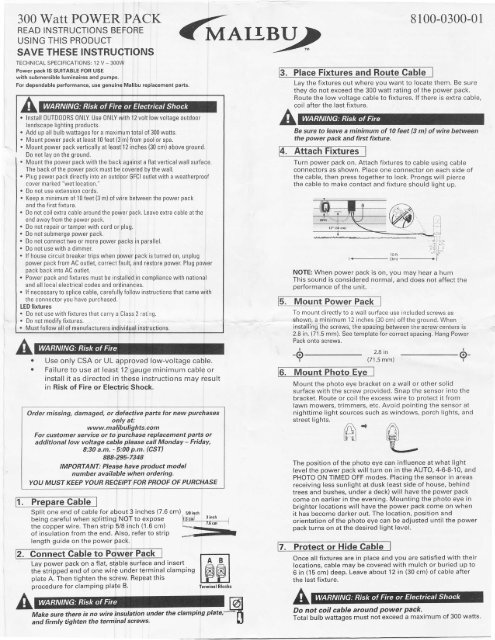
Split one end of cable <strong>for</strong> about 3 inches (7.6 cm). y6;n"1'<br />
beinscarefulwhensplittins-*9l1":tf:::, h.r*t--ffi_--l<br />
the copper wire. Then strip 5/8 inch (1.6 cm)<br />
of insulation from the end. Also, refer to strip<br />
length guide on the power pack.<br />
nect Cable to<br />
Lay power pack on a flat. stpble surface and insert<br />
the stripped end of one wirb under terminal clamping<br />
plate A. Then tighten the screw. Repeathis<br />
procedure <strong>for</strong> clamPing Plate B.<br />
Teminal Blocks<br />
LwMake sure there is no wire insulation under the clamping plate,-tl<br />
and firmly tighten the terminal screws'<br />
6nurg<br />
Use only CSA or UL approved low-voltage cable.<br />
Failure to use at least 12 gauge minimum cable or<br />
install it as directed in these instructions may result<br />
in Risk of Fire or Electric Shock.<br />
Order missing, damaged, or defective parts <strong>for</strong> new purchases<br />
only at:<br />
www.malibulights.com<br />
For customer service or to purchase replacement parts or<br />
additional low voltage cable please call Monday - Friday,<br />
8:30 a.m. - $:00 p.m. (CST)<br />
888-295-7348<br />
IMPORTANT: Plea$e have product model<br />
number available when ordering.<br />
YOU MUST KEEP YOUR REOEIPT FOR PBOOF OF PURCHASE<br />
Cable<br />
U<br />
3. Place Fixtures<br />
Lay the fixtures out where you want to locate them. Be sure<br />
they do not exceed the <strong>300</strong> watt rating of the power pack.<br />
Route the low voltage cable to fixtures. lf there is extra cable,<br />
coil after the.last fixture.<br />
Be sure to leave a minimum of 10 feet (3 m) of wire between<br />
the power pack and first fixture.<br />
A<br />
Turn power pack on. Attach fixtures to cable using cable<br />
connectors as shown. Place one connector on each side of<br />
the cable. then press together to lock. Prongs will pierce<br />
the cable to make contact and fixture should light up.<br />
I<br />
-@<br />
I<br />
I<br />
o-<br />
I<br />
Mount the photo eye bracket on a wall or other solid<br />
surface with the screw provided. Snap the sensor into the<br />
bracket. Route or coil the excess wire to protect it from<br />
lawn mowers, trimmers, etc. Avoid pointing the sensor at<br />
nighttime light sources such as windows, porch lights, and<br />
street lights.<br />
,/n\ r<br />
ld-ro I<br />
[ml<br />
The position of the photo eye can influence at what light<br />
level the power pack will turn on in the AUTO, 4-6-8-10, and<br />
PHOTO ON TIMED OFF modes. Placing the sensor in areas<br />
receiving less sunlight at dusk (east side of house, behind<br />
trees and bushes, under a deck) will have the power pack<br />
come on earlier in the evening. Mounting the photo eye in<br />
brighter locations will have the power pack come on when<br />
it has become darker out. The location, position and<br />
orientation ofthe photo eye can be adiusted until the power<br />
pack turns on at the desired light lel,el.<br />
Once all fixtures are in place and you are satisfied with their<br />
locations, cable may be covered with mulch or buried up to<br />
6 in (15 cm) deep. Leave about 12 in (30 cm) of cable after<br />
the last fixture.<br />
A<br />
""\iti.:<br />
t'l"nl+(3mt+l'<br />
.:Elnl<br />
NOTE: When power pack is on, you may hear a hum<br />
This sound is considered normal. and does not affect the<br />
per<strong>for</strong>mance of the unit.<br />
Pack<br />
To mount directly to a wall surface use included screws as<br />
shown, a minimum 12 inches (30 cm) off the ground. When<br />
installing the screws, the spacing between the screw centers is<br />
2.8 in. (71.5 mm). See template <strong>for</strong> correct spacing. Hang Power<br />
Pack onto screws.<br />
Do not coil cable around power pack.<br />
Total bulb wattages must not exceed a maximum of <strong>300</strong> watts.<br />
lofr<br />
2.8 in<br />
(/ r.5 mm,<br />
8100-0<strong>300</strong>-0
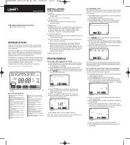
This power pack features ree automatic methods to turn on<br />
and off:<br />
1. A remote photo eye t at senses the light level. There is<br />
a 15 secon delav bu into the photo eye to avoid being<br />
triggered by lightning r other light sources.<br />
2. Atimer.<br />
3. A clock.<br />
The power pack operation Jes use these three methods in<br />
different combinations. To the mode, open the door to the<br />
power pack controls. The clock display and the AM/PM<br />
indicator will be lit if the pack is plugged in. lf the LEDs<br />
are not lit, then plug in the pack cord into the GFCI<br />
outlet.<br />
The clock is only required thE TIMER ANd PHOTO ON<br />
TIMED OFF modes. The cl is ignored <strong>for</strong> any of the other<br />
modes and does not need be set. To set the clock:<br />
Hold down the CLOCK while pressing either<br />
theAorvbutton. while holding down the<br />
CLOCK button will the displayed time. Pressing V<br />
while holding down the button will decrease the<br />
time displayed. Holding tl'ie orvbutton down <strong>for</strong> several<br />
seconds will speed up the in the display. Releasing<br />
the CLOCK button will set lthe clock time. Note the AM/PM<br />
LED indicators to get the cprrect time of day. This clock<br />
does NOT have a daylight jsavings time function. The clock<br />
time will manually need td be adjusted twice a year <strong>for</strong><br />
those changes.<br />
To change the operation modes of the power pack, turn the<br />
knob to point at the desired rhode. The selected mode will<br />
light up. 1<br />
33O<br />
9.<br />
To set the TIMED OFF clock, the knob needs to be turned<br />
to TIMER, then hold down the TTMED OFF button while<br />
pressing either the.t orv button. pressingAwhile holding<br />
down the TIMED OFF button will advance the displayed<br />
time. PressingVwhile holding down the TIMED OFF'button<br />
will decrease the time displayed. Holding the orybutton<br />
down <strong>for</strong> several seconds will speed up ihe change in the<br />
display. Releasing the TIMED OFF button will set ihe time.<br />
Note the AM/PM LED indicators to get the correct time of<br />
oaY,<br />
PHOTO ON TIMED OFF - The power pack turns on at dusk.<br />
The power pack will turn off when the clock reaches the<br />
TIMED OFF time. This mode will turn the power pack off at<br />
the same time every night regardless of how light or dark it<br />
is. The power pack and lights will be on from dusk to the<br />
TIMED OFF time,<br />
To set the TIMED OFF clock, the knob needs to be turned<br />
to PHOTO ON / TIMED OFF, then hold down rhe TIMED<br />
OFF button while pressing either the^, ory button.<br />
PressingAwhile holding down the TIMED OFF button will<br />
advance the displayed time. Pressingvwhile holding<br />
down the TIMED OFF button will decrease the time \<br />
displayed. Holding the orvbutton down <strong>for</strong> several \<br />
seconds will speed up the change in the display. Releasing \<br />
the TIMED OFF button will set the time. Note the AM/PM<br />
LED indicators to get the correct time of day.<br />
The TIMED ON clock does not work in the PHOTO ON TIMED<br />
OFF mode. lt does not matter what time it is set at. Close the<br />
door to the control panel after the mode has been selected.<br />
lf the wires to photo eye are cut or broken, the photo eye can<br />
be replaced. Unscrew the connector cover from the power<br />
pack and pull the bi-pin connector out of the mating socket.<br />
OFF - Power Pack is off. Lightg are off.<br />
ON - Power pack is on all the !ime, Use this mode when<br />
installing the light fixtures to {nsure a good connection.<br />
AUTO - Power pack turns on at dusk, turns off at dawn. The<br />
lights will be on all night. There is a 15 second delay from<br />
when the photo eye determinQs darkness and the power pack<br />
turns on.<br />
I<br />
4 - 6 - 8 - 10 - Power pack turns on at dusk and turns off<br />
automatically atter 4,6, 8 or 10 hours. There is a 15 second<br />
delay from when the photo eyd determines darkness and the<br />
power pack turns on.<br />
TEST - Use this mode to test rlie photo eye and power pack<br />
operation. Covering the photo pye turns on the power pack.<br />
Uncovering the photo eye durifrg the daytime or shining a<br />
bright light onto the photo eye Jwill turn off rhe power pick.<br />
Note that there is no 15 secondl delay in this mode.<br />
TIMER - The power pack turns qn when the clock reaches the<br />
TIMED ON time. The power pa(k will turn off when the clock<br />
reaches the TIMED OFF time. Tfris mode will turn the power<br />
pack on and off at the same timles everyday regardless of<br />
how light or dark it is. The powrbr pack and liqhts will be on<br />
from the TIME ON rime to the TINIED OFF tirie.<br />
To set the TIMED ON clock, tlne knob needs to be turned<br />
to TIMER, then hold down thd TTMED ON button while<br />
pressing either the orVbuttjon. pressing while holding<br />
down the TIMED ON button vtill advance the displayed -<br />
time. Pressing v while holdin$ down the TIMED ON.button<br />
will decrease the time displaylpd. Holding theAorvbutton<br />
down <strong>for</strong> several seconds willl speed up the change in the<br />
display. Releasing the TIMED 0N button will set the time.<br />
Note the AM/PM LED indicatofs to get the correct time of<br />
dav.<br />
l<br />
The replacement part is inserted into the socket and the cap<br />
is screwed back onto the socket to provide a water tight<br />
connection. Note that the bi-pin connector is polarized and<br />
can be inserted into the socket only one way. The photo eye<br />
operation can be tested by turning the power pack mode to<br />
TEST.<br />
The replacement photo sensor part 3150-0<strong>300</strong>-92 can be<br />
glqgfed by calling 888-295-7328 from 8:30 a.m. - b:00 p.m.<br />
(csr).<br />
NOTE: Circuit breaker may need to be reset if the power<br />
pack is not working.