Transmit Combiners - Aspen Electronics
Transmit Combiners - Aspen Electronics
Transmit Combiners - Aspen Electronics

You also want an ePaper? Increase the reach of your titles
YUMPU automatically turns print PDFs into web optimized ePapers that Google loves.
T-Pass <strong>Combiners</strong><br />
Technical Specifications<br />
215-300 MHz<br />
Model Numbers/<br />
Frequency<br />
Cavity Type and<br />
Diameter<br />
Maximum Continuous<br />
<strong>Transmit</strong> Power<br />
Isolator Load Pwr<br />
(Continous) [Note 3]<br />
Min Tx-Tx Separation<br />
@ Cavity Loss<br />
Typical Tx-Tx Isolation<br />
@ Min Separation<br />
Typical Antenna - TX<br />
Isolation<br />
Typical TX Noise<br />
Suppression<br />
Normal Input<br />
Impedance<br />
Maximum Input<br />
Return Loss (VSWR)<br />
Temperature Range<br />
Connectors, Input &<br />
Antenna<br />
Notes:<br />
73-54A-01-2B-nn<br />
73-54A-01-2D-nn<br />
73-54A-05-2B-nn<br />
73-54A-05-2D-nn<br />
73-54A-01-2B-nn<br />
73-54A-01-2D-nn<br />
73-54A-05-2B-nn<br />
73-54A-05-2D-nn<br />
73-54A-01-2B-nn<br />
73-54A-01-2D-nn<br />
73-54A-05-2B-nn<br />
73-54A-05-2D-nn<br />
73-54A-01-2B-nn<br />
73-54A-01-2D-nn<br />
73-54A-05-2B-nn<br />
73-54A-05-2D-nn<br />
215-300 MHz<br />
Quarterwave, 6.625” (168<br />
mm)<br />
Quarterwave, 10”<br />
(254 mm)<br />
See table on right<br />
5W/25W<br />
5W/100W<br />
5W/25W<br />
5W/100W<br />
125 kHz @ -1.5 dB; 75 kHz<br />
@ -2.5 dB<br />
-70 dB<br />
-60 dB<br />
Depends on cavity loss<br />
(See curves below)<br />
50 ohms<br />
-20 dB (1.22:1)<br />
-30 to +60 Celsius<br />
Mechanical Mounting Peg Rack ®<br />
Mounting Options<br />
[Notes 4,5]<br />
Maximum Channels<br />
Per Rack [Notes 4]<br />
Dimensions [Notes 6]<br />
Weight, lb (Kg) -<br />
Basic Single-Channel<br />
Weight, lb (Kg) -<br />
Expansion Channel<br />
Assy<br />
73-54A-01-2B-nn<br />
73-54A-01-2D-nn<br />
73-54A-05-2B-nn<br />
73-54A-05-2D-nn<br />
73-54A-01-2B-nn<br />
73-54A-01-2D-nn<br />
73-54A-05-2B-nn<br />
73-54A-05-2D-nn<br />
73-54A-01-2B-nn<br />
73-54A-01-2D-nn<br />
73-54A-05-2B-nn<br />
73-54A-05-2D-nn<br />
73-54A-01-2B-nn<br />
73-54A-01-2D-nn<br />
73-54A-05-2B-nn<br />
73-54A-05-2D-nn<br />
73-54A-01-2B-nn<br />
73-54A-01-2D-nn<br />
73-54A-05-2B-nn<br />
73-54A-05-2D-nn<br />
1. -nn in model number represents the number of channels.<br />
2. Consult factory on T-Pass multicouplers for frequencies below 215 or above<br />
300 MHz.<br />
3. Models available with 5W/60W loads. Same specifications as 25W and 100W<br />
models, except load power.<br />
4. -MC option reduces maximum number of channels to ten 10-inch or twelve<br />
6.625-inch channels per rack.<br />
5. -LR systems are tuned and tested on customer frequencies, then disassembled for<br />
shipping.<br />
6. Rack depth with cavity tuning rods at maximum frequency. Rod travel is<br />
approximately 3.9” (99 mm).<br />
N<br />
MC: 19” rackmount adapter<br />
plates, 17.5” high<br />
LR: System supplied<br />
without Peg Rack ®<br />
15<br />
15<br />
12<br />
12<br />
65.25”Hx24”Wx26.4”D<br />
(1659x610x671mm)<br />
79.5”Hx24”Wx28.4D<br />
(2019x610x721mm)<br />
34 (17.2)<br />
35 (17.7)<br />
39 (19.9)<br />
40 (20.4)<br />
14 (7.2)<br />
15 (7.7)<br />
18 (9.5)<br />
19 (10)<br />
Typical Insertion Loss and Maximum Input Power<br />
73-54A-01-Series Systems (6.625” Cavity Diameter)<br />
Tx-Tx Cavity Maximum Loss (dB) vs. No. of channels<br />
Separation Loss Power 2 4 8 12<br />
1 MHz -1.5 dB 150 W -2.6 -2.7 -3.0 -3.3<br />
250 kHz -1.5 dB 150 W -2.9 -3.4 -3.8 -4.1<br />
175 kHz -1.5 dB 150 W -3.1 -3.9 -4.5 -4.9<br />
125 kHz -2.0 dB 135 W -3.6 -4.4 -4.9 -5.3<br />
100 kHz -2.5 dB 115 W -4.1 -4.5 -5.4 -5.8<br />
73-54A-05-Series Systems (10” Cavity Diameter)<br />
Tx-Tx Cavity Maximum Loss (dB) vs. No. of channels<br />
Separation Loss Power 2 4 8 12<br />
1 MHz -1.5 dB 150 W -2.6 -2.7 -2.9 -3.1<br />
250 kHz -1.5 dB 150 W -2.8 -3.1 -3.4 -3.7<br />
150 kHz -1.5 dB 150 W -3.4 -3.8 -4.3 -4.6<br />
100 kHz -2.0 dB 150 W -3.6 -4.5 -5.1 -5.5<br />
75 kHz -2.5 dB 130 W -4.2 -5.1 -5.8 -6.2<br />
Attenuation (dB)<br />
Attenuation (dB)<br />
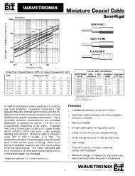
73-54A-01-Series Systems<br />
6.625” Diameter Quarterwave, Fo=124 MHz<br />
Offset from Fo (MHz)<br />
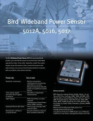
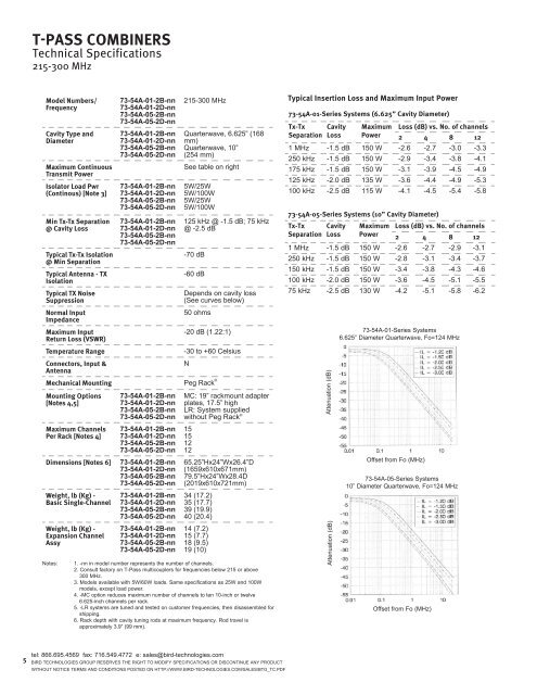
73-54A-05-Series Systems<br />
10” Diameter Quarterwave, Fo=124 MHz<br />
Offset from Fo (MHz)<br />
5<br />
tel: 866.695.4569 fax: 716.549.4772 e: sales@bird-technologies.com<br />
Bird Technologies Group RESERVES THE RIGHT TO MODIFY SPECIFICATIONS OR DISCONTINUE ANY PRODUCT<br />
WITHOUT NOTICE Terms and Conditions posted on http://www.bird-technologies.com/sales/btg_tc.pdf