2nd Edition 2nd Edition - Aspen Electronics
2nd Edition 2nd Edition - Aspen Electronics
2nd Edition 2nd Edition - Aspen Electronics
- No tags were found...

Create successful ePaper yourself
Turn your PDF publications into a flip-book with our unique Google optimized e-Paper software.
TEST & MEASUREMENTCATALOGUE2 nd <strong>Edition</strong><strong>Aspen</strong> <strong>Electronics</strong> Limited
About <strong>Aspen</strong> <strong>Electronics</strong> LtdThank Thank you you for for taking taking the the time time to to read read this this second second edition edition of of the the<strong>Aspen</strong> <strong>Electronics</strong> Ltd LtdTest Test & Measurement Equipment catalogue.We We have have now now added added even even more more products suitable for for those those working in in Broadcast,Satellite Communications, Aerospace, Telecommunications and and Mobile Mobile Radio Radio Applications,along along with with other other markets such such as as Automotive, Education and and Medical <strong>Electronics</strong>.Again Again we we represent one one of of the the widest widest ranges ranges of of equipment, all all available from from one one source. source.<strong>Aspen</strong> <strong>Aspen</strong> <strong>Electronics</strong> Ltd Ltd has has been been supporting the the UK UK electronics industry since since 1974, 1974,supplying Test Test & Measurement Equipment and and RF RF & Microwave Components. We Wecontinue to to build build on on our our reputation of of providing consultative sales sales support support to to all all of of our ourcustomers no no matter matter what what their their requirement. The The cornerstone of of this this philosophy is isour our desire desire to to discuss discuss your your application knowing that that every every customer counts. counts. Our Ourknowledgeable Sales Sales Team Team are are always always available* to to answer answer your your call call in in person person (no (noautomated switchboards here), here), plus plus our our Field Field Sales Sales Team Team are are available to to meet meet with withyou you at at your your facility facility to to discuss discuss your your needs needs and/or and/or offer offer a demonstration, face-to-face.This This personal approach to to our our customers extends to to all all commercial aspects. We We are aremore more than than happy happy to to discuss your your requirement for for a competitive quote quote when when ordering.Our Our well well equipped Service Service Department are are always always on on hand hand to to help help with with post post sales salessupport, including Service, Repair Repair & Calibration.<strong>Aspen</strong> <strong>Aspen</strong> <strong>Electronics</strong> Ltd Ltd is is an an ISO ISO 9001:2000 approved Company and and as as such, such, we we are aremore more than than happy happy to to receive receive customer feedback about about any any subject.Howard Venning, Managing Director<strong>Aspen</strong> <strong>Aspen</strong> <strong>Electronics</strong> Limited Limited**OurOurSalesSalesOfficeOfficeisisopenopenfromfrom8.15am8.15amtoto5.15pm.5.15pm.PleasePleasecall:call:020020886888681311.1311.OurOure-maile-mailaddressaddressisissales@aspen-electronics.comsales@aspen-electronics.com
Product IndexOscilloscopesPage No.Digital Oscilloscopes 4Mixed Signal Oscilloscopes 12PC Based Digital Oscilloscopes 13PC Based Logic Analysers 15Handheld Oscilloscopes 16Combined Digital & Analogue Oscilloscopes 18Analogue Oscilloscopes 20RF AnalysersBench Spectrum Analysers 25Handheld Spectrum Analysers 34 & 136Logging Spectrum Monitor/Analyser 39Vector Network Analyser 40Site & Antenna Analysers 42Microwave Antenna Alignment 44Protek Handheld Range 45Time & Frequency AnalysisTimer, Counter, Analysers inc. Microwave 48Modulation Domain Analysis Software 55High Stability Frequency Standards 56Distribution Amplifiers 58Universal Counters 59RF Power MeasurementRF Power Meters 61Bird RF Power Sensors 64Remote & USB RF Power Meters 67Thruline ® Power Meters 69Antenna Monitors 70Power SuppliesProgrammable AC Power Supplies 71Programmable DC Power Supplies 75Programmable Electronic Loads 87Bench DC Power Supplies 90Signal SourcesRF Generators 96Broadcast Signal Generators 99Function/Arbitrary Waveform Generators 101Function Generators 104Audio Generators 112General PurposeBench Multimeters 113Handheld Multimeters 118Component Testers - LCR & Milli-Ohm 119Hi-Pot/Safety Testers 122AC Power Meter 125Handheld Instruments 126Thermal Platforms 130AccessoriesAdaptors, Attenuators, Bias Tees, CableAssemblies, Couplers & Splitters, Filters,Isolators & Circulators, Loads &Terminations, Phase Shifters, ScopeProbes, Standard Gain Horn Accessories 131Repair, Service & Calibration 135www.aspen-electronics.com sales@aspen-electronics.comMANY PRODUCTS AVAILABLE TO BUY ONLINE, SEE OUR WEB-STORE: www.aspen-electronics.com/shop.html 3
Digital OscilloscopesWaveSurfer ® XS Series• 200MHz ~ 1GHz Bandwidth.• 2.5GS/s (5GS/s Interleaved).• Long Capture Time.• 10.4” Touchscreen Display.• Mixed Signal Option with Serial Trigger & Decode.104Xs62Xs64Xs42Xs44Xs24XsAcquisitionBandwidthRise TimeInput Channels200MHz1.75ns4400MHz875ps4400MHz875ps2600MHz625ps4600MHz625ps21GHz400ps4Sample Rate(Single-Shot)2.5 GS/s2.5 GS/s2.5 GS/s2.5 GS/s2.5 GS/s2.5 GS/s(5GS/sinterleaved)Sample Rate (RIS Mode)Standard Record LengthStandard Capture Time50 GS/s2.5 Mpts/Ch (All Channels), 10Mpts/ch with VL OptionUp to 1ms at Full Sample Rate on All 4 ChannelsVerticalVertical ResolutionVertical Sensitivity (V/div)Vertical (DC Gain) Accuracy8 bits2mV/div – 10V/div (1MΩ); 2mV/div-1V/div (50Ω)±1.0% of Full Scale (Typical); ±1.5% of Full Scale ≥ 10mV/divBW Limit20MHz20MHz, 200MHzMaximum Input Voltage50Ω: 5Vrms, 1MΩ: 400V Max, (DC + Peak AC ≤5kHz)50Ω:5Vrms,1MΩ: 250VMax, (DC +Peak AC≤10kHz)Input CouplingAC, DC, GND (DC & GND for 50Ω)Input Impedance1MΩ, 16pF, or 50Ω1MΩ,20pF, or50ΩProbing SystemBNC or ProBusProbesOne PP009 (5mm) per Channel (Standard)OnePP011(5mm) PerChannel(Std)4Tel: +44 (0)20 8868 1311 Fax: +44 (0)20 8866 65961-3 Kildare Close, Eastcote, Ruislip, Middlesex HA4 9UR
104Xs62Xs64Xs42Xs44Xs24XsTimebaseRangeAccuracy200ps/div ~ 1000s/div (Roll Mode from 500ms/div ~ 1000s/div)≤5ppm @ 25°C (Typical) (≤10ppm @ 5-40°C)TriggerTrigger ModesTrigger SourcesTrigger CouplingPre-Trigger DelayPost-Trigger DelayTrigger Hold-OffInternal Trigger Level RangeExternal Trigger RangeStandard TriggersAdvanced Triggers(WS Xs-ADVTRIG Opt.)Normal, Auto, Single & StopAny Input Channel, External, Ext/10, or Line; Slope & Level Unique to EachSource (Except for Line Trigger)DC, AC, HFRej, LFRej0-100% of Full Scale0-10,000 Divisions1ns to 20s or 1 ~ 1,000,000,000 Events±4.1 div from centreEXT/10 ± 4V; EXT ± 400mVEdge, Glitch, Width, Logic (Pattern), TV-Composite VideoRunt, Slew Rate, Interval (Signal or Pattern), Dropout,Qualified (State or Edge)AnalysisMeasurementsZoomStandard MathExtended Math(WS Xs-MATHSURF Opt.)Amplitude, Area, Base (Low), Delay, Duty, Fall Time (90% ~ 10%), Fall Time(80% ~ 20%), Frequency, Maximum, Mean, Minimum, Overshoot+, Overshoot-,Period, Peak-Peak, Phase, Rise Time (10 ~ 90%), Rise Time (20% ~ 80%), RMS,Skew, Standard Deviation, Top (High), Width+, Width-Zoom Available Using Quick Zoom Button, Touch Screen or MouseSum, Difference, Product, Ratio, FFT (Up to 25Kpts with Power Spectrum Output& Rectangular VonHann & FlatTop Windows). One Math Function may beDefined at a Time.Adds Additional Math Functions: Absolute Value, Averaging (Summed andContinuous), Derivative, Envelope, Enhanced Resolution (to 11bits), Floor,Integral, Invert, Reciprical, Roof, Square, Square-root. Also Adds Chaining ofTwo Maths Functions, Rescaling to Different Units & 1Mpts FFTOPTIONS & ACCESSORIESWSXs-VL10Mpts/Ch (for 4ch Models).WSXs-VL210Mpts/Ch (for 2ch Models).WSXs-ADVTRIGAdvanced Trigger Package.WSXs-MATHSURFExtended Math Package.WSXs-HardcaseHard Carrying Case.WSXs-SoftcaseSoft Carrying Case.For Other Options, Please Contact Us.www.aspen-electronics.com sales@aspen-electronics.comFOR EQUIPMENT CALIBRATION DETAILS, CALL OUR SERVICE DEPARTMENT TODAY… 5
Digital OscilloscopesWaveJet ® 300 Series• 100MHz ~ 500MHz Bandwidth.• 500k Memory.• 1GS/s Sample Range (2GS/s Interleaved).• 7.5” Colour Display.• Auto Measurements inc. FFT.• USB Interface as Standard.WaveJet352WaveJet354WaveJet332WaveJet334WaveJet322WaveJet324WaveJet312WaveJet314AcquisitionBandwidthRise Time100MHz3.5ns200MHz1.75ns350MHz1ns500MHz750psInput Channels42424242DisplaySampling Rate (Single-Shot)Sampling Rate (RIS)Peak Detect PeriodMemory LengthCapture Time1GS/s7.5” Colour Flat-Panel TFT-LCD, 640 x 480 VGA2GS/s (Interleaved), 1GS/s (All Channels)100GS/s1ns500kpts/Ch (All Channels)500µs at 1GS/s, 250µs at 2GS/sVerticalVertical Resolution8bitVertical Sensitivity2mV/div-10V/div2mV/div-10V/div,2mV/div-2V/div (50Ω)Vertical (DC) Gain Accuracy± (1.5% + 0.5% of Full Scale)BW Limiting FiltersMaximum Input VoltageInput CouplingInput Impedance20MHz400V Cat 1GND, DC 1MΩ, AC 1MΩ1MΩ ± 1.5%, 20pF20MHz, 200MHz400V Cat 1, 5Vrms (50Ω)GND, DC 1MΩ, AC 1MΩ, DC 50Ω1MΩ ± 1.5%, 16pF; 50Ω ±1.5%Probing SystemBNC with Probe Sense RingProbesPP010 (One Per Channel)PP006A (One Per Channel)TimebaseTimebase Range5ns/div-50s/div2ns/div-50s/div1ns/div-50s/div500ps/div-50s/divTriggeringAnalysisGeneralRoll ModeTimebase AccuracyTrigger TypesMeasurementsZoomMath FunctionsDimensionsWeight50ms/div-50s/div (100kS/s Maximum)10ppm (Typical)Edge, Glitch, Period, Pulse Count, TVBase, Cycle Mean, Cycle RMS, Duty Cycle, Fall Time (90% ~ 10%), Fall Time(80% ~ 20%), Frequency, Integral, Maximum, Mean, Minimum,Number of + Pulses, Number of - Pulses, Overshoot +, Overshoot -, Peak-Peak,Period, Pulse Width+, Pulse Width-, Rise Time (10% ~ 90%),Rise Time (20% ~ 80%), RMS, Skew, Skew @ Level, Top, Top-BaseFront Panel, Quick Zoom Buttom (Zooms All Waveforms in Separate Grid)Sum, Difference, Product, FFT (Up to 8Kpts with RectangularVonHann or FlatTop)190mm x 285mm x 102mm3.2kgOPTIONS & ACCESSORIESWJ-GPIBWJ-LANGPIB Interface for WaveJet 300 Series.10/100 Base-T Interface for WaveJet 300 Series.6Tel: +44 (0)20 8868 1311 Fax: +44 (0)20 8866 65961-3 Kildare Close, Eastcote, Ruislip, Middlesex HA4 9UR
Digital OscilloscopesGDS-2000 Series• 200/100/60MHz Bandwidth.• 2 or 4 Input Channels.• 1GSa/s Real Time and 25GSa/sEquivalent Time Sampling.• Maximum 25k Points Record Length.• High Brightness 5.6” TFT Colour Display.• USB Memory Stick Data Storage.AVAILABLETO BUY ONLINEGDS-2062GDS-2064GDS-2102GDS-2104GDS-2202GDS-2204VerticalChannelsBandwidthRise Time2/4DC ~ 60MHz (-3dB)5.8ns2/4DC ~ 100MHz (-3dB)3.5ns2/4DC ~ 200MHz (-3dB)1.75nsTriggerEXT TriggerHorizontalX-Y ModeSensitivityAccuracyInput CouplingInput ImpedancePolarityMaximum InputWaveform OperatorsOffset RangeBandwidth LimitSourcesModesCoupling TypesCoupling SensitivityRangeSensitivityInput ImpedanceMAX InputRangeModesAccuracyPre-TriggerPost-TriggerX-Axis InputY-Axis InputPhase Shift2mV/div ~ 5V/div (1-2-5 increments)±(3% x |Readout| + 0.05 div x Volts/div +0.8mV)AC, DC & Ground1MΩ ± 2%, 16pFNormal & Invert300V (DC + AC Peak), CATII+, -, FFT2mV/div ~ 20mV/div: ±0.5V; 50mV/div ~ 200mV/div: ±5V;500mV/div ~ 2V/div: ±50V; 5V/div: ±300V20MHz (-3dB)CH1, CH2, Line, EXT (2CH Models), CH3, CH4 (4CH Models)AUTO, NORMAL, SINGLE, TV, Auto-Level, Edge, Pulse Width Time-Delay(2CH Models), Event-Delay (2CH Models)AC, DC, LF Rej, HF Rej, Noise Rej≤25MHz: ≤0.5div or 5mV>25MHz: ≤1div or 10mV±15V≤30MHz: 30MHz:
GDS-2204GDS-2202GDS-2104GDS-2102GDS-2064GDS-2062Signal AcquisitionCursors &MeasurementControl PanelDisplayInterfacePower SourceMiscellaneousGeneralReal Time Sample RateEquivalent Sample RateVertical ResolutionRecord LengthAcquisition ModePeak DetectionAverageVoltage FunctionsTime FunctionsDelay FunctionsCursor FunctionsAuto CounterAutosetSave Setup MemoriesSave Waveform MemoriesTypeDisplay ResolutionDisplay GraticuleDisplay BrightnessUSBRS-232 InterfaceGPIB Interface (Option)Go/NoGo OutputLine Voltage RangeBattery Power (Option)Online HelpReal Time ClockDimensionsWeight1GSa/s max25GSa/s E.T. max8 Bits25kPts maxSample, Peak Detect, Average, Accumulate10ns2, 4, 8, 16, 32, 64, 128, 256 AveragesVpp, Vamp, Vavg, Vrms, Vhi, Vlo, Vmax, Vmin, Rise Preshoot/Overshoot,Fall Preshoot/OvershootFreq, Period, Rise Time, Fall Time, Positive Width, Negative Width,Duty CycleEight Delay MeasurementsVoltage Difference (∆V), Time Difference (∆T)Resolution : 6 DigitsAccuracy : ±2%Signal Source: Trigger (Except Video Trigger Mode)Vertical Scale, Horizontal Scale & Trigger Level Set AutomaticallyUp to 20 SetupsUp to 24 Waveforms5.6” High Brightness TFT LCD234 x 3208 x 10 Divisions ; 8 x 12 Divisions (Menu Off)AdjustableBoth Host & Device Modes Supported, USB 2.0 Full SpeedDB 9-pin Male DTE RS-232 InterfaceFully Programmable, IEEE 488.25V MAX / 10mA TTL Open Collector OutputAC 100V ~ 240V, 48Hz ~ 63HzBattery : 11.1V Li-Ion Battery PackCharge Time: 8 Hours (with Power On)Operating Time: 4 Hours, Subject to Operating ConditionsAvailableTime, Date/Time for Saved Data254mm (D) x 142mm (H) x 310mm (W)4.3kgAccessories IncludedOption 01Option 02GSC-005GRA-405OPTIONS & ACCESSORIESUser Manual, Power Cable, 2/4 60/100/250MHz Probes.GPIB Interface.Battery Power Option.Soft Carry Case.Rack Adapter Panel.8Tel: +44 (0)20 8868 1311 Fax: +44 (0)20 8866 65961-3 Kildare Close, Eastcote, Ruislip, Middlesex HA4 9UR
Digital Oscilloscopes3000 Series• 150MHz Bandwidth, 125k Memory.• Mouse Control.• USB Memory Stick Storage & Battery Options.AVAILABLETO BUY ONLINEWENS3001WENS3002BandwidthSample RateInputVerticalHorizontalTriggerAcquisitionMeasurementFunctionsDisplayInterfaceStandardAccessoriesGeneralReal SamplingRepetitive SamplingInput ChannelsInput CouplingInput ImpedanceProbe Attenuation FactorsMax. Input VoltageAnalogue Bandwidth LimiterVertical ResolutionRangeOffset RangeVertical AccuracyRise Time at Input BNCRangeTime Base AccuracyPosition RangeTrigger SourceTrigger CouplingTrigger ModeExternal Trigger RangeTrigger SensitivityRecord LengthAcquisition ModePeak DetectionCursorAutomatic MeasurementSave/RecallZoomXY ModeDisplay DeviceExternal Control DeviceInternal USB Flash Memory SysBatteryRS-232 / Parallel (Printer) / USBDimensionsWeight150MHz150MHz200MS/s, Single Channel Mode; 100MS/s per Channel50GS/s2 ChannelsDC, AC, GND1MΩ ± 1%, 20pF ± 3pF1X, 10X, 100X, 1000X300Vpk-pk, CAT II20MHz8-Bit2mV/div ~ 5 V/div (1, 2, 5 Step)±50 div±2%2.3ns1 ns/div ~ 10 s/div± 0.01%Pre Trigger: 20 div Maximum; Post Trigger: 1000 divCH1, CH2, AC Line, EXTDC, AC, HF REJ, LF REJ, Noise REJEdge, Pulse Width, Delay, Pattern, TV± 15V0.2 div125kbytes/channelSample, Peak Detect, Envelope, Average10 nsVoltage Difference (ΔV) & Time Difference (ΔT) Between TwoCursors, Reciprocal of ΔTFrequency, Period, Mean, Pk-Pk, Cycle RMS, Min, Max, High,Low, Duty, Delay, Rise Time, Fall Time, Positive Overshoot,Negative Overshoot5 Waveforms, 10 Settings (Expandable withFlash Memory Systems)Direct Time / Volt ConversionX Axis Channel Input – Y Axis Channel Input5.7” 320 x 240Mono LCDExternal Mouse PortOptionOptionStandard5.7” 320 x 240Colour LCDPower Cable x 1, User’s Manual x 1, Passive Probe x 2USB PC Software & Cable x 1, RS-232 PC Software & Cable x 1338mm (W) x 155mm (H) x 200mm (D)3.9kg Without BatteryWENS-3001Option FWENS-3APORDERING INFORMATION150MHz Mono Display.WENS-3002USB Flash Memory Stick Option.Option B500MHz Active Probe.150MHz Colour Display.Internal Battery System & Battery Pack.www.aspen-electronics.com sales@aspen-electronics.comIF YOU HAVE A REQUIREMENT THAT IS NOT SHOWN IN THIS CATALOGUE, PLEASE CONTACT US… 9
Digital OscilloscopesGDS-800 Series• 60, 100, 150 & 250MHz Bandwidth Models Available.• 125k Memory.• Colour or Monochrome Display.• USB & GPIB Available.• 15 Auto Measurements.AVAILABLETO BUY ONLINEGDS-840SGDS-840CGDS-820SGDS-820CGDS-810SGDS-810CGDS-806SGDS-806CDisplay SystemDisplay DeviceDisplay ContrastWaveform Display GraticuleDisplay ModeVertical SystemBandwidth (-3dB)Number of ChannelsRise TimeVertical ResolutionVertical Sensitivity & AccuracyInput CouplingInput ImpedancePolarityMaximum Voltage BetweenSignal & Common at Input BNCWaveform Math OperatorsOffset RangeBW LimitHorizontal SystemTime Base RangeTime Base ModeTime Base AccuracyDelay RangeSignal Acquisition SystemReal-Time Sample RateEquivalent Sample RateRecord LengthPeak DetectionAcquisition ModeAverageTriggerTrigger SourceModeCouplingSensitivityX-Y ModeX-Axis Input / Y-Axis InputPhase Shift5.7”LCD(Mono)250MHz< 1.4ns5.7”LCD(Colour)1MΩ ± 2%, ~ 18pFDC ~ 30MHz :0.5div or 5mV30MHz ~ 150MHz :1.5div or 15mV150MHz ~ 250MHz :2.0div or 20mV5.7”LCD(Mono)< 2.3ns5.7”LCD(Colour)< 3.5ns8-bit2mV ~ 5V, ± 3%AC, DC, Ground1MΩ ± 2%, ~ 22pF1MΩ ± 2%, ~ 18pFPositive & Negative300V (DC + AC Peak), CATIIDC ~ 30MHz :0.5div or 5mV 30MHz~ 150MHz : Approx.1.5div or 15mV5.7”LCD(Mono)CH 1 / CH 2± 3° at 100kHz5.7”LCD(Colour)Adjustable8 x 10 Divisions (8 x 12 with Menu Off)Dot, Vector, Accumulate150MHz2100MHzDC ~ 25MHz :Approx.0.5div or 5mV25MHz ~ 100MHz: Approx.1.5div or 15mV5.7”LCD(Mono)60MHz< 5.8ns5.7”LCD(Colour)CH1 + CH2, CH1-CH2, FFT2mV/div ~ 50mV/div: ± 0.5V; 100mV/div ~ 500mV/div: ± 5V ; 1V/div ~ 5V/div: ± 50V20MHz (-3dB)1ns/div ~ 10s/div (1-2-5 Increments); Roll Mode: 250ms/div ~ 10s/divMain, Window, Window Zoom, Roll, X-Y± 0.01%Pre-Trigger : 20 div Maximum; Post-Trigger: 1000 div100MS/s Maximum on Each Channel25GS/s E.T. Maximum on Each Channel125k/CH10ns (500ns/div ~ 0s/div)Sample, Peak Detect, Average2, 4, 8, 16, 32, 64, 128, 256CH1, CH2, Line, ExtAuto Level, Auto, Normal, Single, TV, Time Delay, Event Delay, Edge, Pulse WidthAC, DC, HF, LF, Noise RejectDC ~ 25MHz :Approx.0.5div or 5mV25MHz ~ 60MHz :Approx.1.5div or 15mV10Tel: +44 (0)20 8868 1311 Fax: +44 (0)20 8866 65961-3 Kildare Close, Eastcote, Ruislip, Middlesex HA4 9UR
GDS-806CGDS-806SGDS-810CGDS-810SGDS-820CGDS-820SGDS-840CGDS-840SCursor & MeasurementGeneralAuto Voltage MeasurementAuto Time MeasurementCursor MeasurementFrequency CounterReadout ResolutionFrequency RangeSignal SourceAdjustable Probe Compensation SignalFrequency RangeDuty CycleExternal TriggerRangeSensitivityInput ImpedanceMaximum InputControl Panel FunctionAutoSetSave RecallWaveform Trace Save/RecallInterfaceStandardOption 01Option 11Power SourceAccessoriesDimensionsWeightVpp, Vamp, Vavg, Vrms, Vhi, Vlo, Vmax, VminFreq, Period, Rise Time, Fall Time, Positive Width, Negative Width, Duty CycleVoltage Difference Between Cursors (Δ V), Time Difference Between Cursors (Δ T),Reciprocal in Hertz (1 / ΔT)6 DigitsAC Coupled, 20Hz ~ Rated Bandwidth; Resolution : 10HzAll Available Trigger Sources Except Pulse Width & Video Trigger Modes≤30MHz: ≤50mV;>30MHz: ≤100mV;1MΩ ± 2%, ~ 18pF≤30MHz: ≤50mV;>30MHz: ≤100mV1MΩ ± 2%, ~ 22pF≤25MHz: ≤50mV;>25MHz: ≤100mV≤25MHz: ≤50mV;>25MHz: ≤100mV“Autoset” Can Adjust Vertical (Volt/div), Horizontal (Sec/div) andTrigger Level AutomaticallyUp to 15 Sets of Measurement Conditions Can Be Saved & Recalled2 Sets of Waveform Data Can Be Saved & RecalledUSB, RS-232C, Printer Port,RS-232Go/NoGo OutputGPIB InterfaceGPIB InterfaceN/AUSB, Printer Port, Go/NoGo Output100V ~ 240V AC 47Hz ~ 63HzInstruction Manual x 1, Power Cord x 1GTP-250A Probe(10:1/1:1) x 2N/AN/AGTP-150A Probe(10:1/1:1) x 2310mm (W) x 142mm (H) x 254mm (D)4.1kg±15V1kHz ~ 100kHz in 1kHz Steps5% ~ 95% in 5% Steps1MΩ ± 2%, ~ 18pF300V (DC+AC Peak), CATIIGTP-100A Probe(10:1/1:1) x 2GTP-060A Probe(10:1/1:1) x 2310mm (W) x 142mm (H) x 254mm (D)3.8kgORDERING INFORMATIONGDS-840CGDS-840SGDS-820CGDS-820SGDS-810CGDS-810SGDS-806CGDS-806SOption 01Option 02Option 03Option 04Option 05Option 06Option 07Option 11250MHz, 2-Channel, Colour LCD Display DSO.250MHz, 2-Channel, Mono LCD Display DSO.150MHz, 2-Channel, Colour LCD Display DSO.150MHz, 2-Channel, Mono LCD Display DSO.100MHz, 2-Channel, Colour LCD Display DSO.100MHz, 2-Channel, Mono LCD Display DSO.60MHz, 2-Channel, Colour LCD Display DSO.60MHz, 2-Channel, Mono LCD Display DSO.GPIB Interface.RS-232C Cable, 9-Pin Female to 9-Pin, Null Modem For Computer.USB Cable, USB1.1 A-B Type Cable, 1800mm.GSC-005 Soft Carrying Case.GRA-405 Rack Adapter Panel.GTC-001 Instrument Cart, 450mm (W) x 430mm (D).GTC-002 Instrument Cart, 330mm (W) x 430mm (D).USB Interface, Printer Port, Go/NoGo Output.www.aspen-electronics.com sales@aspen-electronics.comOUR RANGE IS CONSTANTLY EXPANDING, SEE OUR WEBSITE FOR NEW PRODUCT DETAILS… 11
Mixed Signal OscilloscopesDS1000 Series• 2 Channel Oscilloscope, 16 Digital Channels.• Long Memory, 1MPts Max.• Bright TFT Colour Display.• USB Interface for USB Memory Stick & Printer.AVAILABLETO BUY ONLINEDS1102CDS1062CDS1042CDS1022CBandwidthMemory DepthNumber of ChannelsRealtime Sample RateEquivalent Sample RateRise TimeTimebase RangeX-Y Operation (Bandwidth)X-Y Operation (Phase Difference)Trigger ModesTrigger SourcesAccessories100MHz60MHz40MHz25MHz1MPts (Single CH), 512kPts (Dual CH)2CH + EXT Trig400MSa/s25GSa/s3.5ns5.8ns8.7ns14ns5ns ~ 50s10ns ~ 50s 20ns ~ 50s100MHz60MHz40MHz25MHz3 degreesEdge, Pulse, Slope, Video, AlternateCH1, CH2, Ext, Ext/5, AC LineProbe x 2 (x1, x10 Switchable), Power Cord, User ManualDS1022CDDS1042CDDS1062CDDS1102CDBandwidthMemory DepthNumber of ChannelsRealtime Sample RateEquivalent Sample RateRise TimeTimebase RangeX-Y Operation (Bandwidth)X-Y Operation (Phase Difference)Maximum Input VoltagePredefined ThresholdsTrigger ModesTrigger SourcesAccessoriesInput ImpedanceVertical SensitivityVertical ResolutionInput CouplingMaximum Input VoltageRoll RangeAuto MeasureCursor MeasureMathStorageI/ODisplayNet WeightDimensions100MHz60MHz40MHz25MHz1MPts (Single CH), 512kPts (Dual CH & Logic Analyser)2CH + EXT Trig + 16 Logic Analyser400MSa/s Scope, 200MSa/s (Logic Analyser)25GSa/s3.5ns5.8ns8.7ns14ns5ns ~ 50s10ns ~ 50s 20ns ~ 50s100MHz60MHz40MHz25MHz3 degreesLogic Analyser: 40V (DC + AC Peak)TTL = 1.4V, CMOS = 2.5V, ECL = -1.3V, USER = -8.0V ~ +8.0VEdge, Pulse, Slope, Video, Alternate, Pattern & DurationCH1, CH2, Ext, Ext/5, AC Line, D0 ~ D15Probe x 2 (x1, x10 Switchable), Active Logic Head, Logic Clip x 20,Power Cord, User Manual.COMMON PARAMETERS1MΩ, 13pF2mV/div ~ 5V/div8bitsDC, AC or GND400V (DC + AC Peak)500ms/div ~ 50s/divVpp, Vmax, Vmin, Vtop, Vbase, Vamp, Vrms, Vavg, Overshoot, Preshoot, Freq, Period, Rise,Fall, +Width, -Width, +Duty, -Duty, DelayA, DelayBManual, Trace, Auto Measure+, -, x, FFTInternal: 10 Waveforms & SetupsUSB: BMP, CSV, Waveforms, SetupsUSB Device, USB Host, RS-232, Pass Fail Out (Isolated)TFT (64K, Colour LCD), 320 x 234 Pixels2.3kg303mm x 154mm x 133mm12Tel: +44 (0)20 8868 1311 Fax: +44 (0)20 8866 65961-3 Kildare Close, Eastcote, Ruislip, Middlesex HA4 9UR
PC Based Digital Oscilloscope & FFT Spectrum AnalysersCS328A & CS320A• PC Connection Via USB 2.0.• 100MHz, 100MS/s, 4Mpts Memory (8Mpts Optional).• 10 Bit Analogue Channels (12 & 14 Optional).• 8 Digital Inputs on CS328A.• Optional 10MHz Function Generator.AVAILABLETO BUY ONLINECS328ACS320AAcquisitionAcquisition Sample ModesAcquisition Trigger ModesAcquisition Rate to PCAcquisition Rate, Multiple FrameSample, Peak Detect, Filtered, Average, SpectrumSingle Shot, Triggered, Auto, Repetitive (High Freq), Mult. Frame10 Frames Per SecondContinuous Capture Until Buffer is Full(4000 Frames of 1024 Samples, 8000 Optional)AnalogueInputsNumberInput CouplingInput ImpedanceProbe AttenuationMax. Voltage Between Signal &Common at Input BNC2DC, AC, GND1MΩ ± 2% In Parallel with 20pF ±3pF1X, 10X300Vrms (410V Peak, Duty Cycle 1ms Interval1ps rms(±1 Sample Interval + 50ppm +0.4ns)±21.47 Secs of the Trigger Point, with 10ns Resolution1μs ~ 40ms with 10ns Resolution40ms ~ 42.9s with 10ns ~ 10μs Resolution.www.aspen-electronics.com sales@aspen-electronics.comFOR PRICE & AVAILABILITY, CALL US NOW… 13
CS320ACS328ATriggerDigitalInputs(CS328AOnly)AnalysisSpectrumAnalysisPowerSourceGeneralTrigger Sensitivity, Edge TriggeredTrigger ModesTrigger FilteringTrigger Level RangeTrigger Level AccuracyHoldoff RangeTrigger Delay RangeNumberInput ImpedanceInput Voltage RangeThreshold RangeThreshold SensitivitySample RateWindowsCursorsAutomatic MeasurementsCustom Units & Trace NamesCustom DataMaths Functions Over The SignalMaths Functions On A Data Point(s)Max Number of SequentialMathematical EquationsFrequency RangeAnalysis OutputOutput TypeWindow TypesAveragingAveraging MethodSource Voltage Into UnitPower ConsumptionStd Power Adaptor Voltage RangeSizeWeightAnalogue Channels: 0.2 Div from DC ~ 50MHzExternal Trigger: 50mV from DC ~ 100MHzDigital Inputs: 100mV from DC ~ 100MHzEdge, Window, Pattern, Pulse DurationNoise Reject, HF Reject, LF RejectInternal: Defined by Scope Graph Trigger SettingExternal: ±20V in 40mV IncrementsDigital: 0 ~ 8V in 10mV StepsInternal: ±3%; External: ±3% + 50mV; Digital: ±3% + 100mV0 ~ 42.9 Secs with 10ns Resolution0 ~ 21.47 Secs with 10ns Resolution8100kΩ ±2% In Parallel with 10pF ±2pF-16 ~ +20V0 ~ 8V in 10mV Steps100mV100MS/SecSimultaneous Capture, Tracking Zoom, Spectrum, Information& Control WindowsVoltage & Time Difference Cursors, 1/ΔT>12 Auto Measurements ProvidedThese can be User DefinedAllows Window Displays to be Copied & Pasted intoother ApplicationsDifferentiation, Integration, FilteringAddition, Subtraction, Multiplication, Division, Squaring,Square Root, (Inverse) Sine, Cosine, Tangent, Log, Sign8User Definable, Range = 0 ~1/scope graph ΔTRMS Amplitude, Power, Power Density, Gain/PhaseVolts, Power, Gain/Phase in Linear, dB, Degree or Radian Values.Custom Units Can Be AppliedNone, Hanning, Hamming, Blackman-Harris, Flattop, Low SidelobeMoving Average, Block Average, Peak HoldVector Averaging in Time Domain if Triggered. RMS Averaging inFrequency Domain if Not Triggered6 ~ 20V DC5W100-240VAC 50-60Hz35mm (H) x 153mm (W) x 195mm (D)1.65kgCS328ACS320AOption CS320A-80000Option CS328A-80000Option CS712AOption CS714AOption CS700AOption CS1003Option CS1030Option CS1020ORDERING INFORMATIONPC Based Oscilloscope, 2 Analogue Channels & 8 Channel Logic Analyser.PC Based Oscilloscope, 2 Analogue Channels.Upgrades Memory to 8M.Upgrades Memory to 8M.Upgrades Sampler to 12Bit.Upgrades Sampler to 14Bit.Built In Signal Generator Option (Summary Specification Below).Function, Frequency Range & Resolution: Sine, Square: 0.2Hz ~ 10MHz; 0.2HzTriangle: 0.2Hz ~ 1MHz; 0.2HzOutput Voltage Range:100mV ~ 5Vp-p including DC OffsetOutput Voltage Resolution:10mVOutput Impedance:50ΩOutput Voltage Offset Range & Resolution: -4 ~ +4V; 10mVHigh Voltage Probe: 1.5kV @ DC, 30kV Peak-Peak @ AC Pulse, 10kVrms Sinewave.Differential Probe, 25MHz, 1300V Maximum Voltage.2 Port Link Cable: Connects 2 Units to Make a 4 CH Scope.14Tel: +44 (0)20 8868 1311 Fax: +44 (0)20 8866 65961-3 Kildare Close, Eastcote, Ruislip, Middlesex HA4 9UR
PC Based Logic AnalysersGLA-1000 Series• 16/32 Input Channels.• 200MHz Timing Analysis, 100MHz State Analysis.• Up to 2Mbits/1Mbits (Half / Full Channels Memory Depth).• I 2 C, RS-232 Protocol Analyser with Statistics.• USB 2.0 Communication with USB Power.• Up to 255x Display Compression.AVAILABLETO BUY ONLINEGLA-1132GLA-1032GLA-1016GeneralChannels323216Memory Total/Per Channel32Mbits/1Mbits4Mbits/128kbits4Mbits/256kbitsInterfaceOperating SystemTiming AnalysisState AnalysisUSB 2.0 (1.1 Compatible)Win 98/ 98SE / ME / 2000 / XPDC ~ 200MHzDC ~ 100MHzTriggerConditionPre/Post TriggerLevelThresholdAccuracyDelayCountPageEdge / Pattern0% ~ 100%1-6V ~ +6V93mVTime Delay, Clock Event Delay1 ~ 65535Up to 8191InputMaximum Input VoltageImpedanceData Skew30V500kΩ / 10pF
Handheld OscilloscopesWENS 800• 20/40/60MHz Bandwidth.• Max 200MS/s Real Sample Rate.• 125kB Record Length.• Advanced Trigger Modes.• LCD Display with Zoom Function.• 6000 Count Multimeter.AVAILABLETO BUY ONLINEWENS 820WENS 840WENS 860InputBandwidth20MHz40MHz60MHzSample RateReal Sampling:100MS/s PerChannelReal Sampling: 100MS/s Per Channel,200MS/s Single ChannelRepetitive Sampling: 2.5 GS/sInput ChannelsInput CouplingInput ImpedanceProbe AttenuationMaximum Input2 ChannelsDC, AC, GND1MΩ±1%, 20pF±3pFx10300V (Direct Input), 600V (through 10:1 Probe)VerticalResolutionRangeOffset PositionVertical Accuracy8 Bit5mV/div ~ 200V/div (1, 2, 5 Step)±5 div from centre±3%Horizontal Range50ns/div ~ 50s/div10ns/div ~ 50s/divTime Base AccuracyPosition RangeDelay ResolutionDelay AccuracyDelta Time AccuracyModesHorizontal Pan & Zoom±0.01%Pre-Trigger: 20 div, Post-Trigger: 1000 div1/250 of Screen Diameter0.04 div±3%Main, XYYesTriggerSourcesModesAdvanced TriggersPulse WidthTVTV SensitivityAuto ScaleRangeLevel AccuracyLevel ResolutionCoupling ModesChannel A & BNormal, Single, Roll, Auto TriggerAuto, Edge, Pulse Width, VideoPositive and Negative Pulses with Durations Between200nS & 10SNTSC, PAL, SECAM, Normal & Inverted Video, Even/OddField, Line Select0.7 Div x Trigger LevelYes±10 div from Centre of Screen±0.4 div500 PixelsDC, AC, HF Rej, LF Rej & Noise Rej16Tel: +44 (0)20 8868 1311 Fax: +44 (0)20 8866 65961-3 Kildare Close, Eastcote, Ruislip, Middlesex HA4 9UR
WENS 860WENS 840WENS 820Acquisition Real Time Sample Rate100MS/sPer Channel200MS/s Single Channel,100MS/s Per ChannelMeasurementsWaveform InterpolationRecord LengthAcquisition ModePeak DetectionAverageVertical ResolutionWaveform MathCursorsFFTWindowsAmplitude DisplayMaximum FrequencyDot, Linear, Sine, Pulse125kPts/ChannelSample, Peak Detect, Envelope, Average10 ns2 ~ 2568 bitPeak-to-Peak, Maximum, Amplitude, Top, Base,Positive/Negative Overshoot, Preshoot, RMS, Mean, OneCycle Mean, Frequency, Period, +/- Width,+/- Duty Cycle, Rise Time, Fall Time, Delay, Phase ShiftCHA + CHB, CHA - CHB, CHB – CHAΔV, ΔT840/860 ModelsRectangular, Hamming, Hanning, Blackman-HarrisVariable dB (1/2/5/10dB)1.25GHzFunctionsSave/RecallZoomXY Mode5 Waveforms, 10 SettingsDirect Time / Volt ConversionChannel A: X-Axis, Channel B: Y-AxisMultimeterDC VoltageRangeAccuracyInput ImpedanceOverload ProtectionAutoranging 6000 Count, 3 5/6 Digit with AnalogueBargraph Display600mV ~ 1000V±(0.3% + 10 Digit)10MΩ1000V DC or AC Peak within 10SAC Voltage(AC+DCTrue RMS)RangeAccuracyOverload Protection6V ~ 600V, 30kHz, True RMS50Hz ~ 1kHz: ±0.75% + 10 Digit1kHz ~ 30kHz: ±2.0% + 10 Digit1000V DC or AC Peak within 10SResistanceRangeAccuracyOverload Protection600Ω -60MΩ600Ω -6MΩ: ±(0.5% + 10 Digit)60MΩ: ±(1.0% + 10 Digit)250V DC or AC Peak within 10SCapacitance RangeAccuracy60nF ~ 300µF±(2.0% + 10 Digits)OtherDiode CheckContinuitydBm (Adjustable)MIN / MAX / AVGTemperature, % Relative, Humidity,High-Current, PressureAccuracy: 2%
Combined Digital & Analogue OscilloscopesGRS-6052A & 6032A• 30 & 50MHz Models Available.• 100MS/s (500MS/s E/T).• 1mV/Div ~ 20V/Div.• Save/Recall of Settings & Traces.AVAILABLETO BUY ONLINEGRS-6052AGRS-6032ACRTVertical SystemHorizontal SystemTriggerType & AccelerationINTENSITY & FocusILLUMINATIONZ-Axis InputInput ImpedanceDeflection Coefficient& AccuracyContinuously VariableBandwidth (-3dB)Vertical ModeChopper FrequencySum & DifferenceInvertInput ImpedanceInput CouplingInput VoltageSweep TimeContinuously VariableAccuracySweep MagnificationMax. Sweep TimeALT-MAG FunctionHOLD-OFF TimeTrigger ModeTrigger SourceTrigger CouplingTrigger SlopeALT TriggerIndicator Trigger LEDTV Sync. SeparatorTrigger Sensitivity6-inch CRT, 10kV6-inch CRT, 2kVFront Panel ControlFront Panel ControlSensitivity : At Least 5VPolarity : A Positive Going Input Decreases IntensityMax. Input Voltage : 30V (DC + AC pk)33kΩ47kΩ1mV ~ 2mV/div ± 5%5mV ~ 20V/div ± 3%14 Steps in 1-2-5 Sequence2.5 : 1 ~ Min. 50V/div1mV ~ 2mV/div : DC~7MHz5mV ~ 20V/div : DC~50MHz (DC ~ 30MHz for GRS-6032A)CH1, CH2, DUAL (ALT or CHOP)Approx. 250kHzCH1+CH2, CH1-CH2CH21MΩ ± 2%// Approx. 25pFAC, DC, GNDMax. 400V (DC + AC pk)0.2 μs/div ~ 0.5 s/div, 20 Steps2.5 : 1 up to 1.25s/div (uncal.)± 3%, ± 5% at x5 / x10MAG, ± 8% at x 20 MAGx5, x10, x2020ns/div (10ns/div uncal.)YesVariableAUTO, NORM, TVVERT, CH1, CH2, CH2, LINE, EXTAC, HFR, LFR“+” or “-” PolarityYesYesTV-V “-” , TV-H “-”50ns/div (10ns~40ns/div uncal.)YesVariableX-Y OperationDigital StorageInputSensitivityBandwidthX-Y Phase ShiftAcquisition DigitiserMax. Sampling RateDynamic RangeX-Axis : CH1 ; Y-Axis : CH21mV/div ~ 20V/divX-Axis : DC ~ 500kHz (-3dB)< 3° From DC ~ 50kHz8 bit ADC x 2500MS/s for Equivalent Time Sampling100MS/s for Single Shot Sampling± 5div18Tel: +44 (0)20 8868 1311 Fax: +44 (0)20 8866 65961-3 Kildare Close, Eastcote, Ruislip, Middlesex HA4 9UR
GRS-6032AGRS-6052AOperation Control/InterfaceReadout & CursorOutput SignalGeneralAcquisition MemorySave Trace MemoryDisplay MemorySweep TimeSweep MagnificationMax. Sweep TimeDisplay InterpolationALT-MAG FunctionAcquisition ModesOperation ModesSmoothing FunctionsPre-TriggerX-Y OperationStorage BandwidthDisplay ResolutionWaveform Save/RecallPanel Setting Save/RecallRS-232C InterfaceCursor MeasurementReadout IntensityCH1 Signal OutputCalibrator OutputInterfacePower SourceAccessoriesDimensions & Weight2k Words x 2 (1k Words / Channel, ET)1k Words / CH x 10 with Back-Up Memory (REF0 ~ REF9)1k Words / CH x 4 Waveforms (Max.)Equivalent Time: 0.2 μs/div ~ 0.5 μs/divNormal Sample : 1 μs/div ~ 0.1 s/divRoll: 0.2 s/div ~ 100 s/divx5, x10, x2010ns/divDOTS, LINEARYesSample, Peak Detect (>25ns), Envelope, Persist, Average (2-256)Auto, Norm, Single, Single-Roll, Roll, X-Y, Run/StopDot Join ON/OFF SelectablePre-Trigger 0 ~ 10 div in 0.02 div StepsX-Axis : CH1 Y-Axis : CH2DC-50MHz (-3dB)DC-30MHz (-3dB)H : 100 Points/Div ; V: 25 Points/Div ; X-Y : 25 x 25 Points/DivX-Y : 25 x 25 Points/Div10 Sets (REF0 ~ REF9)10 Sets (M0 ~ M9)YesΔV, ΔT, 1 / ΔTAdjustableVoltage : Approx. 20mV/div (With 50Ω Termination);Bandwidth : 50Hz ~ 5MHzVoltage : 0.5V ± 3% ; Frequency : 1kHz, Square WaveRS-232CAC 100V / 120V / 230V ± 10%, 50/60HzInstruction Manual x 1, Power Cord x 1, GLF-190C Probes (10:1/1:1) x 2275 (W) x 130 (H) x 370 (D) mm; 8.5kgDigital Mode Functions:-Pre Trigger - GRS-6000 Series provides a Pre-Triggerfunction, which allows the user to observe Pre-Triggerwaveforms up to 10 divisions ahead of the Trigger Point.ROLL Mode - A low-speed transient event on the input signalcan be viewed easily using ROLL Mode. The waveform willroll on from right to left to show the updated input signal all ofthe time.ALT-MAG - With the ALT-MAG function, the user can expandthe waveforms by 5, 10 or 20 times for detailed waveformobservation. Both original waveforms and expandedwaveforms can be shown on the screen at the same time.GRS-6052AGRS-6032AOption 01Option 02ORDERING INFORMATION50MHz, Real Time/Digital Storage Oscilloscope.30MHz, Real Time/Digital Storage Oscilloscope.GTC-001 Instrument Cart, 450mm (W) x 430mm (D).GTC-002 Instrument Cart, 330mm (W) x 430mm (D).www.aspen-electronics.com sales@aspen-electronics.comMANY PRODUCTS AVAILABLE TO BUY ONLINE, SEE OUR WEB-STORE: www.aspen-electronics.com/shop.html19
Analogue OscilloscopesGOS Series, High Frequency Models• 100 & 200MHz Bandwidths.• Cursor Readout with 7 Measurements.• Z-Axis Input.• Processor Control.AVAILABLETO BUY ONLINEGOS-6200GOS-6103GOS-6112CRTVerticalSystemTriggerTypeAccelerating PotentialIlluminationZ-Axis InputSensitivitySensitivity & AccuracyVernier Vertical SensitivityBandwidth (-3dB)Rise TimeSignal DelayMaximum Input VoltageInput CouplingInput ImpedanceVertical ModeBandwidth LimitedCommon-Mode Rej. RatioDynamic RangeHorizontal Horizontal ModesA (Main) Sweep TimeB (Delay) Sweep TimeAccuracySweep MagnificationHold Off TimeDelay TimeDelay JitterAlternate SeparationTrigger ModesTrigger SourceTrigger CouplingTrigger Slope6-Inch Rectangular Type With Internal Graticule; 0%, 10%, 90% & 100% Markers8 x 10 div (1 div = 1cm)Approx. 14kVContinuouslyAdjustableCoupling : DCSensitivity: 5V or MoreMaximum Input Voltage: 30V (DC + AC Peak) at 1kHz or LessBandwidth: DC ~ 5MHz2mV ~ 5V/Div, 11 Step in 1-2-5 Sequence≤ 3% (5div at the Centre of Display)Continuously Variable to 1/2.5 or Less of Displayed ValueDC ~ 200MHz(5mV/div : DC ~150MHz)(2mV/div : DC ~20MHz)1.75ns(5mV/div :2.33ns) ;(2mV/div : 17.5ns)8 div at 100MHz ;5 div at 200MHz20ns ~ 0.5s/div,Cont. Var. (Uncal.)20ns ~ 50ms/divx 10 (Max. Sweep time2ns/div)AUTO, NORM, TVCH1, CH2, LINE, EXT,EXT/10AC, DC, HFR, LFR, NRApprox. 16kVContinuouslyAdjustableDC ~ 100MHz(2mV/div : DC ~ 20MHz)3.5ns(2mV/div : 17.5ns)Leading Edge Can Be Monitored400V (DC + AC Peak) at 1kHz or LessAC, DC, GND1MΩ ± 2% / Approx. 25pFCH1, CH2, DUAL (CHOP/ALT), ADD, CH2 INV20MHz50:1 or Better at 50kHz8 div at 100MHz8 div at 60MHz5 div at 100MHzMAIN (A), ALT, DELAY (B)50ns ~ 0.5s/div,Continuously Variable (Uncal.)50ns ~ 50ms/div± 3% (± 5% at x 10 MAG)x 10 (Maximum SweepTime 5nS/div)Variable1μs ~ 5sBetter than 1:20000VariableAUTO, NORM, TVCH1, CH2, LINE, EXTAC, DC, HFR, LFR“+” or “-” Polarity or TV sync PolarityApprox. 12kVNoAdjustment20Tel: +44 (0)20 8868 1311 Fax: +44 (0)20 8866 65961-3 Kildare Close, Eastcote, Ruislip, Middlesex HA4 9UR
GOS-6112GOS-6103GOS-6200Trigger SensitivityModeAUTONORMTVFrequency10Hz ~ 20MHz20MHz ~ 200MHzDC ~ 20MHz20MHz ~ 200MHzSync SignalINT0.35 div1.5 div0.35 div1.5 div1 divEXT50 mV150 mV50 mV150 mV200 mVppEXT/10500 mV1.5 V500 mV1.5 V2 VppModeAUTONORMTVFrequency10Hz ~ 20MHz20MHz ~ 100MHzDC ~ 20MHz20MHz ~ 100MHzSync SignalINT0.35 div1.5 div0.35 div1.5 div1 divEXT50 mV150 mV50 mV150 mV200 mVppTV-Line SelectionStandardNTSC (525H)PAL (625H)SECAM (625H)Field 11H ~ 263H1H ~ 313H1H - 313HField 21H ~ 262H1H ~ 312H1H ~ 312HTV SyncMaximum InputExt. ImpedanceTV-V, TV-H, TV-LINE400V (DC+AC Peak) at 1kHz1MΩ ± 5% // Approx. 25pFTV SyncMaximum InputExt. ImpedanceTV-V, TV-H400V (DC+AC Peak) at 1kHz1MΩ ± 5% // Approx. 25pFGOS-6112GOS-6103GOS-6200X-Y OperationOutput SignalCursorReadoutFunctionAutoMeasurementFunction(GOS-6200only)SpecialFunctionGeneralModeSensitivity & AccuracyX-Axis BandwidthPhase ErrorTrigger Signal OutputCalibrator OutputCursor MeasurementCursor ResolutionEffective Cursor RangePanel Setting DisplayParameter FunctionDisplay DigitsFrequency RangeAccuracyMeasuring SensitivityAuto SetSetup Save/RecallPanel Setups LockPower SourceStandard AccessoriesDimensions & WeightX-Axis : SelectableCH1, EXT, EXT/102mV ~ 5V/div: ± 3%EXT: 0.1V/div: ± 5 %EXT/10 : 1V/div: ± 5%DC ~ 500kHz (-3dB)3° or Less from DC ~ 50kHzVoltage: Approx. 25mV / Div into 50Ω ; Frequency Response: DC ~ 10MHz1kHz Squarewave, 2Vpp ± 2%ΔV, ΔV%, ΔVdB, ΔT, 1/ΔT, ΔT%, ΔØ1/100 DivVertical: ± 3 Div ; Horizontal: ± 4 DivVertical: V/Div (CH1, CH2), UNCAL, ALT / CHOP / ADD, INV,Probe Factor, AC / DC / GNDHorizontal: s/Div (MTB, DTB), UNCAL x 10MHG, Delay Time, HOTrigger: Source, Coupling, Slope, Level, TV-V, TV-HOthers: X-Y, Lock, Save/Recall MEM 0-9 (Not GOS-6112)FREQ, PERIOD, ± WIDTH, ± DUTY (+ or – Polarity Selected by Trigger Slope)Max. 6-Digits, Decimal50Hz ~ 200MHz1kHz ~ 200MHz : ± 0.01% ; 50Hz ~ 1kHz : ± 0.05%> 2 Div (Measuring Source Selected From CH1 & CH2 asSynchronous Signal Sources)Time Base & Vertical10 Sets of MemoryProvidedGLF-250 Probe(10:1/1:1) x 2310mm (W) x 150mm (H)x 470mm (D); 9kgY-Axis: Selectable CH1, CH2, CH1 & CH2Time Base Only10 Sets of MemoryProvidedX-Axis: SelectableCH1, CH2, EXT2mV ~ 5V/div: ± 3%EXT: 0.1V/div: ± 5 %AC 100V / 120V / 230V ± 10%, 50/60HzInstruction Manual x 1, Power Cord x 1N/AN/AN/ALF-210E Probe(10:1/1:1) x 2310mm (W) x 150mm (H) x 455mm (D);9kgGOS-6200GOS-6112GOS-6103ORDERING INFORMATION200MHz, Cursor Readout, Analogue Oscilloscope. GTC-001100MHz, 2-Channel, Analogue Oscilloscope. GTC-002100MHz, 2-Channel, Analogue Oscilloscope.Instrument Cart, 450mm (W) x 430mm (D).Instrument Cart, 330mm (W) x 430mm (D).www.aspen-electronics.com sales@aspen-electronics.comIF YOU HAVE A REQUIREMENT THAT IS NOT SHOWN IN THIS CATALOGUE, PLEASE CONTACT US… 21
Analogue OscilloscopesGOS 6000 Series, Processor Controlled• 30 & 50MHz.• Cursors.• Z-Axis Input.AVAILABLETO BUY ONLINEGOS-6051GOS-6050GOS-6031GOS-6030CRTType6-Inch Rectangular Type with Internal Graticule; 0%, 10%, 90%, 100% Markers.8 x 10 Div (1 Div = 1cm)Accelerating PotentialIntensity & FocusApprox. 10kVFront Panel ControlApprox. 2kVFront Panel ControlIllumination ControlProvidedN/AProvidedN/AZ-Axis InputSensitivity: At Least 5V; Polarity: Positive Going Input Decreases IntensityUsable Frequency Range : DC ~ 2MHz ; Max. Input Voltage : 30V(DC + AC Peak) at 1kHz or LessVerticalSystemSensitivity & AccuracyVernier Vertical Sensitivity1mV~2mV/div: ±5%, 5mV~20V/div: ±3%, 14 Calibrated Steps in 1-2-5 SequenceContinuously Variable to 1/2.5 or Less of Displayed ValueBandwidth (-3dB) &Rise TimeGOS-6051GOS-6050GOS-6031GOS-60305mV ~ 20V/div :1mV ~ 2mV/div :5mV ~ 20V/div :1mV ~ 2mV/divBandwidth (-3dB)DC ~ 50MHzDC ~ 7MHzDC ~ 30MHzDC ~ 7MHzRise TimeApprox. 7nSApprox. 50nSApprox. 11.7nSApprox. 50nSMaximum Input VoltageInput CouplingInput ImpedanceVertical ModesChop Frequency400V (DC + AC Peak) at 1kHz or LessAC, DC, GND1MΩ ± 2% // Approx. 25pFCH1, CH2, DUAL (CHOP, ALT), ADD, CH2 INVApprox. 250kHzDynamic Range8 Div at 40MHz, 6 Div at 50MHz8 Div at 20MHz, 6 Div at 30MHzHorizontal Sweep TimeSystemAccuracySweep Magnification0.2 μs/div ~ 0.5s/div, 20 Steps Selectable in 1-2-5 Sequence,Continuously Variable Control Between Steps of at Least 1 : 2.5± 3%; ± 5% at x5 / x10MAG; ± 8% at x 20MAGx 5, x10, x20 MAGMaximum Sweep Timeat MAG20ns/div (10ns/div areUncalibrated)50ns/div (10ns/div ~ 40nS/div areUncalibrated)ALT-MAG FunctionAvailable22Tel: +44 (0)20 8868 1311 Fax: +44 (0)20 8866 65961-3 Kildare Close, Eastcote, Ruislip, Middlesex HA4 9UR
GOS-6030GOS-6031GOS-6050GOS-6051TriggerTrigger ModeTrigger SourceTrigger CouplingTrigger SlopeTrigger SensitivityGOS-6051/6050GOS-6031/6030CH1, CH2VERT-MODEEXTAUTO, NORM, TVVERT-MODE, CH1, CH2, LINE, EXTAC, HFR, LFR, TV-V(-), TV-H(-)“+” or “-” Polarity20Hz ~ 5MHz 5MHz ~ 40MHz20Hz ~ 2MHz 2MHz ~ 20MHz0.5 Div1.5 Div2.0 Div3.0 Div200mV800mV40MHz ~ 50MHz20MHz ~ 30MHz2.0 Div3.5 Div1VExternal Trigger InputHold-Off TimeTV Sync Pulse More Than 1 Div (CH1, CH2, VERT-MODE) or 200mV (EXT)Input Impedance : Approx. 1MΩ // 25pF (AC Coupling)Max. Input Voltage : 400V (DC + AC Peak) at 1kHzVariableX-YOperationInputSensitivityBandwidthPhase DifferenceX-Axis : CH1 ; Y-Axis: CH21mV/div ~ 20V/divX-Axis : DC ~ 500kHz (-3dB)3° or Less from DC to 50kHzOutputSignalCH1 Signal OutputCalibrator OutputVoltage: Approx. 20mV/div (50Ω Terminated)Bandwidth : 50Hz to at Least 5MHzVoltage: 0.5V ± 3% ; Frequency : Approx. 1kHz, Square WaveCRTPanel Setting DisplayCH1/CH2 Sensitivity, Sweep Time, Trigger ConditionSetup Save & Recall10 Sets MemoryN/A10 Sets MemoryN/ACursor Measurement(GOS-6051/GOS-6031)Frequency Counter(GOS-6051/GOS-6031)Cursor Measurement Function: ΔV, ΔT, 1/ΔTCursor Resolution: 1/25 Div ; Effective Cursor Range : Vertical ± 3 Div ;Horizontal: ± 4 Div Display Digits : Max. 6-Digits DecimalFrequency Range: GOS-6051: 50Hz ~ 50MHz; GOS-6031 : 50Hz ~ 30MHz;Accuracy: ± 0.01% Measuring Sensitivity : More Than 2 Div(Measuring Source Selected From CH1 or CH2 as Synchronous Signal Sources)GeneralPower SourceStandard AccessoriesDimensionsWeightAC 100V / 120V / 230V ± 10%, 50/60HzInstruction Manual x 1, Power Cord x 1, GLF-190C Probes (10:1/1:1) x 2275mm (W) x 130mm (H) x 370mm (D)7.2kgORDERING INFORMATIONGOS-6051GOS-6050GOS-6031GOS-6030Option 01Option 0250MHz, Analogue Oscilloscope with Cursor Measurement & Frequency Counter.50MHz, Analogue Oscilloscope.30MHz, Analogue Oscilloscope with Cursor Measurement & Frequency Counter.30MHz, Analogue Oscilloscope.GTC-001 Instrument Cart, 450 (W) x 430 (D) mm.GTC-002 Instrument Cart, 330 (W) x 430 (D) mm.www.aspen-electronics.com sales@aspen-electronics.comOUR RANGE IS CONSTANTLY EXPANDING, SEE OUR WEBSITE FOR NEW PRODUCT DETAILS… 23
Analogue OscilloscopesGOS-Series: Budget Range• 20, 30 & 35MHz.• GOS-630FC with LCD Display of Settings &Frequency Counter, plus Auto-Timebase Function.• Z-Axis Input.• GOS-620FG with Built in Function Generator.AVAILABLETO BUY ONLINEGOS-630FCGOS-635GGOS-622GGOS-620GOS-620FGCRTVerticalSystemTypeZ-Axis Input ImpedanceZ-Axis Input SensitivityZ-Axis BandwidthSensitivityBandwidthRise TimeInput ImpedanceInput CouplingVertical ModeMax InputHorizontal Sweep TimeSystemTrigger Trigger ModeTrigger SourceTrigger CouplingTrigger SlopeX-Y SensitivityX-Axis BandwidthPhase ErrorFrequency Displayed DigitsCounter Frequency Range & Accuracy(GOS- Sensitivity630FC only)Function Frequency RangeGenerator Waveforms(GOS- Output Impedance620-FG Output VoltageOnly) DC OffsetGeneral Power SourceGOS-630FCGOS-622GGOS-620FGAccessoriesDimensions & Weight6-Inch Rectangular Type with Internal Graticule 8 x 10 Div (1 Div = 1cm)47kΩ5kΩ>5Vp-p> 3Vp-pDC ~ 2MHzDC ~ 5MHz5mV/div ~ 5V / div: ± 3%1mV ~ 2mV / div: ± 5%DC ~ 30MHz(7MHz @1 ~ 2mV/div)11.7ns (50ns)0.2µs ~ 0.5s/ Div: ± 3 %100ns ~50ms / Div:± 5% (x 10MAG)20ns ~50ns/ Div:UncalibratedDC ~ 500kHz5Vp-pDC ~ 2MHz5mV/div ~ 5V / div: ± 3%1mV/ Div ~ 1V / div: ± 5% (x5MAG)DC ~ 20MHz(7MHz @ x 5 MAG)17.5ns (50ns)AUTO, NORM, TV-V, TV-HCH1, CH2, ALT, LINE, EXTAC, DC, HF REJ, TV“+” or “-”5mV ~ 5V/Div ± 4%DC ~ 1MHz± 6V (Open Circuit)AC 100V / 120V / 220V / 230V ± 10%, AC 115V / 230V ± 15%,50Hz / 60Hz50 / 60HzInstruction Manual x 1, Power Cord x 1GCP-210LC Probes (10:1/1:1) x 2, GTL-101 also included with GOS-620FG310mm (W) x 150mm (H) x 455mm (D), 8.2kgAC35MHz, 2 Channel Oscilloscope withHold-Off Function.20MHz, 2 Channel Oscilloscope.24Tel: +44 (0)20 8868 1311 Fax: +44 (0)20 8866 65961-3 Kildare Close, Eastcote, Ruislip, Middlesex HA4 9UR
Digital OscilloscopesGDS-1000 Series• 25/40/60/100MHz Bandwidth.• 2 Channels.• 25GSa/s Equivalent Time Sampling.• Maximum 4000 Points Record Length.• High Brightness 5.6” TFT Colour Display.AVAILABLETO BUY ONLINEGDS-1022GDS-1042GDS-1062GDS-1102VerticalChannelsBandwidthRise Time2DC~25MHz (-3dB)
GDS-1102GDS-1062GDS-1042GDS-1022Signal AcquisitionReal Time Sample Rate250MSa/s maxEquivalent Sample Rate25GSa/s E.T. maxVertical Resolution8 BitsRecord Length4kPts maxAcquisition ModeNormal, Peak Detect, AveragePeak Detection10ns (500ns/div ~ 10s/div)Average2, 4, 8, 16, 32, 64, 128, 256 AveragesCursors &MeasurementVoltage FunctionsVpp, Vamp, Vavg, Vrms, Vhi, Vlo, Vmax, Vmin, Rise Preshoot/Overshoot,Fall Preshoot/OvershootTime FunctionsFreq, Period, Rise Time, Fall Time, Positive Width, Negative Width,Duty CycleCursor FunctionsVoltage Difference (∆V), Time Difference (∆T)Auto CounterResolution : 6 DigitsAccuracy : ±2%Signal Source: Trigger (Except Video Trigger Mode)Control PanelAutosetVertical Scale, Horizontal Scale & Trigger Level Set AutomaticallySave Setup MemoriesUp to 15 SetupsSave Waveform MemoriesUp to 15 WaveformsDisplayType5.6” High Brightness TFT LCDDisplay Resolution234 x 320Display Graticule8 x 10 DivisionsDisplay BrightnessAdjustableInterfaceUSBBoth Host & Device Modes Supported, USB 2.0 Full SpeedSD Card SlotImage (BMP) and waveform data (CSV)Power SourceLine Voltage RangeAC 100V ~ 240V, 48Hz ~ 63HzGeneralDimensions310mm (D) x 142mm (H) x 140mm (W)Weight2.5kgOPTIONS & ACCESSORIESAccessories IncludedGTL-242User Manual, Power Cable, 2 25/40/60/100MHz Probes.USB Cable.Tel: +44 (0)20 8868 1311 Fax: +44 (0)20 8866 65961-3 Kildare Close, Eastcote, Ruislip, Middlesex HA4 9UR
Bench Spectrum AnalysersGSP-830• 9kHz ~ 3GHz.• Autoset Function.• High Brightness, Colour Display with VGA Output.• Tracking Generator, Pre-Amplifier & Battery Options.• USB Interface for use with Memory Sticks.GSP-830FrequencyFrequency RangeAging RateSpan RatePhase NoiseSweep Time Range9kHz ~ 3GHz±10ppm, 0-50°C, 5ppm/yr2kHz ~ 3GHz in 1-2-5 Sequence, Full Span, Zero Span-80dBc/Hz @ 1GHz, 20kHz Offset TypicalMinimum 50msResolution Bandwidth RangeAccuracyVideo Bandwidth Range3kHz, 30kHz, 300kHz, 4MHz15%10Hz ~ 1MHz in 1-3 StepsAmplitudeMeasurement RangeOverload ProtectionReference Level RangeAccuracyFrequency FlatnessDisplay Range Linearity1MHz ~ 15MHz: -103dBm ~ 20dBm (Ref. Level ≥-30dBm)15MHz ~ 600MHz: -120dBm ~ 20dBm (Ref. Level = -50dBm)600MHz ~ 2.3GHz: -117dBm ~ 20dBm (Ref. Level = -50dBm)2.3GHz ~ 3GHz: -115dBm ~ 20dBm (Ref. Level = -50dBm)30dBm, 25Vdc-110dBm ~ +20dBm±1dB @ 100MHz±1dB±1dB over 70dBDynamic RangeAverage Noise Floor(3kHz RBW)Third Inter-ModulationHarmonic DistortionNon-Harmonic Spurious1MHz ~ 15MHz: -105dBm (Ref. Level ≥-30dBm)15MHz ~ 600MHz: -119dBm (Ref. Level = -50dBm)600MHz ~ 2.3GHz: -116dBm (Ref. Level = -50dBm)2.3GHz ~ 3GHz: -114dBm (Ref. Level = -50dBm)
GSP-830ConnectorsRF InputExternal ReferenceReference Frequency InputExternal Trigger InputReference Clock OutputDC InputRS-232CUSB ConnectorDC Voltage Output TerminalN-Female, 50ΩBNC Female1MHz, 1.544MHz, 2.048MHz, 5MHz, 10MHz, 10.24MHz, 13MHz,15.36MHz, 15.4MHz, 19.2MHzBNC Female, 5V TTLBNC Female, 10MHz12V, 5.5mm Jack9 Pin FemaleFront Panel Host: Type A ConnectorRear Panel Device: Type Mini-B ConnectorSMB Male, 9V, 100mAGeneralPower SourceAccessoriesDimensionsWeightAC: 100 ~ 240V, 50/60HzPower Cord x 1, Manual x 1330mm (W) x 170mm (H) x 340mm (D)6kgORDERING INFORMATIONOption 01Option 02Option 03Option 04Option 05*Option 06*Option 07*Option 08GSC-001GRA-404EMI KitGKT-001GKT-002GKT-003GTL-401GAP-801Tracking Generator:-Frequency Range 9kHz ~ 3GHz; Amplitude Range: -50dBm ~ 0dB;Amplitude Accuracy: ±1dB @ 100MHz 0dB; Amplitude Flatness: ±1dB ~ 0dBm;Harmonics:
Bench Spectrum AnalysersMS271xB Series• 9kHz ~ 7.1 / 13 / 20GHz Models.• 1Hz ~ 3MHz RBW Range.• Built-In Pre-Amplifier.• Tracking Generator Option Available on MS-2717B.MS2719BMS2718BMS2717BFrequencyFrequency Range9kHz ~ 7.1GHz9kHz ~ 13GHz9kHz ~ 20GHzTuning ResolutionFrequency ReferenceFrequency SpanSpan AccuracySweep TimeSweep Time AccuracySweep TriggerResolution Bandwidth (-3dB Width)Video Bandwidth (-3dB)SSB Phase Noise, 9kHz ~ 7.1GHzSSB Phase Noise, 9kHz ~ 13GHz(MS-2718B/19B)SSB Phase Noise >13GHz ~ 20GHz(MS-2719B)1HzAging: ±1ppm/10 yr, Accuracy: ±0.3ppm/yr + aging (25°C ± 25°C)10Hz ~ Full Range plus 0Hz (zero span)Same as Frequency Reference AccuracyMinimum 200ms: 10μs ~ 600s in zero span±2% in zero spanFree run, Single, Video, External1Hz ~ 3MHz in 1-3 sequence, 8MHz demodulation bandwidth200Hz, 9kHz, 120kHz with Quasi-Peak Detector1Hz ~ 3MHz in 1-3 sequence-100dBc/Hz max at 10, 20 & 30kHz offset from carrier (Typical -110)-102dBc/Hz max at 100kHz offset from carrier (Typical -112)-95dBc/Hz max at 10, 20 & 30kHz offset from carrier (Typical -102)-97dBc/Hz max at 100kHz offset from carrier (Typical -104)-91dBc/Hz max at 10, 20 & 30kHz offset from carrier (Typical -99)-93dBc/Hz max at 100kHz offset from carrier (Typical -101)AmplitudeMeasurement RangeOverall Amplitude AccuracyDisplay RangeAmplitude UnitsAttenuator RangeAttenuator ResolutionDANL to +30dBm±1.3dB1 ~ 15dB/div in 1dB steps, ten divisions displayedLog Scale Modes: dBm, dBV, dBmv, dBμVLinear Scale Modes: nV, μV, mV, V, kV, nW, μW, mW, W, kW0 ~ 65dB5dB stepsPre Amplifier Frequency RangeDisp. Avg. Noise Level (DANL), 1Hz RBW10MHz ~ 1GHz>1GHz ~ 2.2GHz>2.2GHz ~ 2.8GHz>2.8GHz ~ 4GHz>4GHz ~ 7.1GHz>7.1GHz ~ 10GHz>10GHz ~ 13GHz>13GHz ~ 20GHz100kHz ~ 7.1GHz-137dBm (-161dBmpre-amp on)-133dBm (-159dBmpre amp on)-126dBm (-153dBmpre amp on)-136dBm (-159dBmpre amp on)-127dBm (-154dBmpre amp on)N/AN/AN/A100kHz ~ 4GHz-139dBm (-159dBmpre-amp on)-139dBm (-156dBmpre amp on)-139dBm (-156dBmpre amp on)-139dBm (-154dBmpre amp on)-136dBm-136dBm-130dBmN/A100kHz ~ 4GHz-139dBm (-159dBmpre-amp on)-139dBm (-156dBmpre amp on)-139dBm (-156dBmpre amp on)-139dBm (-154dBmpre amp on)-136dBm-136dBm-130dBm-136dBmwww.aspen-electronics.com sales@aspen-electronics.comCALL US NOW TO ARRANGE A DEMONSTRATION & EVALUATION… 27
MS2719BMS2718BMS2717BTrackingGenerator(MS-2717BOnly)Frequency RangeFrequency ResolutionFrequency AccuracyOutput PowerStep SizeLevel Accuracy (15°C ~ 35°C)Zero Span BehaviourOutput Connector100kHz ~ 7.1GHz1HzSame as Spectrum Analyser0dBm ~ -40dBm0.1dB±1.5dB Max., 450kHz ~ 7.1GHzCW OutputN-Female, 50ΩGeneralRF Input VSWRMaximum Continuous InputInput Damage LevelExternal Reference FrequencyDisplayMarker ModesMarker TableLimit LinesSweepsDetectionMemoryInterfacesStandard AccessoriesSize & Weight2.0:1 Maximum, 1.5:1 Typical (≥ 10dB Attenuation)30dBm>10dB Attenuation: >43dBm, ±50VDC23dBm, ±50VDC1MHz, 1.2288MHz, 1.544MHz, 2.4576MHz, 4.8MHz, 4.9152MHz,5MHz, 9.8304MHz, 10MHz, 13MHz & 19.6608MHz8.4” LCD SVGA6 markers, 9 modes: normal, delta, marker to peak, marker to centre,marker to reference level, next peak left/right, all markers off, noisemarker, frequency counter marker, markers tracking or fixed, marker1 ref. for all DeltasDisplay 6 Amplitude & Frequency Markers in a TableUpper and Lower Limit Lines, up to 40 SegmentsFull span, zero span, span up/downPeak, negative, sample, RMS, Quasi-PeakTrace & setup storage limited by capacity of compact flash card orUSB flash drive256MB card allows >13000 traces & 10000 setupsType N RF Connector, BNC ext. reference, USB, Ethernet& 2.5mm headset. User Guide, CD Rom Software Tools, USB Cable,Ethernet Cable, 256MB Compact Flash Card, 256MB USB FlashDrive, N-Male/SMA Female Adaptor, N-Male/BNC Female Adaptor372mm (W) x 242mm (H) x 339mm (D),483mm/19” (W) with Rack Mount, 5.6kgORDERING INFORMATIONMS2717BMS2718BMS2719BMS271XB-009MS271XB-019MS2717B-020MS271XB-044MS271XB-045MS2717B-046MS2717B-047MS271XB-0659kHz ~ 7.1GHz Spectrum Analyser, inc. Pre-Amplifier.9kHz ~ 13GHz Spectrum Analyser, inc. Pre-Amplifier.9kHz ~ 20GHz Spectrum Analyser, inc. Pre-Amplifier.Modulation Demodulation Hardware.High Accuracy Power Meter Functionality.Tracking Generator (MS-2717B Only).W-CDMA/HSPDA RF Measurements.W-CDMA Demodulator (Requires Option 009).Fixed WiMax RF Measurements (MS-2717B Only).Fixed WiMax Demodulation (MS-2717B Only, Requires Option 009).WCDMA/HSDPA Demodulator (Requires Option 009 & Includes Option 045 Capability).28Tel: +44 (0)20 8868 1311 Fax: +44 (0)20 8866 65961-3 Kildare Close, Eastcote, Ruislip, Middlesex HA4 9UR
Bench Spectrum AnalysersMS266xC Series• 3, 8, 21, 30 & 40GHz Models Available.• High C/N Ratio.• Good High Frequency Level Accuracy.• Easy to Operate.MS266xCSeriesFrequencyAmplitudeFrequency RangeDisplay Frequency AccuracyMarker Frequency AccuracyFrequency CounterFrequency SpanResolution Bandwidth (RBW)Video Bandwidth (VBW)Noise Sideband, StabilityReference OscillatorLevel MeasurementTotal Level AccuracyReference LevelInput AttenuatorFrequency ResponseWaveform DisplaySpurious Response1dB Gain CompressionMaximum Dynamic Range9kHz ~ 3GHz / 8GHz / 21GHz / 30GHz / 40GHz± (Display Frequency x Reference Frequency Accuracy+ Span x Span Accuracy + 100Hz)Normal: Same as display frequency accuracy;Delta: Same as frequency span accuracyResolution: 1Hz, 10Hz, 100Hz, 1kHzAccuracy: Display frequency xreference frequency accuracy ±1 LSDSetting Range: 0Hz, 1kHz ~ 3.1GHz Accuracy: ±2.5%(Span: ≥10kHz), ±5% (Span: 1GHz)≤-114dBm (1MHz ~ 1GHz), ≤-114dBm + 1.5f (GHz) dB(>1GHz) with Option 08Residual Response: ≤-100dBm±1.3dB (100kHz ~ 3GHz)Setting Range: Log Scale: -100dBm ~ +30dBm,Linear Scale: 224μV ~ 7.07VUnits: Log Scale: dBm, dBμV, dBmV, dBV, dBμVemf, W, dBμV/mLinear Scale: VReference Level Accuracy: ±0.4dB (-49.9dBm ~ 0dBm),±0.75dB (-69.9dBm ~ -50dBm and 0.1dBm ~ +30dBm),±1.5dB (-80dBm ~ -70dBm)Setting Range: 0 ~ 70dB (10dB Steps)Switching Uncertainty: ±0.3dB (0 ~ 50dB), ±1dB (0 ~ 70dB)±0.5dB (100kHz ~ 3GHz, Referenced to 100MHz, 10dB Attenuation)±1.5dB (9kHz ~ 100kHz, Referenced to 100MHz, 10dB Attenuation)Scale (10 Divisions): Log: 10, 5, 2, 1dB/div, Linear: 10, 5, 2, 1%/divLinearity (After Calibration) Log Scale: ±0.4dB (0 ~ -20dB),±1.0dB (0 ~ -70dB), ±1.5dB (0 ~ -85dB), ±2.5dB (0 ~ -90dB)Linear Scale: ±4% (Compared to reference level)Marker Level Resolution: Log Scale: 0.01dB;Linear Scale: 0.02% of Ref Level2 nd Harmonic Distortion ≤-60dBc (10 ~ 200MHz),≤-75dBc (0.2 ~ 1.5GHz), ≤-80dBc (0.8 ~ 1GHz)Two Signals 3 rd Order Intermodulation Distortion:≤-70dBc (10 ~ 100MHz), ≤-80dBc (0.1 ~ 3GHz)≥-5dBm (≥100MHz, at Mixer Input Level)1dB gain compression level to average noise level:>110dB (0.1 ~ 1GHz), >110dB - f (GHz) dB (>1GHz),>109dB (0.1 ~ 1GHz), >109dB - 1.5f (GHz) (>1GHz) with Option 08Distortion Characteristics (RBW: 1kHz):2 nd Harmonic: >72.5dB (10 ~ 200MHz), >80dB (200 ~ 500MHz),>80 - f (GHz) dB (0.5 ~ 1.5GHz), >82.5 - f (GHz) dB (0.8 ~ 1GHz)3 rd Order Intermodulation: >80dB (10 ~ 100MHz), >83.3dB(0.1 ~ 1GHz), >83.3 - (2/3) f (GHz) dB (1 ~ 3GHz)www.aspen-electronics.com sales@aspen-electronics.comFOR EQUIPMENT CALIBRATION DETAILS, CALL OUR SERVICE DEPARTMENT TODAY… 29
MS266xCSeriesSweepFunctionsGeneralSweep TimeSweep ModeTime Domain Sweep ModeZone SweepTracking SweepNumber of Data PointsDetection ModeDisplayDisplay FunctionsStorage FunctionsInput ConnectorAuxiliary ConnectorsSignal SearchZone MarkerMarker FunctionsPeak SearchMulti MarkerMeasurementsSave/RecallHard CopyRS-232CGPIBCorrectionPowerDimensionsWeightSetting Range: 20ms ~ 1000s (automatic or manually selectabledependent on span RBW & VBW)Accuracy: ±15% (20ms ~ 100s), ±1% (Zero Span Mode)Continuous, SingleAnalogue Zero Span, Digital Zero SpanSweeps only in frequency range indicated by zone markerSweeps while tracing peak points within zone marker (zone sweep also poss.)501Normal, Pos Peak, Neg Peak, SampleColour TFT-LCD 5.5 InchTrace A, Trace B, Trace Time, Trace A & B, Trace A/Background,Trace A/TimeTrace Math: A ~ B, B ~ A, A swap B, A + B, A - BNormal, View, Max Hold, Min Hold, Average, Cumulative, Over WriteN Female 50ΩIF Output: 10.69MHz, BNC Female ConnectorVideo Output (Y): 0 ~ 0.5V (100MHz) 75Ω BNC Female ConnectorComposite Output (NTSC): 1V p-p 75Ω BNC ConnectorExternal Reference Input: 10MHz ≥0dBm, 50Ω BNC Female ConnectorAuto Tune, Peak ~ CF, Peak ~ Ref, ScrollNormal, DeltaMarker ~ CF, Marker ~ REF, Marker ~ CF Step Size,ΔMarker ~ Span, Zone ~ SpanPeak, Next Peak, Next Right Peak, Next Left Peak, Min Dip, Next DipNo. of Markers: 10Noise Power, C/N, OCB, ACPR, AVG Burst Power, Ch Power,Template Comparison, Limit Testing (Upper & Lower)Saves & Recalls Setting Conditions & Waveform Data to Internal Memoryor Memory CardCentronics Printer PortOutputs Data to Printer & PlotterIEEE488.2Automatic Correction of Insertion Loss of MA1621A Impedance TransformerAntenna Correction Coefficients85 ~ 132/170 ~ 250 VAC, 47.5 ~ 63Hz, 380 ~ 420Hz (85 ~ 132V only)320mm (W) x 177mm (H) x 351mm (D)10.8kg (without options)OPTIONS & ACCESSORIESOption 01Option 02Option 04Option 07Option 08Option 10Option 12Option 20High Stability Reference Crystal Oscillator:-Aging: ≤1 x 10 -7 /yr, ≤2 x 10 -8 /day (after 24 hours warm-up)Narrow Resolution Bandwidth:-RBW: 30Hz, 100Hz, 300HzAccuracy: ±20%High Speed Time Domain Sweep:-Sweep Time: 12.5μs, 25μs, 50μs, 100 ~ 900μs (settable to 1 significant digit),1 ~ 19ms (settable to 2 significant digits)AM/FM Demodulator:-Internal Loud Speaker & 3.5mm Jack SocketPre-Amplifier:-100kHz ~ 3GHzAverage Noise Level:
Bench Spectrum AnalysersGSP-827• 9kHz ~ 2.7GHz.• Tracking Generator Option Available.• Battery Option Available.• Portable at 4.5kg.• GPIB Option Available, RS-232 Standard.GSP-827FrequencyResolutionBandwidthRangeAmplitudeDynamicRangeDisplaySystemFunctionsConnectorsFrequency RangeAging RateSpan RangePhase NoiseSweep TimeRBW RangeRBW AccuracyVideo Bandwidth RangeMeasurement RangeOverload ProtectionReference Level RangeAmplitude Display RangeAmplitude AccuracyFrequency FlatnessAmplitude Level LinearityAverage Noise FloorThird Inter-ModulationHarmonic DistortionNon-Harmonic SpuriousDisplay DeviceDisplay FunctionsMarker ModeNumber of MarkersInternal MemoryPeak SearchNumber of TracesTrace FunctionsTrace DetectorsPower MeasurementTrigger FunctionsTrigger ModesTrigger SourcesTrigger SettingsLimit LineLimit Line FunctionsInternal Calibration SignalInterfaceRF Input Connector TypeInput VSWRExternal ReferenceClock InputReference Clock OutputDC InputRS-232C9kHz ~ 2.7GHz± 10ppm, 0 ~ 50°C, 5ppm/yr2kHz ~ 2.5GHz in 1-2-5 Sequence, Full Span, Zero Span-85dBc/Hz @ 1GHz, 20kHz Offset, TypicalMinimum 100ms3kHz, 30kHz, 300kHz, 4MHz15%10Hz ~ 1MHz in 1-3 Steps1MHz ~ 2.5GHz: -100dBm ~ +20dBm (3k RBW)2.5GHz ~ 2.7GHz: -95dBm ~ +20dBm (3k RBW)150kHz ~ 1MHz: -75dBm ~ +20dBm (3k RBW)9kHz ~ 150kHz: -65dBm ~ +20dBm (3k RBW)+30dBm, ± 25VDC-80dBm ~ +20dBm75dB± 1.5dB @ 100MHz± 1.5dB± 1.5dB over 70dB1MHz ~ 2.5GHz: ≤-100dBm2.5GHz ~ 2.7GHz: ≤-95dBm150kHz ~ 1MHz: ≤-75dBm9kHz ~ 150kHz: ≤-65dBm
GSP-827GeneralPower SourceAccessoriesDimensionsWeightAC: 100 ~ 240V, 48 ~ 63HzInstruction Manual x 1, Power Cord x 1330mm (W) x 170mm (H) x 340mm (D)4.5kgOption 01Tracking GeneratorORDERING INFORMATIONFrequency Range: 9kHz ~ 2.7GHzAmplitude Range: -50dBm ~ 0dBmAmplitude Accuracy: ± 1dB @ 100MHz, 0dBmAmplitude Flatness: ± 1.5dB @ 0dBmHarmonics: < -30dBm TypicalReverse Power: + 30dBmImpedance: Type: N Female, 50Ω NominalRF Output VSWR: < 1.5 : 1Option 02Option 03GRA 404AC / DC / Battery Operation AC 100V ~ 240V, DC 12V & 10.8Vwith Battery Pack Li-Ion Battery Pack x 2± 1ppm Stability - ± 1ppm, 0 ~ 50°C, ± 1ppm/yr.Rack Mount Adaptor.Option 06Option 07GPIB InterfaceSoft Carrying CaseIEEE 488 Bus.GSC-001.Option 08Option 09Option 10Option 11Option 12General Kit Set ADP-002: Adaptor, SMA (J/F) ~ N (P/M) x 2ATN-100: 10dB Attenuator, N (J) ~ N (P) x 1GTL-303: RF Cable Assembly (SMA (P), RD316, 600mm) x 2GSC-002: Kit Box x 1CATV Kit Set ADP-001: Adaptor, BNC (J / F) ~ N (P / M) x 2ADP-101: Adaptor, BNC (J / F) 75Ω ~ BNC (P / M) 50Ω x 2GTL-304: RF Cable Assembly (SMA (P), RD316, 600mm) x 2GSC-003: Kit Box x 1RLB Kit Set GAK-001: Termination 50Ω, N (P) x 1GAK-002: Cap with Chain, N (P) x 1GTL-302: RF Cable Assembly (RG223, N (P) – N (J), 300mm) x 2GSC-004: Kit Box x 1DC-Power Line GTL-401: DC Power Cord with DC Jack & Lighter Plug, Current 5A.EMI Filters (*) RBW Selections: 9kHz & 120kHz, 6dB Bandwidth. RBW Accuracy: 15%Option 13Option 14Option 15Option 16Demodulator (*)EMI Filters & 300Hz RBW (*)EMI Filters & Demodulator (*)EMI Filters, 300Hz RBW& Demodulator (*)Demodulation: AM, FM.Output: Internal Speaker, 3.5mm Stereo Jack Wired for Mono OperationRBW Selections: 9kHz & 120kHz, 6dB Bandwidth300Hz, 3dB Bandwidth.RBW Accuracy: 15%RBW Selections: 9kHz & 120kHz, 6dB BandwidthRBW Accuracy: 15%Demodulation: AM, FMOutput: Internal Speaker, 3.5mm Stereo Jack Wired for Mono OperationRBW Selections: 9kHz & 120kHz, 6dB Bandwidth300kHz, 3dB BandwidthRBW Accuracy: 15%Demodulation: AM, FMOutput: Internal Speaker, 3.5mm Stereo Jack Wired for Mono Operation* NOTE: Options 12 ~ 16 are exclusive.32Tel: +44 (0)20 8868 1311 Fax: +44 (0)20 8866 65961-3 Kildare Close, Eastcote, Ruislip, Middlesex HA4 9UR
Bench Spectrum AnalysersGSP-810• 150kHz ~ 1GHz.• Tracking Generator Option.• Power Meter Option.• RS-232 Interface Standard.AVAILABLETO BUY ONLINEGSP-810FrequencyResolutionBandwidthAmplitudeDynamic RangeDisplay SystemFunctionsGeneralFrequency RangeAging RateSpan RangePhase NoiseFrequency ResolutionFrequency Display & ControlRBW Range & AccuracyVideo Bandwidth RangeMeasurement RangeOverload ProtectionReference Level RangeAmplitude Display RangeAmplitude AccuracyFrequency FlatnessAmplitude Level LinearityAverage Noise FloorThird Inter-ModulationHarmonic DistortionNon-Harmonic SpuriousDisplay DeviceDisplay FunctionMarker ModesNo. of Markers & ResolutionMarker AccuracyMemoryTraceDemodulatorInternal Calibration SignalInterfacePower SourceAccessoriesDimensionsWeight150kHz ~ 1GHz± 10 ppm, 0 ~ 50°C, ± 2ppm/yrZero, 2kHz ~ 100MHz/div in a 1-2-5 Sequence-77dBc/Hz @ 1GHz 30kHz Offset1kHz C.F. entry, 40Hz Sweep Resolution at 2kHz/div6½ Digit Setting, Digital Phase Locked3kHz, 30kHz, 220kHz, 4MHz at 15%1.6kHz/90kHz Coupled with RBW-100dBm ~ +20dBm+30dBm Continuous, ±25VDC-30dBm ~ +20dBm75dB± 1.5dB Typical @ 0dBm, 80MHz± 1.5dB Over 100MHz, ± 2.5dB Typical Over Entire Band /± 3dB: 150kHz ~ 10MHz± 1.5dB Over 70dB-95dBm @ 30kHz RBW, -100dBm Typical-75dBm: 150kHz ~ 10MHz< -70dBc, @ -40dBm Input, 2 Tones, 2MHz Apart< -45dBc: 150kHz ~ 10MHz< -40dBc, RF Input < Selected Reference< -60dBc Typical Down From Reference Level, Average, 5MHz/divCRT Display, 8 x 10 Graticule, 6-inch Waveform ScreenLCD Display, 4 line x 20 Character Data ScreenCentre Frequency Control, Bandwidth, Reference Level,Span Range, AmplitudeAbsolute, Relative, PK to Marker, Marker to Centre2 Markers, 0.1dB, 1kHz0.1dB ± Amplitude Accuracy9 Memories of Save/RecallMaximum Hold, Average (2 ~ 32 Traces), Freeze (Hold)WB FM, 120kHz Deviation, MB FM, 75kHz Deviation,NB FM, 30kHz Deviation, AMOutput: Internal Speaker, 3.5mm Stereo Jack, Wired forMono Operation80MHz, -30dBRS-232C StandardAC: 100V / 120V / 220V / 230V ± 10%, 50 / 60HzInstruction Manual x 1, Power Cord x 1310mm (W) x 150mm (H) x 455mm (D)8.5kgOPTIONS & ACCESSORIESOption 01 - Tracking GeneratorFrequency Range: 150kHz ~ 1GHzAmplitude Range: 0 ~ 50dBmAmplitude Resolution: 1dBAmplitude Accuracy: ± 1dB @ 0dBm, 80MHzAttenuation Accuracy: ± 1dB @ 50MHzAmplitude Flatness: ±1dB @ 10MHz/Div, ±1.5dB @ 0dB, Entire BandHarmonics: < -30dBc (< -25dBc, 150kHz ~ 10MHz)Reverse Power: < +30dBmImpedance: 50Ω NominalReturn Loss: < 10dB (VSWR < 2)Connector: N Type FemaleOption 02 - Power MeterFrequency Range: 10MHz ~ 2GHz, Usable to 2.7GHzPower Level Range: -20dBm ~ +23dBm, Usable to +30dBmPower Level Overload: +40dBm
Handheld Spectrum AnalysersHandheld 9101 & 9102• Frequency Range up to 4GHz(up to 7.5GHz Optional).• Large Colour VGA Display.• Small Footprint of Only Half a Square Foot.• AC or Battery Powered.91029101FrequencyRangeReferenceFrequencyFrequencyCounterFrequencySpanSweep TimeResolutionBandwidth(RBW)VideoBandwidth(VBW)SSB NoiseDynamic RangeInput AttenuatorDamageLevelMeasurementRangeAmplitudeScaleLevelAccuracyRF Input VSWRReferenceLevelSpuriousResponseMeasurementModesGeneralMeasurement RangeResolutionTemperature StabilityAgingFrequency UncertaintyResolutionMinimum SensitivitySetting RangeAll SpansRBW SelectionRBW (-3dB) RangeStepsVBW SelectionVBW (-3dB) RangeStepsF=2GHz, ΔF = 100kHzSetting RangeAttenuator StepsMaximum Safe DC V at RF inMaximum Safe Input PowerDisplay ScaleDisplay UnitsDisplayed Avg 10MHz ~ 1GHzNoise Level 1GHz ~ 4GHz10MHz ~ 3600MHzSetting RangeResolutionImage Rejection (f = 1GHz)Spurious Level (Atten. = 0dB)LO Breakthrough (Atten = 10dB)Intermodulation Free RangeStandard (Both Models)Optional (9102 Only)Display (TFT)ResolutionDimensions & Weight100kHz ~ 4.0GHz (100kHz ~ 7.5GHz Option Available)1kHzN/AN/A 63dB1, 10, 100Hz-90dBm0Hz, 100kHz ~ 4GHz (7.5GHz with Option)± 1dB (Input Attenuator = 10dBTemperature Range +20°C ~ +26°C)Spectrum Analysis & Channel PowerSignal Generator, Transmission, Reflection, DTF, Cable Loss, EMF,RMS DetectorSize 6.5”640 x 4809101: 355mm (W) x 190mm (H) x 85mm (D), 2.9kg9102: 355mm (W) x 190mm (H) x 91mm (D), 3.2kg inc. Battery & TG34Tel: +44 (0)20 8868 1311 Fax: +44 (0)20 8866 65961-3 Kildare Close, Eastcote, Ruislip, Middlesex HA4 9UR
91029101Detector &SweepTraceMarkerDemodulationPowerMeasurementLimit CheckDetector TypeSweep ProcessingMax. Display TracesNumber of PointsTrace FunctionsMaximum MarkersDelta MarkersMarker FunctionsTransfer FunctionsTypesMinimum Input LevelMax. No. of Channel SystemsMeasurement FunctionsPre-Programmed SystemsMax. No. of TemplatesLimit FunctionsMax. No. of Limit SegmentsPos/Neg Peak, Sample, Pos Peak, Neg PeakActual, Average, Max Hold, Min Hold22 x 500 Points per TraceA, B, Copy A to B, Copy B to A, A + B, A - B, offsetUser Defined Colours Available for Each Trace63Max Peak, Next PeakMarker to Centre, Marker to Reference Level,Marker to Frequency StepAM, FM (On Marker, Permanent, On Multi-Marker)-50dBm99Channel Power, ACPR, OBWGSM, WCDMA, DECT99Upper, Lower, Upper & Lower30ConnectorsRF InputExternal TriggerExternal Reference In ConnectorMulti-PortDC InputHeadphoneSerial InterfaceLANN-Type Female, 50ΩN/AN/AN/A2.1mm Diameter, Barrel JackN/ADB-9, 57.6kbit/sRJ-45, 10Mbit/sN-Type Female, 50ΩAvailable on Multi-PortBNC Female, 10MHz7pin ODU, I 2 C Bus2.1mm Diameter, Barrel Jack3.5mm JackDB-9, 57.6kbit/sRJ-45, 10Mbit/sTrackingGeneratorOptionOutput Frequency RangeOutput Level Setting RangeOutput Level UncertaintyHarmonicsSpurious Level(Offset: 1MHz ~ 10MHz)SSB – Phase Noise, 100kHzOutput ConnectorN/A1MHz ~ 4GHz-10 ~ -30dBm in 1dB Steps< 2dB< -40dBc< -63dBc< -73dBc/HzN-Type Female, 50ΩORDERING INFORMATIONM-100-411 9101 Bench <strong>Edition</strong> Handheld Spectrum Analyser: incl. 9100 Data Exchange Software & AC Power Supply.M-248-800 9101 Field <strong>Edition</strong> Handheld Spectrum Analyser: incl. 9100 Data Exchange Software,Standard Battery & AC Power Supply.M-100-412 9102 Bench <strong>Edition</strong> Handheld Spectrum Analyser: incl. 9100 Data Exchange Software & AC Power Supply.M-248-806 9102 Field <strong>Edition</strong> Handheld Spectrum Analyser: incl. 9100 Data Exchange Software,Standard Battery & AC Power Supply.M-248-801 9102 Tracking <strong>Edition</strong> Handheld Spectrum Analyser: incl. Tracking Generator, 9100 Data Exchange Software,Standard Battery & AC Power Supply.M-248-802 9102 VSWR / DTF <strong>Edition</strong> Handheld Spectrum Analyser: incl. Tracking Generator, VSWR/DTF Bridge,VSWR/DTF Software Option, 9100 Data Exchange Software, Standard Battery & AC Power Supply.Accessory 01Accessory 03Accessory 05Accessory 07Accessory 09M 248 640: 1205 RF Probe 20dB.M 205 012: Spare Battery, 7.2Ah.M 860 261: Antenna, 900MHz BandTNC Connector.M 860 260: Antenna, 1880MHz BandBNC Connector.M 866 205: Matching Pad,N 50Ω to N 75Ω.Accessory 02Accessory 04Accessory 06Accessory 08Accessory 10M 241 013: Soft Carry Bag.M 860 389: 12V Car Adaptor.M 860 262: Antenna, 1800MHz BandTNC Connector.M 860 146: Antenna, 2400MHz BandTNC Connector.M 866 204: Matching Pad,N 50Ω to F 75Ω.Please enquire for further accessories for these models.www.aspen-electronics.com sales@aspen-electronics.comOUR RANGE IS CONSTANTLY EXPANDING, SEE OUR WEBSITE FOR NEW PRODUCT DETAILS… 35
Handheld Spectrum AnalysersMS2711D• Easy to Use.• Fast, Accurate, Repeatable & Portable.• ≤-135dBm Noise Floor.• OCB, ACPR, C/I Measurements.MS2711DFrequencyAmplitudeGeneralFrequency RangeFrequency ReferenceFrequency SpanSweep TimeResolution Bandwidth (-3dB Width)Video Bandwidth (-3dB)SSB Phase NoiseSpurious Responses Input RelatedSpurious Residual ResponsesTotal Level AccuracyMeasurement RangeInput Attenuator RangeDisplayed Average Noise Level(Input Terminated 0dB Atten.RMS Detection, 100Hz RBW)Dynamic RangeDisplay RangeScale UnitsRF Input VSWRInternal Trace MemorySetup StorageAuto MeasurementsDemodulatorDisplayInput & Output Ports – RF Out- Max. Input Without Damage-RF IN- Max Input Without DamageSerial InterfaceTemperature – OperatingTemperature – Non OperatingPower Supply – Ext. DC InputPower Supply – Int. NiMH BatterySize & Weight100kHz ~ 3GHzAging: ±1 ppm/yr Accuracy: ±2 ppm10Hz ~ 2.99GHz in 1, 2, 5 Step Selections in Auto Mode,Plus Zero Span≤1.1s Full Span; ≤50μs ~ 20s100Hz ~ 1MHz in 1 ~ 3 Sequence, ±5%3Hz ~ 1MHz in 1 ~ 3 Sequence, ±5%≤-75dBc/Hz≤-45dBc≤-90dBm, ≥10MHz≤-80dBm,
Handheld Spectrum AnalysersMS2721B• 7.1GHz Maximum Frequency.• 1Hz ~ 3MHz RBW.• Built-In Pre-Amplifier.• Lightweight at 3.1kg.MS2721BFrequencyAmplitudeGeneralFrequency RangeTuning ResolutionFrequency Reference: AgingFrequency Reference: AccuracyFrequency SpanSpan AccuracySweep TimeSweep Time AccuracySweep TriggerResolution Bandwidth (-3dB)Video Bandwidth (-3dB)SSB Phase NoiseMeasurement RangeDisplay RangeAmplitude UnitsAttenuator RangeAttenuator ResolutionAbsolute Amplitude AccuracyPower ≥-50dBm (≤35dB Atten.)Pre-Amplifier OnDynamic Range (1Hz RBW)Displayed Average Noise Level(DANL in 1Hz RBW)Residual SpuriousMaximum Continuous InputExternal Reference FrequenciesBattery LifeDisplayMarker ModesDetectorsMemoryTracesInterfacesSize & Weight9kHz ~ 7.1GHz1Hz±1 ppm per 10 years±0.3 ppm (25°C ± 25°C) + Aging10Hz ~ 7.1GHz plus 0Hz, Zero SpanSame as Frequency Reference AccuracyZero Span: 10µs ~ 600sOther Spans: Sweep Time is Automatically Optimised & can beManually Increased±2% in Zero SpanFree Run, Single, Video, External1Hz ~ 3MHz in 1-3 Sequence ± 10%, 10MHz Demodulation BW,200Hz, 9kHz, 120kHz with Quasi-Peak Detector Selected1Hz ~ 3MHz in 1-3 Sequence4GHz ~ 7.1GHz: ±1.75dB100kHz ~ 4GHz: ±1.5dB>4GHz ~ 7.1GHz: ±1.75dB>95dB (Measured at 600MHz & 3.5GHz)10MHz ~ 1GHz:
Handheld Spectrum AnalysersMS2723B & MS2724B• 13GHz & 20GHz Frequency Ranges.• 1Hz ~ 3MHz RBW.• Built-In Pre-Amplifier.• Lightweight at 3.1kg.MS2724BMS2723BFrequencyAmplitudeGeneralFrequency RangePre-Amp RangeTuning ResolutionFrequency Reference: AgingFrequency Reference: AccuracyFrequency SpanSpan AccuracySweep TimeSweep Time AccuracySweep TriggerResolution Bandwidth (-3dB)Video Bandwidth (-3dB)SSB Phase NoiseMeasurement RangeDisplay RangeAmplitude UnitsAttenuator RangeAttenuator ResolutionAbsolute Amplitude Accuracy(5 ~ 65dB Attenuation)Dynamic Range (1Hz RBW)Displayed Average Noise Level(DANL in 1Hz RBW)Residual SpuriousMaximum Continuous InputExternal Reference FrequenciesBattery LifeDisplayMarker ModesDetectorsMemoryTracesInterfacesSize & Weight9kHz ~ 13GHz9kHz ~ 20GHz100kHz ~ 4GHz1Hz±1 ppm per 10 years±0.3 ppm (25°C ± 25°C) + Aging10Hz ~ Maximum FrequencySame as Frequency Reference AccuracyZero Span: 10µs ~ 600sOther Spans: Sweep Time is Automatically Optimised & can beManually Increased±2% in Zero SpanFree Run, Single, Video, External1Hz ~ 3MHz in 1-3 Sequence ± 10%, 10MHz Demodulation BW,200Hz, 9kHz, 120kHz with Quasi-Peak Detector Selected1Hz ~ 3MHz in 1-3 Sequence13GHz ~ 18GHz: 1.3dB (MS2724B Only)18GHz ~ 20GHz: 1.8dB (MS2724B Only)>101dB (Measured at 2.4GHz)10MHz ~ 4GHz: -139dBm (-156dBm Pre-Amp Off)>4GHz ~ 10GHz: -136dBm>10GHz ~ 13GHz: -130dBm>13GHz ~ 20GHz: -136dBm (MS2724B Only)Pre-Amp On:
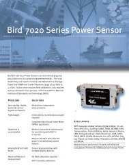
Remote Control, Logging Spectrum Monitor / Analyser2261A• Designed for Spectrum Data Logging withOn-Board GPS Receiver.• 38 Selectable 100MHz Wide-Bands.• -103dBm Sensitivity, Typical at 2MHz Bandwidth.• 5-6 Hours Continuous Battery Operating Time.2261AReceiverDataLoggingGPSGeneralFrequency Band 1 (1 x 100MHz Band)Frequency Band 2 (1 x 100MHz Band)Frequency Band 3 (15 x 100MHz Bands)Frequency Band 4 (21 x 100MHz Bands)BandwidthSensitivityOverload PointDamage LevelFrequency StabilityGraphic DisplayGraphic Resolution – PowerGraphic Resolution – FrequencyGraphic Dynamic RangeNumeric Dynamic RangeUpdate TimeMarkerTCP Markers (Optional)Marker ResolutionData RecordedMax. No. of RecordsRecord TimeFrequencyPosition AccuracyTiming AccuracyPosition Fix UpdateTime to LockReaquisition TimePowerDimensionsWeight890 ~ 940MHz (500kHz Resolution)2400 ~ 2500GHz (1MHz Resolution)3400 ~ 4200GHz (1MHz Resolution)4900 ~ 6000GHz (1MHz Resolution)2MHz-103dBm, Typical-30dBm, Typical+10dBm2 x 10 -5 (0°C ~ 50°C)64 x 128 Pixel, LCD1.25dB/Pixel1MHz/Pixel35dBm ~ -102.9dBm, Graphically Displayed24.1dBm ~ -103.8dBm, Numerically Displayed300ms (2ms Measure, 1ms Compute per Channel x 100 Channels)Marker Set with a Front Panel Knob. Marker Frequency & PowerIntercept are Displayed at the Top of the LCDDual Markers, Separated by User Setting (Knob), Capture & CalculateTotal Channel Power Between Markers. Markers Moved AcrossDisplay with Knob. TCP & Centre Freq. Shown on Display.0.3dB (Power), 1MHz FrequencyReceived Signal Level in dBm per Channel (Peak Hold & Average),Frequency, Longitude, Latitude, Date, Time, M/N & S/N of Instrument.255 Single Frequency or Band Sweep RecordsBand Sweep ≤2 Seconds, Single Frequency = 20ms, to Store Resultsin MemoryL1 (1575.42MHz), C/A Code (SPS), 8-Channel Continous Tracking,32 Correlators2 Meters CEP (50%)±95ns1sCold Start:
Vector Network AnalyserLA-19-13-01• 3MHz ~ 3GHz Range.• 100Hz Resolution.• 80dB Dynamic Range.• Time Domain Facility.• P1dB Measurements.• AM-PM Measurements.• Light Weight & Small Footprint.• Low Cost.LA-19-13-01MeasuringFunctionsMeasuring ParametersError CorrectionDisplay ChannelsTracesDisplay FormatsMemory TraceLimit LinesMarkersMarker FunctionsS11, S21S22, S12 (Manual Reverse of DUT)P 1dB (Power at 1dB Gain Compression)AM-PM Converstion FactorS11 (1 Port Correction)S21 (Normalise, Normalise + Isolation)S21 (Source Match Correction + Normalise + Isolation)Averaging, SmoothingHanning and Kaiser Bessel Filtering on Time Domain MeasurementsElectrical Length Compensation (Manual)Electrical Length Compensation (Auto)4 Channels (CH1, CH2, CH3, CH4)2 Traces / ChannelAmplitude (Logarithmic & Linear)Phase, Group Delay, VSWR, Real, Imaginary,Smith Chart, Time Domain1 Per Channel4 Segments4 MarkersNormal, Δ Marker, Fixed MarkerSignalSourceCharacteristicsFrequency RangeFrequency Setting ResolutionFrequency AccuarcyFrequency Temperature StabilityHarmonicsNon-Harmonic SpuriousPhase Noise (10kHz)Output PowerPower Setting ResolutionOutput Power Accuracy3MHz ~ 3.08GHz100Hz±10ppm (23 ± 3°C)±0.5ppm/° (15 ~ 35°C)-20dBc-35dBc-65dBc/Hz (3MHz ~ 800MHz)-73dBc/Hz (800MHz ~ 1600MHz)-68dBc/Hz (>1600MHz)0 ~ -20dBm1dB (Nominal)±1.5dB40Tel: +44 (0)20 8868 1311 Fax: +44 (0)20 8866 65961-3 Kildare Close, Eastcote, Ruislip, Middlesex HA4 9UR
LA-19-13-01ReceiverCharacteristicsResolution BandwidthAveraged Displayed Noise FloorDynamic RangeTemperature StabilityTrace Noise3kHz-80dBm (-90dBm Typical)80dB0.02dB/°C (Typical, after S21 Calibration)0.002dBrms (S21 Calibration, 3MHz ~ 3GHz, 401 Points,128 Averages)DataHandlingCalibration Data1Calibration Kit DataPrint Measurement Data (Graphics)Measurement Data & GraphicsMeasurement Data(Touchstone ® Format)Touchstone® is a trademark of AgilentStore / Recall on Hard Disk / Floppy DiskSotre / Recall on Hard Disk / Floppy DiskTo Any Installed Printer on Host PCStore on Hard Disk / Floppy DiskStore on Hard Disk / Floppy DiskRecall to Memory Trace from Hard Disk / FloppySweepFunctionsSweep TypeSweep SpeedNumber of PointsLinear Frequency Sweep, Power Sweep (P 1dB Utility)3ms / Point51, 101, 201, 401, 801, 1024TestPortCharacteristicsLoad MatchSource Match (Uncorrected)Directivity (Corrected)Crosstalk (Uncorrected)Maximum Input LevelConnectors24dB (30dB Typical)22dB (28dB Typical)40dB Min.65dB Min. (80dB Typical)+6dBm+23dBmType N (Female)GeneralControlling PC Data InterfaceExternal DimensionsWeightTemperature Range - OperatingTemperature Range - StorageHumidityPower SourcePower ConsumptionFusesRS-232, CTS/RTS Handshake, 115.2kb/s(or USB with Optional Adaptor)316mm x 140mm x 319mm5.8kg5°C ~ 35°C-10°C ~ 60°C80% Max. (Non-Condensing)AC 90 ~ 250V30VA Max.2 x 20mm, F1.6A, Quick Blow, IEC127www.aspen-electronics.com sales@aspen-electronics.comFOR EQUIPMENT CALIBRATION DETAILS, CALL OUR SERVICE DEPARTMENT TODAY… 41
Site AnalysersSA EX Range• Four Models Available.• One Model Covers 25 ~ 6000MHz.• Easy to Operate & Field Ready.• Suitable for Feeder & Antenna Testersin Worldwide, Cellular &PCS/DCS systems.• Optional RF Power Sensors, Thruline ®& Terminating.• Other Applications Include 3G, Broadcast, Government, Tactical Military, Microwave, Paging,Public Safety, Trunking, WLAN, and WLL, and TETRA - see Matrix Table Below.• Colour Display is Clearly Visible in Direct Sunlight.• With a Single Download you can View Data as Distance to Fault or Measurement Match.• Frequency Domain Reflectometry (FDR) Measurement Method Results in a Highly ReliableAssessment of the Health of Critical Components in your System.• Fault Location/DTF Mode Indicates VSWR or Return Loss Levels at Each Point Along the Cableand Antenna System Length.• Cable Loss Function Measures Insertion Loss of the Cable System over a given FrequencyRange.SA-6000EXSA-2500EXSA-1700EXPSA-1700EXFrequency RangeFrequency ResolutionPower MeasurementReturn LossTest PortImpedanceSpeedTrace ResolutionStorage CapacityImmunity to Interfering SignalsMaximum Input SignalData TransferInternal TimeExternal DCExternal ACOperating TemperatureStorage TemperatureHumidityAltitudeDimensionsWeightUpgradeable27 ~ 1700MHz25kHz;25 ~ 800MHz50kHz;800 ~ 1700MHz25 ~ 1700MHz25kHz;25 ~ 800MHz50kHz;800 ~ 1700MHz780 ~ 2500MHz50kHz25 ~ 6000MHz25kHz;25 ~ 800MHz50kHz;800 ~ 2500MHz150kHz;2500 ~ 6000MHzNoYesYesYes0 ~ -60dBN-Type Female501 Multi-Frequency Scan (238 Points)/2 Seconds1 Multi-Frequency Scan (475 Points)/3.5 Seconds1 Multi-Frequency Scan (949 Points)/6 Seconds238 (Default), 475 or 949 per trace15 Set-Ups/(500) 238 point tracesRejects on-frequency signals up to +13dBm+22dBm9-pin RS-232 (DB9), compatible with serial portRechargeable lithium-ion batteries. 3 hour maximum operating time.Auto shut-off conserves battery life.9-16 VDC fused,
Antenna TestersAT-Series• Battery Powered for Portable Operation Anywhere.• Measures: VSWR, Return Loss, Match Efficiencyor Reflection Coefficient.• EIA-232 Port Interfaces to a PC with OptionalCable and Software.• Up to 12 Measurements can be Stored inNon-Volatile Memory.The Bird AT-Series Antenna Testers provide a cost-effective, fast, graphical way of determining thequality of mobile and base station antennas. The unit can display single frequency or sweptreadings scaled in either VSWR, return loss or match efficiency and can save up to 12 traces forcomparison or later archiving with an optional cable and PC software package.AT-800AT-400AT-100Frequency Range2 ~ 136MHz65 ~ 520MHz806 ~ 960MHzFrequency Resolution20kHz30kHz30kHzFrequency Accuracy±50kHz±100kHz±100kHzMeasurement RangeVSWR: 1.00 ~ 99.99, Match Efficiency: 00 ~ 100.0%, Return Loss: 0.00 ~ 32.0dBMeasurement Speed; TypicalSingle Frequency: 5 Readings/Second, Sweep Frequency: 1 Sweep/SecondPre-Programmed BandsN/AN/AAMPS, NADC, GSM,PDC, CT2Field Strength0 ~ 100% (Relative) Sensitivity for Full-Scale Deflection:8 v/m @ 100MHz0.22v/m @ 400MHz3m @ 12.6 W ERPTest PortImpedance: 50Ω, Nominal. Connector (Others Available)N (F)TNC (F)InterfaceSerial (Female DB-9 Connector)Power RequirementsBatteries: 6 Rechargeable AA (KR-15/51)External DC: 11 ~ 16 VDC, External AC Adaptor: 108 ~ 132 VAC @ 57 ~ 63Hz,or 207 ~ 253 VAC @ 48 ~ 52HzOperating Temperature0°C ~ 50°CStorage Temperature-41°C ~ 71°CDimensions205mm x 118mm x 42 mmWeight0.8kgwww.aspen-electronics.com sales@aspen-electronics.comMANY PRODUCTS AVAILABLE TO BUY ONLINE, SEE OUR WEB-STORE: www.aspen-electronics.com/shop.html43
Microwave Antenna Alignment Test Set2200 / 2240 Path Align-R TM• Designed for Alignment of Microwave LinkAntennas Without the Need for Link Transceivers.• Tunable Bands from 1.8 ~ 23.5GHz.• Reduces Time to Complete Installation.• Continuous Talk & Listen Over Link Via IncludedHeadsets.• Path Loss Display Updated Every 300ms.22402200TransmitterTransmissionTransmitter Output PowerTransmitter StabilityTunable Frequency BandsFull-Duplex0dBm, Nominal5.1 x 10E -9 /day (aging) + 1 x 10E -6 (temp 0°C ~ 50°C)Model Numbers Ending in A Must Be Ordered With AtLeast One Frequency OptionOption 01 – Band 1 (Res. 1.0MHz)Option 02 – Band 2 (Res. 1.0MHz)Option 03 – Band 3 (Res. 1.0MHz)Option 04 – Band 4 (Res. 1.0MHz)1.8 ~ 2.5GHz5.8 ~ 6.6GHz11.0 ~ 12.0GHz18.1 ~ 19.4GHz1.8 ~ 2.5GHz3.5 ~ 5.0GHz& 5.8 ~ 6.6GHz7.4 ~ 10.0GHz& 11.0 ~ 12.0GHz18.1 ~ 19.4GHz& 22.0 ~ 23.5GHzReceiverGeneralDeviationTransmit / Receive OffsetModulationModulation Input / OutputReceiver SensitivityReceiver BandwidthReceiver Overload PointReceiver ReadoutExternal ReadoutVariable Alignment ToneInternal Speaker OutputEarpiece OutputSpeaker/Earpiece ControlPowerDimensionsWeight50 ~ 100kHz39MHzFM VoiceHandset W/10-foot Coiled Cord, Terminated in a 3.5mmPlug (Mic. & Earpiece)-100dBm Nominal (1.8 ~ 2.5GHz); -95dBm Nominal(3.5 ~ 6.6GHz); -90dBm Nominal (7.5 ~ 12.0GHz); -90dBmNominal (18.1 ~ 23.5GHz)100kHz, Nominal-30dBm (Damage Level: +10dBm)LCD Direct Path Loss in dB (Equivalent to Signal InputLevel in dBm), 0.1dB Resolution, Updated Every 300msExternal Readout of Path Loss with DVM (0 ~ 2 VDC),BNC Connector, Rear Panel600Hz ~ 6kHz, Varies with Signal Strength, SwitchSelectable350mW Max., Variable, Behind Front Panel250mW Max., Variable, 3.5mm Front Panel JackVariableSelf Contained 12V, 2.3Ah Rechargeable SealedLead-Acid Battery89mm (H) x 213mm (W) x 333mm (D)3.2kgORDERING INFORMATION22002200A22402240AOption 320Option 325Option 330Option 331Option 333Option 324Path Align-R with All Bands as Standard.Path Align-R where Desired Band must be Added.Extended Range Path Align-R with All Bands as Standard.Extended Range Path Align-R where Desired Band must be Added.Spare Battery.Adaptor – In-Line (SMA (F) to N (M).Adaptor – Waveguide to Coax N (F) CPR 137.Adaptor – Waveguide to Coax N (F) CPR 90.Adaptor – Waveguide to Coax SMA (F) CPR 42.Cable; Coax Cable Assembly SMA (M) ~ SMA (M).44Tel: +44 (0)20 8868 1311 Fax: +44 (0)20 8866 65961-3 Kildare Close, Eastcote, Ruislip, Middlesex HA4 9UR
Compact Spectrum Analyser7830• 100kHz ~ 2.9GHz.• Sweep Mode.• Peak Search Function.• Marker to Centre Function.AVAILABLETO BUY ONLINEProtek 7830FrequencyAmplitudeSweepMemoryDisplayInputFrequencyCounterGeneralOtherRangeResolutionAccuracyModulation BandwidthStep RangeSpan SelectionSpan RangeMeasurement RangeAverage Noise LevelAmplitude UnitsReference Level AccuracyReference Level RangesLog ScaleInternal AttenuationSpeedTrigger SourceTrigger ModeTrigger LevelMarker ModesTrace StorageSetup StorageTypeDisplay ResolutionLCD BacklightRF Input ConnectorMaximum Input PowerRangeRF Input ConnectorOperating TemperatureHumidityPower SourcePower AdapterSizeWeightSpeakerAntennaRS-232 Interface100kHz ~ 2900MHz3.125kHz (Multiples of 3.125kHz)TCXO: ± 3ppmWide FM: 180kHz (-6dB)Narrow FM: 12.5kHzAM / SSB: 2.4kHz (-6dB)AM / SSB: 2.5kHz; FM: 6.25kHzStart, Stop, Centre Span SetupMaximum Span is Dependent upon SelectedModulation Type-20dBm ~ -110dBmWide FM: -100dBmNarrow FM / AM / SSB: -110dBmdBm, dBmV, dBµVTypical 1.5dB (@ 20°C ~ 25°C)+20dBm ~ -90dBm0.2dB/Div min. in 0.25dB StepsMax 35dB (in 1dB steps)500msec ~ 2000msecNarrow FM / Wide FM / AM / SSBFree Run / Single Run / Continuous / Squelch RunTTL LevelMarker / Δ Marker / Peak Search /Marker to Centre / Channel Power100 Waveforms100 StatesMono LCD192 x 192 PixelsON / OFF / AUTON Type Female, 50ΩMax +10dBm, 5V RMS10MHz ~ 2900MHzBNC Type Female, 50Ω0°C ~ 40°C35% ~ 85% RHAA Type Ni-MH Rechargeable Battery x 6pcs12V DC Mains Adapter12V Car Adapter102mm (W) x 229mm (H) x 45mm (D) (excluding antenna)700g0.5W into 8Ω SpeakerDipole Antenna (Receive Only)9600 bps, 19200 bps, 38400 bps, 57600 bpsand 115200 bps8-pin MINI-DIN ConnectorStandard AccessoriesORDERING INFORMATIONAntenna, Batteries, Coaxial Cable, RS-232 Cable, Carrying Case, Carrying Strap, Headphone,Manual, PC Application Software.www.aspen-electronics.com sales@aspen-electronics.comIF YOU HAVE A REQUIREMENT THAT IS NOT SHOWN IN THIS CATALOGUE, PLEASE CONTACT US… 45
RF Field Strength Analysers3290Protek 3290N & 3201N• Wide Band Reception.• Handheld Unit.• Built In Frequency Counter & Speaker.3201AVAILABLETO BUY ONLINE3290N3201NFrequencyRange100kHz ~ 2900MHz100kHz ~ 2000MHzAmplitudeSweepMemoryDisplayInputResolutionAccuracyModulation BandwidthStep RangeFrequency SelectionMeasurement RangeAverage Noise LevelAmplitude UnitsReference Level AccuracyReference Level RangeLog ScaleInternal AttenuationSpeedTrigger SourceTrigger ModeTrigger LevelMarker ModesSweep ModesTrace StorageSetup StorageTypeDisplay ResolutionLCD BacklightRF Input ConnectorMaximum Input Power3.125kHz (Multiple of 3.125kHz)TCXO: ±3PPM, Display: ±1.5PPMWide FM: Approx. 180kHzNarrow FM: Approx. 12.5kHzAM / SSB: Approx 2.4kHzAM/SSB: 2.5kHz & FM: Multiple of 6.25Start, Stop, Centre Span Setup-20dBm ~ -100dBm-100dBmdBm, dBmV, dBµV±2.0dB±20dBm ~ -70dBm10dB10dB500 ~ 2000msecNarrow FM / Wide FM / AM / SSBFree Run / Single Run / Cont. Wave / Squelch RunTTL LevelMarker / Delta MarkerSpectrum, MultibarUp to 100 WaveformsUp to 100 StatesMono STN LCD192 x 192 PixelsON / OFFN Type Female, 50ΩMax +10dBm, 5VRMSFrequency CounterRange9MHz ~ 2900MHz9MHz ~ 2000MHzOther SpecificationsPowerGeneralOtherResolutionSample TimeRF Input ConnectorOperation TemperatureHumidityStorage TemperaturePower SourcePower AdaptorAuto PowerSizeWeightSpeakerAntennaRS-232C Interface7 Digits1secBNC Type Female, 50Ω (Standard)0°C ~ 40°C35%RH ~ 85%RH-10°C ~ 50°CAA Type Ni-MH Rechargeable Battery x 6pcsAC Adaptor, 12V DCCar Adaptor, 12V DCOff / 5min / 10min / 20min / 30min102mm (W) x 229mm (H) x 45mm (D)700g0.5W into 8Ω SpeakerDipole Antenna (Receive Only)9600bps, 19200bps, 38400bps,57600bps & 115200bps8-pin MINI-DIN Connector46Tel: +44 (0)20 8868 1311 Fax: +44 (0)20 8866 65961-3 Kildare Close, Eastcote, Ruislip, Middlesex HA4 9UR
TV Level MeterMM-0090T• Handheld Level Meter for Digital & AnalogueTV Channels.• Compact & Lightweight.• Measures Channel Power, Carrier/Noise Ratiofor all Channels.• RS-232 Interface.MM-0090TTuningRangeResolutionChannel Standards5 ~ 900MHz125kHzDK, BG, MN(AIR), MN(CATV)Level MeasurementAmplitude RangeAccuracyResolutionBandwidthDetectorAttenuatorAdditional Measurements30dBµV ~ 126dBµV±1.5dB (18°C ~ 28°C)±2.2dB (-10°C ~ 40°C)0.1dB230 ± 60kHzPeak Value0, 20, 40dB (Automatic)C/N (Carrier/Noise), V/A (Video/Audio)Voltage MeasurementRange10V ~ 100V DC or RMSPowerBattery TypeBattery LifeCharging TimeNIMH AA x 6≥6 Hours14 Hours Approx.GeneralDisplayOperation TemperatureDimensionsWeight57 x 40mm, 128 x 64 Pixels-10°C ~ 40°C90mm (W) x 200mm (H) x 55mm (D)600g (Including Battery)Standard AccessoriesBatteries, RS-232 Cable, Carrying Case, Manual,PC-Software, Mains Adapter.Interchangeable Modules• Handheld Platform AllowingAlternative Plug-in Modules.• Modules to Include:Satellite TV Level Meter,TDR & Optical Power Meter.www.aspen-electronics.com sales@aspen-electronics.comOUR RANGE IS CONSTANTLY EXPANDING, SEE OUR WEBSITE FOR NEW PRODUCT DETAILS… 47
Timer, Counter AnalyserCNT-90• Unique Ease-Of-Use Multi-ParameterDisplay, with Statistical & GraphicalPresentation of Results.• 14 Digits Display.• USB & GPIB Interfaces Standard.• Frequency Range: 300MHz Standard.3, 8, 14 & 20GHz Optional.CNT-90MeasuringInput Range A, BFunctionsInput Range C (Optional)Frequency ResolutionA, B & C Aux. Parameters0.001Hz ~ 300MHzUp to 3, 8, 14 or 20GHz12 digits in 1s Measuring TimeVmax, Vmin, Vp-pFrequencyBurst A, B, CFunctionsInput Range A, B, CMinimum Burst DurationMinimum Pulses In BurstPRF RangeStart DelayAux. ParametersFrequency in Burst (in Hz), PRF (in Hz), Number of Cycles in BurstSee Frequency Spec.40ns (CH A & B)Input A or B: 3 (6 above 160MHz), Input C: 3 x prescaler factor0.5Hz ~ 1MHz10ns ~ 2s, 10ns ResolutionPRF, Number of Cycles in BurstPeriod A, B,C AverageInput Range A & BInput Range C (optional)ResolutionAux. Parameters3.3ns ~ 1000sDown to 330, 125, 70 or 50ps100ps (single shot); 12 digits/s (average)Vmax, Vmin, Vp-pRatio A/B, B/A,C/A, C/BRangeInput Frequency A, BInput Frequency C (optional)Aux. Parameters10 -9 ~ 10 110.1Hz ~ 300MHzUp to 3, 8, 14 or 20GHzFreq 1, Freq 2Time IntervalA to B, B to A,A to A, B to BNormal Calculation RangeSmart Calculation RangeResolutionMin. Pulse WidthSmart Calculation-5ns ~ +10 6 s-10 6 s ~ +10 6 s100ps1.6nsSmart Time Interval to Determine Sign (A before B or A after B)Positive &Negative PulseWidth A, BRangeMin. Pulse WidthAux. Parameters1.6ns ~ 10 6 s1.6nsVmax.Vmin, Vp-pRise & Fall TimeA & BRangeTrigger LevelsMin. Pulse WidthAux. Parameters700ps to 1000s10% & 90% of signal amplitude1.6nsSlew rate, Vmax, VminPhase A Relative RangeB, B Relative A ResolutionFrequency RangeAux. Parameters-180° ~ +360°0.001° up to 10kHz, decreasing to 1° at >10MHzResolution can be improved via averaging (statistics mode)Up to 160MHzFreq (A), Va/Vb (in dB)48Tel: +44 (0)20 8868 1311 Fax: +44 (0)20 8866 65961-3 Kildare Close, Eastcote, Ruislip, Middlesex HA4 9UR
CNT-90Positive &Negative DutyFactor A, BRangeFrequency RangeAux. Parameters0.000001 ~ 0.9999990.1Hz ~ 300MHzPeriod, pulse widthVmax, Vmin,Vp-p A, BRangeFrequency RangeModeResolutionUncertainty (5V Range)Aux Parameters-50V ~ +50V, -5V ~ +5VRange is limited by the spec. for max input voltage without damageDC, 1Hz ~ 300MHzVmax, Vmin, Vp-p2.5mVDC, 1Hz ~ 1kHz: 1% +15mV; 1kHz ~ 20MHz: 3% + 15mV;20 ~ 100MHz: 10% + 15mV; 100 ~ 300MHz: 30% + 15mVVmin, Vmax, Vp-pTime Stamping FunctionA, B Maximum Sample SpeedMaximum FrequencyResolutionInput & OutputSpecificationsInputs A & BFrequency RangeImpedanceTrigger SlopeSensitivityAttenuationDynamic Range (x 1)Trigger LevelResolutionAuto Trigger LevelAnalogue Low Pass FilterDigital Low Pass FilterMax. Voltage without DamageConnectorRaw time stamp data with pulse counts accessible via GPIB or USBSee GPIB specification160MHz100psDC ~ 300MHz (10Hz, AC Coupled)1MΩ//20pF or 50ΩPositive or NegativeDC ~ 200MHz: 15mVrms; 200 ~ 300MHz: 25mVrmsx 1, x 1030mVp-p ~ 10Vp-p within a ±5V windowDisplayed on the screen2.5mVSet to 50% points of input signal (10% and 90% for rise & fall time)Nominal 100kHz1Hz ~ 50MHz cut off frequency1MΩ: 350V (DC + AC peak) up to 440Hz, falling to 12Vrms at 1MHz50Ω: 12VrmsBNCInput C(Option 10)Input Voltage RangePrescaler FactorProtection VoltageConnector100 ~ 300MHz: 20mVrms ~ 12Vrms0.3 ~ 2.5GHz: 10mVrms ~ 12Vrms2.5 ~ 2.7GHz: 20mVrms ~ 12Vrms2.7 ~ 3GHz: 40mVrms ~ 12Vrms1612Vrms, pin-diode protectedType-N FemaleInput C(Option 13)Input Voltage RangePrescaler FactorProtection VoltageConnector200 ~ 500MHz: 20mVrms ~ 7Vrms0.5 ~ 3GHz: 10mVrms ~ 7Vrms3 ~ 4.5GHz: 20mVrms ~ 7Vrms4.5 ~ 6GHz: 40mVrms ~ 7Vrms6 ~ 8GHz: 80mVrms ~ 7Vrms2567Vrms, pin-diode protectedType-N FemaleInput CFrequency Range(Option14 & 14B) Input RangePrescaler FactorAM ToleranceProtection LevelConnector0.2 ~ 14GHz (Option 14)0.2 ~ 20GHz (Option 14B)200 ~ 400MHz: -21 ~ +27dBm1 ~ 14GHz: -27 ~ +27dBm14 ~ 18GHz: -27 ~ + 27dBm (Option 14B only)18 ~ 20GHz: -21 ~ +27dBm (Option 14B only)128>90% within sensitivity range+27dBm, pin-diode protectedPrecision N Femalewww.aspen-electronics.com sales@aspen-electronics.comFOR PRICE & AVAILABILITY, CALL US NOW… 49
CNT-90Rear PanelConnectionsAuxiliaryFunctionsExternal Start& Stop ArmingReference InputReference OutputArming InputRear Panel InputModesInput ChannelsMaximum Repetition RateStart Time Delay Range1, 5 or 10MHz; 0.1 ~ 5Vrms10MHz; >1Vrms sine into 50ΩArms all measurement functionsOptional A, B, C input on rearStart, Stop & Start & Stop armingA, B or EChannel A, B: 160MHzChannel E: 80MHz20ns ~ 2s, 10ns resolutionTrigger Hold-offTime Delay Range20ns ~ 2s, 10ns resolutionStatisticsFunctionsDisplaySample SizeMeasurement PacingMinimum, Maximum, Mean, Delta, Max-Min,Standard Deviation & Allan DeviationNumeric, Histograms or Trend Plots2 ~ 2 x 10 9 samplesTime range: 2ms ~ 1000sMathematicsFunctions(K*X+L)/M & (K/X+L)/M.Where X is reading and K, L and M are user definable constantsOther FunctionsMeasuring TimeTime Base ReferenceDisplay HoldLimit ValuesLimit AlarmDisplaySetup MemoryDisplay DigitsResolutionGPIB InterfaceInternal Memory SizeUSB Interface20ns ~ 1000s for frequency, burst and period averageSingle cycle for other measurement functionsInternal, External or AutomaticFreezes result until a new measurement is initiated via restart buttonLower and upper limitsGraphical indication on display and / all SRQ via GPIBNumeric & graphics20 memories for instrument setup14 digits in numerical mode320 x 97 pixelsCompatibility: IEEE 488.2 compatible. 53131A emulation modeMaximum measurement rate via GPIB: 2k readings/sMaximum measurement rate to internal memory: 250k readings/s750k readingUSB 2.0, up to 11Mb/sPhysicalPower RequirementsDimensionsWeightBasic Version: 90 ~ 265Vrms, 45 ~ 440Hz,
Microwave Timer, Counter, AnalyserCNT-90XL• Unique Ease-Of-Use Multi-Parameter Display,with Statistical & Graphical Presentation of Results.• 27, 40, 46 & 60GHz Models.• 14 Digit Display.• USB & GPIB Interfaces Standard.• CW & Burst Measurements of Frequency & Power.Measuring Input Range A, BFunctions Input Range CFrequency ResolutionA, B & C Acquisition (Input C only)Acquisition TimeAux. Parameters Input A & BAux Parameters Input CPeriod A, B, Input Range A & B(Single or Input Range CAverage), C Resolution(Average) Acquisition (Input C only)Acquisition TimeAux. ParametersRatio A/B, B/A, RangeC/A, C/B Input Frequency A, BInput Frequency CAux. ParametersPower C Power RangeFrequency RangeResolutionAccuracyAcquisitionAcquisition TimeAux. ParametersInputFrequency Range DC CoupledSpecifications Frequency Range AC CoupledInputs A & B SensitivityAttenuationDynamic Range x1Analogue Noise Red. FilterDigital Low Pass FilterImpedanceMax Voltage Without DamageInput CConnectorFrequency RangeOperating Input RangeImpedanceVSWRFM ToleranceAM ToleranceAuto Amplitude DiscriminationMax Voltage Without DamageConnectorCNT-90XL0.001Hz ~ 300MHz300MHz ~ 27, 40, 46 or 60GHz12 digits in 1s measuring timeAuto or Manual (within ±40MHz)25ms in Auto (typ.)Vmax, Vmin, Vp-pPower in dBm3.3ns ~ 1000s4ns down to 37, 25, 22 or 17ps100ps (Single); 12 digit/s (Average)Auto or Manual (Within ±40MHz)25ms in Auto (typ.)Power in dBm10 -9 ~ 10 110.1Hz ~ 300MHz300MHz Up to 27, 40, 46 or 60GHzFreq 1, Freq 2-35dBm ~ +10dBm300MHz Up to 27, 40, 46 or 60GHz0.01dBm @ 100ms Measuring Time300MHz ~ 27GHz:
CNT-90XLAuxiliaryFunctionsExternal Start& Stop ArmingStatisticsMathematicsOther FunctionsModesInput ChannelsStart Time Delay RangeFunctionsDisplaySample SizeLimit QualifierFunctionsMeasuring TimeTimebase ReferenceDisplay HoldStored Instrument Set-UpsDisplayArming Can Be Used To Synchronise Frequency & PowerMeasurements with the Start of a Burst Signal.Minimum Burst Length Must Exceed 10μSStart & Stop ArmingA, B or E (Ext. Arming Input)20ns ~ 2s, 10ns ResolutionMax, Min, Mean, ΔMax-Min, Standard Deviation & Allan DeviationNumeric, Histograms or Trend Plots2 ~ 2 x 10 9 SamplesOFF or Capture Values Above/Below/Inside or Outside Limits(K*X+L)/M & (K/X+L)/M. X Is Current Reading & K, L & Mare Constants20ns ~ 1000sInternal, External or AutomaticFreezes Result, Until a New Measurement Is Initiated Via Restart20Backlit Graphics LCD; 320*97 PixelsInterfacesGeneralSpecificationsEnvironmentalDataGeneralMax. Measuring SpeedClassOperating TemperatureStorage TemperatureHumidityAltitudeVibrationShockTransit Drop TestSafetyEMCMains PowerSizeWeightTo PC: 40/s (Individual), 5000/s (Block)Up to 250k/s (Up to 750k Stored Results)MIL-PRF-28800F, Class 30°C ~ 50°C-40°C ~ +71°C5% ~ 95% (10°C ~ 30°C)5% ~ 75% (30°C ~ 40°C)5% ~ 45% (40°C ~ 50°C)4600mRandom & Sinusoidal According to MIL-PRF-28800F, Class 3Half-Sine 30G per MIL-PRF-28800F Bench HandlingAccording to MIL-PRF-28800FEN 61010-1, Pollution Degree 2, Meas Cat I,CSA C22.2 No 1010-1, CE90 ~ 265Vrms, 45 ~ 440Hz,
Timer, Frequency Counter, CalibratorsCNT-81, Timer Counter & CNT-85, Counter• CNT 81: 11 Digits Per Second Resolution.• Choice of Rubidium or OCXO Reference.• 8GHz Input Option.CNT-85CNT-81MeasuringModesFrequency A, B, CFrequency BurstPeriod AFrequency RatioTime Interval A-BPulse Width AV-Max, V-MinV P-P, A, BInputs A & BAnalogue Low Pass Filter, ADigital Low Pass FilterInput CFrequency RangeOption 20 CNT-81 Input Voltage RangeOption 10 CNT-85Input COption 13Input AInput BInput C (option)ResolutionInput AInput BInput CRangeResolutionRangeRangeResolutionRangeResolutionRangeRise & Fall Time APhase A Relative B RangeResolutionDuty Factor A RangeTotalise A, B RangeModesRangeFrequency RangeSpec. ResolutionCouplingImpedanceMax. Ch. Timing Diff.Max. SensitivityAttenuationManual TriggerAuto TriggerImpedanceVoltage Protection LevelConnectorInput Voltage RangeImpedanceConnectorUp to 300MHzUp to 100MHz100MHz ~ 2.7GHz (Option 20)300MHz ~ 8GHz (Option 13)11digit/s1ms1ms50ms3.3ns ~ 10 10 s11 digit/sA/B, C/B: 10 -9 ~ 10 150ns ~ 10 10 s50ps (1ps average)3ns ~ 10 10 s50ps (1ps average)3ns ~ 10 10 s-180° ~ +360°0.01°0.000001 ~ 1.0000000 ~ 10 17 ,0 ~ 10 10 in A-B ModesA Gated by BA Start/Stop by BManual Gating A minus BTimed Gating A minus B-50 ~ +50VUp to 100MHz1.25mVAC or DC1MΩ//15pF & 50Ω500ps20mVrms,
CNT-85CNT-81Rear PanelInputs & OutputsReference InputReference OutputArm InputAnalogue OutputGate OutputProbe Compensation Output1, 2, 5 or 10MHz; >200mVrms10MHz; >0.5Vrms into 50Ω LoadArms most measurement functions0 ~ 4.98V in 20mV steps;proportional to 3 selecteddisplay digitsGate Open/Gate Closed SignalOutput to adjust for best responsewhen using probes10MHz; >200mVrms10MHz; >0.5Vrms into 50Ω LoadArms most measurement functions0 ~ 4.98V in 20mV steps;proportional to 3 selecteddisplay digits (included withGPIB Option)N/AN/AGPIB (Option 80on CNT-85)Maximum MeasurementRate via GPIBMeas. Rate to Internal MemoryInternal Memory Size250 readings/s8k readings/s6100 readings100 readings/s1.6k readings/s2600 readingsCNT-81 AUXILIARY FUNCTIONSTimeView – Modulation Domain Analysis Software.Maths Functions.Statistics.Trigger Hold-off.External Arm/Gate.Battery Option.Frequency Offset.External Arm/Gate.Storage of >20 Setups.10 Digit LCD Display.CNT-85 AUXILIARY FUNCTIONSCOMMON AUXILIARY FUNCTIONSCNT-81CNT-81ROption 13Option 20Option 27Option 27HOption 30Option 40CNT-81 ORDERING INFORMATIONTimer Counter, 300MHz/50ps.Timer Counter Calibrator, 300MHz/50ps, Including Rubidium Timebase.8GHz Input C.2.7GHz Input C.Soft Carrying Case.Heavy Duty Hard Transport Case.Very High Stability Oven Time Base (1 x 10 -8 /month).Ultra High Stability Oven Time Base (5 x 10 -9 /month).CNT-85 ORDERING INFORMATIONCNT-85CNT-85ROption 10Option 13Option 23/85Option 27Option 27HOption 30Option 40Option 80Frequency Counter, 300MHz.Frequency Counter/Calibrator, 300MHz, Including Rubidium Timebase.3GHz Input C.8GHz Input C.Battery Pack.Soft Carrying Case.Heavy Duty Hard Transport Case.Very High Stability Oven Time Base (1 x 10 -8 /month).Ultra High Stability Oven Time Base (5 x 10 -9 /month).GPIB Interface.54Tel: +44 (0)20 8868 1311 Fax: +44 (0)20 8866 65961-3 Kildare Close, Eastcote, Ruislip, Middlesex HA4 9UR
Modulation Domain AnalysisTimeView Software• View Dynamic Frequency Changes Over Time.• Follow Frequency Changes Every 4µs in Real Time.• Applications Include: VCO Settling,PLL Response, Frequency Hopping,Chirp Radar, Frequency Droop & Frequency Loss.TimeView forCNT-81TimeView forCNT-90HW & SW RequirementsMeasurement FunctionsSpeedTransfer SpeedResult MemoryTimestamp ResolutionCapture ModesRepetitive SamplingWaveform MeasurementsZero Dead TimeTimestampingDisplay ModesAnalysis ModesOperating SystemPC InterfacesFrequencyPeriodTime IntervalPhaseDuty FactorFrequency RatioVoltage Max/Min/P-PPulse WidthRise/Fall TimeTime StampingTotaliseSample Speed To Internal MemoryTo PC(result plus timestamps)Free Running Measurements(Requires Repetitive Signal)Statistical DistributionStatistical numerical AnalysisDual Cursor ReadoutFFT AnalysisSmoothingTimestamp Data AnalysisUSB, GPIBYYYYYYYYYYUp to 250000 samples/s10000 samples/s375k results70 ps rms
GPS Controlled Frequency StandardGPS-12R• GPS-disciplined Rubidium clock forNear-Cesium Stability.• 2.048MHz, 1-pps standard outputs forTelecom Applications.• 1.544MHz (T1) Optional.• 5 & 10MHz Optional Low-NoiseOutputs for General Lab Use.• Battery & -48Vdc OptionsGPS-12RFrequency Stability(Locked to GPS)Allan Deviation (20°C~ 26°C)Phase NoiseWarm Up (+25°C)
High Stability Frequency Standards6688 & 6689• Rubidium or High Stability Oven FrequencyReference Standard.• Distribution Amplifiers for 5 x 10MHz & 1 x 5MHzOutputs as Standard.• Optional 10 x 10MHz Outputs.• 0.001ppm Aging in 10 Years (Rubidium).• Ideal for Telecommunication Test Systems &Calibration Laboratories.6688Oven6689RubdiumOutputOutput TypeLevelSinewave>0.6Vrms into 50ΩFrequencyStabilityAging/MonthAging/10 Years; Aging/YearTemperature StabilityShort Term (Root Allan Variance)Warm Up (at 25°C)5x10 -111x10 -9 (10 years)3.5x10 -10= ح 1x10 -11 10s=ح 3x10 -11 1s5.4 min. to lock11 min. to 4x10 -103x10 -92x10 -8 (1 year)2.5x10 -9= ح 5x10 -12 10s=ح 5x10 -12 1s10 min. to 5x10 -9Environmental Temperature - OperatingTemperature - StorageSafetyEMI0°C ~ +50°C (Operating)-40°C ~ +70°C (Storage)Compliant to EN 61010-1, Cat II, Pollution Degree 2, CECompliant to EN 55011 ISM Group, Class B & EN 50082-2, CEPower Consumption
Fibre Optic & Coax Distribution AmplifiersDA-35 & DA-36• Low Loss, Enabling Very Long Lengths.• Minimal Degradation of Carrier-to-Noise.• Lightweight, Highly Flexible, Small Diameter Cable.• Immunity to Electrical Interference.DA 35 &DA 36CommonSpecificationsElectrical InputSignalElectrical OutputSignalsConnectorBandwidthImpedanceAmplitudeConnectorAmplitudeBNC200kHz ~ 16MHz sine50Ω200mVrms ~ 2Vrms (sine)BNC1VrmsOptical FibreCharacteristicsFibre TypeConnector TypePeriod-Period JitterMax. Recommended LengthMultimode FibreST< (50ps + Optical Jitter)2kmFibre Optic Distribution Systems - DescriptionA customised solution for the distribution of a reference clock can be configured to suit individualrequirements. The system can be built up from a combination of self contained DA-36 units, or themore flexible, modular DA-35 system.The distribution is completely analogue over fibre and the signal is reconstructed with the help of asteep bandpass filter. Interference, such as noise and distortion, can be completely eliminated bythe filter.The signal to noise ratio in the received signal can be almost equal, and in certain cases, better thanthe input signal, even in cases where the signal is distributed hundreds of metres.By using a fibre optic cable for transmission, a galvanic isolation is created between the transmitterand receiver. The fibre is immune to external disturbances such as cross-talk and ESD.The receiver has automatic gain control, which makes installation and adjustments easier. Distancesup to 2000 metres can be achieved.DA 36 PHYSICAL CHARACTERISTICSUser InterfaceGeneralCo-ax Status LEDReceiver Status LEDDimensionsWeightGreen: a valid electrical input signal is present on the input.Red: input signal is lost / weakGreen: a valid optical signal is present on the inputRed: Received light level below threshold125mm x 170mm x 30mm1.1kgORDERING INFORMATIONDA-36 Fibre & Co-ax Distribution Amplifier. DA-35/10 Rack Holding 10 Cards.DA-35/02Mini Rack Holding 2 Cards.DA-35/21Card: 4 x BNC Inputs.DA-35/22Card: 4 x BNC Outputs.DA-3523Card: Optical In, 4 x BNC Outputs.DA-35/24Card: 4 x Optical Output.58Tel: +44 (0)20 8868 1311 Fax: +44 (0)20 8866 65961-3 Kildare Close, Eastcote, Ruislip, Middlesex HA4 9UR
Universal CounterFC300• Wide Frequency Range.• High Resolution, 9 Digits/s (10 Digits).• Period & Peak Voltage Measurements.• Save & Recall Function.AVAILABLETO BUY ONLINEChannel 1Channel 2Frequency Range10Hz ~ 220MHz100MHz ~ 3GHzResolution9 Digits/sec9 Digits/secSensitivity100kHz ~ 100MHz :≥ -20dBm (22mVrms)100MHz ~ 220MHz :-13dBm (50mVrms)100MHz ~ 2GHz :≥ -32dBm2GHz ~ 3GHz :≥ -25dBmMax Input Level5Vrms MAX5Vrms MAXInput ConditioningImpedanceCouplingLPFAttenuator1MΩ or 50ΩAC or DC100kHz, Switchablex1 or x1050ΩACN/AN/ATrigger LevelAuto TriggerManual TriggerPeriod (µsec)Set Level by %of Signal LevelSet Level byAbsolute VoltagePeak Voltage(±5V Max, 0.01V Step)50%N/AN/AAnalysisAutomatic Limit TestingGate Time0.1sec, 0.5sec, 1sec, 10sec selectableTime BaseInternalExternalFrequency: 10MHzStability: Standard: ±0.5ppm TCXOFrequency: 10MHzInput Level: 0.2Vrms ~ 5Vrms @ impedance 1kΩInterfaceRS-232CGPIB (Option 1)Power115/230 VAC, 50/60HzGeneralDimensionsWeight100mm (H) x 210mm (W) x 350mm (D)3.6kgFC300Option 1Option 23GHz Universal CounterGPIB Interface.High Stability OCXO (±5 x 10 -8 ).ORDERING INFORMATIONwww.aspen-electronics.com sales@aspen-electronics.comOUR RANGE IS CONSTANTLY EXPANDING, SEE OUR WEBSITE FOR NEW PRODUCT DETAILS… 59
Universal CounterU2000A• 0.1Hz ~ 2GHz Frequency Range.• Measures: Frequency, Period, Totalise & Ratio.• Variable Trigger Level.• 8 Digit LED Display.AVAILABLETO BUY ONLINEU2000AFrequency RangeChannels A & BChannel CRange 1: 0.1Hz ~ 10MHzRange 2: 10MHz ~ 100MHz10MHz ~ 2GHzSensitivityChannels A & BChannel C0.1Hz ~ 100MHz: 25mVrms20MHz ~ 1.6GHz: 25mVrms10MHz ~ 2.0GHz: 50mVrmsInput CharacteristicImpedance Channels A & BImpedance Channel CMax. Input Voltage Channels A & BMax. Input Voltage Channel CResolution Channels A & BResolution Channel C1MΩ 30pF50Ω250V (DC + AC Peak)3VrmsRange 1: 0.1 / 1/ 10 / 100HzRange 2: 1 / 10 / 100 / 1000Hz10 / 100 / 1 / 10kHzTime BaseReference Oscillator Channels A & BReference Oscillator Channel CShort Term StabilityTemperature Stability10MHz3.90625MHzAging: ± 3 x 10 -7 / Month±5 x 10 -6 (0°C ~ 40°C)Gate TimeChannels A & BChannel C0.01s / 0.1s / 1s / 10s0.0256s / 0.256s / 2.56s / 25.6sRatio A/BRangeMultiplier10 ~ 100MHz1 / 10 / 10 / 1000 (4 Modes)PeriodRange5Hz ~ 2MHz, 0.01 / 0.1 / 1 / 10sTime Interval Range (A ~ B)5Hz ~ 2MHz, 1 / 10 / 100 / 1000 (4 Modes)TotaliseRangeDC ~ 10MHzGeneralPower RequirementsDimensionsWeight100 / 120 / 220 / 230VAC ± 10%, 50 / 60Hz253mm (W) x 280mm (D) x 95mm (H)2.4kg60Tel: +44 (0)20 8868 1311 Fax: +44 (0)20 8866 65961-3 Kildare Close, Eastcote, Ruislip, Middlesex HA4 9UR
RF Power MetersML2490A, ML2480A & ML2430A Series• Frequency up to 50GHz.• Dual Channel Display.• Advanced Trigger Facilities.• RS-232 & GPIB Interface as Standard,USB & LAN Options.SpecificationsSensor/ChannelControlGeneralML2496AML2488AML2438AFrequency RangePower SensorsSensor Dynamic RangePower Measurement RangeChannel BandwidthSample RateInstrument AccuracyDisplay ResolutionDisplay UnitsPower Reference LevelPower Reference ConnectorOperating ModesProfileMarkersGatesAveragingDisplaySave & RecallGPIBModelMA2472BMA2473AMA2474AMA2475AMA2421AMA2422BMA2423BMA2424BMA2425BMA2442BMA2444AMA2445AMA2458BMA2481BMA2482AMA2490AMA2491AMA2411APower Meter, Dual Input.Power Meter, Dual Input.Power Meter, Dual Input.ML2490A100kHz ~ 65GHz, Sensor DependentCompatible with all MA2400 Series of SensorsUp to 90dB Depending on Choice of Sensor-70 ~ +20dBm Depending on Sensor Range,External Coupler & Attenuator20MHz (>65MHz in 20MHz100kHz NominalRepetitive Mode)Up to 64MS/s Depending on Settings< 0.5%; ± 0.02dB (Absolute Accuracy), ± 0.04dB (Relative Accuracy)Selectable from 0.1 ~ 0.001dBLinear: nW ~ W, %; LOG, dBm, dBW, dB1mW, Nominal 50MHzType N Female, VSWR ≤ 1.04Pulse/Modulated forWidebandMeasurements plus CWAvg, Peak, Crest,Max/Min, PDF, CDF,CCDF & PAE4 Markers & 1 DeltaMarker, Marker toMax/Min, Pulse Rise/FallTime, Off Period &Pulse Repetition Interval4 Independently SetGates or 8 RepeatedGatesAveraging of Trace 1 ~512LCD Colour withVGA OutputConnector20 Sets of Memory>400 Readings/s inCWML2480ARead Out, Dual Displayof Channel RF PowerCDMA Average, PeakPower, Crest Factor,CDF, PDF & CCDF4 Markers; Delta Marker,Marker to Max/Min, PulseRise/Fall Time, OffPeriod & Pulse RepetitionInterval4 Independently SetGates or 8 RepeatedGatesAveraging of Trace 1 ~512LCD Colour20 Sets of Memory>400 Readings/s inCWSENSORS SUMMARYGeneral DescriptionStandard Diode, 18GHz, 90dB Dynamic Range.Standard Diode, 32GHz, 90dB Dynamic Range.Standard Diode, 40GHz, 90dB Dynamic Range.Standard Diode, 50GHz, 90dB Dynamic Range.Fast Thermal, 18GHz, 50dB Dynamic Range, Low Frequencies.Fast Thermal, 18GHz, 50dB Dynamic Range.Fast Thermal, 32GHz, 50dB Dynamic Range.Fast Thermal, 40GHz, 50dB Dynamic Range.Fast Thermal, 50GHz, 50dB Dynamic Range.High Accuracy Diode, 18GHz, 87dB Dynamic Range.High Accuracy Diode, 40GHz, 87dB Dynamic Range.High Accuracy Diode, 50GHz, 87dB Dynamic Range.Fast Diode (0.6μs Rise Time), 6GHz, 80dB Dynamic Range.Universal, 6GHz, 80dB Dynamic Range.Universal, 18GHz, 80dB Dynamic Range.Wideband, 8GHz, 80dB (18ns Rise Time) Dynamic Range.Wideband, 18GHz, 80dB (18ns Rise Time) Dynamic Range.Pulse (Sensor Rise Time 8ns), 40GHz, 40dB Dynamic Range.ORDERING INFORMATIONML2495A Power Meter, Single Input.ML2487A Power Meter, Single Input.ML2437A Power Meter, Single Input.ML2430ARead Out, Dual Channelof RF PowerPower v. Time of SingleChannel2 Manually AdjustableCursors-Averaging of Trace 1 ~512LCR Monochrome10 Sets of Memory>200 Readings/s inCWwww.aspen-electronics.com sales@aspen-electronics.comOUR RANGE IS CONSTANTLY EXPANDING, SEE OUR WEBSITE FOR NEW PRODUCT DETAILS… 61
High Accuracy Power Meter4421• Laboratory Grade precision Digital RF Power Meter.• +/-1% or +/-3% Accuracy Dependent on Sensor.• Wide Dynamic Range.• Excellent Measurement Repeatability - typically
RF Digital Power MeterModel 5000-EX RF Digital Power Meter• Hand-Held & Field Ready.• Easy-To-Use Digital Display.• Compatible with Digital & Analogue Signals.• Used with a Bird ® Power Sensor –DirectionalPower Sensor; 5010T, Terminating PowerSensor; 5011, and the new Bird ® WidebandPower Sensor; 5012The “NEW” Industry Standard Hand-Held RF Power Meter Easy-To-Operate & Field Ready.The Model 5000-EX must be coupled with Model 5010T Thruline Power Sensor, Model 5011Terminating Power Sensor or Model 5012 Wideband Power Sensor. Model 5000-EX handlesCellular, PCS, AMPS, CDMA, GSM, TDMA, ISM, UMTS, 3G Wireless, WLL, Paging,Conventional/Trunked Radio, Aviation, Military, and Analogue or Digital & Television Broadcast.Model 5000-EX is also compatible with pulse modulation systems, such as radar & avionicsapplications (TACAN, DME), where peak power measurements are required.5000-EXDisplayBack-lit Liquid Crystal, 57 x 76mm. Three-way Display Consisting of Major andMinor Digital Display Elements, Analogue Bar Graph Element, Annunciators,Battery Indicator and Speed-Key Legends.Measurement ModeDependent on SensorTrue Average Power, for Measurement of Conventional or Digitally-ModulatedRF Peak Power, for Pulse, SSB, AM & Avionics ApplicationsSensor Interface9-pin D-Shell RS-232 Serial Connector. Sensor is Powered from Meter.DPM-5000EX is Compatible with Bird VSWR Alarm Products & Broadcast PowerMonitor (BPM) Product FamilyPC Interface Dimensions9-Pin RS-232 Serial Port for Connection to a PCDimensions203mm (H) x 117.6mm (W) x 44.5mm (D)Weight0.68kgPower SupplyRechargeable Nickel-Metal Hydride (NiMH) BatteryMeter May Be Operated From AC Mains Using Supplied AdaptorBattery Life100 Hours Min. Per ChargeOperating Temperature-10°C ~ +50°CStorage Temperature-40°C ~ +75°CHumidity95% Max. (Non-Condensing)Standard AccessoriesInstruction Manual, Serial Communications Cable (Sensor), AC Charger/Adaptorwww.aspen-electronics.com sales@aspen-electronics.comFOR PRICE & AVAILABILITY, CALL US NOW… 63
Thruline ® Directional Power Sensor5010T• Measures True Average Power.• ±5% of Reading Accuracy Rivals Thermal Wattmetersin Actual Field Use.• Small, Easily-Remoted Sensor Facilitates ConvenientHand-Held Operation.• Dual-Element THRULINE ® Design for SimultaneousForward and Reflected Power Readings.• The 5010T Power Sensor is a Perfect Choice forTactical Communication and Avionics Systems whereHigh Performance Directional Power Measurementsare Required.• Can be used with <strong>Aspen</strong> <strong>Electronics</strong> VDPM Kit.The Model 5010T Dual-Socket THRULINE ® Power Sensor is a precision 50-ohm, 7/8 inch “Smart”Line Section which accepts Bird ® digital-ready Plug-in DPM Elements. The Model 5010T Sensorprovides true average power readings for digital as well as traditional analogue RF systems.The Model 5010T Power Sensor is compatible with many existing Bird ® accessories for 7/8” line,including signal samplers, and over 20 types of QC connectors. QC Connectors can rapidly andconveniently be changed in the field by removing four screws from the connector.5010T Element GuideSpecifications - 5010TForward ReflectedFrequency Power Power Forward ReflectedRange Range Range Element Element2-30MHz 1.25-50W 125mW-5W DPM-50H DPM-5H2-30MHz 12.5-500W 12.5-50W DPM-500H DPM-50H25-60MHz 1.25-50W 125mW-5W DPM-50A DPM-5A25-60MHz 12.5-500W 12.5-50W DPM-500A DPM-50A50-125MHz 1.25-50W 125mW-5W DPM-50B DPM-5B50-125MHz 12.5-500W 12.5-50W DPM-500B DPM-50B50-125MHz 25W-1kW 2.5-100W DPM-1000B DPM-100B100-250MHz 1.25-50W 125mW-5W DPM-50C DPM-5C100-250MHz 12.5-500W 1.25-50W DPM-500C DPM-50C100-250MHz 62.5W-2.5kW 6.25-250W DPM-2500C DPM-250C200-500MHz 125mW-5W 12.5-500mW DPM-5D DPM-.5D200-500MHz 1.25-50W 125mW-5W DPM-50D DPM-5D200-500MHz 12.5W-500W 1.25-50W DPM-500D DPM-50D400-960MHz 125mW-5W 12.5-500mW DPM-5E DPM-.5E400-960MHz 1.25-50W 125mW-5W DPM-50E DPM-5E400-960MHz 2.5-100W 250mW-10W DPM-100E DPM-10E400-960MHz 12.5-500W 1.25-50W DPM-500E DPM-50E400-960MHz 25W-1kW 2.5-100W DPM-1000E DPM-100E950-1260MHz 125mW-5W 12.5-500mW DPM-5J DPM-.5J950-1260MHz 1.25-50W 125mW-5W DPM-50J DPM-5J1100-1800MHz 125mW-5W 12.5-500mW DPM-5K DPM-.5K1100-1800MHz 1.25-50W 125mW-5W DPM-50K DPM-5K1700-1990MHz 125mW-5W 12.5-500mW DPM-5L1 DPM-.5L11700-1990MHz 1.25-50W 125mW-5W DPM-50L1 DPM-5L11700-1990MHz 12.5-500W 1.25-50W DPM-500L1 DPM-50L11990-2200MHz 1.25-50W 125mW-5W DPM-50L2 DPM-50H1900-2200MHz 125mW-5W 12.5-500mW DPM-5L2 DPM-500H2200-2300MHz 625mW-25W 62.5mW-2.5W DPM-25M DPM-5L22200-2300MHz 125mW-5W 12.5-500mW DPM-5M DPM-.5L22300-2500MHz 125mW-5W 12.5-500mW DPM-5N DPM-.5N2500-2700MHz 125mW-5W 12.5-500mW DPM-5R DPM-.5RSensor Type:Frequency &Power Range:Accuracy:Dynamic Range:Peak/Average:Setting Time:Connectors:Insertion VSWR:Dimensions:Weight:Operating Temp.:Storage Temp.:Humidity:Note:Bird ® THRULINE ® directionaldual-element line section.Dependent upon elements,Please view element guide forcurrent listing.125mW ~ 1000W*.±5% of reading (15° to 35°C),±7% of reading (-10° to 50°C).40:1 (e.g. 50W element measure1.25W to 50W).10dB maximum with DPMelements.
Wideband Power SensorModel 5012• Easy to use and competitively priced.• Wide Dynamic Range (350MHz ~ 4,000MHz).• Digital Power Meter Connection or Direct Connectionto PC or Site Analyser – No Black Box!• 30dB Directivity up to 3GHz; 28dB up to 4GHz.• Directional-Forward and Reflected Power.• No Elements Required.When combined with a Digital Power Meter, Site Analyser family of line and antenna analysisproducts or a Personal Computer, the Wideband Power Sensor becomes an integral part of a veryrobust and sophisticated power measurement solution.5012SensorCharacteristicsGeneralFrequency RangePower Measurement RangeImpedanceInsertion LossInsertion VSWRInput ConnectorOutput ConnectorDirectivity350MHz ~ 4GHz0.15W ~ 150W Average, 400W Peak50Ω (Nominal)
Terminating Power SensorModel 5011 & 5011EF• Significant Cost & Time Savings, Easy to Use& Field Ready.• Both Digital as well as Analogue ModulationsIncluding (CDMA, GSM, TDMA, 8-VSB & COFDM).• Broadcast Transmitter Power with Accuracy of±5% of Readings.• Measure Power Directly or Via Coupled Test Port.5011EF5011Sensor TypeTerminating Power Sensor, Terminated Average Power MeasurementFrequency Range40MHz ~ 4GHz40MHz ~ 12GHzPower Range-20 ~ +10dBm (10µW ~ 10mW)Peak/Average Ratio12dB MaximumAccuracy±5% of Reading ±1mW RSS (Excluding Mismatch Uncertainty)Warm Up Time5 MinutesInput Impedance50Ω NominalInput VSWRTypical 1.03 (36.6dB Return Loss);Maximum 1.20 (20.8dB Return Loss)Typical 1.05 (32.3dB Return Loss);Maximum 1.25 (19.1dB Return Loss)Input ConnectorPrecision N MaleOutput ConnectorMale DB-9 to Interface to Digital Power Meter or Site AnalyserPower SupplyFrom Host Instrument Via Cable ConnectionOperating Temperature-10°C ~ 50°CStorage Temperature-40°C ~ 80°CHumidity95% Maximum (Non Condensing)AltitudeUp to 15,000 FeetSize6” Long (Including Connectors); 1.5” DiameterWeight340g66Tel: +44 (0)20 8868 1311 Fax: +44 (0)20 8866 65961-3 Kildare Close, Eastcote, Ruislip, Middlesex HA4 9UR
Remote Digital Power Meter SoftwareModel ASP-5010T-Remote• Read data directly from 5010T Thruline ®Power Sensor (powered via hardware interface).• Simultaneously display parameters of ForwardPower, Reflected Power, VSWR and Return Loss.• Allow any one of these parameters to beincreased in size for a primary ‘view’.• Full windowed display can be increased to maximised window size.• Each of the four parameters can have set limits, and if out of limit numerical display is changedto ‘red’.• Below each power indicator is an analogue bar indicating value relative to full scale for adjustmentpurposes.• Logging capability - around four readings per second of all parameters, saved as a filename.txt file.• Settings allow com ports to be specified, & rated power of the forward and reflected elements tobe entered.Note: Forward power is shown above in'primary view' - larger display.Note: VSWR display in primary view shows thereading (in red) exceeds the set limit.The Bird ® <strong>Electronics</strong> RF Thruline Power Sensor Model 5010T is normally supplied with dual DPMelements and a Digital Power Meter DPM 5000-EX is required to read and display the measuredparameters.As many engineers now use a PC and / or carry a Laptop PC to set radio parameters,<strong>Aspen</strong> <strong>Electronics</strong> has developed VDPM software and a hardware data interface to read anddisplay the parameters of the sensor directly on a PC via the RS-232/USB adaptor, thuseliminating the need for Digital Power Meter DPM-5000EX.Part No: ASP-5010T-REM Inclusive of Hardware interface, software on disc, RS-232 cable andRS-232/USB adaptor.Bird ® <strong>Electronics</strong> 5010T and elements are sold separately.www.aspen-electronics.com sales@aspen-electronics.comFOR EQUIPMENT CALIBRATION DETAILS, CALL OUR SERVICE DEPARTMENT TODAY… 67
USB Power SensorMA24106A• Economic Alternative to Traditional Benchtop Meters.• True RMS Measurements Over a 63dB Dynamic Range.• 50MHz ~ 6GHz.• High Damage Power Levels & ESD Protection.• No Need for a Reference Calibrator.• Lightweight & Easy to Use.MA24106ASensorFrequency RangeDynamic RangeInput Return LossMeasurement RangesSignal Channel Bandwidth50MHz ~ 6GHz-40dBm ~ 23dBm>26dB (50MHz ~ 20dB, (2GHz ~ 6GHz)Range 1, -40dBm ~ -5dBm; Range 2, -5dBm ~ 23dBm100Hz TypicalMeasurementUncertaintyLinearityCalibration FactorNoiseZero SetZero DriftTemperature Compensation (0 ~ 50°C)Effect of Modulation±0.13dB (Power Level
Thruline ® RF Directional WattmetersModels 43, 43P, 4304A & 4410A• Accurate CW Field Power Measurement.• Uses Industry Standard Bird Elements with Spaceto Store 2 Additional Within the Meter Housing.• Rugged Metal Housing for the Most DemandingEnvironmentsPower RangeFrequency RangeInsertin VSWRAccuracyConnectorsSize & WeightElements43 Portable Wattmeter100mW ~ 10kW Using Bird ® Plug In Elements450kHz ~ 2.7GHz (Depending on Element)With N Connectors 1.05 Max ~ 1000MHz±5% of Full ScaleQC Type (Female N Normally Supplied)175 (H) x 130 (W) x 92 (D) mm 1.4kgTables 1, 2, 3, 3A, 4, & 643P Peak Power Retrofit Kit 4300 ~ 400 Portable WattmeterPower RangeFrequency RangeAccuracyModulationBattery LifeWeight100mW ~ 10kW Using Bird ® Plug In Elements450kHz ~ 2.7GHz (Depending on Element)CW Mode: ±5% of Full Scale, Peak Mode: ±8% Full ScaleNormal Voice Audio; or (Peak Mode) Rectangular Pulses. Duty Cycle: 2% (Min),Repetition Rate: 100pps (Min). Pulse Width: 200μs (Min)48 Hours Typical1.75kg4304A 25 ~ 1000MHz 5 ~ 500W ElementPortable Wattmeter with Fixed ElementPower RangeFrequency RangeInsertion VSWRInsertion LossAccuracyConnectorsSize & Weight5, 15, 50, 150, 500W With No Scale Limitations,Except Power Limited to 150W from 800 ~ 1000MHz25MHz ~ 1GHz25 ~ 521MHz, 1.05 Max. (With UHF Female Conn.) 512 ~ 1000MHz, 1.07 Max.25 ~ 512MHz, 0.10dB Max. with UHF Female Conn.,512 ~ 1000MHz Range, 0.13dB Max.25 ~ 100MHz, ±7% of Full Scale, Using Connection Charts.100 ~ 512MHz, ±6% of Full Scale, No Correction Needed.512 ~ 1000MHz, ±7% of Full Scale , No Correction Needed.QC Type (Female N Normally Supplied)175mm (H) x 130mm (W) x 92mm (D) Including Connectors 1.36kg4410A Multipower ±5% Reading Accuracy Portable WattmeterPower RangeFrequency RangeInsertion VSWRAccuracyAmbient Temperature RangeOver RangeConnectorsSize & Weight2mW ~ 10W 20mW ~ 100W 200mW ~ 1kW or 2W ~ 10kW Full Scale in OneSingle Plug In Element. Any Bird Series 4410-Element May Be Used.200kHz ~ 2.3GHz CW or FMWith N Connectors 1.25 Max. to 2300MHz±5% of Reading for Any Reading Above 20% of the Power Range Selected for FM or CWSignals without AM. This Accuracy is Maintained for a Full 37dB Dynamic Range withEach 4410 Element (Except 4410-15 1.0 ~ 1.8GHz & 4410-16 1.8 ~ 2.3GHz Which AreAccurate to ±8% of Reading.Elements 4410-1 Through -8 and -10 Through -16 are temperature Compensated ForRated Accuracy From 0°C ~ 50°C and 4410-20 Through -27 from 20°C ~ 30°CTo 120% of Nominal Full Scale (i.e. 12W, 120W, 1200W, or 12,000W). No Damage orDegredation to the Unit Will Result, Regardless of the Range Selector Switch Position.QC Type (Female N Normally Supplied)175mm (H) x 130mm (W) x 92mm (D) 4410A: 1.4kg 4412: 1.5kgwww.aspen-electronics.com sales@aspen-electronics.comMANY PRODUCTS AVAILABLE TO BUY ONLINE, SEE OUR WEB-STORE: www.aspen-electronics.com/shop.html69
Antenna MonitorACM Range• Compatible with Analogue or Digital Cellularand Two-Way Radio Systems.• Worldwide Applications Include Tetra, Cellular,PCS and many others.• Monitors VSWR and Power Level and ProvidesAlarm Outputs.• Sensitive to Antenna Faults that InternalTransmitter VSWR Monitors Might Not Detect.• Local or remote operation via PC.• Ideal for multi-carrier applications.ACM-HACM-MACM-LForward PowerVSWR AlarmCharacteristicsPhysical &EnvironmentalFrequency RangeReflected Power DirectivityMeasurement RangePower AccuracyInsertion LossVSWRAlarm Set PointRelay Contact TypeContact RatingVisual AlarmStimulusResetMonitor PortsInterface Port- Connectors- Coupling- Connector-ProtocolGeneralRF ConnectorsMaximum Line Section PowerAlarm/Power ConnectorOperating TemperatureStorage TemperatureHumidityAltitudePassive Intermodulation:--Products- Power Req.- DimensionsWeight136 ~ 510MHz 520 ~ 960MHz 960 ~ 2400MHz2.5 ~ 100W, contact us to enquire about other powermeasurement ranges±5% of reading, ±1 count0.1dB, 136 ~ 960MHz0.15dB, 960 ~ 2400MHz1.07, 136 ~ 960MHz1.1, 960 ~ 2400MHz30dB, 136 ~ 960MHz26dB, 960 ~ 2400MHz1.3, 1.4, 1.5, 1.6, 1.7, 1.8 to 1Dry, Form C, relay contacts.Common, normally open, normally closed100VDC @ 0.5ARed LED will illuminate to indicate alarmVSWR set point exceeded, response time proportional to overloadLocal mechanical reset switchRemote input (reset if VDC is 0 ~ +0.8V)N Female or TNC Female60dB approx.Subject to changes in full-scale powerFemale DB-9, compatible with IBM PC AT serial portSerial RS-232, 9600 baud, no parity, 8 data bits, 1 stop bit,no handshakeThruline sensor for direct insertion in 50Ω lineN or 7-16 DINDependent on frequency and connector15-pin male “D” connector0°C ~ 50°C-20°C ~ 80°C0 to 95% maximum (non-condensing)Up to 3000 meters above sea level
Programmable AC Power SuppliesSmartwave Series• Ideally Suited for Aerospace Test Applications.• Powerful Waveshape & Waveform Creation.• Sequence Programming.• Models up to 21kVA Total Power.• Graphic LCD Display.• Powerful DSP2 Waveform Programming.SW-5250SW-3500SW-1750OutputWaveformSpecificationsMeasurementBoard (Optional)Power Factor of LoadAC or DC Output VoltageOutput Current, Single PhaseCrest FactorOutput Frequency RangeOutput PowerMax. Total Harmonic Distortion(Full Linear Load or No Load)AC Noise LevelAmplitude Stability(with Remote Sense)Load RegulationLine Regulation(DC, or 40Hz ~ 5kHz)Voltage AccuracyVoltage ResolutionFrequency ResolutionFrequency AccuracyPhase Accuracy, (Phase-to-PhaseBalanced Linear Resistive Load)Phase Angle ResolutionRemote Output Voltage SenseWaveshape LibrariesFront Panel SetupsSequencing LibraryLibraries IncludedMeasurements IncludedMeasurement CapabilityCalibration Interval0 Lagging to 0 Leading0 ~ 156 Vrms L-N Range 1: 0 ~ 312 Vrms L-N Range 2156V Range:13A (up to 135V);312V Range:6.5A (up to 270V)4.0 (Peak Output Current to RMS Output Current)DC or 2Hz ~ 6kHz (Over 1kHz, Max Slew Rate is 1kHz/s)1750VA, Single Ø156V Range:26A (up to 135V);312V Range:13A (up to 270V)1750VA/Ø, Dual Ø3500VA, Single Ø156V Range:39A (up to 135V);312V Range:19.5A (up to 270V)1750VA/Ø, Three Ø5250VA, Single Ø0.25% Max., 40 ~ 100Hz; 0.5% Max., 100 ~ 500Hz;1% Max., 500Hz ~ 1kHz; 1% per kHz, 1kHz ~ 5kHz>60dB RMS Below Fall Output Voltage±0.1% of Full Scale Over 24 Hours at Constant Line,Load and Temperature0.025% of Full Scale Voltage for a Full Resistive Load to No Load;up to 1kHz±0.025% of Full Scale for a ±10% Input Line Change±0.1% of Range. Above 1kHz, add 0.2% per kHz.Add 0.1% of Full Scale for “AC + DC” Mode.0.05% of full scale40Hz ~ 99.99Hz: 0.01Hz100Hz ~ 999.9Hz: 0.05Hz1000Hz ~ 5000Hz: 0.05Hz0.01% at 25°C, ±0.001% per °C±1°, 40Hz ~ 1kHz, ±1° per kHz above 1kHz0.1%5V RMS total lead drop, Max.50 Factory Supplied in ROM; Storage Available for up to 50 UserCreated Waveforms in Non-Volatile RAMA Total of 50 User Created Steady State Waveforms withAmplitude, Frequency, Phase Angle and Current Limit Parameters1000 User Created Segments Stored in Non-Volatile RAMSegments Include: Waveshape, Amplitude, Frequency, PhaseAngle, Time and Number of CyclesMIL-STD-704 Transient LibraryPhase to Neutral RMS Output VoltagesPhase to Phase Voltages1Ø to 3Ø RMS Output CurrentPeak CurrentOutput Frequency1Ø to 3Ø Power1Ø to 3Ø VAPower Factor of 1Ø to 3Ø LoadsOutput Phase Angles Relative to Phase A4.5 Digit Analogue to Digital Measurement System with 0.01%of Full Scale Resolution12 Monthswww.aspen-electronics.com sales@aspen-electronics.comIF YOU HAVE A REQUIREMENT THAT IS NOT SHOWN IN THIS CATALOGUE, PLEASE CONTACT US… 71
SW-5250SW-3500SW-1750InputProtection &SafetyGeneralInput Voltage RangesInput Power FactorInput Frequency RangeEfficiencyRide ThroughOver-Voltage ShutdownProg. Current Limit ShutdownProg. Current Limit withtimed ShutdownProg. Constant CurrentOver Temperature ShutdownCoolingSizeFactory Configured 187 ~ 264Vrms, 3Ø L-L (3 Wire) or342 ~ 457Vrms, 3Ø L-L (4 wire). A Chassis Ground is alsoRequired. 115 or 230 Vac Single Phase is Required for PDUin 10.5 ~ 21kVA Systems0.6; or 0.35 for International Rectifier. 0.99 with PFC Option.43 ~ 63Hz>70% at full load3ms Minimum. 10ms Minimum with PFC Option.Programmable for 20V ~ 255V Peak in 156V Range,40V ~ 510V Peak in 312V Range.Settable to 1% of RangeSettable to 1% of Range, Timeout Settable from 10ms ~ 10sSettable to 1% of Range. For all Current Accuracies add±1.5%/kHz above 500Hz. For Paralleled Amplifiers add ±1%Automatic, Non-ProgrammableAir Drawn in Through Top, Bottom and Sides and isExhausted Through Rear222mm (H) x 483mm (W) x 597mm (D)Weight33.1kg45.4kg57.5kgOther StandardFeaturesOptionsFlexibilityRemote ControlWaveform Trigger OutputBNC OutputsSync. OutExternal AMExternal DriveSingle Phase to Three Phase Independently ProgrammableGPIB, IEEE-488-2 Interface, SCPI1MΩ Load DriveFor Viewing Waveforms on Oscilloscope, 1MΩ Load DriveUser Programmed for Cycle: Cycle Start, all Cycles.Segment Start, all or Selected Segments.0 ~ 5Vrms Provides 0 ~ ≥20% Output AMNormal Amplifier 0 ~ 5Vrms (DC ~ 5kHz) or ±5Vdc input for0 to full Voltage Output• Measurement Board.• Input Power Factor Correction to 0.99.• Parallelable for Additional Power from 10.5kVA to 21kVA.• External Waveform Creation Software: Allows Arbitrary WaveformControl of Each Phase Independently.ModelNumberSW 1750A-1SW 1750A-2SW 1750A-3SW 1750A-4SW 3500A-1SW 3500A-2SW 3500A-3SW 3500A-4SW 5250A-1SW 5250A-2SW 5250A-3SW 5250A-4ORDERING INFORMATIONOutputACPower RatingInput1750 VA187 ~ 264 Vrms (L-L), 3-Wire1750 VA342 ~ 457 Vrms (L-L), 4-Wire1750 VA187 ~ 264 Vrms (L-L), 3-Wire1750 VA342 ~ 457 Vrms (L-L), 4-Wire3500 VA187 ~ 264 Vrms (L-L), 3-Wire3500 VA342 ~ 457 Vrms (L-L), 4-Wire3500 VA187 ~ 264 Vrms (L-L), 3-Wire3500 VA342 ~ 457 Vrms (L-L), 4-Wire5250 VA187 ~ 264 Vrms (L-L), 3-Wire5250 VA342 ~ 457 Vrms (L-L), 4-Wire5250 VA187 ~ 264 Vrms (L-L), 3-Wire5250 VA342 ~ 457 Vrms (L-L), 4-WirePower FactorCorrectionNoNoYesYesNoNoYesYesNoNoYesYesModelNumberPARALLEL CONFIGURATIONS FOR HIGHER POWERSOutputPower Rating5250 Master/Slave ConfigurationSW 10500 10.5kVA1 Master SW 5250 & 1 Slave 5250.SW 1575015.75kVA1 Master SW 5250 & 2 Slave 5250.SW 2100021.00kVA1 Master SW 5250 & 3 Slave 5250.72Tel: +44 (0)20 8868 1311 Fax: +44 (0)20 8866 65961-3 Kildare Close, Eastcote, Ruislip, Middlesex HA4 9UR
Programmable AC Power SuppliesCW Series• Manual & Programmable Versions.• 500Hz Standard, Optional 1kHz Output.• Power up to 2500VA.CW-2501CW-1251CW-801OutputPowerPower OutputPower Factor of LoadPhase800VA1250VA0 Lag to 0 LeadSingle Phase Output2500VAVoltageRangesAccuracy - ManualAccuracy - ProgrammableResolutionTotal Harmonic Distortion0 ~ 135Vrms or 0 ~ 270Vrms - user Selectable±1% of Range±0.1% of Range 100Hz0.1Vrms0.25% Typical
CW-2501CW-1251CW-801Frequency RangeAccuracy - ManualAccuracy - ProgrammableResolution of DisplayPower *RangeAccuracyResolutionApparent Power * RangeAccuracyResolutionPower Factor * Range(Programmable AccuracyVersion Only) ResolutionCrest Factor * Range(Programmable AccuracyVersion Only) ResolutionPhase Angle(ProgrammableVersion Only)Front PanelIndicatorsInputGeneralRangeAccuracyResolutionMenu/Status - ManualMenu/Status - Prog.Voltage - ManualVoltage - Prog.Current/Frequency - ManualCurrent/Frequency - Prog.Program/Measure - Prog. onlyV Range High/Low - Prog. OnlyVoltage & FrequencyCurrentPower FactorEfficiencyRegulatory ComplianceDimensionsWeight45 ~ 500Hz (45 ~ 1000Hz Optional on Programmable Unit Only)±0.5% of Reading±0.02% of Value0.1Hz0 ~ 800W0 ~ 1250W0 ~ 2500W±2% of Range for Linear Loads1W0 ~ 800VA0 ~ 1250VA0 ~ 2500VA±2% of Range for Linear Loads1VA0 ~ 1±4% of Range for Linear Loads0.010 ~ 3.5±5% of Range0.01-359° ~ +359° Positive Phase Indicates Time Lag from ReferenceWithin 100 Microseconds of Equivalent Angle1°Green LED for SlaveRed LED for FaultGreen LEDs for RemoteIndicators for Fault & LockoutEnter/Escape Buttons Present for ProgrammingGreen LED (Volts), displayGreen LED (V, W, VA, PF, OVP), DisplayGreen LED (A), DisplayGreen LED (A, Hz, Pk A, CF, I Limit), DisplayGreen LEDGreen LED90 ~ 264 Vac,47 ~ 63Hz,Single-Phase13 Arms Max.89mm (2U) (H) x 483mm (W)x 524mm (D)22kg103 ~ 264 Vac,47 ~ 63Hz,Single-Phase18.5 Arms Max.> 0.99 Typical at Full Load Nominal Line> 73% Typical at Full LoadCE Mark, UL & CUL24kg180 ~ 264 Vac,47 ~ 63Hz,Single Phase19.5 Arms Max.233 (3U) (H) x 483(W) x 524 (D) mm39kgNOTE *: In a parallel system (Programmable units only), Current/Power displayed on the master is the sum of all units in the system.ORDERING INFORMATIONOutput (Single Phase)Input (Single Phase)Model NumberMaximum Power Max Current 135V Max Current 270V Voltage (47 ~ 63Hz)CW-801M (Manual) 800VA 6.0A3.0A90 ~ 264 VacCW-1251M (Manual)1250VA9.4A4.7A103 ~ 264 VacCW-2501M (Manual)2500VA18.6A9.3A180 ~ 264 VacCW-801P (Programmable)800VA6.0A3.0A90 ~ 264 VacCW-1251P (Programmable)1250VA9.4A4.7A103 ~ 264 VacCW-2501P (Programmable)2500VA18.6A9.3A180 ~ 264 VacOption H Expanded Frequency Range 45 ~ 1000Hz (CW-P Only).Option L Locking Shafts (Front Panel Potentiometers) (CW-M Only).Option S Sync In/Out (Clock/Lock) (Standard on CW-P).K161570-01 Rack Slide Kit.890-497-40 Multi-Unit Cable.890-499-00 Digital Expansion Cable - Required to Parallel or Configure a 3Ø System (CW-P Only).74Tel: +44 (0)20 8868 1311 Fax: +44 (0)20 8866 65961-3 Kildare Close, Eastcote, Ruislip, Middlesex HA4 9UR
Programmable DC Power SuppliesSG Series, 5kW ~ 150kW (in 5kW Modules)• High Power Density, up to 15kW in 3U or 30kW in 6U.• Intelligent Sequencing Control on SGI.• Parallelable up to 150kW.• Optional 16-bit LAN, GPIB & RS-232 Interfaces.• Five Year Warranty.POWER & CURRENT COMBINATIONSVOLTAGE5kW10kW15kW20kW25kW30kWRMSRippleP-PNoise40V125A250A375A500A625A750A20mV75mV60V83A167A250A333A417A500A20mV75mV80V62A125A188A250A313A375A20mV100mV100V50A100A150A200A250A300A20mV100mV160V31A63A94A125A156A188A25mV150mV200V25A50A75A100A125A150A25mV175mV250V20A40A60A80A100A120A30mV200mV330V150A30A45A61A76A91A30mV200mV400V12A25A38A50A63A75A30mV200mV600V8A17A25A33A42A50A75mV350mVOutputInputRipple & NoiseSlew RateLine RegulationLoad RegulationTransient ResponseEfficiencyStabilityTemperature CoefficientOutput Float VoltageVoltageFrequencyPower FactorProtectionCOMMON SPECIFICATIONSVoltage Mode: See Table AboveCurrent Mode: 0.9 typical at 208/220Vac Input>0.78 typical at 380/400 Vac InputHalf Cycle Ride-through on all Three Phases, Three CycleRide-through on Single Phase; Missing Phase Shut-downwww.aspen-electronics.com sales@aspen-electronics.comFOR PRICE & AVAILABILITY, CALL US NOW… 75
COMMON SPECIFICATIONSCommonRemote Analogue ProgrammingProgramming AccuracyRemote Analogue MonitoringOver Voltage ProtectionDigital ProgrammingDigital Programming &Readback ResolutionModulationAdditional Output PowerDimensionsWeightVoltage, Current (0 ~ 100%) and OVP (5 ~ 110%) can beProgrammed by Selectable 0 ~ 5V, 0 ~ 10V or 0 ~ 5kΩVoltage: ±0.25% of Full Scale OutputCurrent: ±0.8% of Full Scale OutputVoltage & Current can be Monitored with 0 ~ 10V OutputsCorresponding to 0 ~ 100%Programming Range: 5 ~ 100% Settable from Front Panel,Remote Analogue or via Optional Digital InputsSGI: RS-232 - Standard, GPIB/Ethernet - OptionalSGA: RS-232 & GPIB/Ethernet - OptionalVoltage: ± 0.1% of Full Scale OutputCurrent: ± 0.4% of Full Scale Output± 0.002% of Full Scale OutputAnalogue Input is Summed with the Digital Programming Signal toAllow Modulation of the Output Voltage and Current SettingsUp to 5 units May be Paralleled for Additional Current.Paralleling Cable Required.5 ~ 15kW Units: 133.4mm (H) x 483mm (W) x 635mm (D)20 ~ 30kW Units: 266.7mm (H) x 483mm (W) x 635mm (D)5 ~ 15kW Units: 36kg, 20 ~ 30kW Units: 73kgSGA/SGI COMPARISON CHARTModular DesignFast Load TransientParallelableAnalogue & Digital SummingDirect Front Panel V/I Control3½ Digit LED ReadoutGraphics DisplaySequencingSave/Recall SetupsSystem Power ReadoutsConstant Power ModeIEEE-488.2/RS-232CEthernet/RS-232CSGAYYYOptionalYYN/AN/AN/AN/AN/AOptionalOptionalSGIYYYYYYYYYYRS-232C StandardIEEE.488.2 OptionalRS-232C StandardEthernet OptionalORDERING INFORMATIONSG ModelOption AOption IOption COption DOption EOption 1AOption 1COption 1DOption 1EOption 2AOption 2GSelect Model from the Previous Table with Desired Voltage & Current Output.Analogue Control.Intelligent Control.187 ~ 242Vac, Three Phase.342 ~ 440Vac, Three Phase (Standard).396 ~ 528Vac, Three Phase.GPIB & RS-232 (RS-232 Standard with SGI).Ethernet & RS-232 (RS-232 Standard with SGI).Isolated Analogue Programming Control of V/I/OVP and ISOLATED V/I Monitor Outputs.Shaft Locks (SGA only).Combine both Options 1A & 1D.Combine both Options 1C & 1D.76Tel: +44 (0)20 8868 1311 Fax: +44 (0)20 8866 65961-3 Kildare Close, Eastcote, Ruislip, Middlesex HA4 9UR
Programmable DC Power SuppliesP63 Series, 3.3kW, 6.6kW & 10kWP66 Series, 13kW, 16.5kW & 20kW• Low Peak-to-Peak Ripple & Noise.• Optional GPIB & RS-232 InterfaceModel P63 Series *Model P66 Series *OutputDC AmpsOutputDC VoltsModel P66 Series *13.3kW ~ 20kWOutputDC AmpsOutputDC VoltsModel P63 Series *3kW ~ 10kWP63D-55000 ~ 5500P66D-520000 ~ 52000P63D-510000 ~ 51000P66D-525000 ~ 52500P63D-515000 ~ 51500P66D-530000 ~ 53000P63D-84000 ~ 8400P66D-916000 ~ 81600P63D-88000 ~ 8800P66D-820000 ~ 82000P63D-812000 ~ 81200P66D-824000 ~ 82400P63D-103300 ~ 10330P66D-1013000 ~ 101300P63D-106600 ~ 10660P66D-1016500 ~ 101650P63D-1010000 ~ 101000P66D-1020000 ~ 102000P63D-12.52650 ~ 12.5265P66D-12.510600 ~ 12.51060P63D-12.55300 ~ 12.5530P66D-12.513250 ~ 12.51325P63D-12.58000 ~ 12.5800P66D-12.516000 ~ 12.51600P63D-152000 ~ 15220P66D-158800 ~ 15880P63D-154000 ~ 15440P66D-1511000 ~ 151100P63D-156000 ~ 15660P66D-1513200 ~ 151320P63D-201660 ~ 20166P66D-206650 ~ 20665P63D-203300 ~ 20330P66D-208300 ~ 20830P63D-205000 ~ 20500P66D-2010000 ~ 201000P63D-251340 ~ 25132P66D-255200 ~ 25520P63D-252650 ~ 25265P66D-256500 ~ 25650P63D-254000 ~ 25400P66D-258000 ~ 25800P63D-301100 ~ 30110P66D-304400 ~ 30440P63D-302200 ~ 30220P66D-305500 ~ 30550P63D-303300 ~ 30330P66D-306600 ~ 30660P63D-40830 ~ 4083P66D-403300 ~ 40330P63D-401660 ~ 40166P66D-404150 ~ 40415P63D-402500 ~ 40250P66D-405000 ~ 40500P63D-50660 ~ 5066P66D-502650 ~ 50265P63D-501330 ~ 50133P66D-503300 ~ 50330P63D-502000 ~ 50200P66D-504000 ~ 50400P Series ModelOption ROption AB* NOTE: For Models of 60V & Above, See SG-SeriesFor more detailed specification, please request full Sorensen catalogue.ORDERING INFORMATIONSelect Model from Above Table with Desired Voltage & Current Output.Replace P with R for Remote Control Option.Add AB to Model Number for Isolated Analogue Interface.www.aspen-electronics.com sales@aspen-electronics.comCALL US NOW TO ARRANGE A DEMONSTRATION & EVALUATION… 77
Programmable DC Power SuppliesDLM Series, 3kW & 4kW• High Power Density, 3 & 4kW in 2U High, 19” Wide.• Remote Voltage Sense.• Optional GPIB & RS-232 Interfaces.• Five Year Warranty.Current(Adc)Voltage(Vdc)3kW Models DLM 5-350EDLM 8-350EDLM 16-185EDLM 32-95EDLM 40-75EDLM 60-50EDLM 80-37EDLM 150-20EDLM 300-10EDLM 600-5E4kW Models DLM 5-450EDLM 8-450EDLM 16-250EDLM 32-125EDLM 40-100EDLM 60-66EDLM 80-50EDLM 150-26EDLM 300-13EDLM 600-6.6E0 ~ 50 ~ 80 ~ 160 ~ 320 ~ 400 ~ 600 ~ 800 ~ 1500 ~ 3000 ~ 6000 ~ 50 ~ 80 ~ 160 ~ 320 ~ 400 ~ 600 ~ 800 ~ 1500 ~ 3000 ~ 6000 ~ 3500 ~ 3500 ~ 1850 ~ 950 ~ 750 ~ 500 ~ 370 ~ 200 ~ 100 ~ 50 ~ 4500 ~ 4500 ~ 1500 ~ 1250 ~ 1000 ~ 660 ~ 500 ~ 260 ~ 130 ~ 6.6Rear PanelControl &MonitoringRemote SenseRemote Sense ProtectionRemote Analogue ProgrammingMaster SlaveSoftwareDimensionsWeightMaximum Drop 2V on 5V, 8V & 16V Models.5V for all Other ModelsUnit has Protection Against Damage Caused by Mis-connectionof the Remote Sense LeadVoltage, Current (0 ~ 100%) and OVP (5 ~ 110%) of Full Scale canbe Programmed by Selectable 0 ~ 5 Vdc, 0 ~ 10 Vdc or 0 ~ 5kWUp to 2 Units of the Same Model can be Connected in Parallel withActive Current Sharing Control to Within 10% of Each Supply. ForSeries Operation, up to 3 Units of the Same Model Type Can beConnected Within Limitations.LabView® Driver Can be Downloaded Free of Charge88mm (H) x 482mm (W) x 508mm (D)18.2kgPlease contact us for more details and full specifications.DLM ModelM1M2M9EM13M51AM855361969-01ORDERING INFORMATIONSelect Model from the Above Tables with Desired Voltage & Current Output.345 ~ 455V AC Input, 47 ~ 63Hz, 3 Phase, 3 Wire Plus Ground, Delta or WYE (4kW only).432 ~ 528V AC Input, 47 ~ 63Hz, 3 Phase, 3 Wire Plus Ground, Delta or WYE (4kW only).GPIB & RS-232 Interfaces (May Not be Combined with M51A or M85).Locking Shafts for Front Panel Potentiometers.Optically Isolated Analogue Interface (May Not be Combined with M9E or M85).Multi-Channel Slave Interface (May Not be Combined with M9E or M51A).Paralleling Cable (Paralleling Cable Configured for Two or More Units).78Tel: +44 (0)20 8868 1311 Fax: +44 (0)20 8866 65961-3 Kildare Close, Eastcote, Ruislip, Middlesex HA4 9UR
Programmable DC Power SuppliesDCS Series, 1kW, 1.2kW & 3kW• Power Density - 1kW or 1.2kW 1U High.3kW in 2U High. Both 19” Wide.• Remote Voltage Sense.• Optional LAN, GPIB & RS-232 Interfaces.• Five Year Warranty.Current(Adc)Voltage(Vdc)1kW Models DCS 8-125EDCS 10-100EDCS 20-50EDCS 33-33EDCS 40-25EDCS 50-20EDCS 60-18EDCS 80-13EDCS 100-10EDCS 150-7EDCS 300-3.5EDCS 600-1.7E1.2kW Models DCS 8-140EDCS 10-120EDCS 20-60EDCS 33-36EDCS 40-30EDCS 50-24EDCS 60-20EDCS 80-15EDCS 100-12EDCS 150-8EDCS 300-4E3kW Models DCS 8-350E(Limited to DCS 12-250E2.5kW with DCS 20-150ESingle Phase DCS 40-75EInput) DCS 55-55EDCS 60-50EDCS 80-37EDCS 150-20E0 ~ 80 ~ 100 ~ 200 ~ 330 ~ 400 ~ 500 ~ 600 ~ 800 ~ 1000 ~ 1500 ~ 3000 ~ 6000 ~ 80 ~ 100 ~ 200 ~ 330 ~ 400 ~ 500 ~ 600 ~ 800 ~ 1000 ~ 1500 ~ 3000 ~ 80 ~ 120 ~ 200 ~ 400 ~ 550 ~ 600 ~ 800 ~ 1500 ~ 1250 ~ 1000 ~ 500 ~ 330 ~ 250 ~ 200 ~ 180 ~ 130 ~ 100 ~ 70 ~ 3.50 ~ 1.70 ~ 1400 ~ 1200 ~ 600 ~ 360 ~ 300 ~ 240 ~ 200 ~ 150 ~ 120 ~ 80 ~ 40 ~ 3500 ~ 2500 ~ 1500 ~ 750 ~ 550 ~ 500 ~ 370 ~ 20Please contact us for more details and full specifications.ORDERING INFORMATIONDCS Model: Select Model from the Above Tables with Desired Voltage & Current Output.M1 Factory Configured for 115 Vac Input (1kW & 1.2kW Units Only).M9C GPIB & RS-232 Interfaces (May Not be Combined with M51A or M85).M130 LAN & RS-232 Interfaces.M131 16 Bit Slave Interface Option for Use With an M130 Master.M13 Locking Shafts for Front Panel Potentiometers.M32 Paralleling Cable (Paralleling Cable Configured for Two or More Units).M33 Replace Input Connector with Terminal Block (3kW only).M51A Optically Isolated Analogue Interface (May Not be Combined with M9C or M85).M85 Multi-Channel Slave Interface (May Not be Combined with M9C or M51A).M102 Front Panel Bindings Posts for 1kW & 1.2kW Models: ≤30A, ≤100V.M133 Output Disconnect & Polarity Reversal Relays Controlled Via SCPI Commands. Limited to 1kW or 1.2kW, ≤100V, ≤60A.www.aspen-electronics.com sales@aspen-electronics.comFOR EQUIPMENT CALIBRATION DETAILS, CALL OUR SERVICE DEPARTMENT TODAY… 79
Programmable DC Power SuppliesDLM 600 Series, 600W• High Power Density: 600W in 1U High, Half Rack Width.• Remote Voltage Sense.• Optional LAN, GPIB & RS-232 Interfaces.• Five Year WarrantyPower(Watts)Current(ADC)Voltage(Vdc)Models DLM 5-75DLM 8-75DLM 10-60DLM 20-30DLM 40-15DLM 60-10DLM 80-7.5DLM 150-4DLM 300-20 ~ 50 ~ 80 ~ 100 ~ 200 ~ 400 ~ 600 ~ 800 ~ 1500 ~ 3000 ~ 750 ~ 750 ~ 600 ~ 300 ~ 150 ~ 100 ~ 7.50 ~ 40 ~ 2375600600600600600600600600COMMON SPECIFICATIONSOutputInputCommonLine RegulationLoad RegulationTransient ResponseStabilityEfficiencyTemperature CoefficientVoltage & FrequencyCurrentConnectorPower FactorCoolingFront Panel ControlsDisplays & IndicatorsRemote ProgrammingMaster/SlaveSoftwareDimensions & WeightVoltage: 0.005% of Vmax + 2mVCurrent: 0.01% of Imax + 2mAVoltage: 0.005% of Vmax + 2mVCurrent: 0.02% of Imax + 5mA500μs to Steady-state Output Voltage for 50 ~ 100% Load Change±0.05% of Maximum Voltage or Current (over 8 Hours After 30Minutes Warm-up at Fixed liNe, Load and Temperature)84% Typical at Maximum Output Power(82% for DLM-5-75 & DLM-875)0.02%/°C of Maximum Output Voltage.0.03%/°C of Maximum Output Current.90 ~ 132 Vac or 180 ~ 264 Vac, Auto-ranging, 47 ~ 63Hz,Single Phase, 2-Wire Plus Ground.11A Maximum at 115 Vac, 6A Maximum at 230 VacIEC320 with Detachable Line Cord>0.6, Typical @ Full LoadVariable Speed Fans with Over Temperature Protection. Air Intakeis From the Front and Sides with Exhaust at Rear and Sides toAchieve Maximum Rack Mount DensityKnobs to Control Output Settings, Outputs On/Off Switch andLocal/Remote Switch. Voltage/Current and Over Voltage PushButtons Allow Preview of Programmed SettingsTwo 3½ digit LED Displays, One for Output Voltage and OVP, theOther for Current. LEDs to Indicate Voltage/Current Mode, OVP,Fault, Remote & Output on.Voltage, Current (0 ~ 100%) and OVP (5 ~ 110%) of Full Scale canbe Programmed by Selectable 0 ~ 5 Vdc, 0 ~ 10 Vdc or 0 ~ 5kΩUp to 4 Units of the Same Model Can be Connected in Parallel.Multiple Units of the Same Model Can be Connected inSeries Within Limitations.LabView ® Driver Can be Downloaded Free of Charge44mm (H) x 216mm (W) x 432mm (D), 4.4kgDLM ModelM9GM130M6M13M51AM85DLMP1DLMRKORDERING INFORMATIONSelect Model from the Above Table with Desired Voltage & Current Output.GPIB & RS-232 Interfaces (May not be Combined with M51A or M85).LAN & RS-232 Interfaces.Disconnect & Polarity Reversal Relays, 10V ~ 300V Models Only, Requires Remote Control Option.Locking Shafts for Front Panel Potentiometers.Optically Isolated Analogue Interface (May not be Combined with M9G or M85).Multi-Channel Slave Interface (May not be Combined with M9G or M51A).Paralleling Cable (One Cable per Slave Unit).Rack Mount Kit for Single DLM with Filler Panel or for Two Models Mounted Side-by-Side.80Tel: +44 (0)20 8868 1311 Fax: +44 (0)20 8866 65961-3 Kildare Close, Eastcote, Ruislip, Middlesex HA4 9UR
Programmable DC Power SuppliesPSH-Series• High Power, 360 ~ 1000 Watts.• Up to 60V.• Up to 100A.• GPIB or RS-232.AVAILABLETO BUY ONLINEPSH-1036PSH-2018PSH-3610PSH-6006PSH-1070PSH-2035PSH-3620PSH-6012PSH-10100PSH-2050PSH-3630PSH-6018DC OutputRegulation (CV)Regulation (CC)Ripple & NoiseCurrent (mArms)ResolutionVoltage @ ≤ 36V> 36VCurrent @ 10V20V36V60VProgram Accuracy Voltage @ ≤ 36V> 36VCurrent @ 10V20V36V60VReadback (Meter) VoltageResolutionCurrentReadback (Meter) VoltageAccuracyCurrentReadback Temp. Coeff. Voltage (25 ± 5°C)Response (Rise/Fall) Voltage Up (10% ~ 90%)Time Voltage Down (90% ~ 10%)Recovery Time (50% Step CV ModeLoad Change From 25% ~ 75%)ProtectionOVP / OCP / OTPRush CurrentOutput On/Off ControlInterfacePower SourceAccessoriesDimensions10V20V36V60VLoadLineLoadLineVoltage (mVrms)Voltage (mVp-p)36A (PSH-1036)18A (PSH-2018)10A (PSH-3610)6A (PSH-6006)≤ 0.1% + 5mV≤ 0.05% + 5mV≤ 0.2% + 5mA≤ 0.2% + 5mA≤ 10mVrms≤ 100mVp-p(20Hz ~ 20MHz)≤ 0.2%10mV20mV10mA10mA10mA10mA≤ 0.05% + 25mV≤ 0.05% + 50mV≤ 0.2% + 30mA≤ 0.2% + 30mA≤ 0.2% + 30mA≤ 0.2% + 30mAAs ResolutionAs ResolutionAs Prog. AccuracyAs Prog. Accuracy≤ 100ppm / °C ≤ 100ppm / °C ≤ 100ppm / °C≤ 150mS (≤ 95% Rating Load)≤ 150mS (≥ 10% Rating Load)≤ 2mSYYYYYStandard: RS-232C; Option: GPIB (IEEE-488.2)Unable to be Installed Simultaneously108 (W) x 141 (H) x388 (D) mm, 3.3kg70A (PSH-1070)35A (PSH-2035)20A (PSH-3620)12A (PSH-6012)≤ 0.1% + 5mV≤ 0.05% + 5mV≤ 0.2% + 10mA≤ 0.2% + 10mA≤ 10mVrms≤ 100mVp-p(20Hz ~ 20MHz)≤ 0.2% + 20mA10mV20mV20mA10mA10mA10mA≤ 0.05% + 25mV≤ 0.05% + 50mV≤ 0.2% + 60mA≤ 0.2% + 30mA≤ 0.2% + 30mA≤ 0.2% + 30mAAs ResolutionAs ResolutionAs Prog. AccuracyAs Prog. AccuracyYYAC90V ~ 250V, 50/60HzInstruction Manual x 1188 (W) x 141 (H)x 388 (D) mm, 6.2kg100A (PSH-10100)50A (PSH-2050)30A (PSH-3630)18A (PSH-6018)≤ 0.1% + 5mV≤ 0.05% + 5mV≤ 0.2% + 15mA≤ 0.2% + 15mA≤ 10mVrms≤ 100mVp-p(20Hz ~ 20MHz)≤ 0.2% + 40mA10mV20mV30mA20mA10mA10mA≤ 0.05% + 25mV≤ 0.05% + 50mV≤ 0.2% + 90mA≤ 0.2% + 60mA≤ 0.2% + 30mA≤ 0.2% + 30mAAs ResolutionAs ResolutionAs Prog. AccuracyAs Prog. AccuracyYY268 (W) x 141 (H)x 388 (D) mm, 9.3kgPSH-1036PSH-1070PSH-10100PSH-2018PSH-2035PSH-2050PSH-3610ORDERING INFORMATION360W Prog. Switching DC Power Supply. PSH-3620700W Prog. Switching DC Power Supply. PSH-36301000W Prog. Switching DC Power Supply. PSH-6006360W Prog. Switching DC Power Supply. PSH-6012700W Prog. Switching DC Power Supply. PSH-60181000W Prog. Switching DC Power Supply. Option 01360W Prog. Switching DC Power Supply. GRA-403720W Prog. Switching DC Power Supply.1080W Prog. Switching DC Power Supply.360W Prog. Switching DC Power Supply.720W Prog. Switching DC Power Supply.1080W Prog. Switching DC Power Supply.GPIB Interface (Factory Installed).Rack Mount Adaptor.www.aspen-electronics.com sales@aspen-electronics.comMANY PRODUCTS AVAILABLE TO BUY ONLINE, SEE OUR WEB-STORE: www.aspen-electronics.com/shop.html81
Programmable DC Power SuppliesPSM-Series• Up to 200W Output Power.• Dual Range.• Remote Sensing Terminals.• GPIB with LabView Driver.AVAILABLETO BUY ONLINEPSM-2010PSM-3004PSM-6003DC Output0~8V/20A0~20V/10A0~15V/7A0~30V/4A0~30V/6A0~60V/3.3AConstant Voltage OperationRegulation+ (% of output + offset)Load Regulation ≤ 0.01% + 2mVLine Regulation ≤ 0.01% + 2mVRipple & Noise350 μVrms/3mVpp350 μVrms/2mVpp
Programmable DC Power SuppliesPST-Series• PST-3202: Triple Output, 32V, 2A x 2, 6V, 5A x 1.• PST-3201: Triple Output, 32V, 1A x 3.• GPIB Option Available.AVAILABLETO BUY ONLINEPST-3202PST-3201OutputVoltageCurrentOVPLoad EffectVoltageCurrentSource EffectVoltageCurrentResolutionVoltageCurrentOVPProgram Accuracy Voltage(25 ± 5°C) CurrentOVPRipple & NoiseVoltage(20Hz ~ 20MHz)CurrentTemperatureVoltageCoefficient (0 ~ 40°C) CurrentReadback Resolution VoltageCurrentReadback Accuracy Voltage(25 ± 5°C) CurrentReadback Temperature VoltageCoefficientCurrentResponse Time Voltage UpVoltage DownDriftVoltageCurrentTrack Operation Tracking ErrorSeries (Load Effect)Parallel Operation Program Accuracy(25 ± 5°C)MemoryTimerInterfacePower SourceAccessoriesDimensionsWeightLoad EffectSource EffectSetting TimeResolutionFunction0~32Vx2, 0~6Vx10~2Ax2, 0~5Ax10~33Vx2, 0~7Vx10~32Vx30~1Ax30~33Vx3≤ 3mV (≤ 5mV Rating Current > 3.0A)≤ 3mA (≤ 5mA Rating Current > 3.0A)≤ 3mV≤ 3mA10mV (20mV, Rating Voltage > 36V)1mA (2mA, Rating Current > 3.0A)10mV (20mV, Rating Voltage > 36V)≤ 0.05% + 20mV (+40mV, Rating Voltage > 36V)≤ 0.1% + 5mA (+10mA, Rating Current > 3.0A)≤ 0.05% + 20mV (+40mV, Rating Voltage > 36V)Ripple: 1mVrms/3mVp-p Noise: 2mVrms/30m Vp-p≤ 3mArms (≤ 5mArms, Rating Current >3.0A)≤ 100ppm + 3mV≤ 100ppm + 3mA10mV (20mV, Rating Voltage >36V)1mA (2mA, Rating Current >3.0A)≤ 0.05%+10mV (+20mV, Rating Voltage >36V)≤ 0.1% + 5mA≤ 100ppm+10mV (+20mV, Rating Voltage >36V)≤ 100ppm+5mA (+10mA, Rating Current >3.0A)10%~90% ≤ 100mS90%~10% ≤ 100mS (≥ 10% Rating Load)≤ 100ppm + 10mV (+20mV, Rating Voltage > 36V)≤ 150ppm + 10mA0.1% + 20mV≤ 20mVVoltage: ≤ 0.05% + 10mV (+20mV, Rating Voltage: >36V)Current: ≤ 0.1% + 10mAOVP: ≤ 0.05% + 10mVVoltage: ≤ 3mV (≤ 5mV, Rating Current: > 3.0A); Current: ≤ 6mAVoltage: ≤ 3mV; Current: ≤ 6mAStore/Recall Points 0~990.1 sec ~ 99 minutes 59 sec (Up to 99 minutes 59 sec x 100)0.1 secAuto Step Running (For Output Working Loop)Standard: RS-232C; Option: GPIB (IEEE488.2)AC 100V / 120V / 220V ± 10%, 230V (+ 10% / ~6%), 50/60HzInstruction Manual x 1,Power Cord x 1,Test Lead GTL-104 x 3 (PST-3202) or GTL-105 x 3 (PST-3201)230mm (W) x 140mm (H) x 380mm (D)10kgPST-3202158W Triple Output Prog. DC Power Supply.ORDERING INFORMATIONPST-3201Option 01 GPIB Interface (Factory Installed). GRA-407 Rack Mount Adaptor.96W Triple Output Prog. DC Power Supply.www.aspen-electronics.com sales@aspen-electronics.comIF YOU HAVE A REQUIREMENT THAT IS NOT SHOWN IN THIS CATALOGUE, PLEASE CONTACT US… 83
Programmable DC Power SuppliesPSS-Series• PSS-2005: Single Output, 20V ~ 5A.• PSS-3203: Single Output, 32V ~ 3A.AVAILABLETO BUY ONLINEPSS-2005PSS-3203OutputVoltageCurrentOVP0~20Vx10~5Ax10~21Vx10~32Vx10~3Ax10~33Vx1Load EffectSource EffectResolutionVoltageCurrentVoltageCurrentVoltageCurrentOVP≤ 3mV (≤ 5mV Rating Current > 3.0A)≤ 3mA (≤ 5mA Rating Current > 3.0A)≤ 3mV≤ 3mA10mV1mA (2mA, Rating Current > 3.0A)10mVProgram Accuracy Voltage(25 ± 5°C) CurrentOVP≤ 0.05% + 20mV≤ 0.1% + 5mA (+ 10mA, Rating Current > 3.0A)≤ 0.05% + 20mVRipple & Noise(20Hz ~ 20MHz)TemperatureCoefficient (0 ~ 40°C)Readback ResolutionVoltageCurrentVoltageCurrentVoltageCurrentRipple: 1mVrms/3mVp-p Noise: 2mVrms/30m Vp-p≤ 3mArms (≤ 5mArms, Rating Current >3.0A)≤ 100ppm + 3mV≤ 100ppm + 3mV10mV1mA (2mA, Rating Current >3.0A)Readback Accuracy Voltage(25 ± 5°C) Current≤ 0.05%+10mV≤ 0.1% + 5mAReadback TemperatureCoefficientResponse TimeDriftInterfacePower SourceAccessoriesDimensionsWeightVoltageCurrentVoltage UpVoltage DownVoltageCurrent≤ 100ppm+10mV≤ 100ppm+5mA (+10mA, Rating Current >3.0A)10%~90% ≤ 100mS90%~10% ≤ 100mS (± 10% Rating Load)≤ 100ppm + 10mV≤ 150ppm + 10mAStandard: RS-232C; Option: GPIB (IEEE488.2)(Unable to install RS-232 & GPIB simultaneously)AC 100V / 120V / 220V ± 10%, 230V (+ 10% / ~6%), 50/60HzInstruction Manual x 1,Power Cord x 1,Test Lead GTL-104 x 1 (PST-2005) or GTL-105 x 1 (PST-3203)108mm (W) x 140mm (H) x 315mm (D)4.8kgORDERING INFORMATIONPSS-2005100W Single Output Prog. DC Power Supply.PSS-320396W Single Output Prog. DC Power Supply.Option 01 GPIB Interface (Factory Installed). GRA-403 Rack Mount Adaptor.84Tel: +44 (0)20 8868 1311 Fax: +44 (0)20 8866 65961-3 Kildare Close, Eastcote, Ruislip, Middlesex HA4 9UR
Programmable DC Power SuppliesPSP-Series• Up to 200 Watts, 60V, 10A.• RS-232 Interface.• Large LCD Display.AVAILABLETO BUY ONLINEPSP-603PSP-405PSP-2010OutputVoltageCurrent0 ~ 60V0 ~ 3.5A0 ~ 40V0 ~ 5A0 ~ 20V0 ~ 10AVoltage RegulationLoadLine≤ 10mV≤ 0.05%Current RegulationLoadLine≤ 5mA≤ 0.05%RippleVoltageCurrent≤ 20mVrms≤ 10mArmsResolutionVoltageCurrent≤ 20mV≤ 2mA≤ 10mV≤ 2mA≤ 10mV≤ 5mAProgram AccuracyVoltageCurrent± 0.05% Rdg+ 20mV±0.1% Rdg+ 5 Digits± 0.05% Rdg+ 20mV±0.1% Rdg+ 5 Digits± 0.05% Rdg+ 20mV±0.3% Rdg+ 10 DigitsReadback MeterResolutionCurrentVoltageAs ResolutionAs ResolutionAs ResolutionAs ResolutionAs ResolutionAs ResolutionReadback (Meter)AccuracyVoltageCurrentAs Prog. AccuracyAs Prog. AccuracyAs Prog. AccuracyAs Prog. AccuracyAs Prog. AccuracyAs Prog. AccuracyProtectionOVP / OCP / OPP / OTPYYYOutput On/Off ControlYYYDisplayLCDInterface (Standard)RS-232CPower SourceAC115V / 230V ± 15%, 50/60HzAccessoriesPower Cord x 1, Instruction Manual x 1, Test Lead x 1Dimensions & Weight225mm (W) x 100mm (H) x 305mm (D), 4kgORDERING INFORMATIONPSP-603 200W Prog. Switching DC Power Supply. PSP-405 200W Prog. Switching DC Power Supply.PSP-2010200W Prog. Switching DC Power Supply.www.aspen-electronics.com sales@aspen-electronics.comOUR RANGE IS CONSTANTLY EXPANDING, SEE OUR WEBSITE FOR NEW PRODUCT DETAILS… 85
Programmable DC Power SuppliesPPx Series• PPE-3323: Triple Output, 32V, 3A.• PPT-1830G: Triple Output, 18V, 3A.• PPT-3615G: Triple Output, 36V, 1.5A.• PPS-3635G: Single Output, 36V, 3.5A.AVAILABLETO BUY ONLINEPPE-3323PPT-1830GPPT-3615GPPS-3635GOutputLoad EffectVoltageCurrentSource EffectResolutionVoltageCurrentOVPProgram Accuracy Voltage(25+/-5°C)CurrentOVPRipple & NoiseVoltage(20Hz~20MHz)CurrentTemperature Coefficient Voltage(0-40°C)CurrentReadback Resolution VoltageAccuracy (25+/-5°C) CurrentVoltageCurrentResponse TimeReadback Temperature VoltageCoefficientCurrentDriftTrack OperationParallel Operation VoltageProgram Accuracy CurrentOVPParallel Operation VoltageLoad EffectCurrentParallel Operation Source EffectMemoryTimerSetting TimeInterfacePower SourceAccessoriesDimensions & WeightVoltageCurrentOVPResolution0~+32V,0~-32V,3.3V/5V Fixed0~+3A,0~-3A,3A Fixed0~+33V,0~-33V, OLP≤ 6mV≤ 3mA0~18Vx2,0~6Vx10~3Ax2,0~5Ax10~20Vx2,0~7Vx10~36Vx2,0~6Vx10~1.5Ax2,0~3Ax10~38.5Vx2,0~7Vx1≤ 3mV Rear Output (≤ 6mV Front Output)≤ 3mA (≤ 6mA, Rating Current > 3.5A)0~36V0~3.5A0~38.5VVoltage: ≤ 3mV Current: ≤ 3mA10mV (20mV Rating Voltage > 36V)1mA (2mA Rating Current > 3.5A)10mV (20mV Rating Voltage > 36V)≤ 0.05% + 25mV (+ 50mV, Rating Voltage > 36V)≤ 0.2% + 10mA≤ 2% + 0.6VRipple 1mVrms / 3mVp-p; Noise 2m Vrms / 30mVp-p≤ 3mA rms (≤ 5mA rms rating current > 3.5A)≤ 100ppm + 3mV≤ 150ppm + 3mA10mV (20mV Rating Voltage > 36V1mA (2mA Rating Current > 3.5A)≤ 0.05% + 25mV (+ 50mV Rating Voltage > 36V)≤ 0.2% + 10mAVoltage Up (10%~90%): ≤ 100mS Voltage Down (90%~10%): ≤ 100mS≤ 100ppm + 10mV (+ 20mV Rating Voltage > 36V)≤ 150ppm + 10mAVoltage: ≤ 0.03% + 6mV Current: ≤ 0.1% + 6mAN/A Tracking Error: ≤ 0.1% + 50mV Series Regulation ≤ 50mV0.05% + 25mV (+50mV Rating Voltage > 36V)0.2% + 20mA2% + 0.6V (25+/-5°C)N/A3mV Rear Output (6mV Front Output)6mA (12mA Rating Current >3.5A)Voltage: 3mV Current: 6mAStore / Recall Points 0~99 (0~49 Points for PPT-Series & PPE-3323)1 sec ~ 255 minutes (Up to 255 minutes x 99 on PPS-Series,Up to 255 minutes x 49 on PPT-Series)1 sec~99 minutes (Up to 99 minutes x 99 on PPE-1323,Up to 99 minutes x 49 on PPE-3323)1 SecRS-232 Standard for PPE-Series; GPIB Standard for PPS/PPT-SeriesAC 100V/120V / 220V / 240V ± 10%, 50/60HzPower Cord x 1, GTL-104 Test Lead - 1 or 3 subject to 1 or 3 outputs,Instruction Manual x 1225(W) x 145(H) x 346(D) mm; Single Channel - 9.5kg, Triple Channel - 10kgPPT-1830GPPT-3615GGRA-401ORDERING INFORMATION138W Triple Output Prog. DC Power Supply. PE-3323126W Triple Output Prog. DC Power Supply. PPS-3635GRack Mount Adaptor.207W Triple Output Prog. DC Power Supply.126W Single Output Prog. DC Power Supply.86Tel: +44 (0)20 8868 1311 Fax: +44 (0)20 8866 65961-3 Kildare Close, Eastcote, Ruislip, Middlesex HA4 9UR
Programmable Electronic LoadsSL Series, AC & DC, Up to 2kW• Flexible Product Line, 39,000 Combinations.• Sequencing Control via Front Panel.• GPIB & RS-232 Interfaces.• Stand Alone & Chassis Mounted Modules.SLH - Standalone AC/DC LoadsSLH-300-SLH-300-18-1800SLH-300-12-1800SLH-500-6-12-1200SLH-500-4-18001200Input RatingsPower (VA/W)Current (A)Voltage (V)1200VA/W4Arms300Vrms/500Vdc1800VA/W6Arms300Vrms/500Vdc1200VA/W12Arms300Vrms/Vdc1800VA/W12Arms300Vrms/Vdc1800VA/W18Arms300Vrms/VdcFrequencyDC, 40 ~ 70Hz (CC Mode) ; DC ~ 70Hz (CR Mode)SLM - AC/DC ModulesSLM-300-SLM-500-1-300SLM-150-4-300SLM-60-8-30020-300Input RatingsPower (VA/W)Current (A)Voltage (V)300VA/W20Arms60Vrms/Vdc300VA/W8Arms150Vrms/Vdc300VA/W4Arms300Vrms/Vdc300VA/W1Arms300Vrms/500VdcFrequencyDC, 40 ~ 70Hz (CC Mode) ;DC ~ 70Hz (CR Mode)SLH - Standalone DC LoadsSLH-60-SLH-500-60-1800SLH-60-360-1800SLH-60-240-1800SLH-60-240-1200SLH-60-120-1800SLH-60-120-1200120-600Input RatingsVoltage (V)Current (A)Power (W)Minimum Voltage(Full Current)60V120A600W0.5V@120A60V120A1200W0.4V@120A60V120A1800W0.3V@120A60V240A1200W0.5V@240A60V240A1800W0.5V@240A60V360A1800W0.4V@360A500V60A1800W6V@60Awww.aspen-electronics.com sales@aspen-electronics.comFOR PRICE & AVAILABILITY, CALL US NOW… 87
SLM - DC ModulesSLM-500-SLM-60-15-75SLM-250-10-300SLM-60-10-300SLM-60-60-30030-150Input RatingsVoltage (V)60V60V250V500V60VCurrent (A)30A60A10A10A15APower (W)150W300W300W300W75WMin. Voltage (Full Current)0.6V@30A0.5V@60A0.8V@10A4.5V@10A0.3V@15ASLD - DUAL INPUT DC MODULES105-5505-7525-75220-102505-255SLD-60-SLD-62-SLD-61-SLD-80-SLD-61-SLD-60-505-255ABABABABABABInput RatingsVoltage (V)Current (A)Power (W)Minimum Voltage(Full Current)+60V50A250W0.4V@ 50A+60V5A50W0.4V@ 5A+60V50A250W0.4V@ 50A-60V5A50W0.9V@ 5A+80V20A100W0.4V@ 20A+80V20A100W0.4V@ 20A+60V5A75W0.4V@ 5A-60V5A75W0.4V@ 5A-60V5A75W0.4V@ 5A-60V5A75W0.4V@ 5A+60V100A500W0.4V@100A+60V5A50W0.4V@5ANOTE: For more detailed specifications on the above products, please contact us for a copy of the full Sorensen catalogue.COMMON SPECIFICATIONSInputVoltageFrequencyPower Consumption115V/230V ±10% Switch Selectable or100V/200V ±10% Switch Selectable50/60Hz100W MaximumSLM ChassisMemorySequencer150 Settings for DC Modules. 5 Memory Settings forAC Modules. Memory Stores entIre Chassis ConditionFront Panel Control100ms ~ 9.9s per StepMaximum 16 Steps per Sequence, 9 SequencesSLH Standalone UnitsMemory150 settings for DC. 5 settings for ACAnalogue InputSLMSLHDC Single Input (SLH or SLM)AC (SLH or SLM)DB 9 ConnectorBNC ConnectorCC Mode: 0 ~ 10V Corresponds to 0 ~ FSSync Signal on Zero CrossingDimensionsSLH Standalone UnitsSLM 4, 4 Bay ChassisSLM 1, Single Bay Chassis190mm (H) x 440mm (W) x 465mm (D)190mm (H) x 440mm (W) x 440mm (D)177mm (H) x 150mm (W) x 445mm (D)ORDERING INFORMATIONSLH, Standalone UnitsSLM-1, Single Bay ChassisSLM-4, 4 Bay ChassisProgramming OptionSelect Desired Unit from Previous SLH Tables.Select One Module from Previous SLM Tables.Select up to Four Modules from Previous SLM Tables.SLH: RS-232 & GPIB Standard.SLM-1: RS-232 Standard, GPIB Optional.SLM-4: RS-232 & GPIB Standard.88Tel: +44 (0)20 8868 1311 Fax: +44 (0)20 8866 65961-3 Kildare Close, Eastcote, Ruislip, Middlesex HA4 9UR
Programmable Electronic LoadPEL-300• Operating Power Up To 300W.• Operating Voltage: 3 ~ 60Vdc, Current: 6mA ~ 60A.• Dynamic Mode: 1Hz ~ 1kHz; Duty: 10% ~ 90%.• Constant V/I/R Modes.AVAILABLETO BUY ONLINEPEL-300RatingCV ModeCC ModeCR ModeDynamic Operation(CC Mode Only)Voltage ReadbackCurrent ReadbackMemoryTimerPower SourceAccessoriesDimensionsWeightOperating VoltageCurrentPowerMinimum OperationOperating RangeSetting AccuracySetting ResolutionOperating RangeSetting AccuracySetting ResolutionOperating RangeSetting AccuracySetting ResolutionFrequency RangeResolutionDuty RangeResolutionAccuracyResolutionAccuracyResolutionStore / Recall PointsRangeResolutionFunction3 ~ 60Vdc6mA ~ 60A1 ~ 300W3VDC 3 ~ 60V± (0.1% + 40mV)20mV6mA ~ 60A6.02A ~ 60A Range, ± (0.5% + 100mA)0.602A ~ 6A Range, ± (0.1% + 10mA)6mA ~ 0.6A Range, ± (0.1% + 1mA)6.02A ~ 60A Range, 20mA0.602A ~ 6A Range, 2mA6mA ~ 0.6A Range, 0.2mA50mΩ ~ 1kΩ100.33Ω ~ 1kΩ, ± (5% + 1Ω)10.033Ω ~ 100Ω, ± (5% + 100mΩ)1.0033Ω ~ 10Ω, ± (5% + 1mΩ)50mΩ ~ 1Ω, ± (5% + 1mΩ)100.33Ω ~ 1kΩ, 330mΩ10.033Ω ~ 100Ω, 33mΩ1.0033Ω ~ 10Ω, 3.3mΩ50mΩ ~ 1Ω, 0.33mΩ1Hz ~ 1kHz105Hz ~ 1kHz Range, 5Hz10.5Hz ~ 100Hz Range, 0.5Hz1Hz ~ 10Hz Range, 0.05Hz10% ~ 90%1%± (0.1% + 60mV)20mV6.02A ~ 60A Range, ± (0.5% + 100mA)0.602A ~ 6A Range, ± (0.1% + 10mA)6mA ~ 0.6A Range, ± (0.1% + 1mA)6.02A ~ 60A Range, 20mA0.602A ~ 6A Range, 2mA6mA ~ 0.6A Range, 0.2mA0 ~ 991 sec ~ 999 min 59 sec1 secfor load onAC100V / 120V / 220V / 240V ± 10%, 50/60HzPower Cord x 1, Instruction Manual x 1255mm (W) x 145mm (H) x 346mm (D)9kgwww.aspen-electronics.com sales@aspen-electronics.comCALL US NOW TO ARRANGE A DEMONSTRATION & EVALUATION… 89
Bench DC Power SuppliesGPS Multi Output Series• GPS-x303 Series:-2, 3 & 4 Output, 30V, 3A.AVAILABLETO BUY ONLINEOutput ModeConstantVoltageOperation(CH1, CH2)ConstantCurrent Op.(CH1, CH2)TrackingOperation(CH1, CH2)CH3CH4MeterInsulationPower SourceAccessoriesDimensionsWeightVoltageCurrentTracking Series VoltageTracking Parallel CurrentLine RegulationLoad RegulationRipple & NoiseRecovery TimeLine RegulationLoad RegulationRipple & NoiseTracking ErrorSeries RegulationLoad RegulationRipple & NoiseLine RegulationLoad RegulationRipple & NoiseCurrent OutputLine RegulationLoad RegulationRipple & NoiseCurrent OutputDigitalChassis & TerminalChassis & AC CordGPS-4303CH10 ~30V0 ~3A0 ~ 60V0 ~ 6A1A2.2 ~5.2V1AMaxN/AN/A8 ~15V0 ~ 6A3AN/A≤ 0.01% + 3mV≤ 0.01% + 3mV (Rating Current ≤ 3A)≤ 0.02% + 5mV (Rating Current >3A)≤ 1mVrsm, 5Hz ~ 1MHz≤ 100μS (50% Load Change, Minimum Load 0.5A)≤ 5mV≤ 10mV≤ 2mVrms, 5Hz ~ 1MHz1A1AMaxGPS-3303CH2 CH3 CH4 CH1 CH2 CH3 CH1 CH2≤ 0.2% + 3mA≤ 0.2% + 3mA≤ 3mArms≤ 0.5% + 10mV of the CH1≤ 300mV≤ 0.01% + 3mV≤ 2mVrms, 5Hz ~ 1MHz≤ 5mV≤ 15mV≤ 2mVrms, 5Hz ~ 1MHz≥ DC 500V / 20MΩ≥ DC 500V / 30MΩAC 100V / 120V / 220V (±10%) / 230V (+10%~-6%), 50/60HzPower Cord x 1, Instruction Manual x 1GPS 4303: Test Lead GTL-203 x 2 & GTL-204 x 2GPS-4251: Test Lead GTL-203 x 4GPS-3303: Test Lead GTL-203 x 1 & GTL-204 x 2GPS-2303: Test Lead GTL-204 x 2255mm (W) x 145mm (H) x 265mm (D)7kg0 ~30V0 ~3A0 ~ 60V5VFixed3AMaxN/AN/A0 ~30V0 ~3A0 ~ 60V0 ~ 6AN/AN/A3 Digits 0.5” LED DisplayGPS-4303 / 4251 / 3303 Out ON Accuracy (± 0.5% Rdg + 2 Digits)GPS-4303 / 4251 / 3303 Out OFF Accuracy (± 0.5% Rdg + 8 Digits)GPS-2303, Accuracy (± 0.5% Rdg + 2 Digits)GPS-2303ORDERING INFORMATIONGPS-4303 4 Channels, 200W DC Power Supply. GPS-4251 4 Channels, 55W DC Power Supply.GPS-33033 Channels, 195W DC Power Supply.GPS-23032 Channels, 180W DC Power Supply.90Tel: +44 (0)20 8868 1311 Fax: +44 (0)20 8866 65961-3 Kildare Close, Eastcote, Ruislip, Middlesex HA4 9UR
Bench DC Power SuppliesDual Output Power Supply• Three Independent, Isolated Outputs.• CH1 / CH2: Dual Range Output of 30V / 6Aor 60V / 3A to Cover Wide Application Range.• Series/Parallel Modes,0-60V / 0-6A, 0-30V / 0-12A, 0-120V / 0-3A.• CH3 Adjustable Output: 0.1 ~ 5V / 3A.• Output On/Off Control with Remote Control.• Over Voltage & Over Temperature Protection.• Compact Size, Light Weight.AVAILABLETO BUY ONLINESPD-3606Output RatingsVoltage RegulationCurrent RegulationTracking OperationCH1 / CH2 IndependentCH1 / CH2 SeriesCH1 / CH2 ParallelCH3LineLoadRipple & NoiseRecovery TimeLineLoadRipple & NoiseTracking ErrorSeries RegulationRipple & Noise0 ~ 30V / 0 ~ 6A0 ~ 60V / 0 ~ 3A0 ~ 60V / 0 ~ 6A0 ~ 120V / 0 ~ 3A0 ~ 30V / 0 ~ 12A0 ~ 60V / 0 ~ 6A0.1 ~ 5V / 3A≤0.01% + 3mV≤0.01% + 5mV (Rating Current ≤6A)≤0.01% + 8mV (Rating Current ≤12A)≤5mVrms (5Hz ~ 1MHz)≤50mVpp (20Hz ~ 20MHz)≤100µs (50% Load Change, Minimum Load 0.5A)≤0.2% + 3mA≤0.2% + 3mA≤3mArms≤0.5% + 10mV of Master≤300mV≤10mVrms (5Hz ~ 1MHz)≤100mVpp (20Hz ~ 20MHz)Output On/Off Voltage Up (10% ~ 90%)Response Time Voltage Down (90% ~ 10%)≤100ms (≤95% Rating Load)≤100ms (≥10% Rating Load)OVPMeterInsulationTemperature CoefficientGeneralAccuracyTypeAccuracyResolutionChassis & TerminalChassis & AC CodeVoltageCurrentRemote ControlFan NoiseOperating EnvironmentStorage EnvironmentPower SourceStandard AccessoriesDimensionsWeight± (0.5% of Reading + 0.5V)3½ Digits, 0.5” LED Display± (0.5% of Reading + 2 Digits)100mV / 10mA100MΩ or Above (DC 1000V)100MΩ or Above (DC 1000V)≤100ppm / °C + 3mV≤150ppm / °C + 3mAOutput On/Off≤50dBAmbient Temperature 0 ~ 40°C; Relative Humidity ≤80%Ambient Temperature -10 ~ 70°C; Relative Humidity ≤70%AC 115V / 230V ±15%, 50 / 60HzUser Manual x 1, Power Cord x 1,Test Lead GTL-104 x 2, GTL-105 x 1255mm (W) x 145mm (H) x 265mm (D)6kgwww.aspen-electronics.com sales@aspen-electronics.comFOR EQUIPMENT CALIBRATION DETAILS, CALL OUR SERVICE DEPARTMENT TODAY… 91
Bench DC Power SupplyGPC Multi-Output• 200W, 18V Main Outputs.• Digital Display.AVAILABLETO BUY ONLINEGPC-1850DSIndependent0~18V x 20~5A x 2Series36V, 5AParallel18V, 10AOperation ModeIndependentSeriesParallelTwo Independent Outputs and 5V Fixed OutputOutput From 0 to Rating Volts & 0 to Rating AmperesOutput From 0 to ± Rating Volts at Rating Amperes EachOutput From 0 to Double Rating Volts at Rating AmperesOutput From 0 to Double Rating Amperes at Rating Volts5V Fixed OutputRegulationRipple & NoiseVoltage AccuracyOutput CurrentLine Regulation ≤ 5mVLoad Regulation ≤ 10mV≤ 2mVrms5V ± 0.25V3ATracking OperationTracking ErrorSeries Regulation≤ 0.5% + 10mV of The Master≤ 300mVConstantVoltageOperationRegulationRipple & NoiseRecovery TimeLine Regulation ≤ 0.01% + 3mVLoad Regulation ≤ 0.01% + 3mV (Rating Current ≤ 3A)≤ 0.02% + 5mV (Rating Current ≤ 10A)≤ 1mVrms 5Hz ~ 1MHz≤ 100μS (50% Load Change, Minimum Load 0.5A)ConstantCurrentOperationRegulationRipple & CurrentLine Regulation ≤ 0.2% + 3mALoad Regulation ≤ 0.2% + 3mA≤ 3mArmsMeter2 x 3.5 digits 0.5” LED Display(1 per output)4 x 3.5 digits 0.39” LED Display(2 per output) (model GPC-3030DQ)Accuracy: ±0.5% of reading + 2 digitsInsulationChassis & TerminalChassis & AC Cord20MΩ or Above (DC 500V)30MΩ or Above (DC 500V)Power SourceAC 100V, 120V, 220V, 240V ± 10%, 50/60HzAccessoriesPower Cord x 1, Instruction Manual x 1,3 x Test LeadWeight11.5 kg92Tel: +44 (0)20 8868 1311 Fax: +44 (0)20 8866 65961-3 Kildare Close, Eastcote, Ruislip, Middlesex HA4 9UR
Bench DC Power SuppliesGPR Series• 150 ~ 400 Watt.• Max V Range: 18-110V.• Max I Range: 3-20A.• Digital Display.AVAILABLETO BUY ONLINEGPR-1820HDGPR-3510HDGPR-7550DGPR-11H30DGPR-1810HDGPR-3060DGPR-6030DOutput Volts (V)0 ~ 180 ~ 350 ~ 750 ~ 1100 ~ 180 ~ 300 ~ 60Output Amps (A)0 ~ 200 ~ 100 ~ 50 ~ 30 ~ 100 ~ 60 ~ 3ConstantVoltageOperationRegulationRipple & NoiseRecovery TimeOutput RangeLine Regulation ≤ 0.01% + 3mVLoad Regulation ≤ 0.01% + 5mV (< 10A), ≤ 0.02% + 5mV (≥ 10A)≤ 1mVrms 5Hz ~ 1MHz≤ 100μS (50% Load Change, Minimum Load 0.5A)0 to Rating Voltage Continuously AdjustableConstantCurrent OperationRegulationLine Regulation ≤ 0.2% + 3mALoad Regulation ≤ 0.2% + 3mARipple Current≤ 5mArms (≤ 20A), ≤ 10mArms (≤30A), ≤ 20mArms (≤ 50A)≤ 3mArmsOutput Range0 to Rating Amperes Continuously AdjustableMeter3½ Digits 0.5” LED DisplayAccuracy ± (0.5% Of Rdg + 2 Digits)InsulationChassis & TerminalChassis & AC Cord100MΩ Or Above (DC 1000V)100MΩ Or Above (DC 1000V)20MΩ or Above (DC 500V)30MΩ or Above (DC 500V)Power SourceAC 100V / 120V / 220V / 240V ± 10%, 50/60HzAccessoriesPower Cord x 1, Instruction Manual x 1, Test LeadGTL-105 x 1 (≤ 3A), GTL-104 x 1 (> 3A, ≤ 10A), N/A (>10A)Dimensions (mm)225 (W) x 145 (H) x 420 (D)255 (W) x 145 (H) x 335 (D)Weight (kg)18.518.518.513.511.511.511.5ORDERING INFORMATIONGPR-1820HDGPR-3510HDGPR-7550DGPR-11H30DGPR-1810HDGPR-3060DGPR-6030D360W DC Power Supply, 0 ~ 8V, 0 ~ 30A, 18.5kg.350W DC Power Supply, 0 ~ 35V, 0 ~ 10A, 18.5kg.375W DC Power Supply, 0 ~ 75V, 0 ~ 5A, 18.5kg.330W DC Power Supply, 0 ~ 110V, 0 ~ 3A, 13.5kg.180W DC Power Supply, 0 ~ 18V, 0 ~ 10A, 11.5kg.180W DC Power Supply, 0 ~ 30V, 0 ~ 6A, 11.5kg.180W DC Power Supply, 0 ~ 60V, 0 ~ 3A, 11.5kg.www.aspen-electronics.com sales@aspen-electronics.comMANY PRODUCTS AVAILABLE TO BUY ONLINE, SEE OUR WEB-STORE: www.aspen-electronics.com/shop.html93
Bench DC Power SuppliesSPS Digital Series• Switched Mode, 360 Watt.• 5 Models In Range.AVAILABLETO BUY ONLINESPS-1230SPS-1820SPS-2415SPS-3610SPS-606OutputVoltageCurrent12V30A18V20A24V15A36V10A60V6AConstantVoltageOperationRegulationRipple & NoiseRecovery TimeTemp. CoefficientOutput RangeLine Regulation ≤ 5mVLoad Regulation ≤ 5mV≤ 5mVrms, 100mVp-p 20Hz ~ 20MHz≤ 500µS(50% Load Change, Minimum Load 0.5A)≤ 100ppm / °C0 to Rating Voltage Continuously AdjustableConstantCurrent OperationRegulationLine Regulation ≤ 3mVLoad Regulation ≤ 3mVRipple Current30mArms10mArms10mArms5mArms3mArmsOutput Range0 to Rating Current Continuously Adjustable(HI/LO Range Switchable)Meter3½ Digits, 0.39” LED DisplayAccuracy: ± 0.5% of reading + 2 digitsInsulationChassis & TerminalChassis & AC Cord20MΩ or Above (DC 500V)30MΩ or Above (DC 500V)Power SourceAC 115V / 230V ± 15%, 50/60HzAccessoriesPower Cord x 1, Instruction Manual x 1Test Lead GTL-203 (≤ 3A) x 1Dimensions128mm (W) x 145mm (H) x 285mm (D)Weight3.2kgORDERING INFORMATIONSPS-1230 360W DC Switching Power Supply. SPS-1820 360W DC Switching Power Supply.SPS-2415360W DC Switching Power Supply.SPS-3610360W DC Switching Power Supply.SPS-606360W DC Switching Power Supply.94Tel: +44 (0)20 8868 1311 Fax: +44 (0)20 8866 65961-3 Kildare Close, Eastcote, Ruislip, Middlesex HA4 9UR
Bench DC Power SuppliesGPS Single Output Series• Linear.• 100W.• 8 Models in Range.Analogue DisplayDigital DisplayAVAILABLETO BUY ONLINEGPS-1850GPS-3030SGPS-1830DGPS-1850DGPS-3030DSGPS-3030DDSOutput Volts (V)0 ~ 180 ~ 300 ~ 180 ~ 180 ~ 300 ~ 30Output Amps (A)0 ~ 50 ~ 30 ~ 30 ~ 50 ~ 30 ~ 3ConstantVoltageOperationConstantCurrentOperationRegulationRipple & NoiseRecovery TimeTemp. CoefficientOutput RangeRegulationRipple CurrentOutput RangeLine Regulation ≤ 0.01% + 3mVLoad Regulation ≤ 0.01% + 3mV (Rating Current ≤ 3A)≤ 0.01% + 5mV (Rating Current > 3A)≤ 0.5mVrms, 5Hz ~ 1MHz (Rating Current ≤ 3A)≤ 1mVrms, 5Hz ~ 1MHz (Rating Current >3A)≤ 100μS (50% Load Change, Minimum Load 0.5A)≤ 300ppm / °C0 to Rating Voltage Continuously AdjustableLine Regulation ≤ 0.2% + 3mALoad Regulation ≤ 0.2% + 3mA≤ 3mArms0 to Rating Current Continuously Adjustable(Hi / Lo Range Switcheable)MeterV-Meter andI-MeterDimensions50 x 50 mm3½ Digits 0.5” LED Display2 x 3½ Digits 0.39” LED Display (forGPS-3030DD)Accuracy ± (0.5% ofRdg + 2 Digits)Analogue Remote ControlInsulationPower SourceAccessoriesDimensionsChassis & TerminalChassis & AC Cord0 ~ 100% of full scale programmable using 0 ~ 10V20MΩ or above (DC 500V)30MΩ or above (DC 500V)AC 100V / 120V / 220V / 240V ± 10%, 50/60HzPower Cord x 1, Instruction Manual x 1Text Lead GTL-105 x 1 (≤ 3A) or GTL-104 x 1 (≤ 10A)128mm (W) x 145mm (H) x 285mm (D)Weight (kg)5.554555GPS-1850GPS-3030GPS-1830DGPS-1850DGPS-3030DGPS-3030DDORDERING INFORMATION90W DC Power Supply, 0 ~ 18V, 0 ~ 5A, 5.5kg.90W DC Power Supply, 0 ~ 30V, 0 ~ 3A, 5kg.54W DC Power Supply, 0 ~ 18V, 0 ~ 3A, 4kg.90W DC Power Supply, 0 ~ 18V, 0 ~ 5A, 5kg.90W DC Power Supply, 0 ~ 30V, 0 ~ 3A, 5kg.90W DC Power Supply, 0 ~ 30V, 0 ~ 3A, 5kg.www.aspen-electronics.com sales@aspen-electronics.comIF YOU HAVE A REQUIREMENT THAT IS NOT SHOWN IN THIS CATALOGUE, PLEASE CONTACT US… 95
RF Vector Signal GeneratorDSG-3000• 10MHz ~ 3GHz Frequency Range.• Output Power Resolution 0.1dB.• Frequency Resolution 1Hz.• External I/Q Modulation & External IF Input.• Save/Recall 100 Front Panel Setups.• Large LCD Display.DSG-3000Output FrequencyRangeResolutionAccuracy10MHz ~ 3GHz1Hz±5 x 10 -8 (0.05ppm)Output AmplitudeRangeResolutionAccuracyReverse Power Protection-120dBm ~ +0dBm0.1dB
RF Signal GeneratorSG-1710• Uses DDS Frequency Synthesis.• 200kHz ~ 1000MHz Frequency Range.• 1Hz Frequency Resolution.• 100kHz FM Deviation.• Up to 100% AM.• Save/Recall: 300 Front Panel Settings.SG-1710Output FrequencyRangeResolutionAccuracy200kHz ~ 1000MHz1Hz±5 x 10 -7 (0.5ppm)Output AmplitudeRangeResolutionAccuracyOutput ImpedanceVSWRFlatnessHarmonicsSub-HarmonicsSpuriousResidual Modulation FMResidual Modulation AMReverse Power Protection-127dBm ~ 13dBm0.1dB>-37dBm: ±1dB; ≤-37dBm: ±1.5dB50Ω
FM/AM RF Signal GeneratorSG-1501B• 100kHz ~ 150MHz Frequency Range.• Modulation AM/FM, INT/EXT.• Stereo Function.• Optional GPIB Interface.• Compact & Lightweight.SG-1501BOutput FrequencyOutput AmplitudeModulationStereoMemoryGeneralStandard AccessoriesRangeResolutionAccuracyRangeResolutionAccuracyAttenuator AccuracyOutputSpurious & HarmonicsResidual Modulation (S/N)Internal ModulationExternal ModulationFM RangeFM AccuracyFM Pre-EmphasisFM DistortionAM RangeAM ResolutionAM AccuracyAM DistortionSeparationPilotDistortionPreset KeysMemoriesPower RequirementsDimensionsWeight100kHz ~ 150MHz (76 ~ 110MHz, FM Stereo)100Hz5 x 10 -6 (5ppm)-133dBm ~ +13dBm0.1dB±1dB at 100dBμV (-7dBm)20dBµV ~ 100dBµV: ± 1dB100dBµV ~ 126dBµV: ±1.5dB-20dBµV ~ 20dBµV: ±2dB50Ω, VSWR 70dBAM Component: >50dBFrequency 400Hz, 1kHzInput Impedance: 10kΩ Unbalanced ±10%Input Voltage: 3Vp-p ± 2%1MHz ~ 150MHz: 0 ~ 100kHz
DAB/DMB RF Generator/Single Up-ConverterDMB-1505• DDS Frequency Synthesis.• Covers DAB Bands II, III & L.• 1Hz Resolution.• Amplitude Range: -120dBm ~ 0dBm.• GPIB & RS-232 Standard.• 300 Setups Save & Recall.DMB-1505Output FrequencyRangeResolutionAccuracyBand II: 87.5MHz ~ 108MHzBand III: 174MHz ~ 250MHzBand L: 1452MHz ~ 1492MHz1Hz±5 x 10 -8Output AmplitudeRangeResolutionFrequency ResponseLevel AccuracyVSWRHarmonicsNon-Harmonic Spurious-120dBm ~ 0dBm0.1dB±1dBm or LessBand II, III: ≤±1.5dBBand L: ≤±2.0dB≤1.8
Multi Pattern Player/GeneratorMPP-1506• Digital Pattern Generator to DAB & DMB(T) Standards.• Up to 40 Patterns, 4 Modes.• Save/Recall: 100 Patterns.• Analogue & Digital I/Q Outputs.• Ethernet (LAN) & RS-232 Interfaces.MPP-1506OutputTypeCompliant StandardTransmission ModesDAB / DMB(T)ETS 300 401 (May 1997)TI, TII, TIII, TIVI/Q OutputOutput VoltageOutput Impedance1Vpp50ΩDigital I/QOutput LevelConnectorTTLD-Sub 15-Pin (Female)Frame Sync OutputBNC (TTL)InterfaceEthernet (LAN), RS-232CPower Requirements90 ~ 250VAC, 50/60HzAccessoriesPower CableManualDimensions115mm (H) x 430mm (W) x 410mm (D)Weight8.2kg100Tel: +44 (0)20 8868 1311 Fax: +44 (0)20 8866 65961-3 Kildare Close, Eastcote, Ruislip, Middlesex HA4 9UR
Function/Arbitrary Waveform GeneratorsDG3000 Series• Advanced DDS Technology.• 300MSa/s Sample Rate, 1MPts Memory.• 4” LCD Display with Graphical User Interface.• Choice of Interfaces Available.• Built-In Pulse and PWM Generator.• AM/FM/PM & FSK Modulation.AVAILABLETO BUY ONLINEDG3121ADG3101ADG3061ADG3121DG3101DG3061Maximum Output FrequencyI/OWaveformsArbitraryWaveformOutputFrequencyCharacteristicsPulseAM ModulationFM ModulationFSK ModulationPM ModulationPWMSweepBurstGeneralStandard WaveformsWaveform LengthNon-Volatile MemoryVertical ResolutionSample RateAmplitude (into 50Ω)Accuracy (1kHz)SineSquareRampWhite NoiseResolutionAccuracy (1 Year)PeriodPulse WidthVariable Edge TimeModulating WaveformsModulating FrequencyDepthModulating WaveformsModulating FrequencyDeviationInternal FrequencyFrequency RangeModulating WaveformsModulating FrequencyDeviationCarrier WaveformsModulating SourceInternal ModulationDuty CycleTypeDirectionStart/Stop FrequencySweep TimeMarkerFrequencyBurst CountStart/Stop PhaseInternal PeriodClock ReferenceI/OOptional ConfigurationPowerDimensionsWeightStandard AccessoriesOptional Accessories120MHz 100MHz 60MHz 120MHz 100MHz 60MHzUSB Host, USB Device, RS-232 & USB Host, USB Device, RS-232LAN/GPIBSine, Square, Ramp, Pulse, Noise, Exponential Rise, Exponential Fall, Sine(x)/x,Cardiac, DC1 ~ 1M PointsUp to 4 Waveforms14 Bits300MSa/s10mVpp ~ 10Vpp±1% of Setting, ±1mVpp1μHz ~ 120MHz1 μHz ~ 120MHz1 μHz ~ 1MHz50MHz of Bandwidth1 μHz; Except Pulse, 5 Bits3ppm (0°C ~ 55°C)20.00ns ~ 2000.0s8.0ns ~ 1999.9s5.0-ns ~ 1.00msAny Internal Waveform2mHz ~ 20kHz0% ~ 120%Any Internal Waveform2mHz ~ 20kHzDC ~ 120MHz2mHz ~ 100kHz1 μHz ~ 120MHzAny Internal Waveform2mHz ~ 20kHz0° ~ 360°PulseInternal / ExternalSine, Square, Ramp, Noise, Arbitrary Waveform(2mHz ~ 20kHz)0% ~ 100%Linear or LogarithmicUp or Down100 μHz ~ 120MHz1ms ~ 500sFall Edge of Sync Signal1 μHz ~ 120MHz1 ~ 1,000,000 Cycles or Infinite-360° ~ +360°1 μs ~ 500s10MHzUSB Host, USB Device, RS-232, USB Connectivitywith DS Series OscilloscopesDigital Logic Output Module (16 Data & 2 Clock Channels)100 ~ 240V, 65VA Max.231mm (W) x 108mm (H) x 365mm (D)3.5kgMains Cable, USB Data Cable, Ultrawave Software & User ManualDigital Logic Module & Data Connection Cablewww.aspen-electronics.com sales@aspen-electronics.comCALL US NOW TO ARRANGE A DEMONSTRATION & EVALUATION… 101
Function/Arbitrary Waveform GeneratorsDG2000 Series• Advanced DDS Technology.• 100MSa/s Sample Rate, 40MHz Output.• 14 Bits Vertical Resolution.• 512k Points of Memory Depth.• Choice of Interfaces Available.AVAILABLETO BUY ONLINEDG2041ADG2021ADG2041DG2021Maximum Output FrequencyI/OWaveformsStandardArbitrary Waveform LengthWaveform Non-Volatile MemoryOutput Vertical ResolutionSample RateAmplitude (into 50Ω)Accuracy (1kHz)Frequency SineAttributes SquareRampWhite NoiseResolutionPulse PeriodPulse WidthVariable Edge TimeAMModulating WaveformsModulation Modulating FrequencyDeviationFMModulating WaveformsModulation Modulating FrequencyDeviationFSKInternal FrequencyModulation Frequency RangePMModulating WaveformsModulation Modulating FrequencyDeviationPWM Carrier WaveformsModulating SourceInternal ModulationDuty CycleSweep Type & DirectionStart/Stop Freq.Sweep TimeMarkerBurst FrequencyBurst CountStart/Stop PhaseInternal PeriodOther Clock ReferenceParameters I/OOptional ConfigurationGeneral PowerDimensions & WeightStandard AccessoriesOptional Accessories40MHz25MHz40MHz25MHzUSB Host, USB Device, RS-232, USB Host, USB Device, RS-232LAN, GPIBSine, Square, Ramp, Pulse, Noise, Exponential Rise, Exponential Fall,Sin(x)/x, Cardiac, DC1 ~ 512k PointsUp to 4 Waveforms14 Bits100MSa/s10mVpp ~ 10Vpp±1% of setting ±1mVpp1μHz ~ 40Hz1μHz ~ 40MHz1μHz ~ 400kHz20MHz of Bandwidth1μHz; except Pulse, 5 bits100.0ns ~ 2000.0s20.0ns ~ 1999.9s10.0ns ~ 1.00msAny Internal Waveform2mHz ~ 20kHz0% to 120%Any Internal Waveform2mHz ~ 20kHzDC ~ 40MHz2mHz ~ 1MHz1μHz ~ 40MHzAny Internal Waveform2mHz ~ 20kHz0° ~ 360°PulseInternal / ExternalSine, Square, Ramp, Noise, Arbitrary, Waveform (2mHz ~ 20kHz)0% ~ 100%Linear or Logarithmic, Up or Down100μHz ~ 40MHz1ms ~ 500sFall edge of Sync Signal1μHz ~ 40MHz1 ~ 1000000 Cycles or Infinite-360° ~ +360°1μs ~ 500s10MHzUSB Host, USB Device, RS-232, USB Connectivity with DS Series OscilloscopesDigital Logic Output Module, 16 Data & 2 Clock Outputs100 ~ 240V 65VA Max232mm (W) x 108mm (H) x 288mm (D), 2.7kgMains Cable, USB Cable, Ultrawave Software, User ManualDigital Logic Module, Data Connection Cable102Tel: +44 (0)20 8868 1311 Fax: +44 (0)20 8866 65961-3 Kildare Close, Eastcote, Ruislip, Middlesex HA4 9UR
Arbitrary Waveform GeneratorSFG-830 Series• 30MHz, 12 Bit Output, 12k Memory.• Includes Waveform Editing Software.• Optional GPIB Interface.• Int/Ext AM/FM/PM.AVAILABLETO BUY ONLINESFG-830 &SFG-830GOutput FunctionFrequency Range SineSquareTriangleRampFrequencySineResolutionSquareTriangleRampFrequency AccuracyFrequency AgingOutput ImpedanceAmplitudeRangeResolutionAccuracyDC OffsetSync OutputSine OutputRangeResolution & AccuracySync Output & Fan-OutHarmonicsSquare Output Rise/Fall TimeOvershootAsymmetryTriangle & Ramp LinearityArbitrary Waveforms Sample RateWaveform LengthVertical ResolutionSweepSweep FunctionsSweep Range & TimeAMFunctionsModulation Rate & SpanExt Input & ImpedanceFMFunctionsModulation Rate & SpanPMSpanModulation RateInterfaceSoftwarePower SourceAccessoriesDimensions & WeightSFG-830SFG-830GSINE, TRIANGLE, RAMP, SQUARE,SYNC OUTPUT, ARBITRARY WAVE20mHz ~ 30MHz20mHz ~ 30MHz100mHz ~ 100kHz100mHz ~ 100kHz20mHz20mHz10mHz10mHz± 10ppm±5ppm/Year50Ω ±10%10mV ~ 10Vpp (into 50Ω) 8 Amplitude Ranges, Vac Peak+Vdc ≤ 5V3 Digits± 0.5dB (± 5mVrms) (Sine Out)± 12% (± 5mVrms) (Square Out)± 5% (± 5mVrms) (Triangle Out)± 5% (± 5mVrms) Arbitrary Out)± 5V (into 50Ω), Vac Peak+Vdc, ≤ 5V3 Digits; ± 1.5% of Setting + 1mVTTL Levels > 10 TTL LoadsDC ~ 100kHz : -50dBc, 0.1MHz ~ 1MHz : -40dBc1MHz ~ 10MHz : -30dBc, 10MHz ~ 30MHz : -25dBc≤ 15nS≤ 5% (At Full Scale Output)± 1% of Period + 4nS± 0.1% of Full Scale Output42.949600MHz / N, where N = 8, 10, 12 up to 2 1512000 Points Max12 BitsLIN or LOG20mHz ~ 30MHz; 0.01S ~ 1000SExternal, Internal (Sine, Triangle, Ramp, Square)10mHz ~ 10kHz (Internal); 50kHz Max (External); 0 ~ 100%± 5V for 100% Modulation; 100kΩSine, Triangle, Ramp, Square10mHz ~ 10kHz; 30MHz (100kHz for Triangle, Ramp)360 Degrees20mHz ~ 10kHzSFG-830, RS-232; SFG-830G, GPIB & RS-232SFG-S1 Arbitrary Waveform Composer Software (for Windows)AC100V / 120V / 220V / 240V ± 10%, 50 / 60HzInstruction Manual x 1, Power Cord x 1, GTL-110 x 1214mm (W) x 89mm (H) x 370mm (D) 4.8kgORDERING INFORMATION30MHz Arbitrary Function Generator with RS-232C Interface.30MHz Arbitrary Function Generator with GPIB Interface.www.aspen-electronics.com sales@aspen-electronics.comFOR EQUIPMENT CALIBRATION DETAILS, CALL OUR SERVICE DEPARTMENT TODAY… 103
Function Generators9300 Series• DDS Technology.• 100µHz ~ 120MHz Frequency Range.• Duty Cycle Control to 0.1%.• RS-232 Standard with Optional GPIB& PC Software.AVAILABLETO BUY ONLINEProtek 9305Protek 9310Protek 9320Protek 9340Protek 9380Protek 93120WaveformFrequency Range(Main Waveform)100µHz ~5MHz100µHz ~10MHz100µHz ~20MHz100µHz ~40MHz100µHz ~80MHz100µHz ~120MHzFrequency Range(Stored Waveform)ResolutionAccuracyStability100µHz ~ 100kHz1µHz5ppm1ppmFrequency Main WaveformLevel ResolutionSample RateSine WaveformHarmonic DistortionSine Waveform DistortionSine, Square, TTL12Bits200MS/s≤5MHz: -50dBc; ≤10MHz: -45dBc; ≤20MHz: -40dBc; ≤40MHz: -35dBc0.1% (20MHz ~ 100kHz)Square Wave Rise/Fall Time
Protek 93120Protek 9380Protek 9340Protek 9320Protek 9310Protek 9305AMCarrier WaveformsModulation ModeModulation SignalRelative Modulation ErrorModulation DepthAmplitude of Ext. Input Sig.Sine, SquareINT, EXTWaveform: Sine, Square, Triangle, Up-Iamp, Down-IampFrequency: 10µHz ~ 20kHzTypical 5%1% ~ 120%3Vpp (±1.5V)FMCarrier WaveformsModulation ModeModulation SignalFrequency OffsetFSK Input SignalFSK Control ModeFSK Alternation RateSine, SquareINT, EXTWaveform: Sine, Square, Triangle, Up-Iamp, Down-IampFrequency: 100µHz ~ 10kHzInternal FM: 50% of Carrier Frequency;External FM: 10% of Carrier FrequencyFrequency 1 or Frequency 2 (+1.5V ~ -1.5V)INT, EXT (TTL Level Low = F1, High = F2)0.1ms ~ 800sPMWaveformsPSK PhasesPSK RangePSK ResolutionPSK Control ModePSK Alternation RateSine, SquarePhase 1 (P1), Phase 2 (P2)0.1° ~ 360.0°0.1°INT, EXT (TTL Level: Low = P1, High = P2)0.1ms ~ 800sBurstWaveformsBurst CountingAlternation Time IntervalControl ModeSine & Square1 ~ 10000 Periods0.1ms ~ 800sINT, EXTSweepWaveformsTimeModeControl ModeSine, Square1ms ~ 800s (Linear), 100ms ~ 800s (log)Linear, LogINT, EXTOutput ofModulationSignalWaveformsFrequencyAmplitudeOutput ImpedanceSine, Square, Triangle, Up-Iamp, Down-Iamp100µHz ~ 20kHz5Vpp ± 2%620ΩStorageStorage ParametersStorage CapacitySingle Frequency, Amplitude, Waveform,DC Offset Values & Function State10 SignalsFrequencyCounterFrequency RangeSensitivityMaximum Input VoltageLow Pass FilterGate Time1Hz ~ 100MHz10Hz ~ 50MHz: 50mV; 100mV otherwise≤100kHz: 100Vp-p; 20Vp-p otherwise100kHz10ms ~ 10sPower220V ± 10%, 50 ~ 60HzGeneralDimensionsWeightStandard Accessories255mm (W) x 370mm (D) x 100mm (H)2.5kgBNC to BNC Cable, Power Cord, User’s Manual, RS-232 InterfaceOption 01Option 02GPIB Interface.PC Software.OPTIONAL ACCESSORIESwww.aspen-electronics.com sales@aspen-electronics.comMANY PRODUCTS AVAILABLE TO BUY ONLINE, SEE OUR WEB-STORE: www.aspen-electronics.com/shop.html105
Programmable Function GeneratorGFG-3015• 0.01Hz – 15MHz.• Built in 150MHz Counter.• Int/Ext AM/FM, Line/LOG Sweep.• RS-232 Interface.• Dual Display.AVAILABLETO BUY ONLINEGFG-3015MainOutput FunctionsFrequency RangeFrequency ResolutionFrequency AccuracyOutput ImpedanceAmplitude RangeAmplitude AccuracyAmplitude UnitDC OffsetDC Offset AccuracyDuty ControlDuty AccuracyDisplaySine, Square, Triangle, Ramp, Pulse, AM, FM, Sweep, Trigger,Gate or Burst10mHz ~ 15MHz in 8 Frequency Ranges (Auto Switching)15MHz ~ 150kHz (100Hz) ; 1.5MHz ~ 15kHz (10Hz)150kHz ~ 1.5kHz (1Hz) ; 15kHz ~ 150Hz (0.1Hz)1.5kHz ~ 15Hz (10mHz) ; 150Hz ~ 1.5Hz (10mHz)15Hz ~ 0.15Hz (10mHz) ; 1.5Hz ~ 0.01Hz (10mHz)0.02% ± 5 Count50Ω ±10%0.01V ~ 10V (Into 50Ω); 4 Amplitude Ranges, Vac Peak+Vdc = 5VResolution : 10mV (0.01V ~ 10V)≤ 3% ± 5 Counts (10Hz ~ 1MHz); ≤ 10% ± 5 Count (1MHz~15MHz)Vpp, Vrms, dBm-5V ~ 5V (into 50Ω) ; Resolution 10mV≤ 3% ± 3 Counts20% ~ 80% up to 1MHz ; Resolution 1%≤ 1% at 1MHz at 50% DutyDual Display: Frequency 6 Digits & Amplitude 4 DigitsSine WaveDistortion≤ 0.5% (-46dBc) THD from 10Hz ~ 100kHz;≤ -30dBc up to 15MHz; (over 1Vpp ~ 10Vpp)Triangle WaveLinearity Error< 1% of Full Scale Output at 100HzSquare WaveAsymmetryRise or Fall Time± 1% of Period + 3nS< 18nSSync OutputImpedanceLevel50Ω ±10%> 1Vp-p Open CircuitModulationCharacteristicsTypesWaveformsFrequency RangeFrequency AccuracyFrequency ResolutionSymmetrySymmetry AccuracyOutput LevelSine Wave DistortionAM, FM, Sweep, Trigger (Int/Ext), Gate or BurstSine, Square, Triangle, Ramp or Variable Symmetry Pulse10mHz ~ 10kHz in 3 Frequency Ranges (Auto Switching)5% ± 1 Count10.0~0.1kHz (100Hz); 99~1Hz (1Hz); 0.99~0.01Hz (0.01Hz)10% ~ 90%; Resolution : 1%± 1 Count (≤ ±1%)≥ 1Vpp into 10kΩ Load≤ 2% from 10Hz ~ 10kHzAmplitudeModulationDepthModulation Frequency RateCarrier -3dB BandwidthExternal Sensitivity0 ~ 100%0.01Hz ~ 10kHz (INT) ; DC ~ 1MHz (EXT)< 100Hz ~ > 5MHz≤ 10Vpp for 100% Modulation106Tel: +44 (0)20 8868 1311 Fax: +44 (0)20 8866 65961-3 Kildare Close, Eastcote, Ruislip, Middlesex HA4 9UR
GFG-3015FrequencyModulationDeviationModulation Frequency RateExternal Sensitivity0 ~ ± 15%0.01Hz ~ 10kHz (INT) ; DC ~ 50kHz (EXT)≤ 5Vpp for 15% DeviationSweepCharacteristicsSweep RangeWidthRateSymmetry ControlModeSweep Output15MHz ~ 150kHz ; 1.5MHz ~ 15kHz;150kHz ~ 1.5kHz; 15kHz ~ 150Hz;1.5kHz~ 15Hz; 150Hz~ 1.5Hz;15Hz ~ 0.15Hz; 1.5Hz ~ 0.01Hz> 100 : 1 (In Same Frequency Range)0.01Hz ~ 10kHz10% ~ 90%; Resolution: 1%Linear / Log Sweep0 ≥ -5Vpp into 10kΩTriggerCharacteristicsStart/Stop Phase RangeRateFrequency RangeExt. Trig. Frequency RangeGate or Burst80° ~ 90°0.1Hz ~ 10kHz0.1Hz ~ 1MHz (Useful to 10MHz)DC ~ 1MHz, TTL Compatible Input LevelImplemented by Trigger SettingVCF (VoltageControlledFrequency)RangeInput LinearityInput Impedance100 : 1 (0 ~ 10V ± 1V)< 0.5% up to 1MHz, < 5% up to 10MHz10kΩGCV Output (GeneratorControlled Voltage)To Set the Voltage Between 0.2V ~ 2V for Different Frequencies inthe same Frequency RangeFrequency CounterINT/EXTRangeAccuracyTime BaseResolutionInput ImpedanceSensitivitySwitch Selector5Hz ~ 150MHz EXTTime Base Accuracy ± 1 Count± 20ppm (23°C ± 5°C) After 30 Minutes Warm Up100nHz for 0.1Hz, 1Hz for 100MHz1MΩ // 150pF≤ 35mVrms (5 ~ 100MHz)≤ 45mVrms (100MHz ~ 150MHz)MemorySave / Recall10 Sets of Front Panel Setting MemoriesGeneralInterfacePower SourceStandard AccessoriesDimensionsWeightRS-232CAC 115V / 230V ± 15%, 50/60HzInstruction Manual x 1,Power Cord x 1,GTL-101 x 2290mm (W) x 142mm (H) x 460mm (D)5kgORDERING INFORMATIONGFG-301515MHz Programmable Function Generator.www.aspen-electronics.com sales@aspen-electronics.comIF YOU HAVE A REQUIREMENT THAT IS NOT SHOWN IN THIS CATALOGUE, PLEASE CONTACT US… 107
DDS Function GeneratorsSFG-2000 Series• 20 / 10 / 7 / 4MHz Models.• Direct Digital Synthesis (DDS) Design.• Built-In 150MHz Counter (2100 Models).• Int/Ext AM/FM Modulation (2100 Models).AVAILABLETO BUY ONLINEMainSine WaveTriangle Wave LinearitySquare Wave SymmetryCMOS Output LevelTTL Output LevelSweep Sweep RateOperation Sweep TimeSweep ModeAmplitude Depth & Modulation FrequencyModulationCarrier BWEXT SensitivityFrequency Deviation & Modulation Freq.Modulation EXT SensitivityFrequency RangeCounter AccuracyTime BaseStore/RecallGeneralFrequency Range(Sine, Square)Frequency Range (Triangle)Frequency ResolutionFrequency StabilityFrequency AccuracyFrequency AgingOutput FunctionAmplitude RangeFlatness (Sine relative to 1kHz)ImpedanceAttenuatorDC OffsetDuty Control Range & Res.DisplayHarmonic DistortionResolutionInput ImpedanceSensitivitySizePower SourceAccessoriesDimensions & WeightSFG-2120SFG-2110SFG-2107SFG-2104SFG-2020SFG-2010SFG-2007SFG-2004SFG-21200.1Hz ~20MHzSFG-21100.1Hz ~10MHzSFG-21070.1Hz ~7MHzSFG-21040.1Hz ~4MHz0.1Hz ~20MHz0.1Hz ~ 1MHz0.1Hz± 20ppm± 20ppm5ppm/YearSine, Square, Triangle10Vpp (into 50Ω Load)< ± 0.3dB, 0.1Hz~1MHz; < ± 0.5dB, 1MHz~4MHz;< ±2dB, 4MHz~10MHz50Ω ±10%-20dB ± 1dB x 2> ±5V (into 50Ω Load)20% ~ 80% below 1MHz (Square Wave only), 1%9 Digits LED Display-55dBc, 0.1Hz ~ 200kHz; -40dBc, 0.2MHz~4MHz;-30dBc, 4MHz~10MHz (over range 10 ~ 100% of full amplitude)≥ 98%, 0.1Hz~100kHz; ≥ 95%, 100kHz ~ 1MHz+1% of Period + 4ns to 0.1Hz~100kHz;Rise or Fall Time ≤ 25ns at Maximum Output. (into 50Ω Load)4Vpp ± 1Vpp~14.5V pp ± 0.5Vpp Adjustable; Rise or Fall Time; ≤120ns≥ 3Vpp; Fan Out into 20 TTL Loads; Rise or Fall Time; ≤ 25ns100 : 1 Ratio Adjustable0.5 Sec ~ 30 Sec AdjustableN/ALin./Log. Switch Selector0~100%, 400Hz (INT);1MHz (EXT)N/A100Hz~5MHz (-3dB)≤10Vpp for 100% Modulation0~±5%; 400Hz (INT), 1kHz (EXT)N/A≤10Vpp for 10% Modulation5Hz~150MHzTime Base Accuracy ±1 Count± 20pm (23°C ± 5°C )After; 30 Minutes Warm upN/A10nHz for 1Hz; 0.1Hz for 100MHz1MΩ≤ 35mVrms (5Hz~100MHz)≤ 45mVrms (100MHz~150MHz)10 Groups of Setting MemoriesAC115V, 230V ± 15%, 50/60HzInstruction Manual x 1,Instruction Manual x 1,Power Cord x 1, GTL-101 x 2 Power Cord x 1, GTL-101 x 1107(W) x 266(H) x 293(D)mm 3.2kg 107(W) x 266(H) x 293(D)mm 3.1kgORDERING INFORMATION20MHz DDS Function Generator with Counter, Sweep & AM, FM Modulation.10MHz DDS Function Generator with Counter, Sweep & AM, FM Modulation.7MHz DDS Function Generator with Counter, Sweep & AM, FM Modulation.4MHz DDS Function Generator with Counter, Sweep & AM, FM Modulation.20MHz DDS Function Generator.10MHz DDS Function Generator.7MHz DDS Function Generator.4MHz DDS Function Generator.SFG-2020SFG-20100.1Hz ~10MHzSFG-20070.1Hz ~7MHzSFG-20040.1Hz ~4MHz108Tel: +44 (0)20 8868 1311 Fax: +44 (0)20 8866 65961-3 Kildare Close, Eastcote, Ruislip, Middlesex HA4 9UR
DDS Function GeneratorsSFG-1003/1013• DDS Technology & FPGA Design.• Frequency Range 0.1Hz ~ 3MHz.• Frequency Accuracy ±20ppm.• Frequency Stability ±20ppm.• Frequency Resolution up to 100mHz.• Low Distortion Sine Wave: -55dBc from0.1Hz ~ 200kHz.AVAILABLETO BUY ONLINESFG-S1003SFG-1013Main OutputOutput FunctionsFrequency Range - Sine, SquareFrequency Range - TriangleResolutionStabilityAccuracyAgingAmplitude RangeImpedanceAttenuatorDC OffsetDuty Control RangeDisplayOutput ControlVoltage DisplaySine, Square, Triangle, TTL0.1Hz ~ 3MHz0.1Hz ~ 1MHz0.1Hz±20ppm±20ppm±5ppm/year10Vp-p (into 50Ω Load)50Ω±10%-40dB ±1dBx15V (into 50Ω Load)25% ~ 75% Below 1MHz (for Square Wave Only)6-Digit LED DisplayON/OFF SelectorAvailable on Model SFG-1013 OnlyDisplay FunctionFrequency OnlyVoltage & FrequencySine WaveHarmonic DistortionFlatness(at Max. Amplitude Relative to 1kHz)0.1Hz ~ 200kHz: ≥-55dBc0.2MHz ~ 2MHz: ≥-40dBc2MHz ~ 3MHz: ≥-35dBc0.1Hz ~ 1MHz:
Function GeneratorsGFG-82xx Series• 10 & 5 MHz Versions.• Built In 150MHz Counter.• Int/Ext AM/FM & Sweep Mode (not Model 8250A).• Variable DC Offset Control.AVAILABLETO BUY ONLINEGFG-8210GFG-8255AGFG-8250AMainSine WaveTriangle WaveFrequency RangeAmplitudeImpedanceAttenuatorDC OffsetDuty ControlDistortionFlatnessLinearitySquare Wave SymmetryRise or Fall TimeCMOS Output Max. FrequencyLevelRise or Fall TimeTTL Output LevelFan OutRise or Fall TimeVCF (Voltage Input VoltageControlled Freq.) Input ImpedanceGCV Output Voltage(Gate Controlled Voltage) (Model 8255A only)Sweep Operation Sweep Rate(not Model 8250A) Sweep TimeSweep ModeAmplitude DepthModulation Modulation Frequency(Model 8255A only) Carrier BandwidthExternal SensitivityFrequency DeviationModulation Modulation Frequency(Model 8255A only) External SensitivityFrequency Counter RangeAccuracyTime BaseResolutionInput ImpedanceSensitivityPhysicalPower SourceAccessoriesDimensions & Weight0.1Hz~10MHz15% ~ 85%:up to 1MHzContinuouslyVariable1% Typical± 0.45dB (± 5%)≥ 98% to 100kHz≥ 95%, 100kHz ~10MHz0.5Hz~5MHz> 10Vpp (into 50Ω Load)50Ω ±10%-20dB ± 1dBx25V (into 50Ω Load)20% ~ 80%:up to 1MHzContinuouslyVariable≤ 1%, 0.5Hz ~ 100kHz≤ 0.3dB, Below 500kHz≤ 1dB, Below 5MHz≥ 98%, 0.5Hz ~ 100kHz≥ 95%, 100kHz ~ 5MHz± 2%, 1Hz ~ 100kHz≤ 50nS at Maximum Output (into 50Ω Load)2MHz≤ 4Vpp ~ 14.5Vpp ± 0.5Vpp Adjustable≤ 120nS≤ 3VppUp to 20 TTL Loads≤ 25nS0V ~ 10V ± 1V (100 : 1)10kΩ ± 10%Sets the Voltage Between 0V ~ 2V as Per Different Frequency> 100 : 1 Ratio Max & Adjustable0.5Sec ~ 30Sec AdjustableLin. / Log. Switch Selector0 ~ 100%400Hz (Int), 1MHz (Ext)100Hz ~ 5MHz (-3dB)≤ 10Vpp for 100% Modulation0 ~ ±5%400Hz (Int), 1MHz (Ext)≤ 10Vpp for 10% Modulation0.5Hz ~ Maximum Frequency (Int); 5Hz ~ 150MHz (Ext)Time Base Accuracy: ± 1 Count± 20ppm (23°C ± 5°C) After 30 Minutes Warm Up100nHz for 1Hz, 1Hz for 100MHz1MΩ//150pF≤35mVrms (5Hz ~ 100MHz); ≤45mVrms (100MHz ~ 150MHz)AC 115V 230V ± 15%, 50 / 60HzInstruction Manual x 1, Power Cord x 1, GTL-101 x 2251mm (W) x 91mm (H) x 291mm (D), 2.4kgORDERING INFORMATIONGFG-8210GFG-8255AGFG-8250A10MHz Function Generator.5MHz Function Generator, with Lin/Log Sweep, GCV Function, AM/FM Modulation.5MHz Function Generator.110Tel: +44 (0)20 8868 1311 Fax: +44 (0)20 8866 65961-3 Kildare Close, Eastcote, Ruislip, Middlesex HA4 9UR
Function GeneratorsGFG-82xx Series• 3 MHz Versions.• Built In 150MHz Counter (Not GFG-8215A).• Int/Ext AM/FM & Sweep Mode Available.• Variable DC Offset Control.AVAILABLETO BUY ONLINEGFG-8219AGFG-8217AGFG-8216AGFG-8215AMainSine WaveTriangle WaveSquare WaveCMOS OutputTTL OutputVCF (VoltageControlled Freq.)GCV(GFG-8219 Only)Sweep Operation(GFG-8219 &GFG-8217)AmplitudeModulation(GFG-8219A Only)FrequencyModulation(GFG-8219A Only)FrequencyCounterGeneralFrequency RangeAmplitudeImpedanceAttenuatorDC OffsetDuty ControlDisplayDistortionFlatnessLinearitySymmetryRise or Fall TimeLevelRise or Fall TimeLevelFan OutRise/Fall TimeInput VoltageInput ImpedanceOutput VoltageSweep / ManualSweep / RateSweep / TimeSweep / ModeDepthModulation FrequencyCarrier BWEXT SensitivityDeviationModulation FrequencyEXT. SensitivityINT / EXTRangeAccuracyTime BaseResolutionInput ImpedanceSensitivityPower SourceAccessoriesDimensionsWeightGFG-8219AGFG-8217AGFG-8216AGFG-8215A0.3Hz ~ 3MHz (7 Ranges)> 10Vpp (into 50Ω Load)50Ω ±10%-20dB ± 1dB x 25V (into 50Ω Load)20% ~ 80% to 1MHz Continuously Variable6 Digit LED Display (no display on GFG-8215A)≤ 1%, 0.3Hz ~ 200kHz< 0.3dB, 0.3Hz ~ 300kHz; < 0.5dB, 300kHz ~ 3MHz≥ 98%, 0.3Hz ~ 100kHz; ≥ 95%, 100kHz ~ 3MHz+ 2%, 0.3Hz ~ 100kHz≤ 100nS at Maximum Output (into 50Ω Load)4Vpp ± 1Vpp ~ 14.5Vpp ± 0.5Vpp, Adjustable≤ 120nS≥ 3VppUp to 20 TTL Loads≤ 25nS0V ~ 10V ± 1V (100 : 1)10k Ω ±10%Sets the Voltage between 0V ~ 2V for Different FrequenciesSwitch Selector100 : 1 Ratio Max. & Adjustable0.5 ~ 30S AdjustableLin. / Log. Switch Selector0 ~ 100%400Hz (INT), DC~1MHz (EXT)100Hz~3MHz (-3dB)≤ 10Vpp for 100% Modulation0 ~ ± 5%400Hz (INT), DC ~ 20kHz (EXT)≤ 10Vpp for 10% ModulationSwitch Selector0.3Hz~3MHz (5Hz~150MHz EXT)Time Base Accuracy ± 1 Count± 20ppm (23°C ± 5°C) After 30 Minutes Warm UpN/A100nHz for 1Hz, & 1Hz for 100MHz1MΩ // 150pF≤ 35mVrms (5Hz~100MHz),≤ 45mVrms (100MHz~150MHz)AC 115V / 230V ± 15%, 50/60HzInstruction Manual x 1, Power Cord x 1 GTL-101 x 2(x 1 on GFG-8215A)251mm (W) x 91mm (H) x 291mm (D)2.2kgORDERING INFORMATION3MHz Function Generator with GCV Function, AM/FM Modulation & Sweep Mode.3MHz Function Generator with Sweep Mode.3MHz Function Generator with 6 Digit LED Display.3MHz Function Generator.www.aspen-electronics.com sales@aspen-electronics.comFOR PRICE & AVAILABILITY, CALL US NOW… 111
Audio GeneratorsGAG-809 / GAG-810• 10Hz ~ 1MHz.• 0.02% Sine Wave Distortion on Model 810(0.1% on Model 809).• External Sync Function.AVAILABLETO BUY ONLINEGAG-810GAG-809Sine WaveCharateristicsFrequency RangeFrequency IndicatorFrequency AccuracyOutput VoltageFrequency Response10Hz ~ 1MHz, 5 RangesDial Scale±(3% + 1Hz)5 Vrms (600Ω Load)10Hz ~ 1MHz ± 0.5dB (at 600Ω Load)Reference Frequency (1kHz)Distortion Factor500Hz ~ 20kHz; < 0.02%100Hz ~ 100kHz; < 0.05%(x 10 Range for 100Hz,x 1k Range for 100kHz)500Hz ~ 20kHz; < 0.1%100Hz ~ 100kHz; < 0.3%(x 10 Range for 100Hz,x 1k Range for 100kHz)50Hz ~ 200kHz; < 0.3%20Hz ~ 500kHz; < 0.5%10Hz ~ 1MHz; < 1.5%Square WaveOutput VoltageOvershootRise & Fall TimeDuty Ratio10Vp-p or More (No Load)2% or Less (at 1kHz, Max Output)
Bench Digital MultimetersM3500A• True 6½ Digits.• High Speed 2000 Readings/s.• USB Interface.• High Accuracy, 0.005% DC Voltage.• Excellent Price/PerformanceAVAILABLETO BUY ONLINEFUNCTIONRangeInputResistanceResolution1 Yr Accuracy± (% of Reading+ % of Range)DC Voltage100.0000mV>10GΩ0.1µV0.0050% + 0.0035%1.000000V>10GΩ1µV0.0040% + 0.0007%10.00000V>10GΩ10µV0.0035% + 0.0005%100.0000V10MΩ100µV0.0045% + 0.0006%1000.000V10MΩ1mV0.0045% + 0.0010%RangeResolutionInputResistance1 Yr Accuracy± (% of Reading+ % of Range)FUNCTIONDC Current10.00000mV10nA5.1Ω0.050% + 0.020%100.0000V100nA5.1Ω0.050% + 0.005%1.000000V1µA0.1Ω0.100% + 0.010%3.000000V10µA0.1Ω0.120% + 0.020%RangeResolutionFrequency(Hz)1 Yr Accuracy± (% of Reading+ % of Range)FUNCTIONAC Voltage (AC RMS Voltage)3-5Hz1.00% + 0.04%5-10Hz0.35% + 0.04%100.0000mV0.1µV10-20kHz20k-50kHz0.06% + 0.04%0.12% + 0.05%50k-100kHz0.60% + 0.08%100k-300kHz4% + 0.50%3-5Hz1.00% + 0.03%5-10Hz0.35% + 0.03%1.000000V ~750.000V1.0µV ~ 1mV10-20kHz20k-50kHz0.06% + 0.03%0.12% + 0.05%50k-100kHz0.60% + 0.08%100k-300kHz4% + 0.50%www.aspen-electronics.com sales@aspen-electronics.comCALL US NOW TO ARRANGE A DEMONSTRATION & EVALUATION… 113
RangeResolutionFrequency(Hz)1 Yr Accuracy± (% of Reading+ % of Range)FUNCTIONAC Current (AC RMS Current)3-5Hz1.00% + 0.04%1.000000A1µA5-10Hz0.30% + 0.04%10-5kHz0.10% + 0.04%3-5Hz1.10% + 0.06%3.00000A10µA5-10Hz0.35% + 0.06%10-5kHz0.15% + 0.06%RangeResolutionTest Current1 Year Accuracy ±(% of Reading+ % of Range)FUNCTIONResistance100.0000Ω100µΩ1mA0.010% + 0.004%1.000000kΩ1mΩ1mA0.010% + 0.001%10.00000kΩ10mΩ100µA0.010% + 0.001%100.0000kΩ100mΩ10µA0.010% + 0.001%1.000000MΩ1Ω5µA0.010% + 0.001%10.00000MΩ10Ω500nA0.040% + 0.001%100.0000MΩ100Ω500nA0.800% + 0.010%Diode Test1.00000V10µV1mA0.010% + 0.020%Continuity1000.00Ω10mΩ1mA0.010% + 0.030%RangeFrequency1 Yr Accuracy± (% of Reading+ % of Range)FUNCTIONFrequency & Period3-5Hz0.10%100mV ~ 750V5-10Hz10-40Hz0.05%0.03%40-300kHz0.01%NOTE: Specification conditions are after 1 hour warm-up at 23°C ± 5°C at 6½ digits.M3500AFUNCTIONGeneralStandard InterfaceDimensions & WeightUSB85mm (H) x 210mm (W) x 350mm (D), 4.36kgStandard AccessoriesM3500-Opt01M3500-Opt02M3500-Opt03M3500-Opt04M3500-Opt05M3500-Opt06OPTIONS & ACCESSORIESCD (User Manual & Software Applications), Power Cable, Test Leads & USB Cable.Multi-Point Scanner Card.Thermal Adapter.BNC to Banana Adapter.GPIB Interface.RTD Probe Adapter.RS-232 Interface.114Tel: +44 (0)20 8868 1311 Fax: +44 (0)20 8866 65961-3 Kildare Close, Eastcote, Ruislip, Middlesex HA4 9UR
Bench Digital MultimetersGDM-8255 & GDM-8251• Up to 199999 Counts (Model GDM-8255).• Dual Colour VFD Display.• Auto/Manual Ranging.• Temperature Measurement.AVAILABLETO BUY ONLINEGDM-8255GDM-8251ResolutionSample RateDC VoltageAC VoltageTrue RMSDC CurrentAC CurrentTrue RMSResistanceOther FunctionsGeneralFull ScaleSlowMediumFastRangeAccuracyInput ImpedanceRangeAccuracyInput ImpedanceRangeAccuracyRangeAccuracyRange2 Wire Accuracy4 Wire AccuracyDiode TestFrequencyContinuity BeeperTemperatureOther FunctionsDisplayInterfacePower SourceAccessoriesDimensionsWeight199999 Counts100Ω, 1kΩ, 10kΩ, 100kΩ, 1MΩ, 10MΩ, 100MΩ, 7 Ranges100Ω Range : ± (0.1% Rdg + 8 Digits) (*) ; 1kΩ ~ 1MΩ 4 Ranges :± (0.08% Rdg + 5 Digits)10MΩ Range : ± (0.3% Rdg + 5 Digits) ; 100MΩ Range : ± (3% Rdg + 8 Digits)100Ω Range : ± (0.05% Rdg + 8 Digits) (*) ; 1kΩ ~ 1MΩ 4 Ranges:Ω (0.05% Rdg + 5 Digits)10MΩ Range : ± (0.3% Rdg + 5 Digits) ; 100MΩ Range : ± (3% Rdg + 8 Digits)Open Circuit Voltage 2.0V, Test Current 0.5mA20Hz ~ 300kHz1 ~ 1000Ω0°C ~ 300°C : J, K, T TypeAuto Range / Manual, Math : MX + B / % / 1 / X ; Max, Min, dBm, dB, REL,Hold, Compare, Store, RecallVFD, Two Colours, Dual DisplayStandard: Remote I/O, USB, RS-232C, Option: GPIB, Scanner CardAC 100V ~ 240V ± 10%, 50 / 60HzUser Manual x 1, Power Cord x 1, Test Lead GTL-118 x 1, Calibration KeyGDM-01 x 1 (Compatible with Fluke 5720A / 5725A Calibrators Only)265mm (W) x 107mm (H) x 350mm (D)2.6kgOPTIONS & ACCESSORIES5½ Digits, 10 Readings/Second4½ Digits, 30 Readings/Second3½ Digital, 60 Readings/Second120000 Counts100mV, 1V, 10V, 100V, 1000V, 5 Ranges±(0.012% Rdg + 5 Digits)10MΩ100mV, 1V, 10V, 100V, 750V, 5 Ranges20Hz ~ 45Hz: ± (1% Rdg + 10 Digits)45Hz ~ 10kHz : ± (0.2% Rdg + 100 Digits)10kHz ~ 30kHz : ± (1% Rdg + 100 Digits)30kHz ~ 100kHz : ± (3% Rdg + 200 Digits)10MΩ10mA, 100mA, 10A, 3 Ranges10mA, 100mA : ± (0.05% Rdg + 15 Digits)10A Range : ± (0.2% Rdg + 5 Digits)10mA, 100mA, 10A, 3 Ranges10mA, 100mA Range:20Hz ~ 50Hz : ± (1.5% Rdg + 100 Digits)50Hz ~ 10kHz : ± (0.5% Rdg + 100 Digits)10kHz ~ 20kHz : ± (2% Rdg + 200 Digits)Option 01Option 02GTL-108AGTL-245GPIB Interface (Factory Installed Only).GDM-SC1, 16 Channel Scanner Card.4 Wire Type Test Lead.Type A-A USB Cable.www.aspen-electronics.com sales@aspen-electronics.comFOR EQUIPMENT CALIBRATION DETAILS, CALL OUR SERVICE DEPARTMENT TODAY… 115
Bench Digital MultimetersGDM-8246 & GDM-8245• 50,000 Counts.• Dual Display.• RS-232 Standard on GDM-8246, GPIB Optional.• AC & AC+DC True RMS.AVAILABLETO BUY ONLINEGDM-8246GDM-8245DC VoltageAC Voltage, TrueRMS (AC or AC+ DC True RMS)DC CurrentAC Current, TrueRMS (AC or AC +DC True RMS)ResistanceDiode TestCapacitanceFrequencyOthersDisplayInterfaceGeneralRangeAccuracyInput ImpedanceRangeAccuracyInput ImpedanceRangeAccuracyRangeAccuracyRangeAccuracyRangeAccuracyInput Level Sensitivity(Sine)NMRRCMRROperating ModeOther FunctionsPower SourceStandard AccessoriesDimensionsWeight500mV, 5V, 50V, 500V, 1200V, 5 Ranges± (0.02% Rdg + 2 Digits)± (0.03% Rdg + 4 Digits)10MΩ500mV, 5V, 50V, 500V, 1000V, 5 Ranges500mV ~ 1000V 5 Ranges:20Hz~45Hz: ±(1% rdg+10 Digits)45Hz~2kHz : ±(0.3% Rdg+30 Digits)2kHz~10kHz: ±(0.4% Rdg+50 Digits)500mV~500V 4 Ranges:10kHz~20kHz: ±(0.5% Rdg+50 Digits)500mV ~ 50V 3 Ranges:20kHz~50kHz: ± (2% Rdg+20 Digits)50kHz~100kHz: ± (5% Rdg+50 Digits)10MΩ500μA, 5mA, 50mA, 500mA, 2A, 20A, 6 Ranges500μA ~ 500mA 4 Ranges:± (0.05% Rdg + 3 Digits)2A ~ 20A 2 Ranges:± (0.2% Rdg + 5 Digits)500μA, 5mA, 50mA, 500mA, 2A, 20A, 6 Ranges500μA ~ 500mA, 4 Ranges45Hz ~ 2kHz : ± (0.5 Rdg + 15 Digits), 2kHz ~ 10kHz : ± (1% Rdg + 15 Digits)10kHz ~ 20kHz : ± (2% Rdg + 15 Digits)2A ~ 20A, 2 Ranges: 45Hz ~ 2kHz : ± (0.5% Rdg + 15 Digits)500Ω, 5kΩ, 50kΩ, 500kΩ, 5MΩ, 20MΩ, 6 Ranges500Ω : ± (0.1% Rdg + 4 Digits)5kΩ ~ 500kΩ, 3 Ranges : ± (0.1% Rdg + 2 Digits)5MΩ : ± (0.2% Rdg + 2 Digits), 20MΩ : ± (0.3% Rdg + 2 Digits)One range used to check the forward voltage of a diode.Maximum forward voltage 1.5V open voltage 2.8V5nF, 50nF, 500nF, 5μF, 50μF, 5 Ranges± (2% Rdg + 4 Digits)mV Range: 10Hz ~ 50kHz, > 120mV; 50kHz ~ 150kHz, > 200mV5V ~ 50V Range: 10Hz ~ 200kHz, > 1.2V; 500V Range: 20Hz ~ 1kHz, > 12V< 5Ω> 60dB> 90dBAuto Range/Manual, Max, Min, dBm, REL, Hold, Compare, Continuity Beeper,SAVE/RECALL, (No SAVE/RECALL on GDM-8245)Dual Display 0.4”, 0.5”, 7 Segment LED DisplayRS-232C (Standard), GPIB (Option)N/AAC 100V / 120V 220V / 230V 10%, 50/60HzInstruction Manual x 1, Power Cord x 1, Test Lead GTL-117 x 1251 (W) x 91 (H) x 291 (D) mm1.86kgORDERING INFORMATION500mV ~ 50V 3 Ranges:20Hz~45Hz: ±(1% rdg+15 Digits)45Hz~2kHz: ±(0.5% Rdg+15 Digits)2kHz~10kHz: ±(1% Rdg+15 Digits)10kHz~20kHz: ±(2% Rdg+30 Digits)20kHz~50kHz: ± (5% Rdg+30 Digits)500V, 1000V Ranges:45Hz~1kHz: ± (0.5% Rdg+15 Digits)500μA ~ 500mA 4 Ranges:± (0.2% Rdg + 2 Digits)2A ~ 20A 2 Ranges:± (0.3% Rdg + 2 Digits)251 (W) x 91 (H) x 291 (D) mm2.6kgGDM-8246-RSGDM-8246-RS-GPIBGDM-824550,000 Counts Dual Display, Programmable DMM, with RS-232C Interface.50,000 Counts Dual Display, Programmable DMM, with GPIB & RS-232C Interfaces.50,000 Counts Dual Display, Digital Multimeter.116Tel: +44 (0)20 8868 1311 Fax: +44 (0)20 8866 65961-3 Kildare Close, Eastcote, Ruislip, Middlesex HA4 9UR
Bench Digital MultimetersDM3000 Series• True 6½ Digits Resolution.• 50k/s Max. Sample Rate.• 1M Points of Memory Depth.• 16 Channels Data Inspection Module (IM).• 256 x 64 Pixels LCD Display.• RS-232 Standard, LAN & GPIB Optional.AVAILABLETO BUY ONLINEDM3061DM3062DM3063DM3064DM3051DM3052DM3053DM3054ResolutionDigits6½6½6½6½5 3 / 45 3 / 45 3 / 45 3 / 4ConfigurationInterfacesNoneLAN/GPIBIMLAN/GPIB& IMNoneLAN/GPIBIMLAN/GPIB& IMResolutionDC Voltage RangesDC Current RangesAC Voltage (RMS) RangesAC Current RangesResistance (2-wire & 4-wire)Ranges:Capacitance Ranges200mV, 2V, 20V, 200V, 1000V20mA, 200mA, 1A, 10A2V, 20V, 200V, 750V20mA, 200mA, 1A, 10A200Ω, 2kΩ, 20kΩ, 200kΩ, 2MΩ,10MΩ, 100MΩ2nF, 20nF, 200nF, 2μF, 20μF,200μF, 10000μF400mV, 4V, 40V, 400V, 4000V40mA, 400mA, 1A, 10A4V, 40V, 400V, 750V40mA, 400mA, 1A, 10A400Ω, 4kΩ, 40kΩ, 400kΩ, 4MΩ,10MΩ, 100MΩ4nF, 40nF, 400nF, 4μF, 40μF,400μF, 10000μFAccuracyDC Accuracy(Subject to confirmation)0.01%0.05%Other TestFunctionsContinuity TestDiode TestThermocouple & Other SensorFrequency & PeriodMathData AcquisitionOther FunctionsMaximum Sample Rate2kΩ Range, Threshold Range: 1Ω ~ 2kΩ2V Range, 1mA Test Current, 2.4V Maximum Forward Voltage DropSupports Any ANSI Standard Thermocouple or Other Sensors withVoltage, Current or Resistance Output3Hz (0.333s) ~ 300kHz (3.33μs)Null, Min / Max / Avg, dBm, dB, Limit TestData Record, Inspection, Programmable Auto MeasureAuto Reading Hold, Ratio Test, Built-in 10 Setups Storage, 1M Points ofMemory Depth50k/s (High-Speed Data Recording)GeneralUSB InterfaceOther InterfaceDisplayData Acquisition & VirtualMachine SoftwareShock & VibrationPowerDimensionsWeightUSB Host to Support USB disk & USB Printer; USB DeviceRS-232256 x 64 Pixels LCD Display to Support Multi-Display, Menu, Multi-Language Help & Waveform DisplaySupports: Microsoft ® Windows 98, Windows ME, Windows 2000,Windows XPMIL-T-28800, Type III, Class 5115 / 230V, 45Hz ~ 65Hz, 20VA Max232mm (W) x 107mm (H) x 291mm (D)2.5kgStandard AccessoriesPower Cable, Test Cables, USB Cable, User ManualDM3063, DM3064, DM3053 & DM3054 include Inspection Module, DataConnection Cable & Ultra Logger Softwarewww.aspen-electronics.com sales@aspen-electronics.comMANY PRODUCTS AVAILABLE TO BUY ONLINE, SEE OUR WEB-STORE: www.aspen-electronics.com/shop.html117
Handheld Digital MultimetersGDM Series4 Updated models available with new features, including:-• True RMS & Temperature.• RS-232 Interface.AVAILABLETO BUY ONLINEGDM-396GDM-394GDM-451GDM-356DC VoltageDC CurrentAC Current Range(50 ~ 400Hz) Best AccuracyResistanceFrequencyTemperatureFunctionsSummaryGeneralRangeBest AccuracyInput ImpedanceAC Voltage Range(40Hz~400Hz) Best AccuracyInput ImpedanceRangeBest AccuracyRangeBest AccuracyContinuity BeeperDiode Test Open VoltageCapacitance RangeBest AccuracyRangeBest AccuracyRangeBest AccuracyMax. DisplayFused 10A RangeAuto RangingDiodeContinuityCapacitanceFrequencyTemperatureDuty Cycle (%)True RMSRelative ModeData HoldRS-232CDisplay BacklightPower SourceAccessoriesDimensionsWeight400mV, 4V, 40V, 400V, 1000V±0.8% Rdg+ 1 Digits)4V, 40V, 400V, 750V±1% Rdg+ 5 Digits)10MΩ400μA, 4mA, 40mA,400mA, 4A, 10A±(1% Rdg+2 Digits)0.4mA, 4mA, 40mA, 400mA, 4A,10A± 1.5% of Rdg + 5 Digits400Ω ~ 40MΩ,6 Ranges±(1% Rdg+2 Digits)40nF, 400nF,4μF, 40μF, 100µF±(3% Rdg+5 Digits)10Hz ~ 10MHz± (0.1% Rdg + 3 Digits)± 1% + 3 dgts3999 Counts10MHz85 (W) x 177 (H) x 40 (D) mm330g-40°C ~ 1000°CN/A ± 1% + 30 dgts19999 Counts3999 Counts10MHz10MΩ200mV, 2V, 20V, 200, 1000V± 0.05% Rdg+ 3 Digits)2V, 20V, 200V, 750V±0.5% Rdg+ 10 Digits)2MΩ2mA, 20mA,200mA, 20A±(0.5% Rdg+5 Digits)20mA, 200mA, 20A± 1% of Rdg + 3 Digits100Ω~200MΩ7 Ranges± (0.3% Rdg +1 Digit)Buzzer sounds if conductance is less than 70Ω3.0V Typical2nF, 20nF,2μF, 20μF±(3% Rdg+40 Digits)1Hz ~ 20kHz± (1.5% Rdg + 5 Digits)20kHzSingle 9V BatteryInstruction Manual, Battery, Test Leads± 0.05% Rdg+ 1 Digits)±0.8% Rdg+ 3 Digits)10MΩ20mA, 200mA,20A±(0.8% Rdg+1 Digits)200Ω~200MΩ7 Ranges± (0.8% Rdg +1 Digit)20nF, 200nF,2μF, 100μF±(4% Rdg+3 Digits)± 1% + 3 dgts1999 Counts20kHz80 (W) x 165 (H) x 38.3 (D) mm275gORDERING INFORMATIONGDM-396GDM-394GDM-451GDM-3563¾ Digits Hand-Held DMM with True RMS Measurement & RS-232C Interface.3¾ Digits Hand-Held DMM.4½ Digits Hand-Held DMM.3½ Digits Hand-Held DMM.118Tel: +44 (0)20 8868 1311 Fax: +44 (0)20 8866 65961-3 Kildare Close, Eastcote, Ruislip, Middlesex HA4 9UR
LCR MeterLCR-8101• 20Hz ~ 1MHz Test Frequency.• 6 Digit Measurement Resolution.• DC Resistance Measurement.• 0.1% Measurement Accuracy.• GPIB Interface as Standard.• Large LCD Display.• Optional Graph Mode.LCR-8101MeasurementCharacteristicsTest FrequencyInput ImpedanceBasic Accuracy20Hz ~ 1MHz, 5 Digits, ±0.005%100Ω±0.1% (R, Z, X, G, Y, B, L, C)Test SpeedAC MaxAC FastAC MediumAC SlowDC MaxDC FastDC MediumDC Slow75mS150mS450mS600mS30mS60mS120mS500mSTest SignalLevelsShort Circuit Current10mV ~ 2Vrms, 1mV/Step, ±2.5%Max. 20mAMeasurementRanges: R, Z, XRanges: G, Y, BRanges: LRanges: CRanges: DRanges: QRanges: RdcParameters0.1mΩ ~ 1MΩ10nS ~ 1kS0.1nH ~ 100kH0.001pF ~ 1F0.0001 ~ 9.99990.1 ~ 9999.90.1mΩ ~ 100MΩImpedance (Z), Phase Angle (θ) Inductance (L), Capacitance (C),AC Resistance (Rac), Quality Factor (Q), Dissipation Factor (D),Admittance (Y), Conductance (G), Reactance (X), Susceptance(B), DC Resistance (Rdc)EquivalentCircuitSeries or Parallel Equivalent CircuitSeries Equivalent Circuit OnlyParallel Equivalent Circuit OnlyPolar FormC + R, C + D, C + Q, L + R, L + QX + R, X + D, X + QC + G, B + G, B + D, B + QZ + Phase Angle, Y + Phase AngleGeneralDisplayInterfacePowerDimensionsWeight320 x 240 LCD DisplayRS-232, GPIB115V / 230V AC330mm (W) x 170mm (H) x 340mm (D)5kgOPTIONS & ACCESSORIESOption 01Graph Mode (Factory Installed).www.aspen-electronics.com sales@aspen-electronics.comIF YOU HAVE A REQUIREMENT THAT IS NOT SHOWN IN THIS CATALOGUE, PLEASE CONTACT US… 119
LCR MetersLCR-800 Series• 0.05% Measurement Accuracy.• Large LCD Display.• RS-232 Interface Available.AVAILABLETO BUY ONLINELCR-821LCR-819LCR-829LCR-817LCR-827LCR-816LCR-826Test FrequencyBasic AccuracyTest SpeedTest Signal LevelsDC Bias InternalExternalDisplay Impedance/ResistanceCapacitanceInductanceQuality FactorDissipation FactorPhase Angle (°)Test ModesEquivalent CircuitMemoryAverageTest Speed ModeDisplay ModeDisplayInterface (Option, Std on 821)General Power SourceAccessoriesDimensions & Weight12Hz~200kHz (504Steps)0.05%34ms2V0 ~ 35V12Hz~100kHz(503 Steps)0.05%68ms12Hz~10kHz(489 Steps)0.1% 0.05% 0.1%34ms 68ms 34ms5mV ~ 1.275V(5mV/Step)2V0 ~ 30VZ/R: 0.00001Ω ~ 99999kΩ100Hz ~ 2kHz(245 Steps)0.1% 0.1%68ms 34ms0.1V ~ 1.275Vrms(5mV/Step)C: 0.00001pF ~ 99999μFL: 0.00001mH ~ 99999HQ: 0.0001 ~ 9999D: 0.0001 ~ 9999Ø: -180.00° ~ 180.00° (Model 821 Only)Z/Ø, L/RR/Q, C/D, C/R, L/QParallel/Serial Selectable100 Memory Blocks Total1 to 255 TimesSlow, Medium & FastValue, Δ, Δ%240 x 128 Dot Matrix C.C.F.L Backlit LCDRS-232C (Inc. LCR-Viewer Software) for LCR-816, LCR-817 & LCR-819100V~240V, 50/60HzInstruction Manual x 1, Power Cord x 1, LCR-06A x 1330mm (W) x 149mm (H) x 437mm (D) 5.5kgLCR-821LCR-819LCR-817LCR-816LCR-05LCR-08Option 05ORDERING INFORMATION200kHz High Precision LCR Meter inc. RS-232.100kHz High Precision LCR Meter. LCR-829 100kHz High Precision LCR Meter with Handler Interface.10kHz High Precision LCR Meter. LCR-827 10kHz High Precision LCR Meter with Handler Interface.2kHz High Precision LCR Meter. LCR-826 2kHz High Precision LCR Meter with Handler Interface.Test Lead, Axial & Radial Test Lead. LCR-07 Test Lead, 2-Wire with Alligator Clips.Test Lead, SMD/Chip Tweezers. LCR-09 Test Lead, SMD/Chip Test Fixture.RS-232C (inc LCR-Viewer Software GRA-402 Rack Mount Adaptor.(for LCR-819, 817 & 816,Factory Installed Only).LCR-05 LCR-06A LCR-07 LCR-08 LCR-09120Tel: +44 (0)20 8868 1311 Fax: +44 (0)20 8866 65961-3 Kildare Close, Eastcote, Ruislip, Middlesex HA4 9UR
Milli-Ohm MeterGOM-802• 30,000 Counts.• 0.05% Accuracy.• GPIB Option.AVAILABLETO BUY ONLINEGOM-802Display30,000 CountsResistanceRanges/Test Current (Fixed)AccuracyResolution30mΩ = 1A , 300mΩ = 100mA , 3Ω = 100mA30Ω = 10mA , 300Ω = 1mA , 3kΩ = 100μA30kΩ = 100μA , 300kΩ = 10μA , 3MΩ = 1μA30mΩ : ± 0.1% Reading + 6 Digits300mΩ : ± 0.05% Reading + 6 Digits3Ω : ± 0.05% Reading + 3 Digits30Ω ~ 3MΩ : ± 0.05% Reading + 2 Digits1μΩ, 10μΩ, 100μΩ, 1mΩ, 10mΩ, 100mΩ1Ω, 10Ω, 100ΩTemperatureRangesAccuracyResolution-50°C ~ 100°C-10°C ~ 40°C : 0.3% ± 0.5°COther : 0.3% ± 1.0°C0.1°CFunctionsHi/Lo, Go/No-Go, Manual Trigger, %, Diode, Temp,TC for TransformerMeasuring Rate7 Measurements / Sec at 30,000 Counts,30 Measurements / Sec at 3,000 CountsInterfaceStandardOptionHandler / Scan (Same Connector)RS-232C / GPIB (Fitted Simultaneously)Memory20 SetsGeneralPower SourceAccessoriesDimensionsWeightAC 100 / 120 / 220 / 230V ± 10%Instruction Manual x 1, Power Cord x 1, GTL-108A x 1251mm (W) x 91mm (H) x 291mm (D)3kgOPTIONS & ACCESSORIESOption 01RS-232C + GPIB Interface.Option 02PT-100 Platinum Temperature Probe.www.aspen-electronics.com sales@aspen-electronics.comOUR RANGE IS CONSTANTLY EXPANDING, SEE OUR WEBSITE FOR NEW PRODUCT DETAILS… 121
Hi-Pot TestersGPI / T-700 Series• Programmable Safety Tester.• AC / DC Hi-Pot, Insulation Resistance,Arc Detect, Continuity, Ground Bond.GPT-705AGPT-715AGPI-725AGPI-735AGPI-745AAVAILABLETO BUY ONLINEAC Hi-PotVoltage RangeVoltage Resolution-OutputVoltage Regulation (Line & Load)Voltage AccuracyCurrent SourcingCurrent LimitCurrent Accuracy0.100 ~ 5,000kV5V1% ± 5V±1% of Reading ±10V30 ~ 40mA (above 500V,Test Time Max: 180 Sec)0.10 ~ 29.99mA (above 500V,Continuous Test)0.10 ~ 10ma (Below 500V, Continuous Test)0.10 ~ 40mA, 0.02mA / Step1% of Reading ± 80μADC Hi-Pot(Not 725 & 705)Voltage RangeVoltage ResolutionVoltage Regulation (Line & Load)Voltage AccuracyCurrent SourcingCurrent LimitCurrent Accuracy0.100kV ~ 6,000kV5V1% + 5V±1% of Reading ±10V0.10 ~ 10.00mA (Above 500V Continuous Test)0.10 ~ 2mA (Below 500V Continuous Test)0.10 ~ 10mA, 0.01mA/Step1% of Reading ± 50μAInsulation Resistance(Not 705 & 715)DC VoltageResistance Accuracy (50/100V)Resistance Accuracy (500/1000V)50V / 100V / 500V / 1000V1 ~ 50MΩ : ±5% of Reading ±1 Count51 ~ 200MΩ : ±10% of Reading ±1 Count201M ~ 1990MΩ : ±20% of Reading ±1 Count1 ~ 500MΩ : ±5% of Reading ±1 Count501 ~ 2000MΩ : ±10% of Reading ±1 Count2001M ~ 9900MΩ : ±20% of Reading ±1 CountGround Bond Voltage Range(745 Only) Current RangeCurrent ResolutionCurrent AccuracyGround Bond Resistance TestResistance ResolutionResistance AccuracyTest MethodMax. 8V (DC)3 ~ 42A0.02A±1% of Reading ±0.2A (3A ~ 8A)±1% of Reading ±50mA (9A ~ 42A)0 ~ 620mΩ0 ~ 600mΩ (100μΩ)±1% of Reading ± 3mΩFour Terminals Mode122Tel: +44 (0)20 8868 1311 Fax: +44 (0)20 8866 65961-3 Kildare Close, Eastcote, Ruislip, Middlesex HA4 9UR
GPT-705AGPT-715AGPI-725AGPI-735AGPI-745AContinuity Check(Not 745)Output Current RangeCompliance Voltage RangeCurrent ResolutionN/A0.1A10%0.1Ω @ 1ΩArc DetectDetect Current40 Levels (1 ~ 40mA)MemoryGroupsSteps Per Group1016InterfaceRemote I/ORS-232CScanRear Panel OutputGPIBStandardStandardStandardStandardOptionStandardStandardStandardN/AOptionScanner BoxHSB-001-1: 8CH HV + 8CH GB - For 745 Model OnlyHSB-001-2 : 16CH HV - Suitable for all ModelsGeneralPower SourceAccessoriesDimensionsAC100V, 120V, 220V, 230V ± 10%, 50/60HzInstruction Manual x 1, Power Cord x 1GPI-745A: GHT-105A x 1, GHT-107A x 1, GTL-115 x 1All Other Models: GHT-105A x 1330mm (W) x 149mm (H) x 446mm (D)Weight15kg14kgORDERING INFORMATIONGPI-745AGPI-735AGPI-725AGPI-715AGPI-705A200VA, AC/DC Withstand Voltage, Insulation Resistance, Ground Bond, Electrical Safety Tester200VA, AC/DC Withstand Voltage, Insulation Resistance, Electrical Safety Tester200VA, AC Withstand Voltage, Insulation Resistance, Electrical Safety Tester200VA, AC/DC Withstand Voltage, Electrical Safety Tester200VA, AC Withstand Voltage, Electrical Safety TesterOption 01GPIB InterfaceGHT-107AClip High Voltage ProbeGRA-402Rack Mount AdaptorHSB-001-1Scanner Box, 8ch HV & 8ch GBHSB-001-2Scanner Box, 16ch HVOption 06Rear Panel Output (Factory Installed) (GPI-745A only)HSB-001-1 (Top Picture: Front, Bottom Picture: Rear)HSB-001-2 (Top Picture: Front, Bottom Picture: Rear)www.aspen-electronics.com sales@aspen-electronics.comFOR PRICE & AVAILABILITY, CALL US NOW… 123
Hi-Pot TestersGPI / T-800 Series• 500VA AC Capacity (GPT-805, GPT-815, GPI-825).• True RMS Current Readback.• Arc Detect.• Digital Display of Voltage, Current & Timer Simultaneously.• 9-Pin Remote Control for Start & Reset.• Alarm Lamp & Buzzer for Fail Indication.AVAILABLETO BUY ONLINEGPT-805GPT-815GPI-825GPI-826ACW TestAC Output VoltageV RegulationV AccuracyTrip Current, mACurrent Accuracy0.1 ~ 5kV15%± 3% Reading± 3 Counts0.3 ~ 100mA3% of Reading± 2 Counts0.1 ~ 5kV15%± 3% Reading± 3 Counts0.3 ~ 20mA3% of Reading± 2 CountsDCW TestDC Output VoltageV RegulationV AccuracyTrip Current, mACurrent AccuracyN/AN/AN/AN/AN/A0.1 ~ 5kV20%± 3% Reading0.3 ~ 10mA3% of ReadingN/AN/AN/AN/AN/AIR TestOutput VoltageV RegulationV AccuracyNon.Non.Non.DC 500V / 1000V1 ~ 2000MΩ1 ~ 500M: 5% of Reading501M 2000M: 10% of ReadingGeneralTest TimeArc DetectionDigital Display9-Pin PLC Remote ControlDisplay1 ~ 180sec/ Continual0.3 ~ 100mAV, A, TimeYes3½ Digits0.39” LED1 ~ 180sec /Continual0.3 ~ 20mAV, A, TimeYes3½ Digits0.39” LEDPower SourceDimensionsWeightAC115V or 230V, 50/60Hz, Setup by Manufacturer330mm (W) x 149mm (H) x 446mm (D)15kg (GPI-826 12kg)Standard AccessoriesPower Cord x 1, Instruction Manual x 1, Test Lead; GHT-105 x 1ORDERING INFORMATIONGPI-825 Electrical Safety Tester. GPI-826 Electrical Safety Tester.GPT-815Electrical Safety Tester.GPT-805Electrical Safety Tester.124Tel: +44 (0)20 8868 1311 Fax: +44 (0)20 8866 65961-3 Kildare Close, Eastcote, Ruislip, Middlesex HA4 9UR
A.C. Power MeterGPM-8212• Simultaneous Display of W, A, V, (PF or Hz).• True RMS, V, A, W.• Auto Calibration via Computer.• Max. / Min. / Hold Function.• High Immunity to External Noise.• Optional RS-232 or RS-485 Interface.AVAILABLETO BUY ONLINEGPM-8212VoltageRangeMeasurement TypeInput ResistanceMaximum Input VoltagePT Ratio SettingAccuracy (at 23°C ± 5°C) (Sinewave)5V, 10V, 20V, 40V, 80V, 160V, 320V, 640VTotal 8 Ranges by Auto-Range or ManualTrue RMS≥1MΩ1000V (Peak), 700V (RMS)1 ~ 9999±0.1% of Reading ±0.1% of RangeCurrentRangeMeasurement TypeInput ResistanceMaximum Input CurrentCT Ratio SettingAccuracy (at 23°C ± 5°C) (Sinewave)160mA, 320mA, 640mA, 1.280A, 2.560A, 5.120A,10.24A, 20.48A Total 8 Ranges by Auto-Range or ManualTrue RMS0.01Ω30A (Peak), 20A (RMS)1 ~ 9999±0.1% of Reading ±0.1% of RangePowerMeasurement RangeMeasurement TypeAccuracy (at 23°C ± 5°C) (Sinewave)0.32mW ~ 13.10kWTrue RMS±0.2% of Reading ±0.2% of RangePower FactorRangeComputation0.001 ~ 1.000W ÷ (V x A) = Power Factor (PF)FrequencyMeasurementAccuracy (at 23°C ± 5°C) (Sinewave)40Hz ~ 400Hz±0.2% of Reading ±2 DigitsGeneralDisplayMinimum InputResponse TimeOverload IndicatorInterface4 Digits 0.56” LED and 2 Sets of 4 Digits 0.4” LED2% of Range2 Cycles/sec“O.L.”Optional RS-232 or RS-485MechanicalPower SourceDimensionsWeightAC 100 ~ 230V, 50/60Hz251mm (W) x 91mm (H) x 291mm (D)1.6kgAccessoriesInstruction Manual x 1, Power Cord x 1ORDERING INFORMATIONGPM-8212A.C. Power Meter.Option 01 RS-232C Interface (Factory Installed). Option 02 RS-485 Interface (Factory Installed).www.aspen-electronics.com sales@aspen-electronics.comCALL US NOW TO ARRANGE A DEMONSTRATION & EVALUATION… 125
All-In-One Handheld Instrument700S(G) & 700• Combined Oscilloscope, Multimeter, Frequency Counter,Function Generator, Logic Analyser & Automotive Analyserin One Instrument.• RS-232 Interface.AVAILABLETO BUY ONLINEWENS-700S(G)WENS-700DigitalStorageOscilloscopeMultimeterMIN / MAX / AVGTemperature, %RH, HI Curr.Input ImpedanceFunction OutputGenerator Range & DisplayOutput ImpedanceAmplitudeDuty Cycle AdjustmentSimultaneously DisplayedFrequency Range & DisplayCounter Internal Gate TimeInput SensitivitySimultaneously DisplayedAutomotive AnalyserDisplayPowerStandard AccessoriesOptional AccessoriesDimensions & WeightInput ChannelsFrequency BandwidthSampling RateRise Time & CouplingInput Impedance/ProtectionVertical SensitivityHorizontal SweepTriggerVideo A/D ConverterData LengthCursor & Scope ProbeFeaturesDC VoltageAC Voltage (True RMS)DC CurrentAC Current (True RMS)ResistanceDiode TestContinuityCapacitanceFrequencydBm (Adjustable)Ch 1DC to 5MHz25MSa/s< 70ns; AC, DC1MΩ; 600V pp Max10mV/div ~ 200V / Div (14 Ranges)125ns/Div ~ 2 s/Div (23 Ranges)Auto, NormalResolution: 8 Bit Single Shot: 20 MS/sSingle Shot: 256 PointsType: ΔV, ΔT, ΔT/1 (1:1)True RMS Auto Ranging 4000 Count, 3¾ Digit with Analogue BargraphRange: 400mV ~ 1000V; Accuracy: 0.3% + 10 digitsRange: 400mV ~ 700VAccuracy: 0.75%+10 digits at 50~500Hz, 2.0%+10 digits at 500~30HzRange: 400mA ~ 20A; Accuracy: 1.2% + 10 digitsRange: 400mA ~ 20AAccuracy: 1.2% 10 digits at 50~500Hz, 2.0%+10digits at 500~30kHzRange: 400Ω ~ 40MΩAccuracy: 400Ω ~ 40MΩ: 0.5% + 10 digits, > 40MΩ: 1.0% + 10 digitsAccuracy: 2%Buzzer Sounds if Resistance is < 60ΩRange: 40nF ~ 100μF; Accuracy: 2.0%Range: 1Hz ~ 5MHz; Accuracy: 0.1%Reference Value: 2, 4, 8, 16, 50, 75, 93, 110, 125, 135,150, 300, 600, 900, 1000, 1200Records Minimum, Average & Maximum Readings with Time StampingOn Screen Set-up. Requires External Adaptor10MΩTriangle, Sine, Square Waves2Hz~5MHz; 6 Ranges; 3 Digit Disp.600Ω ±10%2V ~ 10V p-p25% ~ 75%Frequency, Duty, AmplitudeSquare Wave OnlyUp to 78kHz600Ω ±10%5V FixedN/AN/A0.5Hz ~ 45MHz, 3 Digit Display, 0.1% Accuracy0.1s, 1s, 10s100mVRMSFrequency, Period, rpmrpm (0 ~ 12,000) 1/2/4/5/6/8/12 Cylinders, Duty %, Dwell °, Pulse Width160 x 160 Pixel, High Density Graphic LCD with Backlight6 x AA Alkaline or 6 x size A Ni-Cd Battery or AC/DC Adaptor/ChargerTest Lead & Alligator Clip x 1, Instruction Manual x 1, Holster Case x 1, ACAdapter & Ni-CD Battery Charger x 1,Ni-CD Battery Pack, High Current Adaptor, Humidity Adaptor, Thermal Printer,Automotive Inductive Pick-up, Scope Probe with BNC Adaptor,Counter/Gerenator Probe, Deluxe Carrying Bag,RS-232 Lead & Software (free to download) x 1107 (W) x 220 (H) x 55 (D) mm, 800g126Tel: +44 (0)20 8868 1311 Fax: +44 (0)20 8866 65961-3 Kildare Close, Eastcote, Ruislip, Middlesex HA4 9UR
Graphical AC Power MeterGPM60• 128 x 64 Pixel Display with 4,000 Counts for Power.• Direct (Single Phase) & Indirect (Single or Three Phase)Measurements with External Adaptor.• Record Mode, Max/Min/Avg.• Power Measurements.• Multi-Meter Measurements.AVAILABLETO BUY ONLINEGPM60Power(Indirect, withExternalAdaptor)True Power, Volts, Current,Reactive PowerEnergy IntegratorPower FactorAC VoltageHigh CurrentRange: 0W ~ 600kW; Accuracy AC + DC: ± 1.5% + 4 DigitsRange: 80,000kWh; Resolution: 1kWh;Accuracy: ± 1.5% of Reading + 2 DigitsRange: 0 ~ 1; Resolution: 0.01; Accuracy: Typical ± 0.035(in Range 0.3 ~ 0.89), ± 0.02 (in Range 0.9 ~ 1)Range: 600V, Accuracy: ± 0.5% + 5 Digits400A or 1000A (External Clamp)Power(Direct)True Power, Volts, Current,Reactive PowerPower FactorAC VoltageAC CurrentRange: 0W ~ 4kW; Accuracy AC + DC: ± 1.5% + 4 DigitsRange: 0 ~ 1; Resolution: 0.01; Accuracy: Typical ± 0.035(in Range 0.3 ~ 0.89), ± 0.02 (in Range 0.9 ~ 1)Range: 600V, Accuracy: ± 0.5% + 5 DigitsRange: 15A (Internal); Accuracy: ± 1% + 5 DigitsAC VoltageRange/ResolutionAccuracyImpedance4V (1mV); 40V (10mV); 400V (100mV); 600V (1V)± 0.5% + 5 Digits (40Hz ~ 1kHz)10MΩAC CurrentRange/ResolutionAccuracy15A (10mA); 1000A (1A)± 0.75% + 5 Digits (40Hz ~ 1kHz)ResistanceRange/ResolutionAccuracy400Ω (0.1Ω), 4kΩ (1Ω), 40kΩ (10Ω), 400kΩ (100Ω), 4MΩ (1kΩ)± 0.5% + 5 DigitsGeneralDisplayData HoldPowerDimensionsWeightStandard AccessoriesOptional Accessories128 x 64 Pixel Display; 4,000 Counts for Power, 5 Digits for EnergyHold FunctionAC Adaptor, Rechargeable MH Battery Pack, 6 x AA Batteries92mm (W) x 192mm ( H) x 55mm (D)450gAC Adaptor with Charger, Test Leads, Holster Case, User ManualClamp on Adaptor, Rechargeable MH Battery Packwww.aspen-electronics.com sales@aspen-electronics.comCALL US NOW TO ARRANGE A DEMONSTRATION & EVALUATION… 127
AC Watt MeterGWM-039• AC/DC Current Up To 1000A.• Calculates Real Power (W) Apparent Power (VA),Reactive Power (VAR), Power & Crest Factors.• Data Hold, Max/Min.AVAILABLETO BUY ONLINEGWM-039DC VoltageRangeAccuracyInput Impedance350V, 600V 2 Ranges± (1% Rdg + 5 Digits)5MΩAC Voltage TrueRMS (45Hz ~400Hz)RangeAccuracyInput Impedance350V, 600V 2 Ranges± (1% Rdg + 5 Digits)5MΩDC CurrentRangeAccuracy35A, 350A, 1000A 3 Ranges± (1% Rdg + 5 Digits)AC CurrentRangeAccuracyTrue RMS35A, 350A, 1000A 3 Ranges47Hz ~ 63Hz ± (1% Rdg + 5 Digits)Up ~ 400Hz ± (2% Rdg + 10 Digits)ResistanceRangeAccuracy3500Ω±1%Continuity BeeperBuzzer Sounds if Conductance is less than 30ΩFrequencyRangeAccuracy10Hz ~ 1kHz±0.5%Peak DetectRangeAccuracyAll Ranges Except Resistance & Frequency Tests± 3% of Rdg + 5 Digits, Acquisition Time: 150ms (AC), 10ms (DC)Active Power(VxAxCosØ)RangeAccuracy3.5kW, 35kW, 350kW, 3 Ranges± 2% of Rdg + 2 DigitsOthersApparent Power (VxA)Reactive Power (VxAxSinØ)Power Factor (CoxØ)Crest FactorSurge Mode3.5kVA, 35kVA, 350kVA; ± 2% + 5 Digits3.5kVAR, 35kVAR, 350kVAR; ± 2% + 5 Digits0 ~ 11 ~ 6AC Auto Ranges to Capture & Hold Surge to Make ReadingPhysicalDisplayPower SourceAccessoriesDimensionsWeight3.5 Digits LCD DisplayAAA Battery x 4Instruction Manual x 1, Test Lead x 1, Alligator Clip x 1,Carrying Case x 185mm (W) x 43mm (H) x 270mm (D)700g128Tel: +44 (0)20 8868 1311 Fax: +44 (0)20 8866 65961-3 Kildare Close, Eastcote, Ruislip, Middlesex HA4 9UR
Loop Calibrator30C• 128 x 64 Pixel Display with 4,000 Counts for Power.• Direct (Single Phase) & Indirect (Single or Three Phase)Measurements with External Adaptor.• Record Mode, Max/Min/Avg.• Power Measurements.• Multi-Meter Measurements.AVAILABLETO BUY ONLINE30CSourceDC Current RangeDC Current AccuracyDC Voltage RangeDC Voltage ResolutionDC Voltage Accuracy4 ~ 20mA (Default); 0 ~ 24mA (Optional)± 0.025% of Reading + 5 Digits2V or 20V100mV or 1mV± 0.05% of Reading + 5 DigitsTX SimulatorFunctionOutput Ramp CurrentRamp Time2 Wire Transmitter Simulation; External Excitation Voltage, 3VMinimum, 50V Maximum40 ~ 20 on all Ranges5, 20, 50s (3 Ramp Types)MeasureDC Voltage RangeDC Voltage ResolutionDC Voltage AccuracyDC Voltage Overload ProtectionDC Current RangeDC Current ResolutionDC Current Accuracy2V, 20V, 50V100μV, 1mV, 10mV± 0.05% + 5 Digits100VDC or AC Peak Over 10s2mA, 20mA0.1mA, 1mA± 0.05% + 5 DigitsGeneralDisplayBatteryBattery LifeDimensionsWeightAccessories4½ Digit, 20,000 Count Display9V NEDA Type18 Hours Typical88mm (W) x 178mm (H) x 33mm (D)315gTest Leads, Instruction Manual, 9V Battery, Carry Casewww.aspen-electronics.com sales@aspen-electronics.comFOR EQUIPMENT CALIBRATION DETAILS, CALL OUR SERVICE DEPARTMENT TODAY… 129
Cryogenically Cooled ThermalPlatforms (LN2 & LC02)T600 & T650• Plates sizes from 2” x 2“ to 11” x 22”• Temperature ranges from -65°C to +130°Cwith Liquid CO2The ESS, Inc. line of thermal• or –100Deg C to +130Deg C with Liquid N2platforms offers the fastest, most• Controllable Fast Temperature Ramp with Stopconvenient method of testing electronicand Hold Featurecomponents that may be heated and• RS-232C or IEEE-488cooled by direct conduction. Not onlyare thermal plates much faster thanchambers, but the access to the cabling, probing and tuning of the device under test is much easier.Heating is provided by resistance elements and cooling by the expansion of liquid Carbon Dioxide(LCO2) or liquid Nitrogen (LN2) in a computer designed channel within the platform.ESS Inc. manufacture two ranges of Cryogenically Cooled Thermal Platforms, these are:-The T600 family which consists of a separate thermal plate and RC 900 temperature controller. TheESS, Inc. RC 900 temperature controller boasts a host of standard advanced features in a compactpackage. Microprocessor based digital control with a dual LED display offers state of the art control. Auser device probe allows the device under test to be continuously monitored. Cascade softwaredelivers rapid thermal ramp rates with minimal overshoot and eliminates temperature error betweenthe device under test and the thermal platform.Model Range:-ModelT6002T6006T600613T600620T600626T6001015T60011T6001122Usable Plate AreaOverall Chassis DimensionsA (W) B (D) C (W) D (D) E (H)2” (51 mm)2” (51 mm)3”8” 3” (3.45” w/feet)6.75” (171 mm) 6.75” (171 mm) 7.75”12.75” 3” (3.45” w/feet)6.75” (171 mm) 13.25” (337 mm) 7.75”18.75” 3” (3.45” w/feet)6.75” (171 mm) 20” (508 mm)7.75”25.5” 3” (3.45” w/feet)6.75” (171 mm) 26.25” (667 mm) 7.75”31.75” 3” (3.45” w/feet)10” (254mm) 15” (375 mm)16”16” 3” (3.45” w/feet)11” (280 mm) 11” (280 mm)12”17” 3” (3.45” w/feet)11” (280 mm) 22” (559 mm)23”17.5” 3” (3.45” w/feet)The T650 "Integra" family of hot plates was designed to provide an affordable yet reliable approach toconductive thermal testing. They not only offer the lowest purchase cost, but the high qualityconstruction assures the lowest cost of ownership.Model Range:-ModelT6506T65011Additional standard features include precision grinding and hard plating of surfaces, threaded insertsfor fixturing and a redundant thermal failsafe system.Accessories optionally available are:-Usable Plate AreaOverall Chassis DimensionsA (W) B (D) C (W) D (D) E (H)6.75” (171 mm) 6.75” (171 mm) 7.75”12.75” 3” (3.45” w/ feet)11” (280 mm) 11” (280 mm)12”16.5” 3” (3.45” w/ feet)• DUT Hold Clamp.• Mounting Jig - Customer Adaptable.• Dry Dessicator for Minimal Condensation (e.g. with powered DUT).130Tel: +44 (0)20 8868 1311 Fax: +44 (0)20 8866 65961-3 Kildare Close, Eastcote, Ruislip, Middlesex HA4 9UR
AccessoriesAdaptors – Coax & WaveguideCoaxial – All types of inter-series coaxial connectoradaptors supplied; from miniature types such as MCX andMMCX, to industry standards such as BNC, TNC and N-type, older designs such as HN, SC and C-type, plus highpower 7-16, 7.8” EIA and 1-5/8” EIA.Just ask and we are sure we can provide the adaptor yourequire.Attenuators - Fixed, Variable,Coaxial & WaveguideFixed Coaxial - from 2Watt, high frequency models withSMA (18GHz) & 2.9mm (40GHz) to lower frequency,N-type (18GHz) and BNC/TNC (12GHz) models, plus highpower attenuators up to 2kW, we have (probably) thewidest range available anywhere.Waveguide – Waveguide to coaxial adaptors forrectangular and double ridge waveguides from WR650 toWR28 and WRD180 to WRD475.Please call to discuss your requirements.Fixed Waveguide - Covering waveguide sizes fromWR650 (WG6) to WR28 (WG22), we have standard lowpower designs, precision low power designs plus a rangeof high power designs capable of handling up to 75Wattsfor WR28 and 1.2kW for WR650.Variable Attenuators - including, coaxial low frequencycontinuously variable designs (up to 1GHz); higherfrequency designs (up to 40GHz); plus step-attenuatorsfor use up to 2.5GHz; plus waveguide designs fromWR284 (WG10) to WR28 (WG22).www.aspen-electronics.com sales@aspen-electronics.comIF YOU HAVE A REQUIREMENT THAT IS NOT SHOWN IN THIS CATALOGUE, PLEASE CONTACT US… 131
AccessoriesBias TeesBias Tees - also known as DC injectors. These are usedto apply DC onto the centre conductor of a coax cable,whilst blocking DC from one RF port. We can supplydesigns with BNC, N-type, SMA and K-type connectors forsystems working from DC to 65GHz.Coaxial CablesHigh performance, low loss, coaxial cables utilizing thevery best materials and incorporating proprietarymanufacturing methods to yield low insertion loss andexcellent amplitude phase stability. With six differentcables sizes and 34 different coaxial connectors, pluslengths from a few inches to many meters, we are able tosupply exactly the test cable you need.Max AverageCable Types Size Max Frequency Power @1GHzCF100 0.100” 60GHz 375WattsCF135 0.145” 40GHz 540WattsCF160 0.170” 34GHz 625WattsCF210 0.210” 26GHz 800WattsCF300 0.300” 18GHz 1900WattsCF500 0.500” 11GHz 2500WattsCouplers, Splitters & HybridsA wide range of coaxial and waveguide directionalcouplers including narrow band, octave and multi-banddesigns. Coupling ratios from 10dB to 120dB. Frequencyranges from 0.5MHz to 40GHz and power ratings from 5Wto 600W.Splitters and Combiners from 2 way to 32 way, low powerto high power, with narrow and wideband designs forapplication from 0.5MHz to 60GHz. All types of coaxialand waveguide connectors catered for.90 Degree Hybrid Couplers in coaxial or waveguideconfigurations. Narrowband and broadband designs forapplications from 0.5MHz to 40GHz.132Tel: +44 (0)20 8868 1311 Fax: +44 (0)20 8866 65961-3 Kildare Close, Eastcote, Ruislip, Middlesex HA4 9UR
AccessoriesFilters, Fixed & VariableFixed frequency filters covering the range 0.5MHz to40GHz with Low Pass, High Pass, Bandpass andBandreject (Notch) designs available, call us now todiscuss your requirements.Tuneable Bandpass and Bandreject, high power filters in 3or 5 section designs, with octave frequency ranges from24MHz to 3GHz.Isolators & Circulators, Coaxial & WaveguideFerrite isolators and circulators, in coaxial and waveguidedesigns for systems working from 30MHz to 110GHz.Typically narrowband devices, some octave band designsare available.Loads & Terminations, Coax & WaveguideWe have one of the widest ranges of RF & Microwaveloads and terminations available from one source.From 1 Watt SMA terminations used on many products toload unwanted ports, to 25W ~ 100W loads used to testradio systems, right up to 80kW water cooled loads usedto test television transmitters, <strong>Aspen</strong> can supply what youneed.Many products kept in stock for next day delivery.www.aspen-electronics.com sales@aspen-electronics.comOUR RANGE IS CONSTANTLY EXPANDING, SEE OUR WEBSITE FOR NEW PRODUCT DETAILS… 133
AccessoriesPhase ShiftersManual and remote controllable (motor driven) phaseshifters in coaxial and waveguide designs for systemsoperating up to 40GHz. Frequency specific narrow bandplus broadband designs are available with phase shiftranges from 30Degrees/GHz to 360Degrees/GHz. Dialcounting and Direct readout options are available on mostdesigns.Waveguide designs are available for waveguide sizesWR137 to WR28.Scope ProbesWe can supply a range of Oscilloscope Probes and TestLeads for all types of Equipment covered in thisCatalogue.Oscilloscope Probes from 20MHz ~ 500MHz. HighVoltage Differential Probes are also available along withHigh Frequency RF Probes up to 4GHz.Standard Gain HornsMore than 60 different designs of Standard Gain Horncovering frequencies from 1.12GHz (WG650) to 220GHz(WG5). Three gain values, 10dB, 15dB and 20dB, areavailable for the lower frequency models below 40GHz,whilst a gain value of 23dB is standard for the millimetrewave gain horns.Plus Much MoreIn our capacity as one of the UK’s leading suppliers of RFand Microwave components we are sure we can assistyou in your search for that illusive component to makeyour test system complete.We can also supply custom designs should yourapplication need something special.Just give us a call and we would be more than happy tohelp.134Tel: +44 (0)20 8868 1311 Fax: +44 (0)20 8866 65961-3 Kildare Close, Eastcote, Ruislip, Middlesex HA4 9UR
<strong>Aspen</strong> Repair, Service & Calibration Department<strong>Aspen</strong> <strong>Electronics</strong> Repair, Service and Calibration Department offers our customers UK basedpre and post sales support, for the majority of equipment we sell.With many years of experience gained from working with equipment manufacturers, we offer anumber of specialist services, including the calibration of High Power RF Wattmeters, plusTime & Frequency calibration. We also have facilities for calibration of GW Instek SpectrumAnalysers, Oscilloscopes & more.<strong>Aspen</strong> <strong>Electronics</strong> Ltd, in its capacity as the European Service Centre for Bird ElectronicCorporation, is able to calibrate many Bird products including the Bird Model 43 & Elements,Digital Wattmeters and the SA range of Site Analysers. We also provide routine maintenancefor the complete range of High Power, Oil-Filled and Water Cooled Loads, for which we keepa wide range of spare parts in stock.Bird Wattmeters & Element Calibration Highlights• All Bird Thruline ® models can be calibrated.• Large stock of Bird spare parts for a quick turnaround.• Custom calibration at frequencies & powers specified by the customer.• Before and after test results.• 50% discount for new equipment calibration (on Bird models).• Up-to-date calibration pricing can be viewed online at <strong>Aspen</strong>’s website:-http://www.aspen-electronics.com/services.aspWe are proud that today we provide ongoing support to some of the UK’s major Governmentdepartments, international manufacturers and cellular service providers.We are always happy to discuss your calibration needs and welcome enquiries.www.aspen-electronics.com sales@aspen-electronics.comFOR PRICE & AVAILABILITY, CALL US NOW… 135
STOP PRESS - NEW PRODUCTHandheld Spectrum AnalysersPSA-T Series• Up to 1.3GHz or 2.7GHz Frequency Range.• Integrated with Palm TΙX Handheld.• Minimum RBW, 15kHz.• DANL ≤-93dBm.AVAILABLETO BUY ONLINEPSA1301TPSA2701TFrequencyAmplitudeSweepGeneralFrequency RangeMaximum SpanMinimum SpanFrequency ResolutionFrequency AccuracyReference Initial AccuracyReference StabilityReference AgeingResolution BandwidthPhase Noise(100kHz offset at 500MHz)Video FilteringNo. of MarkersMarker ResolutionMarker AccuracyMarker ReadoutUnitsDisplay RangeReference LevelAccuracy (Calibration Level)Flatness (Calibration Level)Linearity (Calibration Level)Noise Floor(Calibration Level)3 rd Order IntermodulationHarmonicResidual SpuriiNumber of MarkersMarker ResolutionMarker ReadoutNumber of Limit LinesLimit Lines EditorMethodSweep TimeModesControlInput ConnectorVSWRMaximum LevelDemodulation ModesDisplayAudio OutAudio FilterDisplay TypeDisplay Trace AreaReference Trace DisplayMemory Card TypeData StoredPower SourcesSizeWeight150kHz ~ 1300MHz1299.85MHz320kHz, or Zero Span with Demodulation1kHz at any Frequencyas per Reference Frequency< ±10ppm at 20°C< ±10ppm at 10°C ~ 30°C< ±3ppm per Year1301T = 15kHz, 280kHz: 2701T = 15kHz, 280kHz, 1MHzTypically-100dBc/HzSelectable Independent of RBW Setting0, 1 or 20.1kHz at all Frequencies1/320 th of Span ± 0.1kHz plus Reference Frequency AccuracyFrequencies & Frequency DifferencedBm or dBµV80dB-20dBm or 0dBm (87dBµV or 107dBµV)≤ ±1dB at 10dB Below Ref. Level @ 50MHz (20°C ± 5°C)≤ ±1.5dB (0.5MHz ~ 1300MHz) ≤ ±1.5dB (1MHz ~ 2700MHz)≤ ± 1dB (over 50dB from the Reference Level)≤ -93dBm DANL (-96dBm Typical)(Reference Level = -20dBm, RBW = 15kHz)
Notes…www.aspen-electronics.comsales@aspen-electronics.comCALL US NOW TO ARRANGE A DEMONSTRATION & EVALUATION…137
Notes…138Tel: +44 (0)20 8868 1311 Fax: +44 (0)20 8866 65961-3 Kildare Close, Eastcote, Ruislip, Middlesex HA4 9UR
<strong>Aspen</strong> <strong>Electronics</strong> LtdIn In association with… with… edition edition of of the the <strong>Aspen</strong> <strong>Aspen</strong> <strong>Electronics</strong> Ltd LtdTest Test & Measurement Equipment catalogue.We We have have now now added added even even more more products suitable for for those those working in in Broadcast,Satellite Communications, Aerospace, Telecommunications and and Mobile Mobile Radio Radio Applications,along along with with other other markets such such as as Automotive, Education and and Medical <strong>Electronics</strong>.Again Again we we represent one one of of the the widest widest ranges ranges of of equipment, all all available from from one one source. source.<strong>Aspen</strong> <strong>Aspen</strong> <strong>Electronics</strong> Ltd Ltd has has been been supporting the the UK UK electronics industry since since 1974, 1974,supplying Test Test & Measurement Equipment and and RF RF & Microwave Components. We Wecontinue to to build build on on our our reputation of of providing consultative sales sales support support to to all all of of our ourcustomers no no matter matter what what their their requirement. The The cornerstone of of this this philosophy is isour our desire desire to to discuss discuss your your application knowing that that every every customer counts. counts. Our Ourknowledgeable Sales Sales Team Team are are always always available* to to answer answer your your call call in in person person (no (noautomated switchboards here), here), plus plus our our Field Field Sales Sales Team Team are are available to to meet meet with withyou you at at your your facility facility to to discuss discuss your your needs needs and/or and/or offer offer a demonstration, face-to-face.This This personal approach to to our our customers extends to to all all commercial aspects. We We are aremore more than than happy happy to to discuss your your requirement for for a competitive quote quote when when ordering.Our Our well well equipped Service Service Department are are always always on on hand hand to to help help with with post post sales salessupport, including Service, Repair Repair & Calibration.<strong>Aspen</strong> <strong>Aspen</strong> <strong>Electronics</strong> Ltd Ltd is is an an ISO ISO 9001:2000 approved Company and and as as such, such, we we are aremore more than than happy happy to to receive receive customer feedback about about any any subject.Howard Venning, Managing Director<strong>Aspen</strong> <strong>Aspen</strong> <strong>Electronics</strong> Limited Limited**OurOurSalesSalesOfficeOfficeisisopenopenfromfrom8.15am8.15amtoto5.15pm.5.15pm.PleasePleasecall:call:020020886888681311.1311.NOTE: The specifications in this catalogue are subject to change and <strong>Aspen</strong> <strong>Electronics</strong> Ltd admit no liability to omissions or typographical errors.OurOure-mail <strong>Aspen</strong> e-mail <strong>Electronics</strong> addressaddress Ltd, is a is company sales@aspen-electronics.comsales@aspen-electronics.comregistered in England. Registered No. 1166826. Registered Office; Iveco House, Station Road, Watford, WD17 1DL.
<strong>Aspen</strong> <strong>Electronics</strong> Limited1-3 Kildare Close, Eastcote, Ruislip, Middlesex HA4 9URTel: 020 8868 1311 Fax: 020 8866 6596E-mail: sales@aspen-electronics.comWebsite: www.aspen-electronics.com