Einbauanleitung Prof Svar | AHK für Citroen Berlingo ... - Bertelshofer
Einbauanleitung Prof Svar | AHK für Citroen Berlingo ... - Bertelshofer
Einbauanleitung Prof Svar | AHK für Citroen Berlingo ... - Bertelshofer

Create successful ePaper yourself
Turn your PDF publications into a flip-book with our unique Google optimized e-Paper software.
1<br />
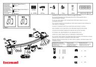
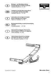
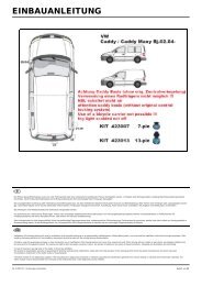
<strong>Citroen</strong> <strong>Berlingo</strong> I (1996 – 2008)<br />
Peugeot Partner I (1996 – 2008)<br />
MONTÁŽNÍ A UŽIVATELSKÝ NÁVOD<br />
MONTAGE UND BEDIENUNGSANLEITUNG<br />
USER’S GUIDE INSTALLATION INSTRUCTIONS<br />
TMB PS 045<br />
SPOJOVACÍ - TAŽNÉ ZAŘÍZENÍ<br />
VERBINDUNGS – ANHÄNGERKUPPLUNG<br />
TRAILER COUPLING DEVICE<br />
pro automobily<br />
Für Personenkraftwagen<br />
for passenger cars<br />
<strong>Citroen</strong> <strong>Berlingo</strong>, Peugeot Partner<br />
s přišroubovaným tažným ramenem<br />
mit angeschraubtem Kugelhals<br />
with bolt-on towarm<br />
e8 * 94/20 * 0082<br />
© 2.12.2008
2<br />
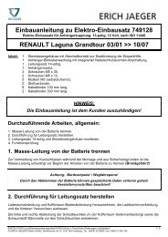
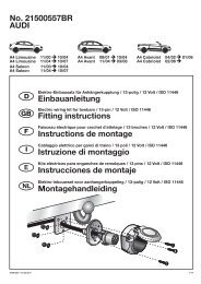
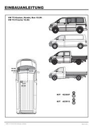
Seznam dílů tažného zařízení:<br />
Verzeichnis der Teile der Anhängerkupplung:<br />
List of components:<br />
Název dílu Kusů Pozice<br />
Bezeichnung des Teils, Name of the part Stück, Quantity Position, Positon<br />
Nosník úplný (s identifikačním štítkem)<br />
Träger vollständig (mit Identifikationsschild)<br />
Beam assembly (with ID plate) 1 1<br />
Konzola L+P (Konzole L+R, Side arm L+R) 1+1 3+2<br />
Tažné rameno (Kugelhals, Towarm) 1 4<br />
Šroub (Schraube, Bolt) M12 x 65 2 5<br />
Matice (Mutter, Nut) M12 2 6<br />
Podložka (Unterlegscheibe, Washer) ø13 2 7<br />
Šroub (Schraube, Bolt) M8 x 25 2 8<br />
Matice (Mutter, Nut) M8 2 9<br />
Podložka (Unterlegscheibe, Washer) ø8,4 2 10<br />
Podložka (Unterlegscheibe, Washer) ø8,4 2 11<br />
Šroub (Schraube, Bolt) M10 x 80 4 12<br />
Rozpěrka (Distanzrohr, Spacer) 4 13<br />
Matice (Mutter, Nut) M10 8 14<br />
Podložka (Unterlegscheibe, Washer) 10 x 40 4 15<br />
Podložka (Unterlegscheibe, Washer) ø10,5 8 16<br />
Šroub (Schraube, Bolt) M10 x 30 4 17<br />
Držák zásuvky (Steckdosenhalter, Plug box holder) 1 18<br />
Krytka kul. čepu (Kugelbolzendeckel, Cover of the ball) 1 19<br />
Samolepící štítek (Selbstklebeetikette,<br />
Self-adhesive sticker) „70 kg“ 1 -
3<br />
TAŽNÉ ZAŘÍZENÍ<br />
TMB PS 045<br />
Upozornění<br />
Díl „tažné zařízení“ , TMB PS 045 – je určen pouze k odborné montáži<br />
v autorizovaném servisu. Montáž vyžaduje použití speciálního nářadí, dílenských<br />
příruček a proto nesmí být díl „ tažné zařízení“ prodán konečnému uživateli<br />
v nenamontovaném stavu.<br />
Tažné zařízení je vyrobeno podle schválené dokumentace a odpovídá<br />
homologaci e8*94/20*0082.<br />
Všeobecné údaje<br />
Konstrukce tažného zařízení odpovídá všem mezinárodním předpisům.<br />
Zařízení prošlo pevnostními zkouškami dle evropské směrnice 94/20ES,<br />
Tažné rameno je opatřeno kulovým čepem o průměru 50 mm dle ISO 3853.<br />
Elektrická instalace pro tažné zařízení není součástí dodávky.<br />
Při montáži je nutné vyříznout otvor na spodní straně zadního nárazníku.<br />
Technické parametry<br />
Tažné zařízení je konstruováno pro:<br />
maximální povolenou hmotnost tažného vozidla 1 990 kg<br />
maximální hmotnost brzděného přívěsu 1 100 kg<br />
maximální hmotnost nebrzděného přívěsu 750 kg.<br />
max. svislé statické zatížení na kulový čep 70 kg.<br />
(Platí omezení hmotnosti přívěsu dle technického průkazu vozidla.)<br />
D C – Wert (vztažná síla) – 7 kN.<br />
T C<br />
D C<br />
g <br />
T C<br />
g – tíhové zrychlení (g = 9,81 ms -2 )<br />
T – hmotnost tažného vozidla [t]<br />
C – hmotnost přívěsu [t]<br />
Celková hmotnost tažného zařízení – 13,5 kg<br />
Rozměry<br />
1 020 x 660 x 275 mm.
Seznam speciálního nářadí :<br />
Pila pro vyříznutí otvoru do nárazníku<br />
Momentový klíč<br />
Postup montáže<br />
- Ustavte vozidlo na ramena dílenského zvedáku.<br />
- Demontujte zadní světla a obložení zav. prostoru.<br />
- Demontujte zadní nárazník (lapače nečistot jsou-li na vozidle)<br />
- Demontujte příčník zadního nárazníku.<br />
- Demontujte držák rezervního kola.<br />
4<br />
Vystřižení otvoru do zadního nárazníku<br />
- Demontovaný zadní nárazník položte na měkkou plstěnou podložku.<br />
- Na vnítřní straně nárazníku naměřte jeho střed a nakresletete rysku.<br />
- Vystřihněte papírovou šablonu přiloženou v návodu.<br />
- Přiložte papírovou šablonu na vnitřní stranu nárazníku, dle popisu na šabloně a<br />
obkreslete tvar vystřižení.<br />
- Podle vzníklé rysky vystřihněte (vyřízněte) vhodným nástrojem otvor pro tažné<br />
rameno a držák zásuvky (pozor na poškození laku nárazníku). Otvor začistěte.<br />
- Takto připravený zadní nárazník odložte na vhodné místo.<br />
Montáž tažného zařízení na vozidlo<br />
- Strhněte záslepky otvorů pro uchycení tažného zařízení na zadních podélnících<br />
(obě strany vozu). V případě potřeby odstraňte části plastizolu uvnitř podélníků.<br />
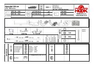
- Konzole L+P (3+2) přišroubujte pomocí čtyř šroubů M10 x 80 (12),vymezovacích<br />
trubiček (13), podložek (15 + 16) a matic M 10 (14) k podvozku vozidla.<br />
- Nosník (1) přišroubujte ke konzolám (3+2) pomocí čtyř šroubů M10 x 30 (17),<br />
podložek (16) a matic M10 (14). K zadnímu čelu přišroubujte nosník (1) pomocí<br />
dvou šroubů M8 x 25 (8), podložek (10 + 11) a matic M8 (9).<br />
- Šrouby M10 dotáhněte utahovacím momentem 65 Nm, šrouby M8 dotáhněte<br />
utahovacím momentem 35 Nm.
5<br />
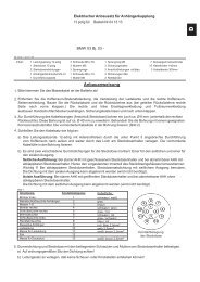
Montáž tažného ramena<br />
- Tažné rameno (4) přišroubujte pomocí šroubů M12 x 65 (5), podložek ø13 (7) a<br />
matic M12 (6) mezi držáky tažného zařízení.<br />
- Na levý držák tažného ramena pod matici (6) (blíže kulového čepu) vložte držák<br />
zásuvky (18).<br />
- Šrouby provlékněte otvorem tak, aby hlava šroubu byla na pravém držáku tažného<br />
ramena (ve směru jízdy).<br />
- Šrouby dotáhněte utahovacím momentem 80 Nm.-<br />
- Pokračujte montáží elektrické instalace tažného zatížení na vozidlo.<br />
- Po skončení montáže elektrické instalace namontujte zpět všechny demontované<br />
díly a příslušné spoje utáhněte předepsanými utahovacími momenty.<br />
- Na zadní nárazník nad tažné rameno nalepte samolepicí štítek “70 kg” (příslušné<br />
místo před nalepením očistěte a odmastěte).<br />
- Na kulový čep tažného zařízení nasaďte krytku (19).
6<br />
ANHÄNGERKUPPLUNG<br />
TMB PS 045<br />
Hinweis<br />
Das Teil „Anhängerkupplung“ , TMB PS 045 – ist ausschließlich zur<br />
Fachmontage in einem autorisierten Service bestimmt. Die Montage erfordert<br />
die Verwendung spezieller Werkzeuge und Werkstättenhandbücher. Deswegen darf<br />
das Teil „Anhängerkupplung“ dem Endverbraucher nicht in unverbautem Zustand<br />
verkauft werden.<br />
Die Anhängerkupplung ist nach genehmigter Dokumentation gefertigt worden<br />
und entspricht der Typengenehmigung e8*94/20*0082.<br />
Allgemeine Angaben<br />
Die Konstruktion der Anhängerkupplung entspricht allen tschechischen und<br />
internationalen Vorschriften.<br />
Die Einrichtung wurde Festigkeitsproben laut der europäischen Richtlinie<br />
94/20/EG unterzogen.<br />
Der Kugelhals ist mit einem Kugelbolzen mit einem Durchmesser von 50 mm laut<br />
ISO 3853 versehen.<br />
Die Elektroinstallation der Zugvorrichtung bildet keinen<br />
Lieferungsbestandteil.<br />
Bei der Montage ist eine Öffnung auf der Unterseite des Heckstoßfängers<br />
auszuschneiden.<br />
Technische Parameter<br />
Die Anhängerkupplung ist konstruiert für:<br />
- maximal erlaubtes Gewicht des Zugsfahrzeugs 1 990 Kg<br />
- Maximalgewicht des gebremsten Anhängers 1 100 Kg<br />
- Maximalgewicht des ungebremsten Anhängers 750 Kg<br />
Die maximale senkrechte statische Belastung des Kugelbolzens beträgt 70 Kg<br />
(Es gelten die Gewichtseinschränkungen des Anhängers laut<br />
Fahrzeugszulassungsschein)<br />
D C – Wert (Bezugskraft) – 7 kN.<br />
D C<br />
T C<br />
g <br />
T C<br />
g – Lastbeschleunigung (g = 9,81 ms -2 )<br />
T – Gewicht des Zugfahrzeugs [t]<br />
C – Anhängergewicht [t]<br />
Gesamtgewicht der Anhängerkupplung – 13,5 kg<br />
Maße<br />
1 020 x 660 x 275 mm.
Verzeichnis Spezialwerkzeug:<br />
Säge für das Ausschneiden einer Öffnung in den Stoßfänger<br />
Drehmomentschlüssel<br />
Montageablauf<br />
- Setzen Sie das Fahrzeug auf die Arme eines Werkstättenhebers.<br />
- Demontieren Sie die Heckleuchten und die Gepäckraumverkleidung<br />
- Nehmen Sie den Heckstoßfänger (Schmutzfänger, soweit auf dem Fahrzeug<br />
befindlich)<br />
- Nehmen Sie den Querträger des Heckstoßfängers ab.<br />
- Demontieren Sie die Ersatzradhalterung.<br />
7<br />
Ausschneiden der Öffnung in den Heckstoßfänger<br />
- Der demontierte Heckstoßfänger ist auf eine weiche Filzunterlage zu legen.<br />
- Messen Sie auf der Innenseite des Stoßfängers seine Mitte aus und zeichnen Sie<br />
eine Strichmarke ein.<br />
- Schneiden Sie die in der Anleitung beiliegende Papierschablone aus.<br />
- Legen Sie die Papierschablone auf die Innenseite des Stoßfängers laut der<br />
Beschreibung auf der Schablone und zeichnen Sie die Ausschnittform ab.<br />
- Schneiden Sie mit einem geeigneten Werkzeug eine Öffnung für den Deichselarm<br />
und den Steckdosenhalter nach der entstandenen Strichmarke aus. (Achtung auf<br />
Lackbeschädigungen des Stoßfängers) Die Öffnung ist zu säubern.<br />
- Legen sie den so vorbereiteten Stoßfänger auf einen geeigneten Platz beiseite.<br />
Montage der Anhängerkupplung auf das Fahrzeug<br />
- Reißen Sie die Verblendungen der Öffnungen für die Befestigung der<br />
Anhängerkupplung auf den hinteren Längsseiten ab (beide Fahrzeugsseiten).<br />
Entfernen Sie im Bedarfsfall Plastisolteile aus dem Innerern der Längsträger.<br />
- Konzole L+R (3+2) befestigen Sie mittels 4 Schrauben M10x80 (12), der<br />
Distanzröhre (13), der Unterlegscheiben (15 + 16) und M10 Muttern (14) zum<br />
Fahrgestell.<br />
- Den Träger (1) befestigen Sie zu den Konzolen (3 + 2) mittels 4 Schrauben<br />
M10x30 (17), Unterlegscheiben (16), und M10 Muttern (14). Zu hinterer Stirn<br />
verschrauben Sie den Träger (1) mittels 2 Schrauben M8x25 (8), Unterlegscheiben<br />
(10 + 11) und M8 Muttern (9).<br />
- M10 Schraube ziehen Sie durch Anzugsmoment 65 Nm und die M8 Schraube<br />
ziehen Sie durch Anzugsmoment 35 Nm an.
8<br />
Montage des Kugelhals<br />
- Schrauben Sie den Kugelhals (4) mit Hilfe der Schrauben M12 x 65 (5), Unterlagen ø 13<br />
(7) und Muttern M12 (6) zwischen die Halter der Anhängerkupplung. Legen Sie auf den<br />
linken Halter des Kugelhals unter die Mutter (6) (näher zum Kugelbolzen) den<br />
Steckdosenhalter (18). Ziehen Sie die Schrauben durch die Öffnung so durch, dass der<br />
Schraubenkopf auf dem rechten Kugelhals (in Fahrrichtung) aufliegt.<br />
- Ziehen Sie die Schrauben mit einem Anziehmoment von 80 Nm nach.-<br />
- Setzen Sie die Montage der Elektroinstallation der Zugbelastung auf das Fahrzeug fort.<br />
- Bauen Sie nach Beendung der Montage der Elektroinstallation alle demontierten Teile<br />
wieder auf und ziehen Sie sie mit den vorgeschriebenen Anziehmomenten nach.<br />
Kleben Sie auf den Heckstoßfänger über dem Kugelhals das Selbstklebeetickett “70 kg”<br />
(die zuständige Stelle ist vor dem Aufkleben zu reinigen und zu entfetten).<br />
- Setzen Sie auf den Kugelbolzen der Anhängerkupplung den Deckel auf (19).
9<br />
COUPLING DEVICE<br />
TMB PS 045<br />
Important:<br />
The part called „COUPLING DEVICE“ type TMB PS 045 – can be mounted only by an<br />
authorized service station. The intallation requires special tools and workshop manuals and<br />
for this reason the part „COUPLING DEVICE“ is not allowed to be sold to any enduser<br />
free without installing.<br />
The coupling device is made according to approved documentation and complies with<br />
the homologation e8*94/20*0082.<br />
General data<br />
The design of the coupling device complies with all international standards<br />
The coupling device passed all structure tests as stipulated in 94/20/EC,<br />
The towarm has a ball pivot ø 50mm ISO 3853.<br />
Electrical wiring is not included in this set<br />
For mounting it is necessary to cut a hole at the bottom of the rear fender.<br />
Technical data and parameters<br />
The device is designed for:<br />
total permitted weight of the towing vehicle<br />
braked trailers - maximum towed load<br />
unbraked trailer maximum towed load<br />
max. nose static weight on the ball pivot<br />
1 990 kg<br />
1 100 kg<br />
750 kg<br />
70 kg<br />
Mind the limits of the tow load in the registration certificate<br />
D C – reference dynamic force<br />
T C<br />
D C<br />
g <br />
T C<br />
g – gravitational acceleration (g = 9,81 ms -2 )<br />
T – towing car weight [t]<br />
C – trailer’s weight [t]<br />
7 kN.<br />
Total weight of the coupling device – 13,5 kg<br />
Dimensions<br />
1 020 x 660 x 275 mm.<br />
List of special tools and gadgets:<br />
Suitable cutter for making an opening in the rear buffer<br />
Torque wrench
Installing procedure<br />
- Position the car on the garage jack’s arms.<br />
- Dismount the tail lamps and the boot’s padding.<br />
- Dismount the rear bumper ( and plastic mudguards if present).<br />
- Dismount the crossbeam of the rear bumper.<br />
- Dismount the stepney holder.<br />
10<br />
Cutting an opening in the back bumper:<br />
- Dismounted back bumper is placed on a soft pad .<br />
- Measure and score the center of the bumper on the bottom side.<br />
- Cut out a paper template enclosed in the manual.<br />
- Place the paper template on the internal side of the bumper as drawn on the template and<br />
mark the shape.<br />
- Cut out an opening for the towbar and plugbox holder in the bumper by a suitable tool<br />
(beware of scratching the outer surface) and clean the edge of the hole.<br />
-Put off the prepared bumper on a suitable place.<br />
Mounting the equipment onto the car :<br />
-Take out the blinds from the pre-bored holes in the sills on both sides of the car<br />
underbody. If necessary, clean the interior of the holes from the deposits of plastic<br />
protection.<br />
- Screw up the side arms Left (3) + Right (2) with four bolts M10 x 80 (12), spacers (13),<br />
washers (15+16) and nuts M10 (14) onto the underbody.<br />
- Screw up the beam (1) to the side arms (3+2) with four bolts M10 x 30 (17), washers (16)<br />
and nuts M10 (14). To the rear wall screw up the beam (1) with two bolts M8 x 25 (8),<br />
washers (10+11) and nuts M8 (9).<br />
- Tighten the bolts M10 by torque 65 Nm, the bolts M8 by torque 35 Nm.<br />
Mounting the towarm<br />
- The towarm (4) is fixed by the bolts M12 x 65 (5), washers ø13 (7) and nuts M12 (6)<br />
between the brackets of the coupling device.<br />
- Fasten the plugbox holder (18) onto the left holder of the towarm under the nut (6) (more<br />
closely to the ball pivot).<br />
- Put the bolts into the holes so that their heads remain on the right bracket (if looking<br />
ahead);<br />
- Tighten the bolts by the prescribed torque : 80 Nm.-<br />
- Further step is the installation of electric wiring.<br />
- After installing the cable harness remount back all dismantled parts and tighten the<br />
appropriate joints by the respective torques.<br />
- Put a self-adhesive sticker “70 kg” on the back bumper- above the towarm (clean and<br />
degrease the appropriate place for the sticker).<br />
- Place a lid onto the ball pivot of the towarm (19).
12<br />
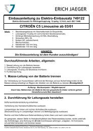
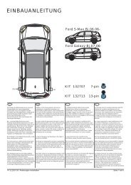
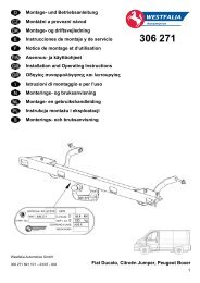
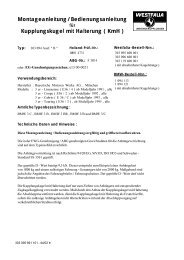
Šablona Schablone Template
13<br />
Upozornění pro zákazníka<br />
- Dotažení šroubů (5) upevňujících tažné rameno (4) kontrolujte pravidelně po<br />
ujetí cca 1000 km!<br />
- Kulový čep občas namažte vhodným mazacím tukem.<br />
- Po připojení přívěsu zasuňte zástrčku (od přívěsu) do zásuvky tažného zařízení a<br />
zkontrolujte funkci světel na přívěsu.<br />
- Veškeré změny a úpravy tažného zařízení jsou nepřípustné.<br />
- Při používání tažného zařízení dodržujte pokyny uvedené v tomto návodu.<br />
- Výrobce na sebe nebere zodpovědnost za škody způsobené chybně namontovaným<br />
tažným ramenem, jeho přetěžováním nebo poškozením při havárii vozidla.<br />
- Tažné zařízení nesmí být provozováno je-li poškozeno nebo je neúplné.<br />
- Není-li připojen přívěsný vozík k tažnému zařízení, musí být kulový čep chráněn<br />
krytkou!<br />
- Tažné rameno (pokud ho budete demontovat) uložte a zajistěte v zavazadlovém<br />
prostoru tak, aby při náhlém zabrždění nemohlo ohrozit bezpečnost cestujících a<br />
způsobit poškození zavazadlového prostoru. Na kulový čep tažného ramena nasaďte<br />
krytku.<br />
- Po ujetí prvních asi 500 km s přívěsem je nutné zkontrolovat dotažení upínacích<br />
šroubů nosníku k podvozku vozidla a dotažení tažného ramena a případně je<br />
dotáhnout předepsanými utahovacími momenty! Tuto kontrolu Vám doporučujeme<br />
provést v nejbližším autorizovaném servisu.<br />
Hinweis für den Kunden<br />
- Kontrollieren Sie regelmäßig die Nachspannung der den Kugelhals (4) befestigenden<br />
Schrauben (5) nach Zurücklegen von cca 1000 km!<br />
- Schmieren Sie den Kugelbolzen hin und wieder mit einem geeigneten Schmierfett<br />
ein.<br />
- Schieben Sie nach Anhängeranschluss den Stecker (des Anhängers) in die Steckdose<br />
der Anhängerkupplung und überprüfen Sie die Funktionstüchtigkeit der Lichter auf<br />
dem Anhänger.<br />
- Sämtliche Änderungen und Modifizierungen der Anhängerkupplung sind<br />
unzulässig.<br />
- Halten Sie bei der Verwendung der Anhängerkupplung die in dieser Anleitung<br />
enthaltenen Anweisungen ein.<br />
- Der Hersteller nimmt keinerlei Verantwort für Schäden auf sich, die durch eine<br />
fehlerhaft angebaute Anhängerkupplung verursacht wurden, ihre Überbelastung oder<br />
die Beschädigung beim Fahrzeugsunfall.<br />
- Die Anhängerkupplung darf nicht betrieben werden, falls sie beschädigt oder<br />
unvollständig ist.<br />
- Falls kein Anhänger an die Anhängerkupplung angeschlossen ist, muss der<br />
Kugelbolzen mit einer Haube geschützt werden!
14<br />
- Der Kugelhals (falls Sie ihn anbauen werden) ist im Gepäckraum so abzulegen und<br />
so zu sichern, dass er beim plötzlichen Bremsen die Sicherheit der Reisenden nicht<br />
gefährdet und den Gepäckraum nicht beschädigt. Setzen Sie auf den Kugelbolzen des<br />
Kugelhals eine Haube auf.<br />
- Nach Zurücklegen der ersten ungefähr 500 km mit Anhänger ist die Anzugskraft<br />
der Spannschrauben des Trägers an das Fahrgestell des Fahrzeugs und die<br />
Nachspannung des Kugelhals zu überprüfen und gegebenenfalls mit den<br />
vorgeschriebenen Anziehmomenten nachzuziehen! Wir empfehlen diese Kontrolle im<br />
nächstgelegenen autorisierten Service vorzunehmen.<br />
Notice to the customers<br />
- Tightening of the bolts (5) fixing the towarm (4) must be checked regularly after<br />
each 1000 km!<br />
- The ball of the towarm should be occasionally cleaned and greased by a suitable<br />
lubricant.<br />
- Check the function of all lights on the trailer after coupling the trailer and pluging<br />
the trailer to the plugbox on the towing vehicle.<br />
- Any alternations of the towing equipment are not allowed.<br />
- Follow the instructions of this guide while using the coupling device.<br />
-The producer cannot take over any responsibility for any damage resulting from<br />
improper installation of the towarm, its overloading or a crash of the car. – The<br />
coupling device cannot be used if damaged or incomplete.<br />
- In case of the trailer not being coupled with the car, the ball pivot must be<br />
protected by a plastic cover!<br />
- The towarm (in case it is removed from the brackets) should be stored properly in in<br />
boot to prevent damgage to the car or any injury of the passangers at sudden braking.<br />
The ball pivot shoult be covered by its plastic cover.<br />
- After running the first about 500 km with a trailer it is necessary to re-tighten the<br />
bolts fixing the crossbeam to the car underbody and the towarm with the prescribed<br />
torques! We recoment to have this check done in your nearest authorized service<br />
station.
15<br />
Záruční list<br />
Výrobce tažného zařízení poskytuje záruku na konstrukci, použitý materiál, výrobní<br />
provedení a funkci dodaného tažného zařízení 24 měsíců od data prodeje.<br />
Reklamaci výrobku v zákonné lhůtě uplatní kupující u prodávajícího. Oprávněnost<br />
reklamace posoudí zástupce prodávajícího spolu se zástupcem výrobce v souladu<br />
s platnými předpisy.<br />
Podmínkou platnosti záruky je, aby tažné zařízení bylo používáno pouze k účelům, ke<br />
kterým je určeno.<br />
Kupující je povinen prověřit stav zboží při jeho převzetí. V případě poškození zboží,<br />
nedodání části tažného zařízení apod. je kupující povinen tuto skutečnost neprodleně ohlásit<br />
prodávajícímu a to bez zbytečného odkladu po převzetí zboží.<br />
Všechny součásti a příslušenství tažného zařízení musí být před odbornou montáží,<br />
zkontrolovány ve vztahu k jejich kompaktibilitě na odpovídající typ vozidla. Tažná<br />
zařízení, smí být použita pouze na výrobcem uvedený typ vozidla. V případě neodborné<br />
montáže či montáže tažného zařízení na typ vozidla, pro který není tažné zařízení určeno,<br />
neodpovídá výrobce za případné poškození tažného zařízení, způsobené vadnou montáží či<br />
jeho nesprávným použitím.<br />
Prodávající odpovídá za vady, které mělo tažné zařízení při jeho převzetí kupujícím.<br />
Záruka se nevztahuje na škody mající původ v běžném opotřebení, v přetěžování a<br />
neodborném používáním tažného zařízení, dále pokud není užíváno v souladu s pokyny<br />
uvednými v návodu k obsluze. Záruka se dále nevztahuje na škody způsobené živelnými<br />
vlivy. Prodávající rovněž neodpovídá za škodu v případě, kdy bylo tažné zařízení změněno<br />
či jinak upraveno.<br />
Záruka zaniká, bylo-li tažné zařízení poškozeno havárií (kromě havárie vyvolané<br />
samotným tažným zařízením) nebo zásahy do jeho mechanismu a konstrukce.
16<br />
Garantieinformationen und Bedingungen<br />
Der Hersteller der Anhängerkupplung gewährt auf Konstruktion, verwendetes Material,<br />
Produktionsausführung und Funktion der gelieferten Anhängerkupplung eine Garantie von<br />
24 Monaten ab Verkaufsdatum.<br />
Die Reklamation des Produkts in der gesetzlichen Frist macht der Käufer beim Verkäufer<br />
geltend. Die Berechtigung der Reklamation beurteilt ein Vertreter des Verkäufers<br />
zusammen mit einem Vertreter des Herstellers entsprechend der gültigen Vorschriften.<br />
Bedingung für die Gültigkeit der Garantie ist, dass die Anhängerkupplung zum für sie<br />
bestimmten Zweck angewendet wurde.<br />
Der Käufer ist verpflichtet, den Zustand der Ware bei Übernahme zu überprüfen. Bei<br />
Beschädigung der Ware, fehlendem Teil der Anhängerkupplung, u.ä. ist der Käufer<br />
verpflichtet, diese Tatsache unverzüglich dem Verkäufer zu melden, dies ohne unnötigen<br />
Verzug nach Warenübernahme.<br />
Alle Teile und das Zubehör der Anhängerkupplung muss vor der fachgerechten Montage in<br />
Beziehung zur Kompatibilität für den entsprechenden Fahrzeugtyp kontrolliert werden.<br />
Anhängerkupplungen dürfen nur am vom Hersteller angeführten Fahrzeugtyp benutzt<br />
werden. Bei nicht fachgerechter Montage oder Montage der Anhängerkupplung an einen<br />
Fahrzeugtyp, für welchen sie nicht bestimmt ist, haftet der Hersteller nicht für eventuelle<br />
Beschädigungen der Anhängerkupplung, verursacht durch fehlerhafte Montage oder falsche<br />
Benutzung.<br />
Der Verkäufer haftet für Mängel, welche die Anhängerkupplung bei Übernahme durch den<br />
Käufer hatte.<br />
Die Garantie bezieht sich nicht auf Schäden, die ihre Ursache in normalem Verschleiß,<br />
Überlastung und nicht fachgerechter Benutzung der Anhängerkupplung haben, weiter wenn<br />
sie nicht gemäß der Anweisungen in der Gebrauchsanleitung benutzt wurde. Die Garantie<br />
bezieht sich weiter nicht auf durch Naturkatastrophen verursachte Schäden. Der Verkäufer<br />
haftet ebenfalls nicht für Schaden, wenn die Anhängerkupplung geändert oder angepasst<br />
wurde.<br />
Die Garantie erlischt, wenn die Anhängerkupplung durch einen Unfall beschädigt wurde<br />
(außer einem Unfall, hervorgerufen durch die Anhängerkupplung) oder bei Eingriff in ihren<br />
Mechanismus und Konstruktion.
17<br />
Guarantee information and conditions<br />
The manufacturer of the towing coupling gives the guarantee for the construction, used<br />
material, manufacturing execution and function of the supplied towing coupling for 24<br />
months from the date of sale.<br />
The complaints are to be presented by the buyer to the selling organization within the legal<br />
period. The rightfulness of the complaint will be judged by a representative of the selling<br />
organization together with a representative of the manufacturer in accordance with valid<br />
regulations.<br />
The prerequisite of validity of the guarantee is that the towing coupling has to be used only<br />
for those purposes for which it is designed.<br />
The buyer shall examine the condition of the goods at their reception. In case of any<br />
damage of the goods or failure to deliver any part of the towing coupling the buyer shall<br />
report such fact immediately to the selling organization without unnecessary delay after the<br />
reception of the goods.<br />
All parts and accessories of the towing coupling must be checked before professional fitting<br />
with regard to their compatibility with the respective type of vehicle. The towing couplings<br />
may be used only for the vehicle type stated by the manufacturer. In case of incompetent<br />
fitting or fitting of the towing coupling on a type of vehicle for which the towing coupling<br />
is not intended, the manufacturer shall not be responsible for any damage of the towing<br />
coupling caused by defective fitting or its incorrect use.<br />
The selling organization is responsible for defects the towing coupling had at its reception<br />
by the buyer.<br />
The guarantee does not cover any damages resulting from common wear and tear,<br />
overloading and unprofessional use, as well as damages caused by non-compliance with the<br />
instructions stated in the operating manual. The guarantee does not cover any damages due<br />
to natural disasters. The selling organization is not responsible for any damage in the case<br />
when the towing coupling was modified or otherwise altered.<br />
The guarantee also becomes void if the towing coupling has been damaged due to an<br />
accident (except accidents caused by the towing coupling itself) or by tampering with its<br />
mechanism and construction.
Záruční list/ Garantieschein/ Certificate of guarantee<br />
20<br />
Výrobní číslo: .......................................................<br />
Produktionsnummer:<br />
Production No:<br />
Datum výroby: .......................................................<br />
Produktoinsdatum:<br />
Date of production:<br />
Výstupní kontrola výrobce: .......................................................<br />
Ausgangskontrolle des Herstellers:<br />
Final inspection of the manufacturer:<br />
Datum prodeje: .......................................................<br />
Verkaufsdatum:<br />
Date of sale:<br />
Prodávající: ...........................................................<br />
Verkäufer:<br />
(Razítko a podpis prodávajícího)<br />
Seller:<br />
(Stempel und Unterschrift des Verkäufers)<br />
(Stamp and signature of the seller)<br />
Výrobce: Manufacturer: Hersteller:<br />
PROF SVAR s.r.o., Přestavlcká 1474, CZ - 295 01 Mnichovo Hradiště,<br />
Tel.: +420 326 771 704 Fax.: +420 326 771 230 E-mail: profsvar@profsvar.cz<br />
4<br />
LDPE