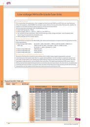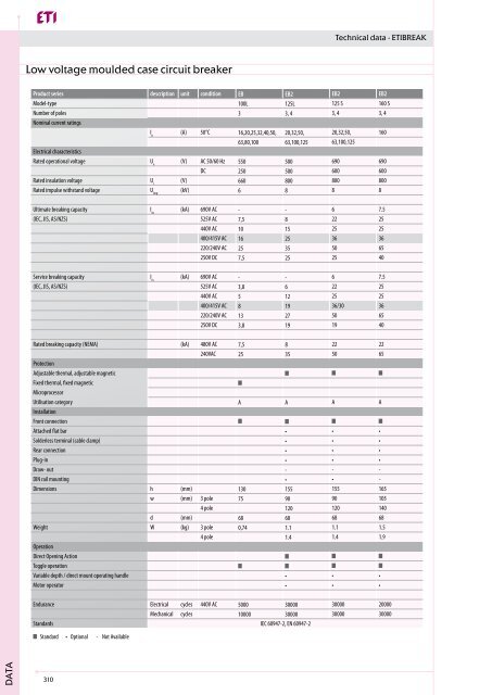
Low voltage moulded case circuit breaker - Eti-de.de
Low voltage moulded case circuit breaker - Eti-de.de
Low voltage moulded case circuit breaker - Eti-de.de

You also want an ePaper? Increase the reach of your titles
YUMPU automatically turns print PDFs into web optimized ePapers that Google loves.
Technical data - ETIBREAK<br />
<strong>Low</strong> <strong>voltage</strong> <strong>moul<strong>de</strong>d</strong> <strong>case</strong> <strong>circuit</strong> <strong>breaker</strong><br />
Product series <strong>de</strong>scription unit condition EB EB2 EB2 EB2<br />
Mo<strong>de</strong>l-type 100L 125L 125 S 160 S<br />
Number of poles 3 3, 4 3, 4 3, 4<br />
Nominal current ratings<br />
I n<br />
(A) 50°C 16,20,25,32,40,50, 20,32,50, 20,32,50, 160<br />
63,80,100 63,100,125 63,100,125<br />
Electrical characteristics<br />
Rated operational <strong>voltage</strong> U e<br />
(V) AC 50/60 Hz 550 500 690 690<br />
DC 250 500 600 600<br />
Rated insulation <strong>voltage</strong> U i<br />
(V) 660 800 800 800<br />
Rated impulse withstand <strong>voltage</strong> U imp<br />
(kV) 6 8 8 8<br />
Ultimate breaking capacity I cu<br />
(kA) 690V AC - - 6 7.5<br />
(IEC, JIS, AS/NZS) 525V AC 7,5 8 22 25<br />
440V AC 10 15 25 25<br />
400/415V AC 16 25 36 36<br />
220/240V AC 25 35 50 65<br />
250V DC 7,5 25 25 40<br />
Service breaking capacity I cs<br />
(kA) 690V AC - - 6 7.5<br />
(IEC, JIS, AS/NZS) 525V AC 3,8 6 22 25<br />
440V AC 5 12 25 25<br />
400/415V AC 8 19 36/30 36<br />
220/240V AC 13 27 50 65<br />
250V DC 3,8 19 19 40<br />
Rated breaking capacity (NEMA) (kA) 480V AC 7,5 8 22 22<br />
240VAC 25 35 50 65<br />
Protection<br />
Adjustable thermal, adjustable magnetic<br />
Fixed thermal, fixed magnetic<br />
Microprocessor<br />
Utilisation category A A A A<br />
Installation<br />
Front connection<br />
Attached flat bar • • •<br />
Sol<strong>de</strong>rless terminal (cable clamp) • • •<br />
Rear connection • • •<br />
Plug-in • • •<br />
Draw- out - - -<br />
DIN rail mounting • • -<br />
Dimensions h (mm) 130 155 155 165<br />
w (mm) 3 pole 75 90 90 105<br />
4 pole 120 120 140<br />
d (mm) 68 68 68 68<br />
Weight W (kg) 3 pole 0,74 1.1 1.1 1.5<br />
4 pole 1.4 1.4 1.9<br />
Operation<br />
Direct Opening Action<br />
Toggle operation<br />
Variable <strong>de</strong>pth / direct mount operating handle • • •<br />
Motor operator • • •<br />
Endurance Electrical cycles 440V AC 5000 30000 30000 20000<br />
Mechanical cycles 10000 30000 30000 30000<br />
Standards IEC 60947-2, EN 60947-2<br />
Standard • Optional - Not Available<br />
DATA<br />
310
Technical data - ETIBREAK<br />
Product series <strong>de</strong>scription unit condition EB2 EB2 EB2<br />
Mo<strong>de</strong>l-type 250L 250S 250E<br />
Number of poles 3, 4 3, 4 3, 4<br />
Nominal current ratings<br />
I n<br />
(A) 50°C 200, 250 200, 250 40, 125, 160, 250<br />
Electrical characteristics<br />
Rated operational <strong>voltage</strong> U e<br />
(V) AC 50/60 Hz 500 690 690<br />
DC 500 600 -<br />
Rated insulation <strong>voltage</strong> U i<br />
(V) 800 800 800<br />
Rated impulse withstand <strong>voltage</strong> U imp<br />
(kV) 8 8 8<br />
Ultimate breaking capacity I cu<br />
(kA) 690V AC - 7.5 20<br />
(IEC, JIS, AS/NZS) 525V AC 10 25 35<br />
440V AC 15 25 50<br />
400/415V AC 25 36 70<br />
220/240V AC 35 65 125<br />
250V DC 25 40 -<br />
Service breaking capacity I cs<br />
(kA) 690V AC - 7.5 15<br />
(IEC, JIS, AS/NZS) 525V AC 7.5 25 35<br />
440V AC 12 25 50<br />
400/415V AC 19 36 70<br />
220/240V AC 27 65 125<br />
250V DC 19 40 -<br />
Rated breaking capacity (NEMA) (kA) 480V AC 10 22 35<br />
240VAC 35 65 125<br />
Rated short-time withstand current I cw<br />
(kA) 0.3 seconds - - -<br />
Protection<br />
Adjustable thermal, adjustable magnetic<br />
Fixed thermal, fixed magnetic<br />
Microprocessor<br />
Utilisation category A A A<br />
Installation<br />
Front connection<br />
Attached flat bar • • •<br />
Sol<strong>de</strong>rless terminal (cable clamp) • • •<br />
Rear connection • • •<br />
Plug-in • • •<br />
Draw- out - - -<br />
DIN rail mounting - - -<br />
Dimensions h (mm) 165 165 165<br />
w (mm) 3 pole 105 105 105<br />
(mm) 4 pole 140 140 140<br />
d (mm) 68 68 103<br />
Weight W (kg) 3 pole 1.5 1.5 2.5<br />
4 pole 1.9 1.9 3.3<br />
Operation<br />
Direct Opening Action<br />
Toggle operation<br />
Variable <strong>de</strong>pth / direct mount operating handle • • •<br />
Motor operator • • •<br />
Endurance Electrical cycles 415V AC 10000 10000 10000<br />
Mechanical cycles 30000 30000 30000<br />
Standards IEC 60947-2, EN 60947-2<br />
Standard • Optional - Not Available<br />
311<br />
DATA
Technical data - ETIBREAK<br />
Product series <strong>de</strong>scription unit condition EB2 EB2 EB2 EB2 EB2<br />
Mo<strong>de</strong>l-type 400L 400S 400E 630LE 630E<br />
Number of poles 3, 4 3, 4 3,4 3,4 3, 4<br />
Nominal current ratings<br />
I n (A) 50°C 250, 250, 250, 630 630<br />
400 400 400<br />
Electrical characteristics<br />
Rated operational <strong>voltage</strong> U e (V) AC 50/60 Hz 500 690 690 690* 690*<br />
DC 500 600 - - -<br />
Rated insulation <strong>voltage</strong> U i (V) 800 800 800 800 800<br />
Rated impulse withstand <strong>voltage</strong> U imp (kV) 8 8 8 8 8<br />
Ultimate breaking capacity I cu (kA) 690V AC - 20 20 10* 20*<br />
(IEC, JIS, AS/NZS) 525V AC 15 30 30 15 30<br />
440V AC 22 45 45 25 45<br />
400/415V AC 25 50 50 36 50<br />
220/240V AC 35 85 85 50 85<br />
250V DC 25 40 - - -<br />
Service breaking capacity I cs (kA) 690V AC - 15 15 10* 15*<br />
(IEC, JIS, AS/NZS) 525V AC 15 30 30 15 30<br />
440V AC 22 45 45 25 45<br />
400/415V AC 25 50 50 36 50<br />
220/240V AC 35 85 85 50 85<br />
250V DC 19 40 - - -<br />
Rated breaking capacity (NEMA) (kA) 480V AC 15 25 25 15 25<br />
240VAC 35 85 85 50 85<br />
Rated short-time withstand current I cw (kA) 0.3 seconds - - 5 - -<br />
Protection<br />
Adjustable thermal, adjustable magnetic<br />
Fixed thermal, fixed magnetic<br />
Microprocessor<br />
Utilisation category A A B A A<br />
Installation<br />
Front connection<br />
Attached flat bar • • • • •<br />
Sol<strong>de</strong>rless terminal (cable clamp) • • • - -<br />
Rear connection • • • - -<br />
Plug-in • • •<br />
Draw- out • • • - -<br />
DIN rail mounting - - - - -<br />
Dimensions h (mm) 260 260 260 260 260<br />
w (mm) 3 pole 140 140 140 140 140<br />
(mm) 4 pole 185 185 185 185 185<br />
d (mm) 103 103 103 103 103<br />
Weight W (kg) 3 pole 4.2 4.2 4.3 5.0 5.0<br />
4 pole 5.6 5.6 5.7 6.5 6.5<br />
Operation<br />
Direct Opening Action<br />
Toggle operation<br />
Variable <strong>de</strong>pth / direct mount operating handle • • • • •<br />
Motor operator • • • • •<br />
Endurance Electrical cycles 415V AC 4500 4500 4500 4500 4500<br />
Mechanical cycles 15000 15000 15000 15000 15000<br />
Standards IEC 60947-2, EN 60947-2<br />
Standard • Optional - Not Available<br />
DATA<br />
312
Technical data - ETIBREAK<br />
Ratings and specifications<br />
Ampere Frame 630/800 630/800 1250 1600<br />
Type EB630 EB800 EB1250 EB1600<br />
Rated current I n<br />
[A] NRC ASR NRC ASR NRC ASR NRC ASR<br />
Calibrated at 45°C<br />
630<br />
Min Max<br />
400 630 800<br />
Min Max<br />
500 800 1000<br />
1250<br />
Min Max<br />
500 1000<br />
630 1250<br />
1600<br />
Min Max<br />
800 1600<br />
Rated impulse withstand <strong>voltage</strong> U imp<br />
[kV] 8 8 8 8<br />
AC Rated insulation <strong>voltage</strong> U i<br />
[V] 690 690 690 690<br />
AC rated breaking capacity sym. r.m.s. [kA]<br />
IEC 947-2 (I cu<br />
)/IEC 947-2 ( Ics<br />
) 690 V 20/10 20/10 25/19 35/35<br />
500 V 35/18 35/18 45/34 65/49<br />
440 V 50/25 50/25 65/49 85/64<br />
415 V 50/25 50/25 65/49 85/64<br />
400 V 65/33 65/33 85/64 100/75<br />
380 V 65/33 65/33 85/64 100/75<br />
240 V 85/43 85/43 100/75 125/94<br />
NEMA AB-1 600 V 30 30 42 65<br />
480 V 50 50 65 85<br />
240 V 85 85 85 125<br />
DC rated breaking capacity (kA)<br />
250 V 50 50 - -<br />
125 V 50 50 - -<br />
Outline dimensions (mm)<br />
W<br />
d2<br />
W (width) 210 280 210 280 210 280 210 280<br />
d1<br />
H (high) 273 273 370 370<br />
D1 (<strong>de</strong>pth) 103 103 120 140<br />
D2 (<strong>de</strong>pth with handle) 145 145 171 191<br />
Weight (kg) 9,0 11,5 9,4 12,2 22 28 27 35<br />
Connections flat Bar flat Bar flat Bar flat Bar<br />
Test button yes yes yes yes<br />
Protective functions<br />
Thermal unit adjustable adjustable adjustable adjustable<br />
Magnetic unit adjustable adjustable adjustable adjustable<br />
Standards IEC 60947-2, EN 60947-2<br />
NRC: nominal rated current<br />
ASR: adjustable setting range<br />
h<br />
313<br />
DATA
Technical data - ETIBREAK<br />
Product series <strong>de</strong>scription unit condition EB2R EB2R<br />
Mo<strong>de</strong>l-type 125L 250L<br />
Number of Poles 3, 4 3, 4<br />
Nominal current ratings<br />
I n<br />
(A) 50°C 20, 32, 50 160, 250<br />
63, 100, 125<br />
Electrical characteristics<br />
Rated operational <strong>voltage</strong> U e<br />
(V) AC 50/60 Hz 525 525<br />
Rated impulse withstand <strong>voltage</strong> U imp<br />
(kV) 8 8<br />
Ultimate breaking capacity I cu<br />
(kA) 525V AC 8 10<br />
(IEC, JIS, AS/NZS) 440V AC 15 15<br />
400/415V AC 25 25<br />
220/240V AC 35 35<br />
Service breaking capacity I cs<br />
(kA) 525V AC 6 7.5<br />
(IEC, JIS, AS/NZS) 440V AC 12 12<br />
400/415V AC 19 19<br />
220/240V AC 27 27<br />
Protection<br />
Adjustable thermal, adjustable magnetic<br />
Residual current potection, Type A<br />
Utilization category A A<br />
Installation<br />
Front connection<br />
Attached flat bar • •<br />
Sol<strong>de</strong>rless terminal (cable clamp) • •<br />
Rear connection • •<br />
Plug-in - -<br />
DIN rail mounting • -<br />
Dimensions h (mm) 155 165<br />
w (mm) 3 pole 90 105<br />
4 pole 120 140<br />
d (mm) 68 68<br />
Weight W (kg) 3 pole 1.1 1.5<br />
4 pole 1.4 1.9<br />
Operation<br />
Direct Opening Action<br />
Toggle operation<br />
Variable <strong>de</strong>pth / direct mount operating handle • •<br />
Mechanical interlocks - -<br />
Motor operator • •<br />
Endurance Electrical cycles 440V AC 30000 30000<br />
Mechanical cycles 30000 30000<br />
Standards IEC 60947-2, EN 60947-2<br />
Standard • Optional - Not Available<br />
Note: All ratings are guaranteed when the <strong>de</strong>vice is reverse - connected!<br />
DATA<br />
314
Technical data - ETIBREAK<br />
<strong>Low</strong> <strong>voltage</strong> switch disconnector<br />
Product series <strong>de</strong>scription unit condition ED2 ED2 ED2 ED2 ED2<br />
Mo<strong>de</strong>l-type 125 160 250 400 630<br />
Number of Poles 3, 4 3, 4 3,4 3,4 3, 4<br />
Nominal current ratings<br />
I n (A) 125 160 250 400 630<br />
Electrical characteristics<br />
Rated operational <strong>voltage</strong> U e (V) AC 50/60 Hz 690 690 690 690 690<br />
DC 600 600 600 600 600<br />
Rated insulation <strong>voltage</strong> U i (V) 800 800 800 800 800<br />
Rated impulse withstand <strong>voltage</strong> U imp (kV) 8 8 8 8 8<br />
Rated short-<strong>circuit</strong> making capacity I cm<br />
(kA peak) 3,6 6 6 9 9<br />
Rated short-time withstand current I cw<br />
(kA rms) 0.3sec. 2 3 3 5 5<br />
AC AC-23A AC-23A AC-23A AC-23A AC-23A<br />
DC DC-22A DC-22A DC-22A DC-22A DC-22A<br />
Installation<br />
Front connection<br />
Attached flat bar • • • • •<br />
Sol<strong>de</strong>rless terminal • • • • •<br />
Rear connection • • • • •<br />
Plug-in • • • • •<br />
Draw- out • • • • •<br />
DIN rail mounting • - - - -<br />
Dimensions h (mm) 155 165 165 260 260<br />
w (mm) 3 pole 90 105 105 140 140<br />
(mm) 4 pole 120 140 140 185 185<br />
d (mm) 68 68 68 103 103<br />
Weight W (kg) 3 pole 1.1 1.5 1.5 4.2 4.4<br />
4 pole 1.4 1.9 1.9 5.6 5.8<br />
Operation<br />
Direct Opening Action<br />
Toggle operation<br />
Variable <strong>de</strong>pth / direct mount operating handle • •<br />
Motor operator • •<br />
Endurance Electrical cycles 415V AC 30000 20000 10000 4500 4500<br />
Mechanical cycles 30000 30000 30000 15000 15000<br />
Standards IEC 60947-2, EN 60947-2<br />
Product series <strong>de</strong>scription unit condition ED ED ED<br />
Mo<strong>de</strong>l-type 800 1250 1600<br />
Number of Poles 3, 4 3, 4 3,4<br />
Nominal current ratings<br />
I n (A) 800 1250 1600<br />
Electrical characteristics<br />
Rated operational <strong>voltage</strong> U e (V) AC 50/60 Hz 690 690 690<br />
DC 600 600 600<br />
Rated insulation <strong>voltage</strong> U i (V) 800 800 800<br />
Rated impulse withstand <strong>voltage</strong> U imp (kV) 15 32 45<br />
Rated short-<strong>circuit</strong> making capacity I cm<br />
(kA peak) 9,6 15 20<br />
Rated short-time withstand current I cw<br />
(kA rms) 0.3sec. 2 3 3<br />
AC AC-23A AC-23A AC-23A<br />
DC<br />
Installation<br />
Front connection<br />
Attached flat bar • • •<br />
Sol<strong>de</strong>rless terminal • • •<br />
Rear connection • • •<br />
Plug-in • • •<br />
Draw- out • • •<br />
DIN rail mounting • - -<br />
Dimensions h (mm) 273 370 370<br />
w (mm) 3 pole 210 210 210<br />
(mm) 4 pole 280 280 280<br />
d (mm) 103 120 140<br />
Weight W (kg) 3 pole 9.4 20.4 24.9<br />
4 pole 12.2 26.4 32.9<br />
Standards IEC 60947-3, EN 60947-3<br />
315<br />
DATA
Technical data - ETIBREAK<br />
Thermal magnetic adjustments and characteristics<br />
Thermal adjustment<br />
<strong>Low</strong> <strong>voltage</strong> <strong>moul<strong>de</strong>d</strong> <strong>case</strong> <strong>circuit</strong> <strong>breaker</strong>s have a wi<strong>de</strong> thermal adjustment range, one of the<br />
largest on the market. The rated current ‘I r<br />
’ is continuously adjustable from 63% to 100% of this<br />
nominal current ‘I n<br />
’. There are three main points of calibration marked at 63%, 80% and 100%.<br />
Magnetic adjustment<br />
An adjustable magnetic characteristics allows short-<strong>circuit</strong> protection to be matched to the<br />
load and supply characteristics, for example motor inrush current or generator short-<strong>circuit</strong><br />
current.<br />
Time/current cha racte ristic curves<br />
EB100<br />
Tripping Time<br />
second minute<br />
hou r<br />
4<br />
3<br />
2<br />
1<br />
50<br />
40<br />
30<br />
20<br />
10<br />
8<br />
6<br />
5<br />
4<br />
3<br />
2<br />
1<br />
50<br />
40<br />
30<br />
20<br />
10<br />
8<br />
6<br />
5<br />
4<br />
3<br />
2<br />
1<br />
0.8<br />
0.6<br />
0.5<br />
0.4<br />
0.3<br />
0.2<br />
0.1<br />
0.08<br />
0.06<br />
0.05<br />
0.04<br />
0.03<br />
Tripping Time<br />
Time/current cha racte ristic curves<br />
EB100<br />
second minute<br />
hou r<br />
4<br />
3<br />
2<br />
1<br />
50<br />
40<br />
30<br />
20<br />
10<br />
8<br />
6<br />
5<br />
4<br />
3<br />
2<br />
1<br />
Min 50 (16A ~50A)<br />
40<br />
30<br />
20<br />
10<br />
8<br />
6<br />
5<br />
4<br />
3<br />
2<br />
1<br />
0.8<br />
0.6<br />
0.5<br />
0.4<br />
0.3<br />
Min (63A ~100A)<br />
Min (16A ~50A)<br />
Min (63A ~100A)<br />
Magnetic trip current<br />
Rated curr.<br />
(A)<br />
Mag. trip curr.<br />
(A)<br />
16 240±48<br />
20 300±60<br />
25 375±75<br />
32 480±96<br />
40 600±120<br />
50 750±150<br />
63 819±164<br />
80 1040±208<br />
100 1300±260<br />
16 240±48<br />
20 300±60<br />
25 375±75<br />
Max (16A ~50A) 32 480±96<br />
40 600±120<br />
50 750±150<br />
63 819±164<br />
80 1040±208<br />
Max (63A 100 ~100A) 1300±260<br />
Max (16A ~50A)<br />
Magnetic trip current<br />
Rated curr.<br />
(A)<br />
Max (63A ~100A)<br />
Mag. trip curr.<br />
(A)<br />
0.02<br />
0.2<br />
0.1<br />
0.08<br />
0.01<br />
0.06<br />
0.008<br />
0.05<br />
0.04<br />
0.006<br />
0.005<br />
0.03<br />
80<br />
90<br />
100<br />
125<br />
150<br />
200<br />
250<br />
300<br />
400<br />
500<br />
600<br />
700<br />
800<br />
900<br />
1000<br />
1500<br />
2000<br />
2500<br />
3000<br />
4000<br />
5000<br />
6000<br />
7000<br />
8000<br />
Percent Rated Current<br />
Ambient compensating curves<br />
Ambient compensating curves<br />
140<br />
16A<br />
140<br />
16A 40A<br />
40A<br />
Calib rated<br />
130<br />
25A<br />
Calib rated<br />
130<br />
25A temperature<br />
temperature<br />
20A 20A<br />
120 120<br />
63A<br />
63A 110<br />
50A<br />
32A<br />
110<br />
50A<br />
80A<br />
32A<br />
100A<br />
100<br />
80A<br />
100A<br />
100<br />
90<br />
Calib rated at 50 °C<br />
0 10 20 30 40 50<br />
Ambient tempe rature ( °C)<br />
90<br />
Calib rated at 50 °C<br />
0 10 20 30 40 50<br />
Ambient tempe rature ( °C)<br />
Percent current rating<br />
0.02<br />
0.01<br />
0.008<br />
0.006<br />
0.005<br />
80<br />
90<br />
100<br />
125<br />
150<br />
200<br />
250<br />
300<br />
400<br />
500<br />
600<br />
700<br />
800<br />
900<br />
1000<br />
1500<br />
2000<br />
2500<br />
3000<br />
4000<br />
5000<br />
6000<br />
7000<br />
8000<br />
Percent current rating<br />
Percent Rated Current<br />
DATA<br />
316
Technical data - ETIBREAK<br />
Time, current characteristics curves<br />
EB2 125<br />
Time, current characteristics curves<br />
EB2 160 and EB2 250<br />
Ambient compensating curves<br />
Ambient compensating curves<br />
317<br />
DATA
Technical data - ETIBREAK<br />
Time, current characteristics curves<br />
EB2 400<br />
Time, current characteristics curves<br />
EB 630 and EB800<br />
Magnetic trip current<br />
Magnetic trip current<br />
630<br />
Max.<br />
630<br />
Max.<br />
Min.<br />
Min.<br />
X5<br />
X10<br />
X5<br />
X10<br />
Ambient compensating curves<br />
Ambient compensating curves<br />
800A (min)<br />
Percent current rating<br />
Percent current rating<br />
800A (min)<br />
800A (max)<br />
Calibrated<br />
temperature<br />
Calibrated<br />
temperature<br />
Calibrated at 40°C<br />
45°C<br />
50°C<br />
Calibrated at 40°C<br />
45°C<br />
50°C<br />
800A (max)<br />
0 10 20 30 40 50 60<br />
5 15 25 35 45 55 65<br />
10 20 30 40 50 60 70<br />
0 10 Ambient 20 temperature 30 40 (°C)<br />
50 60<br />
5 15 25 35 45 55 65<br />
10 20 30 40 50 60 70<br />
Ambient temperature (°C)<br />
Special applications of thermal<br />
magnetic MCCBs<br />
SOURCE<br />
All standard thermal magnetic MCCBs are<br />
suitable for DC application up to 250 V DC.<br />
LOAD<br />
DATA<br />
318
Technical data - ETIBREAK<br />
Microprocessor based characteristics and adjustments EB2 series<br />
<strong>Eti</strong>break 2 MCCBs from 250A to 630A frame sizes are available with<br />
electronic protection units. Current ratings, In, of 40A, 125A, 160A,<br />
250A, 400A and 630A are available. These offer great flexibility as their<br />
characteristics can be set to suit a wi<strong>de</strong> range of application conditions.<br />
Overload protection can be set between 0.4 and 1.0 times In.<br />
Selecting a Preset Characteristic for a 400A <strong>Eti</strong>break 2 MCCB with Electronic Protection<br />
Every <strong>Eti</strong>break electronic protection unit inclu<strong>de</strong>s<br />
overload protection (L), <strong>de</strong>layed short-<strong>circuit</strong><br />
protection (S) and instantaneous protection (I) as<br />
standard.<br />
Electronic protection<br />
characteristic<br />
Adjustment dials<br />
The left adjustment dial sets the rated current to<br />
match the conductor rating. The right adjustment<br />
dials select one of six on 630A mo<strong>de</strong>ls preset<br />
characteristics. The effects of the left adjustment<br />
dial (labelled IR(A)), and the right adjustment dial<br />
(labelled Characteristics) are <strong>de</strong>tailed in the tables<br />
shown un<strong>de</strong>rneath each time/current graph.<br />
Tolerances of Characteristics<br />
Characteristics<br />
Tolerance<br />
Long Time Delay (LTD) t R<br />
+/- 20%<br />
Short Time Delay (STD) I sd<br />
+/- 15%<br />
t sd<br />
Total clearnig time +50ms, resettable time - 20ms<br />
Instantaneous (INST) I i<br />
+/- 20%<br />
319<br />
DATA
Technical data - ETIBREAK<br />
EB2 250 E<br />
I n<br />
= 40, 125, 160, 250<br />
I R<br />
(A)<br />
LTD Pick-up current I R<br />
xI n<br />
0.4 0.5 0.63 0.8 0.9 0.95 1.0<br />
Standard<br />
Characteristics No. 1 2 3 4 5 6 7<br />
11 21 21 5 10 19 29<br />
LTD in<strong>de</strong>x t R<br />
in<strong>de</strong>x (s)<br />
at 200 % x I R<br />
at 600 % x I R<br />
in<strong>de</strong>x I<br />
STD<br />
sd<br />
in<strong>de</strong>x xI R<br />
2.5 5 10<br />
in<strong>de</strong>x t sd<br />
in<strong>de</strong>x (s) 0.1 0.2<br />
INST in<strong>de</strong>x I i<br />
in<strong>de</strong>x xI R<br />
14 (Max: 13 x I n<br />
) Note (1)<br />
Note: (1) Ii max. = 12 x I n .<br />
DATA<br />
320
Technical data - ETIBREAK<br />
EB2 400 E<br />
I n<br />
= 250, 400<br />
I R<br />
(A)<br />
LTD Pick-up current I R<br />
xI n<br />
0.4 0.5 0.63 0.8 0.9 0.95 1.0<br />
Standard<br />
Characteristics No. 1 2 3 4 5 6 7<br />
11 21 21 5 10 19 29<br />
LTD in<strong>de</strong>x t R<br />
in<strong>de</strong>x (s)<br />
at 200 % x I R<br />
at 600 % x I R<br />
in<strong>de</strong>x I<br />
STD<br />
sd<br />
in<strong>de</strong>x xI R<br />
2.5 5 10<br />
in<strong>de</strong>x t sd<br />
in<strong>de</strong>x (s) 0.1 0.2<br />
INST in<strong>de</strong>x I i<br />
in<strong>de</strong>x xI R<br />
14 (Max: 13 x I n<br />
) Note (1)<br />
Note: (1) Ii max. = 13 x I n .<br />
321<br />
DATA
30-NE, S630-CE, S630-GE<br />
me/current characteristic curves<br />
630-CE, S630-CE, S630-GE<br />
EB2 630 E<br />
Technical data - ETIBREAK<br />
3<br />
Tripping Time<br />
second minute hour<br />
2<br />
1<br />
40<br />
30<br />
20<br />
10<br />
6<br />
4<br />
2<br />
1<br />
40<br />
30<br />
20<br />
10<br />
6<br />
4<br />
2<br />
1<br />
0.6<br />
0.4<br />
T<br />
I R<br />
I p<br />
t R<br />
t p<br />
I g I sd<br />
t sd<br />
t g I i<br />
I<br />
0.2<br />
0.1<br />
0.06<br />
0.04<br />
0.02<br />
0.01<br />
0.005<br />
10<br />
20<br />
Percent rated<br />
current In<br />
30<br />
40<br />
50<br />
80<br />
100<br />
125<br />
200<br />
300<br />
400<br />
500<br />
600<br />
1000<br />
1500<br />
2000<br />
3000<br />
Percent Rated Current I R<br />
4000<br />
5000<br />
8000<br />
I n<br />
= 630A<br />
I R<br />
(A)<br />
LTD Pick-up current I R<br />
xI n<br />
0.4 0.5 0.63 0.8 0.85 0.9 0.95 1.0<br />
Standard<br />
Characteristics No. 1 2 3 4 5 6<br />
11 21 21 5 10 16<br />
LTD in<strong>de</strong>x t R<br />
in<strong>de</strong>x (s)<br />
at 200 % x I R<br />
at 600 % x I R<br />
in<strong>de</strong>x I<br />
STD<br />
sd<br />
in<strong>de</strong>x xI R<br />
2.5 5 8<br />
in<strong>de</strong>x t sd<br />
in<strong>de</strong>x (s) 0.1 0.2<br />
INST in<strong>de</strong>x I i<br />
in<strong>de</strong>x xI R<br />
14 (Max: 10 x I n<br />
) Note (1)<br />
Note: (1) Ii max. = 10 x I n .<br />
DATA<br />
322
Technical data - ETIBREAK<br />
Microprocessor based characteristics and adjustments EB series<br />
Characteristics<br />
In addition to the standard overload and short-<strong>circuit</strong> protection, there are a number of options available to<br />
meet specific application.<br />
MCCB type LTD STD INST I 2 t RAMP PICK-UP LED TEST PORT PTA GFT<br />
EB 1250 s s s s s s o o<br />
EB1600 s s s s s s o o<br />
s-Standard, o- optional<br />
LEGEND<br />
APPLICATION<br />
LTD Long Time <strong>de</strong>lay - Overload protection, True R.M.S.<br />
STD Short Time <strong>de</strong>lay - Short-<strong>circuit</strong> protection and selectivity<br />
INST Instataneous - Short-<strong>circuit</strong> protection, fast reaction<br />
I 2 t RAMP<br />
- Provi<strong>de</strong>s easier grading with downstream fuse<br />
Pick-up LED<br />
- Lights on LTD overload, flashes on PTA pick-up<br />
TEST report<br />
- Facility for OCR checker for calibration checking<br />
PTA Pre-trip alarm - Useful for loadshedding application<br />
GFT Ground Fault Trip - Protection against ground faults<br />
Standards Time Current Curves<br />
Each part of the curve can be in<strong>de</strong>pen<strong>de</strong>ntly<br />
adjusted. This unique asjustability of LTD, STD and<br />
INST enables the standard microprocesor MCCB to<br />
achieve more than 200,000 permuatations of its<br />
time / current characteristic.<br />
This makes ETIBREAK microprocessor range one of<br />
the most flexible on the market.<br />
The I 2 t RAMP switch, which is provi<strong>de</strong>d as standard,<br />
assists in discrimation with downstream fuses. With<br />
the switch off, the STD operates with a <strong>de</strong>finite time<br />
characteristic. With the switch on, the characteristic<br />
shape is changing – cutting off the corner which<br />
poses a potential selectivity problem.<br />
323<br />
DATA
Technical data - ETIBREAK<br />
Setting dial<br />
Available adjustments<br />
Base current settings I o<br />
0,63-0,8-1,0 x In Amps<br />
LTD Pick up I 1<br />
0,8-0,85-0,9-0,95-1,0 x Io Amps<br />
LTD Settings T 1<br />
5-10-15-20-25-30 (at I 1<br />
x 600%) Secs<br />
STD Pick up I 2<br />
2-4-6-8-10 x Io Amps<br />
STD Settings T 2<br />
0,1-0,15-0,2-0,25-0,3 Secs<br />
INST Pick up I 3<br />
3-12 x Io (continuously adjustable) Amps<br />
OVERLOAD ADJUSTMENTS<br />
The rated current of the microprocessor<br />
based MCCB is adjusted using two current<br />
multipliers. This proces achieves high<br />
accuracy adjustment from 50-100%.<br />
These are the LTD pickup dial I 1<br />
and the<br />
Base current I o<br />
selector switch.<br />
The current (LTD pickup) is achieved as<br />
follows:<br />
Irated= I n<br />
x I o<br />
x I 1<br />
In total there are 15 possible increments<br />
of adjustment between 50-100% as<br />
shown below.<br />
GROUND FAULT and PRE TRIP ALARM (special or<strong>de</strong>r)<br />
Ground fault adjustments<br />
Setting dial<br />
Available adjustments<br />
GFT Pickup I g<br />
0,1 to 0,4 continuosly adjustable x I n<br />
Amps<br />
GFT Settings T g<br />
0,1-0,2-0,3-0,4-0,8 Seconds<br />
DATA<br />
324
Technical data - ETIBREAK<br />
Pre trip alarm adjustments (special or<strong>de</strong>r)<br />
Setting Dial<br />
Available Adjustments<br />
PTA Pickup I p<br />
0,7-0,8-0,9-1,0 x I n<br />
Amps<br />
PTA Setting T p<br />
Fixed at 40 secs. -<br />
Output contact<br />
Normaly open contact, (1a) integral lead is standard lenght<br />
(450 mm)<br />
Resistive load Inductive load<br />
Rating of<br />
contact<br />
Tripped<br />
indication<br />
250 V AC 125 V A(2 A max) 20 V A(2 A max)<br />
220 V AC 60 W (2 A max) 10 W (2 A max)<br />
Pick-up LED flickers<br />
The PTA (Pre-trip alarm) option continuosly monitores the true r.m.s. value of the<br />
load current. When the load current exceeds the present current value Ip the<br />
pick-up led ‘’flashes’’ to provi<strong>de</strong> a local alarm. If the current continues to exceed<br />
the Ip setting for 40 sec. or more a volt free contact will close to provi<strong>de</strong> a remote<br />
alarm. This volt free contact could also be used to trip non-essential load or start<br />
additional generator capacity. The volt free contact will only reset if the load<br />
current <strong>de</strong>crease to a value below Ip or the control <strong>voltage</strong> is interrupted.<br />
Time/current curves<br />
EB1250, EB1600<br />
325<br />
DATA
Technical data - ETIBREAK<br />
EB2R adjustments<br />
Residual current I D<br />
is<br />
the adjustable tripping<br />
treshold for earth leakage<br />
protection. It can be set<br />
between 30mA and 3A.<br />
Available settings are<br />
30mA, 100mA, 300mA,<br />
500mA, 1000mA and<br />
3000mA. Available settings<br />
are shown below<br />
Time <strong>de</strong>lay ∆t is introduced to the<br />
residual current (earth leakage)<br />
protection characteristic. Available<br />
settings are; INST, 60ms, 200ms,<br />
400ms, 700ms and NT.<br />
INST means EB2R set to time <strong>de</strong>lay 0<br />
(max. actual tripping time is 40ms)<br />
NT means No tripp (tripping time<br />
is O)<br />
The maximum breaking time is<br />
shown in brackets. Note that I∆ n<br />
is set<br />
at 30mA, ∆t <strong>de</strong>faults 0.<br />
I R<br />
is the adjustable<br />
tripping treshold for<br />
overload protection.<br />
It can be set between<br />
0,63 and 1,0 times I n<br />
.<br />
Available I n<br />
ratings are<br />
shoen below<br />
I i<br />
is the tripping treshold<br />
for short-<strong>circuit</strong> protection.<br />
It is fixed at the values<br />
shown below<br />
Mo<strong>de</strong>l l∆ n<br />
∆t (ms) In (A) I i<br />
EB2R 125 0.03, 0.1, 0.3, 0.5, 1, 3 0(40), 60(195), 200(365), 400(620), 20, 32, 50, 63, 100 12 x In (+/- 20%)<br />
700(950), NT (∞)<br />
EB2R 125 0.03, 0.1, 0.3, 0.5, 1, 3 0(40), 60(195), 200(365), 400(620),<br />
125 10 x In (+/- 20%)<br />
700(950), NT (∞)<br />
EB2R 250 0.03, 0.1, 0.3, 0.5, 1, 3 0(40), 60(195), 200(365), 400(620),<br />
160 13 x In (+/- 20%)<br />
700(950), NT (∞)<br />
EB2R 250 0.03, 0.1, 0.3, 0.5, 1, 3 0(40), 60(195), 200(365), 400(620),<br />
700(950), NT (∞)<br />
250 10 x In (+/- 20%)<br />
DATA<br />
326
Technical data - ETIBREAK<br />
Internal accessories – series EB2 up to 630AF<br />
Ampere Frame size (A):<br />
125 160 and 250<br />
400 and 630<br />
General<br />
Purpose<br />
Auxiliary<br />
Switch<br />
General<br />
Purpose<br />
Auxiliary<br />
Switch<br />
General<br />
Purpose<br />
Alarm<br />
Switch<br />
Shunt Trip<br />
General<br />
Purpose<br />
Auxiliary<br />
Switch<br />
General<br />
Purpose<br />
Auxiliary<br />
Switch<br />
General<br />
Purpose<br />
Alarm<br />
Switch<br />
Shunt<br />
Trip<br />
General<br />
Purpose<br />
Auxiliary<br />
Switch<br />
General<br />
Purpose<br />
Auxiliary<br />
Switch<br />
General<br />
Purpose<br />
Auxiliary<br />
Switch<br />
General<br />
Purpose<br />
Alarm<br />
Switch<br />
Shunt<br />
Trip<br />
OR or<br />
or<br />
OR or<br />
or<br />
or<br />
or<br />
Heavy<br />
Duty<br />
Alarm<br />
Switch<br />
Heavy<br />
Duty Alarm<br />
Switch<br />
Un<strong>de</strong>r<strong>voltage</strong><br />
Heavy<br />
Duty Alarm<br />
Switch<br />
Un<strong>de</strong>r<strong>voltage</strong><br />
Heavy Duty<br />
Auxiliary Switch<br />
Un<strong>de</strong>r<strong>voltage</strong><br />
Heavy Duty<br />
Auxiliary Switch<br />
Heavy Duty<br />
Auxiliary Switch<br />
Heavy Duty<br />
Auxiliary Switch<br />
Heavy Duty<br />
Auxiliary Switch<br />
• Status indication switches mount in the left si<strong>de</strong> of the MCCB.<br />
General purpose and heavy duty status indication switches cannot<br />
be mixed in the same MCCB. Only one alarm switch can be fitted<br />
to an MCCB.<br />
• Shunt trips and un<strong>de</strong>r<strong>voltage</strong> trips mount in the right si<strong>de</strong> of the<br />
MCCB.<br />
• It is not possible to install a shunt trip and an un<strong>de</strong>r<strong>voltage</strong> trip in<br />
an MCCB as they occupy the same location. Un<strong>de</strong>r<strong>voltage</strong> trips can<br />
provi<strong>de</strong> remote tripping if necessary by wiring a normally closed<br />
contact or pushbutton in series with the protected supply.<br />
• Un<strong>de</strong>r<strong>voltage</strong> trips with time <strong>de</strong>lays require an external time <strong>de</strong>lay<br />
controller which clips to the si<strong>de</strong> of the MCCB.<br />
327<br />
DATA
Technical data - ETIBREAK<br />
Internal accessories – series EB2 up to 630AF<br />
General Purpose<br />
Auxiliary Switch<br />
General Purpose<br />
Auxiliary Switch<br />
.1<br />
.1<br />
.2<br />
.4<br />
OFF,<br />
Trip<br />
Terminal Designations and<br />
Function of General Purpose<br />
Auxiliary Switch<br />
.2<br />
.4<br />
Trip<br />
Terminal Designations and<br />
Function of General Purpose<br />
Alarm Switch<br />
General purpose auxiliaries and alarm switch ratings<br />
Volts (V)<br />
AC Amperes (A)<br />
Resistive Inductive Volts (V)<br />
DC Amperes (A)<br />
Resistive<br />
Load<br />
Load<br />
Load<br />
Inductive<br />
Load<br />
Minimum<br />
Load<br />
440 - - 250 - - 100mA at<br />
240 3 2 125 0.4 0.05 15V DC.<br />
110 3 2 30 3 2<br />
Amperes (A)<br />
Heavy Duty Alarm Switch<br />
.3<br />
.4<br />
.1<br />
.2<br />
OFF,<br />
Trip<br />
OFF,<br />
Trip<br />
Terminal Designations<br />
and Function of Heavy<br />
Duty Auxiliary Switch<br />
NO contact<br />
Terminal Designations<br />
and Function of Heavy<br />
Duty Auxiliary Switch,<br />
NC contact<br />
Heavy Duty Auxiliary Switch<br />
.1<br />
.3<br />
.4<br />
Trip<br />
Trip<br />
.2<br />
Terminal Designations<br />
and Function<br />
of Heavy Duty Alarm<br />
Switch,<br />
NO contact<br />
Terminal Designations<br />
and Function of Heavy<br />
Duty Alarm Switch,<br />
NC contact<br />
Ratings of Heavy Duty Auxiliary and Alarm switches<br />
Volts (V)<br />
Resistive<br />
Load<br />
AC Amperes (A)<br />
Inductive<br />
Load<br />
Volts (V)<br />
Resistive<br />
Load<br />
DC Amperes (A)<br />
Inductive<br />
Load<br />
440 3 3 250 0.5 0.5<br />
240 4 4 125 1 1<br />
110 5 5 48 3 2.5<br />
48 6 6 24 6 2.5<br />
DATA<br />
328
Technical data - ETIBREAK<br />
Shunt Trips<br />
Ratings of Shunt Trips<br />
Rated Voltage Voltage AC Voltage DC<br />
200-240 380-450 24 48 100-120 200-240<br />
Excitation Current (A) 0.014 0.0065 0.03 0.03 0.011 0.011<br />
C1<br />
Controller<br />
C2<br />
~ ~<br />
(–) (+)<br />
Terminal Designations of Shunt Trips<br />
Un<strong>de</strong>r<strong>voltage</strong> Trips<br />
Ratings of Un<strong>de</strong>r<strong>voltage</strong> Trips<br />
Power supply capacity (VA)<br />
Excitation current (mA)<br />
Rated Voltage Voltage AC Voltage DC<br />
200-240 380-450 24 100-120 200-240<br />
Power Supply<br />
Capacity (A)<br />
1.4 2.28 23 10 10<br />
Controller<br />
D1<br />
D2<br />
~ ~<br />
(–) (+)<br />
Terminal Designations of Un<strong>de</strong>r<strong>voltage</strong> Trips<br />
329<br />
DATA
Technical data - ETIBREAK<br />
Internal accessories - series EB 630 up to EB 1600<br />
Shunt trip unit DA<br />
Remote tripping of the <strong>breaker</strong><br />
Un<strong>de</strong>r<strong>voltage</strong> trip unit with<br />
controller NA<br />
Automatically trips the <strong>breaker</strong><br />
when the <strong>circuit</strong> <strong>breaker</strong> falls<br />
below pre-set value.<br />
Remote tripping of the <strong>breaker</strong><br />
is also possible.<br />
Note: The NA controller is<br />
installed externally, when<br />
provi<strong>de</strong>d with AC NA.<br />
Auxiliary switch PS<br />
Electrically indicates<br />
On/Off status of the<br />
<strong>breaker</strong>.<br />
Alarm switch SS<br />
Electrically indicates<br />
when the <strong>breaker</strong> is in the<br />
»tripped« state.<br />
Internal accessories ratings<br />
Shunt trip ratings (DA)<br />
Breaker Rated <strong>voltage</strong><br />
[V]<br />
EB800<br />
EB1250<br />
EB1600<br />
Exciting current – peak value [A]<br />
- values at highest <strong>voltage</strong><br />
200-480 V AC 0,93<br />
Shunt trip connection (DA)<br />
S1<br />
S2<br />
ON<br />
OFF<br />
S1 S2 Provi<strong>de</strong>d with<br />
anti-burn switch<br />
Control <strong>voltage</strong> 200-480 V AC<br />
Un<strong>de</strong>r<strong>voltage</strong> ratings (NA)<br />
Breaker<br />
Power supply, VA (with UTV controller)<br />
220-240 V AC 300-450 V AC<br />
EB800<br />
EB1250<br />
EB1600<br />
5 VA 5 VA<br />
Un<strong>de</strong>r<strong>voltage</strong> trip unit connection (NA)<br />
ON<br />
P1<br />
P2<br />
UC2 OFF<br />
UC1<br />
P1<br />
P2<br />
Note: Terminals UC1 and UC2 are already connected<br />
Power supply <strong>voltage</strong> 200-240 V AC<br />
or 300 – 450 V AC<br />
Note: Tripping <strong>voltage</strong> is 35-70% of rated <strong>voltage</strong>. Resettable <strong>voltage</strong> is 85% or higher of the rated <strong>voltage</strong>.<br />
Ratings of auxiliary switches (PS) and alarm switches (SS)<br />
Applicable <strong>breaker</strong><br />
EB800 or larger<br />
AC Voltage [V] 480 250 125<br />
Current [A] Resistive load 3 5 5<br />
Lamp Load 0,3 1,5 2<br />
Inductive load 2 5 5<br />
Motor load 0,4 2 3<br />
DC Voltage [V] 250 125 30<br />
Current [A] Resistive load 0,3 0,6 5<br />
Lamp Load 0,05 0,1 3<br />
Inductive load 0,3 0,6 4<br />
Motor load 0,05 0,1 3<br />
Operation of auxiliary and alarm switch<br />
Switch Breaker ‘ON’ Breaker ‘OFF’ Breaker ‘TRIP’<br />
type<br />
PS<br />
SS<br />
AXb1 AXa1<br />
AXc1<br />
ALb1 ALa1<br />
ALc1<br />
AXb1 AXa1<br />
AXc1<br />
ALb1 ALa1<br />
ALc1<br />
AXb1 AXa1<br />
AXc1<br />
ALb1 ALa1<br />
ALc1<br />
DATA<br />
330
Technical data - ETIBREAK<br />
External accessories<br />
IZ – Interpole barrier. Installed<br />
between MCCB teminal, which<br />
increases the distance between<br />
poles to reduce the possibility of<br />
creepage.<br />
PRS – Terminal cover. The<br />
terminal covers are applied to<br />
the MCCB to prevent acci<strong>de</strong>ntal<br />
contact with live parts and<br />
thereby protection against direct<br />
contact.<br />
PRS-ZB – Terminal cover for att.<br />
Busbar. The terminal covers are<br />
applied to the MCCB to prevent<br />
acci<strong>de</strong>ntal contact with live<br />
parts and thereby protection<br />
against direct contact. The width<br />
is different because of attach<br />
busbar.<br />
SP – Sol<strong>de</strong>rless terminal<br />
RO – Operating handle, <strong>breaker</strong><br />
mounted. It's used when MCCB<br />
is installed in control centre/<br />
switchboard<br />
RO_P – Operating handle,<br />
panel mounted, variable <strong>de</strong>pth.<br />
This consists of an operating<br />
mechanism mounted on the<br />
<strong>breaker</strong>, an operating handle<br />
mounted on the panel door and<br />
a square shaft to connect the<br />
mechanism with the handle.<br />
MO – Motor operator. Enabling to switch MCCB ON or OFF remotly.<br />
PR – Door flange. Accessory for mounting on panel door.<br />
ZA – Handle lock. Enables the MCCB to be padlocked in neither the ON or OFF position.<br />
ZB – Attach busbar. Used for easier instalation on busbar systems (wi<strong>de</strong>n terminals).<br />
PRO – Handle extension. Used for easier manipulation ON/OFF at bigger MCCB’s.<br />
331<br />
DATA
8<br />
Technical data - ETIBREAK<br />
Dimensions<br />
EB 100<br />
Front connected<br />
3P<br />
HL<br />
mounting hole<br />
23.4(16-50A)<br />
24(63-100A)<br />
M5 x 0.8 at (16-50A)<br />
M8 at (63-100A)<br />
Preparation of conductor<br />
8(max.)<br />
ø5.5(16-50A)<br />
ø9(63-100A)<br />
15(max.)<br />
Drilling plan<br />
3P<br />
HL<br />
Panel cutout<br />
3P<br />
HL<br />
ASL<br />
50<br />
75<br />
110<br />
130<br />
102<br />
64<br />
5<br />
56<br />
5<br />
66<br />
68<br />
87<br />
ASL<br />
6.5<br />
OFF si<strong>de</strong><br />
C4.5<br />
ø5.5(16-50A)<br />
ø9(63-100A)<br />
8(max.)<br />
15(max.)<br />
M4 x 0.7<br />
mounting screw<br />
ASL<br />
25<br />
111<br />
M4 x 0.7<br />
tapped hole<br />
ASL<br />
R1<br />
24<br />
52<br />
EB2 & EB2R 125<br />
3P<br />
4P<br />
Interpole barrier<br />
(removable)<br />
H L<br />
Mounting hole<br />
134<br />
155 47<br />
Operating knob<br />
154<br />
Front panel t2<br />
24<br />
M8 screw<br />
Preparation of conductor<br />
ø9<br />
17(max.)<br />
max.t5<br />
8.5(max.)<br />
3P<br />
HL<br />
Drilling plan<br />
4P<br />
HL<br />
132<br />
17<br />
8.5<br />
Panel hinge position (hatching area)<br />
bottom view<br />
HL<br />
154±1<br />
60<br />
90<br />
14.5<br />
21.5<br />
90<br />
30 30 30<br />
45 75<br />
10<br />
Connector plug<br />
5.5<br />
45<br />
28(max.)<br />
164.5<br />
106<br />
45<br />
61<br />
8<br />
M4x0.7<br />
Mounting screw<br />
30<br />
30<br />
M4x0.7<br />
Tapped hole<br />
100<br />
200 150100 150<br />
200<br />
Operating knob<br />
155<br />
148<br />
154<br />
Front panel t2<br />
H L<br />
C L<br />
C L<br />
Mounting plate<br />
(max. t3.2)<br />
5<br />
15 Conductor<br />
overlap max.<br />
134<br />
90<br />
86<br />
HL<br />
61 103.5<br />
C L<br />
3P<br />
HL<br />
Drilling plan<br />
4P<br />
HL<br />
132<br />
134<br />
Panel cutout<br />
(Front view)<br />
4P<br />
3P<br />
HL<br />
R1<br />
155<br />
Pad lock<br />
Connector plug<br />
5.5<br />
61<br />
45 106<br />
164.5<br />
28(max.)<br />
ø8.5 15<br />
52<br />
102<br />
15<br />
16<br />
30 30 30<br />
Stud can be<br />
turned 45˚or 90˚<br />
M4X0.7<br />
Mounting<br />
screw<br />
C L<br />
90<br />
30<br />
30<br />
ø18<br />
60 30 30 30 M4X0.7<br />
Tapped hole<br />
45<br />
Panel cutout dimensions shown<br />
give an allowance of 1.5mm<br />
around the handle escutcheon.<br />
DATA<br />
332
Technical data - ETIBREAK<br />
EB2 160A, EB2 250A & EB2R 250<br />
(optional)<br />
333<br />
DATA
Technical data - ETIBREAK<br />
EB2 400<br />
DATA<br />
334
Technical data - ETIBREAK<br />
EB2 630<br />
335<br />
DATA
Technical data - ETIBREAK<br />
EB 630 & EB 800<br />
EB1250<br />
EB1600<br />
DATA<br />
336