METOP POES/NPOESS - ROM SAF
METOP POES/NPOESS - ROM SAF
METOP POES/NPOESS - ROM SAF

You also want an ePaper? Increase the reach of your titles
YUMPU automatically turns print PDFs into web optimized ePapers that Google loves.
ulletin 102 — may 2000 bull<br />
<strong>METOP</strong><br />
<strong>POES</strong>/N<strong>POES</strong>S<br />
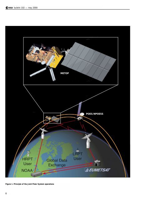
Figure 1. Principle of the Joint Polar System operations<br />
6
metop<br />
Metop: The Space Segment for<br />
Eumetsat’s Polar System<br />
P.G. Edwards<br />
Earth Observation Projects Department, ESA Directorate of Application<br />
Programmes, ESTEC, Noordwijk, The Netherlands<br />
D. Pawlak<br />
Matra Marconi Space*, Toulouse, France<br />
Introduction<br />
Over the years, the need for high-resolution<br />
data sets for a wide range of atmospheric<br />
parameters, with global coverage, has become<br />
more pressing with the increasing sophistication<br />
of the numerical weather-prediction models.<br />
The instrumentation initially embarked on the<br />
Tiros satellites has evolved and now spans the<br />
electromagnetic spectrum from microwaves<br />
through the infrared to the visible, thereby<br />
enabling height profiles of many parameters to<br />
be determined. After decades of such<br />
evolution, the new generation of polar-orbiting<br />
meteorological satellites under development on<br />
both sides of the Atlantic – Metop in Europe<br />
and the National Polar Orbiting Environmental<br />
Satellite System (N<strong>POES</strong>S) in the USA – will<br />
carry considerably larger and more capable<br />
sets of instrumentation.<br />
Metop-1 will be Europe’s first polar-orbiting satellite dedicated to<br />
operational meteorology. As such, it marks the start of our<br />
contribution to balance a long-standing service provided by the United<br />
States from its Tiros, now <strong>POES</strong> (Polar Orbiting Environmental<br />
Satellite), Programme.<br />
The first Tiros satellite was launched 40 years ago and in the<br />
intervening period the US has provided the data from this evolving<br />
series of satellites free of charge to the worldwide meteorological<br />
community. As early as 1967, Europe looked towards balancing this<br />
effort, but initially selected a geostationary satellite mission as the<br />
higher priority. This led to the development of the Meteosat series of<br />
satellites, the first of which was launched in 1977.<br />
* Now Astrium SAS.<br />
The US is currently operating polar-orbiting<br />
meteorological satellites in four Sunsynchronous<br />
orbital planes, for two services: an<br />
early morning and afternoon pair of military<br />
satellites (DMSP) and a mid-morning and<br />
afternoon civil pair operated by NOAA. There<br />
have been many earlier proposals to merge<br />
these services and this convergence is now<br />
underway in conjunction with an agreement<br />
with Europe, represented by Eumetsat, to<br />
participate. The resulting Joint Polar System<br />
(JPS) will maintain three orbital planes, in the<br />
early morning, mid-morning and afternoon. The<br />
Eumetsat Polar System, of which Metop is the<br />
space segment, will provide the mid-morning<br />
service (at a mean local solar time of 09:30),<br />
whilst the US N<strong>POES</strong>S satellites will provide the<br />
other two services.<br />
There will be a transitional phase (termed the<br />
Interim JPS, or IJPS) during which the older<br />
generation of instruments will continue to fly as<br />
the newer instruments are introduced. Thus<br />
Metop-1, -2 and -3 will embark both the older<br />
instruments, provided by NOAA, as well as<br />
more advanced, European, ones. The principle<br />
of the joint systems is shown in Figure 1.<br />
The Metop satellites were originally part of a<br />
much larger satellite concept, called POEM,<br />
which was to have been the successor to ERS-<br />
1 and -2, based on the Columbus Polar<br />
Platform. This very large satellite would have<br />
carried the payloads of both Envisat and Metop<br />
and was imagined to be re-serviceable in-orbit.<br />
At the ESA Ministerial Council in Granada (E) in<br />
1992, this idea was abandoned and Envisat<br />
and Metop were born. Metop is a joint<br />
undertaking by ESA and Eumetsat and forms<br />
part of the Eumetsat Polar System (EPS). In<br />
addition to the space segment (i.e. Metop), the<br />
latter comprises the ground segment, the<br />
launch and various infrastructure elements. The<br />
EPS is at present planned to provide an<br />
operational service for a period of 14 years,<br />
which requires the provision of three Metop<br />
satellites, each with a nominal lifetime of<br />
5 years – an overlap period is assumed<br />
between them for commissioning (Fig. 2).<br />
The EPS, and Metop in particular, have a<br />
number of objectives. This system is the<br />
European contribution is the improved polar-<br />
7
ulletin 102 — may 2000 bull<br />
Figure 2. Timing of the joint<br />
meteorological systems<br />
operations<br />
orbiting meteorological satellite service being<br />
offered to the world’s meteorological<br />
organisations. It also has to satisfy some<br />
specific needs of the European and US<br />
meteorological services; in Europe there is an<br />
increasing trend towards commercialisation of<br />
earth-observation, and hence meteorological,<br />
data, while in the US there are concerns over<br />
the direct broadcasting of data from USprovided<br />
instruments at times of national crisis.<br />
The notable improvements in the service<br />
required of Metop are:<br />
– Provision of new instrumentation (ASCAT,<br />
IASI, GOME-2 and GRAS) compared to the<br />
current generation of NOAA satellites.<br />
– Provision of a low-data-rate digital direct<br />
broadcast service at VHF to replace the<br />
analogue APT (Automatic Picture Transmission)<br />
system, employing data-compression to<br />
ensure high-quality images.<br />
– Continuous on-board recording of the global<br />
data set to be dumped every orbit at a highlatitude<br />
ground station, with a ground segment<br />
sized to provide the global processed data<br />
within 2.25 h of the measurements being<br />
made.<br />
– High pointing and orbital stability to ensure<br />
that data may be geo-located without<br />
reference to ground-control points in imagery.<br />
– A selective encryption system to ensure the<br />
commercial and data-denial needs of Eumetsat<br />
and the US Government, respectively.<br />
The satellite’s main performance figures are<br />
provided in Table 1.<br />
1997 1998 1999 2000 2001 2002 2003 2004 2005 2006 2007 2008 2009 2010 2011 2012 2013 2014 2015 2 016<br />
2017<br />
<strong>METOP</strong>-1<br />
Kick-off<br />
Phase C/D<br />
Launch<br />
Commissioning<br />
Routine Operations<br />
Reviews<br />
PDR<br />
CDR<br />
QR<br />
FAR<br />
<strong>METOP</strong>-2<br />
Phase C/D<br />
Nominal Storage<br />
Destorage<br />
Nominal Launch<br />
Commissioning<br />
Routine Operations<br />
Reviews<br />
FAR<br />
<strong>METOP</strong>-3<br />
Phase C/D<br />
Nominal Storage<br />
Destorage<br />
Nominal Launch<br />
Commissioning<br />
Routine Operations<br />
Reviews<br />
FAR<br />
I JPS/JPS<br />
Satellite Constellation<br />
0530<br />
0730<br />
DMSP<br />
DMSP<br />
N<strong>POES</strong>S<br />
1030<br />
<strong>POES</strong><br />
<strong>METOP</strong><br />
N<strong>POES</strong>S Preparatory Project<br />
NPP<br />
1330<br />
<strong>POES</strong><br />
N<strong>POES</strong>S<br />
8
metop<br />
The payload composition of the first three<br />
Metop satellites may be divided into categories.<br />
In the first group are instruments providing the<br />
transition from the current NOAA satellites:<br />
– Advanced Very High Resolution Radiometer<br />
(AVHRR), an optical/infrared imager with a<br />
spatial resolution of about 1 km over a very<br />
wide swath of some 2000 km.<br />
– High-resolution Infra-Red Sounder (HIRS),<br />
a spectrometer with a relatively coarse<br />
spatial resolution and a mechanical scan over<br />
a wide swath, from which height profiles of<br />
atmospheric pressure and temperature<br />
may be derived – this instrument will not be<br />
embarked on Metop-3, its measurement<br />
functions being taken over by IASI, described<br />
below.<br />
– Advanced Microwave Sounding Unit A<br />
(AMSU-A), a mechanically scanned multichannel<br />
microwave radiometer for the<br />
determination of pressure and temperature<br />
profiles.<br />
– Microwave Humidity Sounder (MHS), a new<br />
instrument, which will fly on the last of the<br />
NOAA satellites, which exactly replaces the<br />
AMSU-B currently provided by the UK<br />
Meteorological Office to NOAA.<br />
– Space Environment Monitor (SEM), which<br />
measures the charged-particle radiation<br />
environment in the vicinity of the satellite.<br />
– Data Collection System (DCS/Argos), a radio<br />
receiving and storage system, which receives<br />
brief telemetry signals from a large global<br />
network of remote stations, most of them<br />
unmanned and mobile. As well as providing<br />
these messages to a central processing and<br />
distribution site, this new version of the<br />
system may also send messages to the<br />
remote terminals.<br />
– Search and Rescue (S&R), a similar system<br />
which immediately rebroadcasts signals<br />
received from emergency transmitters<br />
typically carried on vessels and aircraft,<br />
enabling rescue services over a wide geographical<br />
area to locate the transmitter.<br />
Table 1. Metop main features and performances<br />
Area<br />
Spacecraft orbit:<br />
Launch mass:<br />
On-board propellant:<br />
Spacecraft attitude:<br />
Data handling:<br />
Communications:<br />
On-board power:<br />
Mission lifetime:<br />
Launcher:<br />
Operations:<br />
Performance<br />
- Sun-synchronous near-circular orbit, altitude at ascending node: 796 to 844 km<br />
- Repeat cycle : 5 days (71 orbits)<br />
- Local solar time : 09h30 (descending node)<br />
4174.8 kg<br />
315.7 kg of hydrazine, stored in 4 tanks (including residual)<br />
- Three-axis stabilised through reaction wheels<br />
- Orbit manoeuvres through hydrazine propulsion system<br />
- Pointing knowledge : 0.07° (X-axis), 0.10° (Y-axis), 0.17° (Z-axis)<br />
- Instrument science data acquired as CCSDS packets<br />
- Science data formatting and multiplexing, encryption for selected instruments<br />
- Instrument and housekeeping data storage in a solid-state recorder (24 Gbit)<br />
- Omnidirectional S-band coverage (uplink 2 kbps, downlink 4.096 kbps)<br />
- Instrument global data stream downlinked via X band (70 Mbps data rate)<br />
- Real-time broadcasting of instrument data with HRPT: 3.5 Mbps via L-band for all<br />
instruments, and LRPT: 72 kbps via VHF for selected instruments<br />
- 2210 W from solar panel, average power over one orbit (EOL)<br />
- Five 40 Ah batteries<br />
- 22 - 37.5 V unregulated, and 50 V regulated power lines for SVM/PLM units<br />
- 22 - 37 V unregulated power lines for European instruments<br />
- 28 V regulated power lines for NOAA instruments<br />
5 years<br />
Ariane-5, or Atlas IIAS<br />
- Spacecraft controlled by Eumetsat (Kiruna ground station)<br />
- Instrument X-band data down-linked nominally over 2 ground stations<br />
- Recorded data down-linked not later than one orbit after recording<br />
- Spacecraft autonomy required for 36 h without ground contact<br />
9
ulletin 102 — may 2000 bull<br />
The second group are from the new<br />
generation, and offer improved sensing<br />
capabilities:<br />
– Infrared Atmospheric Sounding Interferometer<br />
(IASI), is an important new development,<br />
which will provide a significant improvement<br />
in the resolution of vertical temperature and<br />
humidity profiles in the atmosphere.<br />
– Advanced Scatterometer (ASCAT), developed<br />
within the framework of the Metop-1<br />
contract, which uses multiple radar beams<br />
to measure the small-scale roughness of the<br />
ocean surface from three directions, over a<br />
wide swath on each sidenof the satellite,<br />
enabling the speed and direction of the wind<br />
to be determined.<br />
– Global Ozone Measurement Experiment 2<br />
(GOME-2), a successor to the ERS-2 GOME-1<br />
with a number of improvements, is a highresolution<br />
visible/ultraviolet spectrometer,<br />
which provides measurements over a wide<br />
swath and wide spectral range such that<br />
ozone profiles and total column amounts of<br />
many other trace gases may be determined.<br />
– GNSS Receiver for Atmospheric Sounding<br />
(GRAS), also developed within the framework<br />
of the MetOp-1 contract, is a geodetic-quality<br />
GPS receiver equipped with three antennas<br />
such that it is able to measure the signals<br />
from GPS satellites in occultation by the<br />
Earth’s atmosphere, enabling temperature<br />
and pressure profiles to be determined.<br />
The main performance parameters of these<br />
instruments are summarised in Table 2.<br />
Table 2. Instrument performances<br />
Instrument Main Characteristics<br />
Main Data Products<br />
Heritage<br />
Notes<br />
AVHRR<br />
HIRS<br />
AMSU-<br />
A1/A2<br />
Six-channel Vis/IR imager (0.6 - 12µm),<br />
swath 2000 km, 1 x 1km resolution<br />
20-channel Optical/IR filter-wheel radiometer;<br />
swath 2000 km; IFOV 17.4 km (nadir)<br />
Step-scan 15 channel total power MW<br />
radiometers for 50 GHz oxygen absorption line;<br />
swath 2000 km; IFOV 30 km (nadir)<br />
Wide-swath vertical sounding plus imagery<br />
temperature profile, humidity profile generated by<br />
Tiros Operational Vertical Sounder (TOVS/ATOVS)<br />
combining data from HIRS, AMSU A1/A2 and<br />
MHS, supported by AVHRR Secondary Products:<br />
sea-surface temperature, cloud fraction/cloud top<br />
height, aerosol, precipitable water, surface<br />
emission, total ozone, sea-ice extent<br />
TIROS/<strong>POES</strong><br />
TIROS/<strong>POES</strong><br />
TIROS/<strong>POES</strong><br />
Disembarked<br />
for <strong>METOP</strong>-3<br />
MHS<br />
Five-channel quasi-optical heterodyne radiometer,<br />
190 GHz for water-vapour absorption line plus<br />
89 GHz for surface emissivity. Swath 2000 km,<br />
IFOV 30 km (nadir)<br />
TIROS/<strong>POES</strong><br />
As AMSU-B<br />
IASI<br />
Fourier-transform spectrometer, 4 IFOV’s of 20 km<br />
at nadir in a square 50 x 50 km. Step-scanned<br />
across track (30 steps), synchronised to AMSU-A.<br />
Integrated (Near-IR) imager for cloud<br />
discrimination. Calibration: blackbody plus two<br />
deep-space views<br />
Water-vapour sounding; NO 2 and CO 2 ;<br />
temperature sounding; surface and cloud<br />
properties. Swath width: 2000 km<br />
Performance: spectral range: 3.62-15.5 µm<br />
in 3 bands; resolution 0.35 cm -1 ; radiometric<br />
accuracy 0.25 - 0.58 K<br />
New<br />
development<br />
Replaces and<br />
supplements<br />
HIRS<br />
ASCAT<br />
C-band radar scatterometer, with three dualswath<br />
antennas (fore/mid/aft). Measurement of<br />
radar backscatter at three different azimuth angles;<br />
fit to a model function to extract wind speed and<br />
direction. Incidence angle range: 25° – 65°<br />
Surface-wind vectors over oceans; additional<br />
products (e.g. sea-ice cover; snow cover;<br />
vegetation density). Swath width: 2 x 500 km;<br />
Quasi-global coverage: 2.5 d.Wind velocity:<br />
± 2ms -1 or 10%; Wind direction: ± 20°<br />
ERS-1/-2<br />
AMI-<br />
Scatterometer<br />
GOME-2<br />
Scanning spectrometer with spectral coverage:<br />
250–790 nm at resolution 0.2–0.4 nm. Double<br />
monochromator design: first stage: quartz prism<br />
with physical separation of four channels; second<br />
stage: blazed gratings in each channel. Detector:<br />
1024 pixel random-access silicon-diode arrays;<br />
Ozone (total column and profiles, stratosphere<br />
and troposphere); NO 2 BrO OClO ClO;<br />
Albedo and aerosol: cloud fraction, cloud-top<br />
altitude, cloud phase.<br />
Swath width: 960 or 1920 km, resolution 80 x 40<br />
or 160 x 40 km<br />
ERS-2<br />
GOME-1<br />
GRAS<br />
GPS satellite receiver measuring changes during<br />
occultation (rising or setting); computation of<br />
bending angle and TEC; retrieval of refractive<br />
index vs altitude profile; fitting data to<br />
stratospheric model for temperature profile.<br />
Bending angle measurement accuracy better than<br />
1 µrad.<br />
Up to 500 occultations/day, with quasi-uniform<br />
geographical distribution<br />
Vertical temperature sounding of ±1 K, with<br />
vertical resolution of 150 m in the troposphere<br />
(5 - 30 km) and 1.5 km in the stratosphere<br />
GPS/MET<br />
10
metop<br />
Aspects of cooperation<br />
The EPS and the Metop Programme are<br />
intensively collaborative in that five major<br />
agencies are extensively involved:<br />
– Eumetsat: System authority, develops<br />
Ground Segment and MHS, co-funds Metop<br />
and IASI, procures launcher, operates system.<br />
– ESA: Co-funds and develops Metop, ASCAT,<br />
GOME-2 and GRAS.<br />
– NOAA: Funds US instruments for Metop;<br />
System authority for <strong>POES</strong> as part of IJPS.<br />
– NASA: Develops/procures AVHRR, HIRS,<br />
AMSU and SEM for Metop.<br />
– CNES: Co-funds and develops IASI; Funds<br />
and develops DCS, SARP.<br />
A special relationship has been developed<br />
between ESA and Eumetsat, governed by a<br />
Figure 3. Cooperation on<br />
Metop<br />
Figure 4. Cooperation<br />
between ESA and Eumetsat<br />
11
ulletin 102 — may 2000 bull<br />
* Now Astrium GmbH<br />
**Now Astrium Ltd.<br />
legal act, the Cooperation Agreement, signed<br />
in December 1999. In this cooperation, a cofunding<br />
arrangement is established for the<br />
Metop industrial contracts, which is managed<br />
by a joint project team called the ‘Single Space<br />
Segment Team (or SSST)’, comprised of staff<br />
from both organisations and located at ESTEC.<br />
The team has an ESA project manager assisted<br />
by a Eumetsat deputy. The respective<br />
responsibilities are shown in Figures 3 and 4.<br />
Industrial architecture<br />
The Prime Contractor for Metop is Matra<br />
Marconi Space France (MMS-F). The contract<br />
includes the three Metop spacecraft and the<br />
ASCAT and GRAS payload instruments. A<br />
separate contract within the Metop Programme<br />
has been placed with Officine Galileo/Alenia<br />
Difesa for the three GOME-2 instruments. All<br />
other payload instruments are provided to the<br />
Metop Programme as customer-furnished<br />
instruments via Eumetsat.<br />
MMS-F is responsible for the execution of all<br />
tasks performed by the industrial team,<br />
including system-level tasks and satellite<br />
assembly, integration and testing, and for the<br />
Service Module (SVM) with its Electrical Ground<br />
Support Equipment (EGSE).<br />
Among the various contractors involved,<br />
– Dornier Satellitensysteme (DSS)* is responsible<br />
for the Payload Module, ASCAT, and GRAS<br />
(with Saab-Ericsson)<br />
– MMS-UK** is responsible for the Service<br />
Module mechanical system, and systemsupport<br />
tasks<br />
– Alenia is responsible for DCS/Search & Rescue<br />
mission integration and accommodation<br />
hardware.<br />
Subcontractors, at unit or subsystem level,<br />
have been selected on the basis of heritage, or<br />
after competition. Figure 5 shows the current<br />
industrial team.<br />
Figure 5. The Metop industrial organisation<br />
12
metop<br />
Context of the mission<br />
The Metop satellite and its payload embody a<br />
great deal of heritage, which has two primary<br />
benefits. The heritage of the satellite (especially<br />
the SVM) and its equipment have enabled<br />
significant cost savings in the development<br />
programme, while the heritage of the payload<br />
and services is an essential element in the<br />
efficient exploitation of the mission data. Almost<br />
all payload elements have direct and<br />
operational precursors, the only exception<br />
being the GRAS instrument, and even this is<br />
the operational follow-on to an in-orbit<br />
experiment. The transitional instruments in the<br />
first group above, commonly called the ATOVS<br />
package, supplemented by the DCS/S+R and<br />
SEM, are directly recurrent from the US<br />
satellites and have a strong heritage both in<br />
terms of hardware provision as well as in the<br />
processing and exploitation of the data.<br />
Amongst these, the MHS instrument is being<br />
developed within the same broad time-frame<br />
as Metop-1, but it is intended to be a direct<br />
replacement for the AMSU-B and, furthermore,<br />
it will fly before Metop on at least one US<br />
satellite.<br />
The ASCAT depends on the same physical<br />
principle as the scatterometers on ERS-1 and<br />
ERS-2, and the higher level processing of the<br />
data is equivalent. Hence it may be rapidly<br />
adopted as an operational instrument, as the<br />
ERS-2 instrument is today. However, it has two<br />
swaths compared to the one of ERS and also<br />
uses a different radar technique, such that the<br />
data pre-processing needs to be newly<br />
developed. The GOME-2 is also strongly<br />
related to the equivalent instrument on ERS-2,<br />
again leading to many advantages in terms of<br />
procurement, development of operational data<br />
processors, and existing user-experience in the<br />
data exploitation.<br />
Figure 6. The Service Module’s heritage<br />
13
ulletin 102 — may 2000 bull<br />
MMS has more than twenty years of<br />
experience in the development of low-Earthorbit<br />
service modules which is of direct benefit<br />
for Metop. Regular upgrades to the Spot-1<br />
concept have been performed to meet higher<br />
performance requirements and to maintain<br />
up-to-date avionics and technologies. A<br />
cumulated 46 year lifetime in orbit has been<br />
achieved today with 8 satellites (ERS-1 and 2,<br />
Spot-1, 2, 3 and 4, and Helios-1A and 1B)<br />
using the same SVM concept (Fig. 6). The<br />
Spot-1 SVM completed its 14th year of<br />
operation last year. ERS-1 operated very<br />
successfully for almost 9 years.<br />
Overall architecture of the satellite<br />
In order to accommodate the mission, and to<br />
ease the development as well as the verification<br />
process, the satellite’s overall design is based<br />
on a modular approach, which relies upon two<br />
largely independent modules, the Payload<br />
Module and the Service Module. Figure 7 shows<br />
the Metop in-flight configuration.<br />
The Payload Module (PLM)<br />
The PLM provides the main supporting<br />
structure for both the payload instruments and<br />
the payload support systems. Instrument<br />
sensors and antennas are mounted on the<br />
Figure 7. Metop’s in-flight<br />
configuration<br />
14
metop<br />
external panels, while most of the electronics<br />
units are accommodated inside the PLM.<br />
The accommodation of a large complement of<br />
instruments is a significant design driver for<br />
the overall PLM configuration, with many<br />
constraints originating from instrument fields of<br />
view, antenna patterns, and thermal radiators<br />
having to be accounted for. In addition to the<br />
instrument units, the PLM also houses all of the<br />
avionics necessary to ensure:<br />
– power regulation for the US instruments: as<br />
these instruments need a 28 V regulated<br />
power bus not available from the SVM; a<br />
dedicated power control unit is provided by<br />
the PLM<br />
– power distribution: each unit or instrument is<br />
powered through a switchable and protected<br />
line, provided by specific PLM units<br />
– command and control: a dedicated data bus,<br />
based on the European On-Board Data<br />
Handling Standard (OBDH), is used by the<br />
PLM. The Payload Module Computer (PMC)<br />
receives commands from the SVM and<br />
interfaces with the European instruments<br />
ICUs (Instrument Control Units) and MPU<br />
(MHS PLM adaptation Unit), as well as with a<br />
specific PLM unit for the US instruments<br />
– handling of scientific data consisting of<br />
acquisition, formatting, encryption, storage,<br />
and transmission to ground of CCDS<br />
packetised data through the HRPT (High-<br />
Rate Picture Transmission), LRPT (Low-Rate<br />
Picture Transmission), and X-band links.<br />
The Service Module (SVM)<br />
The SVM provides all the standard service<br />
functions, like:<br />
– attitude and orbit control, to maintain<br />
accurate Earth-pointing during the various<br />
operational modes, and to perform orbit<br />
acquisition and maintenance<br />
– propulsion, for orbit and dedicated manoeuvres,<br />
as well as propellant storage<br />
– electrical power generation, through the solar<br />
array, storage, conditioning, and overall<br />
distribution<br />
– distribution of on-ground and on-board<br />
generated commands, and collection of housekeeping<br />
telemetry data for transmission to<br />
ground through the S-band link<br />
– central on-board software for telemetry<br />
generation, telecommand processing, and<br />
various application functions (e.g. thermal<br />
control, on-board surveillance, automatic<br />
command sequencing).<br />
The mechanical subsystem is derived from the<br />
Envisat Service Module. It is a box-shaped<br />
structure that interfaces with both the launch<br />
vehicle and the PLM. Interfaces between the<br />
two modules have been standardised as much<br />
as possible, and kept to a minimum. Thermal<br />
exchanges between the two modules are very<br />
limited, mechanical interfaces basically consist<br />
of the two modules connection, electrical<br />
interfaces are limited to power and OBDH bus,<br />
plus solar-array deployment and pyrotechnics<br />
needs, data exchanges use telemetry and<br />
telecomand packets.<br />
The satellite overall dimensions (in metres) are<br />
close to 6.3 (high) by 3.4 x 3.4 (transverse<br />
section) in launch configuration, and 17.6 x 6.6<br />
x 5.0, after solar-array and antenna deployment.<br />
Electrical architecture<br />
Modularity and standardisation are the main<br />
design drivers for the electrical architecture<br />
(Fig. 8). The design offers simple interfaces, and<br />
makes use of existing hardware developed in<br />
the frames of Spot-5 for the SVM and Envisat<br />
for the PLM.<br />
Power generation, storage and distribution<br />
Electrical power is generated by an eight-panel<br />
solar array derived from Envisat. Energy<br />
storage is provided by five batteries, which<br />
allow operation in the launch and early orbit<br />
phase (LEOP), eclipse and contingency modes.<br />
The primary power bus is an unregulated bus,<br />
which is distributed to both the SVM and PLM<br />
units. The 28 V power regulation needed by the<br />
US instruments is performed by a dedicated<br />
PLM unit (PCU).<br />
Command and control<br />
The command and control functions are<br />
distributed throughout the spacecraft, and also<br />
have to accommodate a range of interface<br />
requirements from the heritage instruments.<br />
The Metop-specific equipment and instruments<br />
use the European OBDH interfaces, while the<br />
MHS uses the MIL-STD-1553 interface. Both of<br />
these are high-level command and control<br />
interfaces allowing for intelligence within the<br />
instruments. The heritage instruments from<br />
NOAA have a much simpler interface with<br />
distributed signal lines.<br />
The distributed command and control<br />
architecture features the following elements:<br />
– The primary spacecraft computer is within<br />
the SVM and is responsible for the interface<br />
to the ground segment and control of the<br />
equipment in the SVM and for the overall<br />
security of the mission.<br />
– Command and control of the payload is<br />
performed by the PLM Computer (PMC),<br />
which is connected to the SVM computer via<br />
the SVM OBDH bus. This computer controls<br />
a specific OBDH bus within the PLM.<br />
15
ulletin 102 — may 2000 bull<br />
Figure 8. Metop’s electrical<br />
architecture<br />
16<br />
– The ‘European’ instruments (ASCAT, GRAS,<br />
GOME, IASI) each include an intelligent<br />
Instrument Control Unit (ICU) which<br />
communicates with the PMC.<br />
– The MHS communicates via a specific<br />
adaptation unit, MPU, or MHS Protocol Unit,<br />
which performs the translation between the<br />
MHS MIL-STD 1553 bus and the PLM<br />
OBDH. The MPU also provides the sciencedata<br />
interface.<br />
– The NOAA Interface Unit (NIU) emulates the<br />
Tiros-spacecraft-type interfaces required by<br />
the NOAA instruments. It includes its own<br />
ICU, which performs the command and<br />
control function as well as packaging the<br />
NOAA instrument data into CCSDS<br />
packets. It also performs the AVHRR data<br />
compression.<br />
Payload data handling and transmission<br />
The science data from the payload is provided<br />
in the form of CCSDS packets at a wide range<br />
of data rates, ranging from 1.5 Mbps for IASI to<br />
160 bps for SEM. The PMC also provides<br />
some additional packets required for data<br />
exploitation:<br />
– Position and time data derived from the<br />
GRAS.<br />
– A copy of the full spacecraft housekeeping<br />
telemetry.<br />
– A text ‘administration message’ which is<br />
uplinked and stored on board, providing the<br />
facility to broadcast information to remote<br />
users.<br />
All of these data streams are multiplexed and<br />
provided on three channels going to the onboard<br />
recorder, the HRPT, and LRPT directbroadcast<br />
subsystems. Encryption is possible<br />
for the direct-broadcast services. Only a subset<br />
of the packets is provided to the LRPT.<br />
The Solid-State Recorder is based on the<br />
Cluster and Envisat design, and has a capacity<br />
of 24 GB at end-of-life. This is sufficient for<br />
slightly more than one full orbit of data.The<br />
X-band subsystem provides a direct 70 Mbps<br />
transmission link to ground during visibility<br />
periods, dumping the data stored during the<br />
previous orbit to ground.<br />
Telemetry, tracking and command<br />
Two antennas allowing omni-directional coverage<br />
interface with the S-band transponder by<br />
means of a 3 dB hybrid coupler. Each<br />
transponder consists of a diplexer, a receiver<br />
and a transmitter.<br />
Attitude and orbit control<br />
The AOCS architecture is based around three<br />
units performing the interface between the<br />
SVM OBDH bus and the sensors and<br />
actuators. A first unit (T4S) interfaces with the<br />
Earth and Sun sensors, and with the gyros; the<br />
EAIM provides the interface with the reaction<br />
wheels and the magnetotorquers; the EPRM<br />
ensures the necessary command and acquisition<br />
capability for the propulsion subsystem, and<br />
also interfaces with the solar-array drive<br />
mechanism.
metop<br />
Figure 8: Metop’s encryption<br />
scheme<br />
In all nominal modes, the AOCS software is<br />
part of the SVM central flight software. In Sunpointed<br />
safe mode, the AOCS function is<br />
autonomously ensured inside the T4S unit by<br />
the survival electronics, which feature an<br />
independent computer.<br />
Mission-specific features<br />
High-Rate and Low-Rate Picture Transmission<br />
(HRPT/LRPT)<br />
The Metop satellite continuously records its<br />
data on-board, but it also provides a<br />
continuous direct data-broadcast service, with<br />
two simultaneous signals. The HRPT service<br />
operates with a microwave link at L-band with<br />
the full data content as recorded on-board (at<br />
3.5 Mbps). This service is very similar to the<br />
existing service from the NOAA satellites and<br />
enables regional meteorological organisations<br />
to receive all data relevant to their area in real<br />
time. The LRPT service is more innovative and<br />
replaces the APT service provided today by the<br />
NOAA satellites. It is an analogue broadcast at<br />
VHF, providing low-resolution AVHRR images<br />
to several thousands of users equipped with<br />
small, inexpensive receivers. This system has<br />
enabled local cloud patterns to be displayed<br />
easily, for example in schools. The digital LRPT<br />
service retains the VHF frequency and<br />
bandwidth of the APT service, but provides<br />
three channels of AVHRR data at the full<br />
instrument spatial and radiometric resolution,<br />
through the use of a modified JPEG<br />
compression scheme. To minimise the effect of<br />
ionospheric scintillation at VHF, a powerful<br />
interleaving and modulation scheme has been<br />
developed which will make the system strongly<br />
resistant to data drop-outs, which in the<br />
analogue system would result in missing scan<br />
lines.<br />
Encryption<br />
In order to limit data access, Metop provides<br />
facilities to encrypt data for LRPT and HRPT<br />
channels. The encryption scheme is selective<br />
on virtual channels and users. Also, there are<br />
separate keys for LRPT and HRPT.<br />
The encryption is based on the principle shown<br />
in Figure 9. The encryption itself is performed<br />
by doing an exclusive OR between each VCDU<br />
Data Unit zone and a pseudo-noise pattern. As<br />
this operation is fully reversible, the data at<br />
ground are decrypted by using the same<br />
pseudo-noise pattern with an exclusive OR<br />
with data. The pseudo-noise pattern that is the<br />
basis for the encryption is created from:<br />
– The secret Master Satellite Key (MSK), which<br />
is stored on board and cannot be transmitted<br />
to ground via telemetry.<br />
– The Public Satellite Keys, which can be<br />
uploaded from the ground periodically to<br />
ensure sufficient secrecy and to control data<br />
access. On Metop, there is a table of 64<br />
different possibilities. For each encryption<br />
process, there is a suitable telecommand in<br />
order to select the appropriate key.<br />
These two keys are processed through a Data<br />
Encryption Standard (DES) algorithm (decryption<br />
part) in order to get the Message Key.<br />
Compression<br />
The AVHRR scanning mirror rotates at 360<br />
rpm, producing five lines (one per channel) of<br />
Earth-view samples every 1/6 sec. The<br />
samples are 10 bits wide and each Earth-view<br />
line contains 2048 pixels (1 pixel is about 1 km),<br />
which means a data rate of 2048 (samples) x 3<br />
(spectral bands) x 6 (lines per second) x 10 (bits<br />
per sample) = 369 kbps. As the allocated data<br />
rate for AVHRR/LRPT is 40 kbps, global factor-<br />
10 data compression is required. The following<br />
convention has been adopted for the<br />
compression (Fig. 10):<br />
– The AVHRR/LRPT will contains only three<br />
spectral compressed images and one<br />
calibration data packet. Five spectral channels<br />
are inside HRPT.<br />
17
ulletin 102 — may 2000 bull<br />
Figure 10. Metop’s<br />
compression scheme:<br />
AVHRR data<br />
2048 pixels<br />
line n<br />
hdr<br />
1 strip compressed data<br />
1 strip<br />
8/6 sec<br />
8 pixels x 8 lines = 1 block<br />
Compression<br />
line n+7<br />
scan<br />
hdr<br />
seg 1<br />
seg n<br />
1 segment = 1 area with<br />
constant Q factor<br />
seg hdr MCU 1<br />
MCU m<br />
1 MCU = 1 block compressed data<br />
1 AVHRR strip (per channel)<br />
2200 km x9km<br />
Compression<br />
1 CCSDS packet : 256 MCU<br />
(1MCU=9kmx9kmcompressed data)<br />
Table 3. Metop’s data interface with ground<br />
Data Description Frequency Domain Useful Bit Rate<br />
TT&C uplink S-band 2053.4 MHz 2000 bps in NRZ/PSK/PM<br />
TT&C downlink S band 2230 MHz 4096 bps in SP-L/PSK/PM<br />
Global Data Stream X-band 7750-7900 MHz 70 Mbps in QPSK<br />
downlink<br />
LRPT downlink VHF 137.1 MHz 72 kbps in QPSK<br />
HRPT downlink L-band 1701.3 MHz 3.5 Mbps in QPSK<br />
– The compression is applied to the 10-bit<br />
data sample words.<br />
– The compression algorithm is a modified<br />
JPEG to accommodate a fixed compression<br />
rate and a continuous instrument data rate.<br />
An AVHRR image can be divided into strips<br />
(8 lines). The compressed part of the strip will be<br />
transmitted in the user data field of one CCSDS<br />
packet. The strips are divided into segments.<br />
Inside a segment, a constant Q factor is<br />
applied. Finally, each segment is divided into<br />
blocks of 8 pixels x 8 lines. A compressed block<br />
is called a Minimum Coded Unit (MCU). There<br />
will be four packets (three channels and one<br />
calibration) every 8/6 seconds (1 strip lasts 8/6<br />
sec). The global number of MCUs is 2048/8 =<br />
256. The number of segments can be<br />
programmed from the ground, albeit with a<br />
potential impact on image quality since a<br />
constant Q factor is applied on one segment.<br />
and X-band (global data dump). In addition to<br />
these links, Metop provides an Advanced DCS<br />
(Argos) service and a Search & Rescue (SARR/<br />
SARP) service with the following frequencies:<br />
– A-DCS data reception at 401.65 MHz<br />
– A-DCS data transmission at 466 MHz<br />
– SARR beacon-signal reception at 121.5,<br />
243 and 406.05 MHz<br />
– SARP-2 data reception at 406.05 MHz<br />
(common with SARR)<br />
– SARR data transmission at 1544.5 GHz.<br />
These links are performed by means of an<br />
antenna farm comprised of the following<br />
elements:<br />
– X-band transmit antenna<br />
– S-band TT&C receive/transmit antenna<br />
– LRPT VHF transmit antenna<br />
– HRPT L-band transmit antenna<br />
– CRA: Combined Receive Antenna (uplink)<br />
– SLA: Search and Rescue L-band transmit<br />
antenna<br />
– DTA: DCS transmit antenna.<br />
One major consequence of these various<br />
space-to-ground links, combined with<br />
numerous RF instruments (AMSU A1, AMSU<br />
A2, MHS, GRAS, ASCAT), is the fact that<br />
ensuring RF compatibility within the satellite is a<br />
challenging design requirement leading to<br />
an extensive test campaign and a dedicated<br />
development approach. r<br />
Communications links<br />
The satellite provides data transmission to and<br />
from the ground with the characteristics<br />
defined in Table 3, and as described previously,<br />
in S-band (TT&C), L-band (HRPT), VHF (LRPT)<br />
18