Turbo Air® 3000 Centrifugal Compressor - Nessco.no
Turbo Air® 3000 Centrifugal Compressor - Nessco.no
Turbo Air® 3000 Centrifugal Compressor - Nessco.no

Create successful ePaper yourself
Turn your PDF publications into a flip-book with our unique Google optimized e-Paper software.
C o m p r e s s i o n S y s t e m s<br />
<strong>Turbo</strong> Air ® <strong>3000</strong><br />
<strong>Centrifugal</strong> <strong>Compressor</strong><br />
Oil-Free Air
C o m p r e s s i o n S y s t e m s<br />
Control Systems<br />
Cameron's Compression Systems can provide the right<br />
control system engineered for your applications.<br />
Maestro tm Suite of Controls<br />
Maestro is the new suite of control systems from<br />
Cameron. The Maestro suite contains a model that<br />
is sure to be in tune with your needs.<br />
Maestro tm Legend<br />
• Provides comprehensive control of your centrifugal<br />
compressor and can be configured to coordinate the<br />
operation of multiple compressors<br />
• Maintain plant pressure to within 0.07– 0.14 bar/1–2<br />
PSI, which allows overall pressure reduction to improve<br />
efficiency and reduce air leakage losses, saving energy<br />
dollars<br />
Maestro tm PLC<br />
• Utilizes an open architecture Allen Bradley PLC,<br />
which enables you to use off-the-shelf components that<br />
match other panels in your plant<br />
• Available in three control methods: Constant<br />
Pressure, Auto/Dual, and Mass Flow<br />
Maestro tm EZ<br />
• An eco<strong>no</strong>mical control system for basic<br />
compressor operation<br />
• A standardized PLC solution with broad built-in<br />
capabilities designed for simplified use
Why Compression Systems?<br />
Oil-Free Air<br />
• Prevents oil contamination of<br />
your system<br />
• Removes the potential for<br />
compressed air pipeline fires<br />
caused by oil carryover<br />
• Eliminates costly waste disposal<br />
problems associated with oil-laden<br />
condensate<br />
• Eliminates the expense and<br />
associated maintenance<br />
requirements of oil removal filters,<br />
since <strong>no</strong> oil enters the compressed<br />
air stream in the compressor<br />
Simple Installation<br />
• Complete package including<br />
aftercooler, controls, motor, and<br />
lubrication system<br />
• Minimum number of<br />
external connections<br />
• Compact design requires<br />
minimum floor space<br />
• Meets OSHA’s sound level requirements<br />
without sound enclosure<br />
Easy Operation<br />
• The new Maestro Suite of<br />
Controls offers three models,<br />
one of which is sure to be in<br />
tune with the needs of your<br />
application. Whichever model<br />
you choose, Maestro provides<br />
the compressor industry's most<br />
advanced control system to<br />
improve efficiency and save<br />
energy dollars<br />
• Easy-to-use, totally<br />
automatic operation<br />
High Reliability<br />
• Thrust loads absorbed at low speed<br />
• No wearing parts<br />
• Non-contact air and oil seals<br />
• Stainless steel compression elements<br />
• Conservative high-quality<br />
gear design<br />
• Unlimited life pinion bearing design<br />
Easy Maintenance<br />
• No wearing parts requiring periodic<br />
changes or replacement in the<br />
compression elements<br />
• No oil removal filters to clean<br />
• Accessible horizontally-split gear<br />
box for quick inspection<br />
• Intercooler and aftercooler bundles<br />
are easily removed for cleaning<br />
• Water in the tube design<br />
intercooler and aftercooler<br />
allows for simple mechanical<br />
cleaning<br />
• Maintenance free dry coupling<br />
Lowest Cost Operation<br />
• True unloading capability. Energy<br />
savings and increased uptime<br />
translate to minimum operating<br />
life cycle costs<br />
• Excellent part-load efficiencies for<br />
any operating load<br />
• No sliding or rubbing parts in the<br />
compression process causing wear<br />
and thereby efficiency loss<br />
Lowest <strong>Compressor</strong> Operating Life Cycle Cost<br />
Over time, the energy required to<br />
power a compressed air system is<br />
the largest cost associated with a<br />
compressor, particularly in today’s<br />
fluctuating energy markets. That is<br />
why, to determine the best return on<br />
your investment over the life cycle<br />
of a compressor, it is important to<br />
consider the initial investment, energy<br />
consumption and maintenance.<br />
As the chart demonstrates,<br />
the <strong>Turbo</strong> Air ® <strong>3000</strong> provides the<br />
lowest total life cycle cost of any<br />
compressor, including dry screw,<br />
variable speed drive (VSD) screw, and<br />
other centrifugal compressors. Keep<br />
in mind, VSD manufacturers often<br />
tout energy savings with unrealistic<br />
turndowns, in excess of 50%. At<br />
this point, you would be better off<br />
purchasing a smaller compressor<br />
and reducing your initial investment.<br />
Also, as screw compressors wear out,<br />
energy consumption increases.<br />
Compared to other machines of<br />
similar capacity, <strong>Turbo</strong> Air ® <strong>3000</strong><br />
compressors are the most efficient<br />
oil-free compressors at full load,<br />
part load, and <strong>no</strong> load.<br />
120%<br />
100%<br />
80%<br />
60%<br />
40%<br />
20%<br />
0%<br />
ENERGY<br />
MAINTENANCE<br />
INVESTMENT<br />
The power savings delivered can<br />
significantly speed up the payback<br />
on your initial investment and the<br />
savings continue to build the more<br />
you use the <strong>Turbo</strong> Air ® <strong>3000</strong>.<br />
LIFE CYCLE COST COMPARISON<br />
OVER 10 YEARS OPERATION 80% LOADED<br />
COMPRESSION<br />
VSD SCREW<br />
SYSTEMS<br />
OTHER<br />
CENTRIFUGAL<br />
DRY SCREW
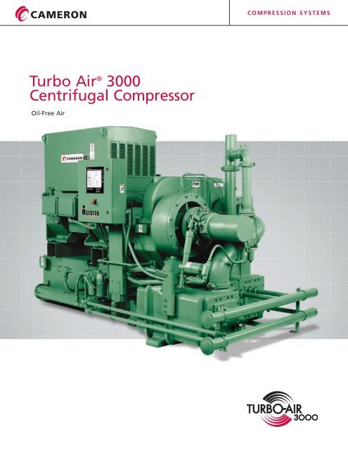
<strong>Turbo</strong> Air ® <strong>3000</strong> <strong>Centrifugal</strong> <strong>Compressor</strong>s<br />
The most efficient<br />
package available –<br />
Easy, low cost installation and<br />
operation. Includes control center,<br />
built-in aftercooler and packaged<br />
check valve.<br />
Basic Installation Arrangement<br />
<strong>Compressor</strong> Motor Sizes Available:<br />
300-600 kW / 400-800 HP<br />
<strong>Compressor</strong> Discharge Pressure Ranges:<br />
3.5-10 BAR, G / 50-150 psig<br />
<strong>Compressor</strong> Flow Ranges:<br />
57-113 m 3 /min / 2,000-4,000 CFM<br />
<strong>Compressor</strong> Weight:<br />
5,443 kg / 12,000 lbs Typical<br />
(Motor Dependent)<br />
3391 mm/133.5 inches 1821 mm/71.70 inches<br />
1981 mm/78 inches<br />
Typical Performance Curve for 522 Kw/8.6 BAR, G – 700 HP/125 PSIG<br />
12.0<br />
BAR, G<br />
10.0<br />
8.0<br />
6.0<br />
31%<br />
Turndown<br />
Impellers – Advanced design combines the best features<br />
of a semi-radial backward leaning impeller.<br />
4.0<br />
2.0<br />
550.<br />
500.<br />
kW<br />
450.<br />
400.<br />
Vaned Diffusers – Matching diffusers for superior efficiency.<br />
350.<br />
70. 80. 90. 100. 110.<br />
m 3 /min<br />
Typical P & ID<br />
6/8" Pipe<br />
Control<br />
Center<br />
M<br />
SD<br />
VI<br />
C/P<br />
VE<br />
Stage 1 Stage 2<br />
TE<br />
SD<br />
TI<br />
C/P<br />
Stage 3<br />
PI<br />
C/P<br />
PE<br />
Discharge<br />
Pressure<br />
Connection<br />
4" Pipe<br />
Inlet<br />
Guide<br />
Vane<br />
1st Stage<br />
Intercooler<br />
2nd Stage<br />
Intercooler<br />
Aftercooler<br />
Bypass Valve<br />
M<br />
PO<br />
Condensate Drain<br />
1/2" NPT<br />
Condensate Drain<br />
1/2" NPT<br />
Condensate Drain<br />
1/2" NPT<br />
To<br />
Control<br />
Center
C o m p r e s s i o n S y s t e m s<br />
Lubrication System<br />
Self contained, low pressure<br />
lubrication system.<br />
Intercoolers/Aftercoolers – Water-in-tube<br />
intercooler and aftercooler bundles slide out<br />
for easy inspection and cleaning.<br />
3/8"<br />
NPTM<br />
L I<br />
Lube Oil<br />
Reservoir<br />
Check<br />
Valve<br />
Bleed<br />
Valve<br />
Main<br />
Pump<br />
Stage 3<br />
Pinion<br />
Stage 1<br />
Pinion<br />
Stage 1<br />
Pinion<br />
VG<br />
Bullgear<br />
Bearings<br />
Maestro TM controls packaged<br />
as standard.<br />
PVC<br />
3/4"<br />
Drain<br />
Plugged<br />
Auxiliary<br />
Oil Pump<br />
Regulator<br />
Check Valve<br />
TE<br />
PE<br />
PE<br />
O/C<br />
TVC<br />
Filter<br />
Horizontally Split Gear Box – Allows for easy<br />
access when the customer’s maintenance<br />
policy requires periodic inspection.<br />
Coolant Lines<br />
(Optional Manifold)<br />
Oil Seal<br />
Air Seal<br />
Oil Supply<br />
Bearing<br />
Viscous Damper<br />
Housing<br />
Superior Pinion Bearing Design –<br />
For unlimited life and operation at<br />
any load.<br />
Seals – Non-contact, <strong>no</strong>n-wearing labyrinth<br />
air and oil seals. No buffer air required for<br />
oil-free air. Eliminates the need for periodic<br />
replacement of carbon seals.<br />
Variable Inlet Guide Vanes – Variable inlet<br />
guide vanes can offer power savings of up<br />
to 9%. Inlet vanes impart a whirling motion<br />
to the inlet air flow in the same direction as<br />
the impeller operation, reducing the work<br />
input. Net power savings at reduced flow or<br />
on days colder than the design temperature.<br />
Inlet vanes are positioned close to the<br />
impeller to achieve maximum benefit.
C o m p r e s s i o n S y s t e m s<br />
Locations to Serve You Worldwide<br />
Headquarters<br />
16250 Port Northwest Drive<br />
Houston, TX 77041 USA<br />
Tel 713.354.1900<br />
Fax 713.354.1923<br />
manufacturing & Engineering<br />
Center of excellence<br />
3101 Broadway<br />
P.O. Box 209<br />
Buffalo, New York<br />
14225-0209 USA<br />
Toll Free: 877.805.7911<br />
Tel 716.896.6600<br />
Fax 716.896.1233<br />
www.c-a-m.com<br />
Sales Offices<br />
North America<br />
3070 Bristol Pike Suite 106<br />
Bensalem, PA 19020 USA<br />
Tel 215.245.9150<br />
Fax 215.245.9170<br />
Europe/Middle East/Africa<br />
Via Cantu´ 8/10<br />
20092, Cinisello Balsamo (MI), Italy<br />
Tel 39.02.6129.2010<br />
Fax 39.02.6129.4240<br />
Mexico<br />
Homero 1804, Desp. 403<br />
Col. Chapultepec Morales<br />
Deleg Miguel Hidalgo<br />
11510 Mexico, D.F.<br />
Tel 5255.5395.1114<br />
Fax 5255.5395.4162<br />
United Arab Emirates<br />
Dubai World Trade Center<br />
P.O. Box 9213<br />
Dubai<br />
Tel 971.4.3313160<br />
Fax 971.4.3314417<br />
Asia Pacific<br />
No. 2 Gul Circle<br />
Jurong Industrial Town<br />
Singapore 629560<br />
Tel 656.863.3631<br />
Fax 656.862.1662<br />
Tower A, Room 1701-1703<br />
Chengjian Plaza<br />
No. 18 Beitaipingzhuang<br />
Haidian District<br />
Beijing 100088, China<br />
Tel 86.10.82255700<br />
Fax 86.10.82255711<br />
South America<br />
Alameda Santos, 455<br />
Conj. 212 – Paraiso<br />
CEP 01419-0000<br />
Sao Paulo, Brazil<br />
Tel 55.11.3284.1164<br />
Fax 55.11.3284.3872<br />
Cameron's Compression Systems strives for continuous improvement in all aspects<br />
of our business. Cameron's Compression Systems reserves the right to modify<br />
designs and specifications without <strong>no</strong>tice or obligation. Nothing contained in this<br />
brochure is intended to extend any type of warranty, expressed or implied.<br />
©2007 Cameron International Corporation | Compression Systems Division | 5/07<br />
Printed in USA