âScrollâ Water-Cooled Packaged Unit - McQuay
âScrollâ Water-Cooled Packaged Unit - McQuay
âScrollâ Water-Cooled Packaged Unit - McQuay

Create successful ePaper yourself
Turn your PDF publications into a flip-book with our unique Google optimized e-Paper software.
CMWCP - 2004<br />
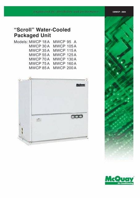
“Scroll” <strong>Water</strong>-<strong>Cooled</strong><br />
<strong>Packaged</strong> <strong>Unit</strong><br />
Models: MWCP 18 A<br />
MWCP 30 A<br />
MWCP 35 A<br />
MWCP 55 A<br />
MWCP 70 A<br />
MWCP 75 A<br />
MWCP 85 A<br />
MWCP 95 A<br />
MWCP 105 A<br />
MWCP 115 A<br />
MWCP 125 A<br />
MWCP 130 A<br />
MWCP 160 A<br />
MWCP 200 A
Contents<br />
Description ....................................................................................................................2<br />
Specification ............................................................................................................. 3- 7<br />
Performance Table ........................................................................................................ 8<br />
Outlines and Dimensions ...................................................................................... 9 - 12<br />
Installation ............................................................................................................ 13 - 14<br />
Piping Connections ............................................................................................. 15 - 16<br />
Duct Connections ....................................................................................................... 17<br />
Operation .....................................................................................................................18<br />
Electrical Data ............................................................................................................. 19<br />
Electronic Controller .......................................................................................... 20 – 21<br />
Wiring Diagrams ................................................................................................... 22 - 31<br />
Fan Curve ............................................................................................................. 32 – 36<br />
Maintenance................................................................................................................. 37<br />
Trouble Shooting......................................................................................................... 38<br />
Note: Installation and maintenance are to be performed only by qualified personnel who are<br />
familiar with local codes and regulations, and experienced with this type of equipment,<br />
Caution: Sharp edges and coil surfaces are a potential injury hazard. Avoid contact with them.<br />
Warning: Moving machinery and electrical power hazards. May cause severe personal injury or death.<br />
Disconnect and lock off power before servicing equipment.<br />
"<strong>McQuay</strong>" is a registered trademark of <strong>McQuay</strong> International. All rights reserved throughout the world.<br />
©2003 <strong>McQuay</strong> International<br />
"Bulletin illustrations cover the general appearance of <strong>McQuay</strong> International products at the time of publication<br />
and we reserve the right to make changes in design and construction at any time without notice."<br />
Page 1
Description<br />
The <strong>McQuay</strong> “SCROLL” MWCP water-cooled packaged units are designed for duct type air-conditioning<br />
system in commercial and industrial application. An optional plenum is available for MWCP18A-MWCP70A,<br />
for free standing applications. The MWCP water-cooled packaged unit has single or multiple hermetic<br />
compressors with independent refrigerant circuits. Each refrigerant circuit consists of a high efficiency<br />
condenser, a sealed strainer, and capillary tubes. Every <strong>McQuay</strong> MWCP unit has been leak tested,<br />
evacuated and fully charged with refrigerant R22 at the factory.<br />
High Efficiency Hermetic Compliant Scroll Compressor (MWCP18A~MWCP125A)<br />
• Quiet operation.<br />
• Unmatched reliability with 70% fewer moving parts than comparably sized reciprocating compressors.<br />
• Greater capability at handling liquid and debris in the system.<br />
• High efficiency performance.<br />
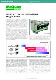
Enhanced Copper Tubes Condenser (MWCP70A~200A)<br />
Extra-high efficiency is attained by special designed shell-and-tube condenser with “T” groove copper tube<br />
surfaces for superior refrigerant-water heat transfer.<br />
Anti-Corrosion <strong>Unit</strong> Casing<br />
<strong>Unit</strong> casing is constructed of electro-galvanized steel sheet. Casing surface is finished with epoxy polyester<br />
powder coating. Therefore, units are suitable for both commercial and industrial application.<br />
Whisper- Quiet Operation<br />
Each unit is divided into separate compartments such that compressor noise is kept away from the supply air<br />
stream. Internal insulation of 1/2 inch thick fiberglass and double blowers design (only for MWCP85A~200A)<br />
further reduce noise level.<br />
Quality Assurance<br />
Each unit is leak-tested, evacuated, fully charged with refrigerant and run tested in <strong>McQuay</strong>’s ISO9001<br />
certified factory.<br />
Page 2
Specifications<br />
Specifications for 50Hz<br />
MODEL MWCP18A MWCP30A MWCP35A MWCP55A MWCP70A<br />
TOTAL COOLING CAPACITY<br />
kcal/h 14620 22360 30100 45580 60370<br />
Btu/h 58100 88800 119600 181000 240000<br />
W 17000 26000 35000 53000 70200<br />
ELECTRICAL HEATER W 6000 9000 12000 21000 27000<br />
TOTAL POWER INPUT<br />
COOLING kW 4.34 (4.16) 7.1 ( 7.1) 9.7 (9) 14.29 (13.49) 19 (18)<br />
HEATING kW 6.55 (6.37) 10.1 (10.1) 14.2 (13.5) 24 (23.4) 31 (30)<br />
POWER SOURCE V/Ph/Hz 380-415V / 3 / 50Hz<br />
CAPACITY STEPS % 0 - 100 0 - 100 0 - 100 0-33-67-100 0 - 50 - 100<br />
REFRIGERANT<br />
REFRIGERANT CHARGE kg 1.45 2.5 3.1 1.7 + 3.3 3.7 x 2<br />
REFRIGERANT CONTROL<br />
EVAPORATOR<br />
FAN<br />
AIR FLOW<br />
TYPE<br />
R22<br />
CAPILLARY TUBES<br />
ALUMINIUM SLIT FINS / COPPER TUBES<br />
ROWS 3 3 3 3 3<br />
FPI 12 12 12 13 13<br />
TYPE<br />
DRIVE<br />
EXTERNAL STATIC PRESSURE<br />
CONDENSER<br />
DIMENSIONS<br />
DOUBLE SUCTION MULTI-BLADE CENTRIFUGAL TYPE<br />
BELT DRIVE<br />
MOTOR OUTPUT kW 0.55 (0.37) 1.1 2.2 (1.5) 3 (2.2) 4 (3)<br />
TYPE<br />
m³/h 2880 4200 5400 8100 10800<br />
CFM 1694 2470 3176 4765 6353<br />
inWg 0.31 (0) 0.39 (0) 0.39 (0) 0.59 (0) 0.59 (0)<br />
Pa 80 (0) 100 (0) 100 (0) 150 (0) 150 (0)<br />
TUBE IN TUBE<br />
WATER FLOW m³/h 3.4 5.5 8.5 11 12.6<br />
WATER HEADLOSS mH 2 O 3.5 3.7 3.8 4 4.2<br />
LENGTH mm 1078 1078 1278 1722 1922<br />
WIDTH mm 647 647 677 736 836<br />
HEIGHT mm 1789 (2058) 1789 (2058) 1902 (2172) 1921 (2195) 2035 (2404)<br />
NET WEIGHT kg 205 (220) 235 (250) 280 (300) 455 (485) 610 (650)<br />
AIR FILTER<br />
COMPRESSOR<br />
DIMENSION mm 825 × 565 825 × 754 1025 × 775 725 × 725 825 × 825<br />
QUANTITY 1 1 1 2 2<br />
TYPE<br />
SCROLL<br />
QUANTITY 1 1 1 2 2<br />
POWER OUTPUT kW 3.79 6 7.5 3.79 + 7.5 7.5 × 2<br />
SOUND PRESSURE LEVEL dB(A) 52 63 65 67 70<br />
Note:<br />
1. The nominal cooling capacity is based on the following condition: entering air temperature 26.7ºC (80ºF) db, 19.5ºC (67ºF) wb, entering cooling<br />
water temperature 29.4ºC (85ºF), leaving cooling water temperature 35ºC (95ºF).<br />
2. Capacities are gross capacities which do not include a deduction for evaporator fan motor heat.<br />
3. External static pressures are maximum allowable ESP based on standard motors at nominal airflow.<br />
4. Specifications are subject to change without prior notice.<br />
5. The numbers in the parentheses are applicable for the units with plenum.<br />
Page 3
MODEL MWCP75A MWCP85A MWCP95A MWCP105A MWCP115A<br />
kcal/h 68270 74820 83580 91160 98900<br />
TOTAL COOLING CAPACITY<br />
Btu/h 270910 297400 331640 362400 393160<br />
W 79400 97000 97200 106000 115000<br />
ELECTRICAL HEATER W 36000 36000 42000 42000 48000<br />
TOTAL POWER INPUT<br />
COOLING kW 22 23.5 26.5 28 32.5<br />
HEATING kW 40 40 47.5 47.5 53.5<br />
POWER SOURCE V/Ph/Hz 380-415V / 3 / 50Hz<br />
CAPACITY STEPS % 0 - 50 - 100 0 - 50 -100 0-46-54-100 0 - 50 - 100 0-33-67-100<br />
REFRIGERANT<br />
R22<br />
REFRIGERANT CHARGE kg 4.3 x 2 4.1 x 2 7.1 + 5.7 5 x 2 4.4 x 3<br />
REFRIGERANT CONTROL<br />
CAPILLARY TUBES<br />
TYPE<br />
ALUMINIUM SLIT FINS / COPPER TUBES<br />
EVAPORATOR<br />
ROWS 2 2 3 3 4<br />
FPI 12 12 12 12 12<br />
TYPE<br />
DOUBLE SUCTION MULTI-BLADE CENTRIFUGAL TYPE<br />
FAN<br />
DRIVE<br />
BELT DRIVE<br />
MOTOR OUTPUT kW 4 4 5.5 5.5 5.5<br />
AIR FLOW<br />
m³/h 13600 13600 16000 16000 19800<br />
CFM 8000 8000 9412 9412 11647<br />
inWg 0.79 0.79 0.98 0.98 0.98<br />
EXTERNAL STATIC PRESSURE<br />
Pa 200 200 250 250 250<br />
TYPE<br />
SHELL & TUBE<br />
CONDENSER<br />
WATER FLOW m³/h 13.8 15 18.7 20.6 23<br />
WATER HEADLOSS mH 2 O 4.3 4.3 4.5 4.5 4.5<br />
LENGTH mm 1962 1962 1962 1962 2182<br />
DIMENSIONS<br />
WIDTH mm 1060 1060 1060 1060 1243<br />
HEIGHT mm 1961 1961 1961 1961 2040<br />
NET WEIGHT kg 720 800 930 940 1010<br />
DIMENSION mm 529 x 660 593 x 686<br />
AIR FILTER<br />
QUANTITY 6 6<br />
TYPE<br />
SCROLL RECIPROCATE<br />
COMPRESSOR QUANTITY 2 2 2 2 3<br />
POWER OUTPUT kW 9 x 2 9.75 x 2 11.25 + 9.75 11.25 x 2 9 x 3<br />
SOUND PRESSURE LEVEL dB(A) 72 72 74 74 75<br />
Note:<br />
1. The nominal cooling capacity is based on the following condition: entering air temperature 26.7ºC (80ºF) db, 19.5ºC (67ºF) wb, entering cooling<br />
water temperature 29.4ºC (85ºF), leaving cooling water temperature 35ºC (95ºF).<br />
2. Capacities are gross capacities which do not include a deduction for evaporator fan motor heat.<br />
3. External static pressures are maximum allowable ESP based on standard motors at nominal airflow.<br />
4. Specifications are subject to change without prior notice.<br />
5. The numbers in the parentheses are applicable for the units with plenum.<br />
Page 4
MODEL MWCP125A MWCP130A MWCP160A MWCP200A<br />
kcal/h 109540 112660 141040 171020<br />
TOTAL COOLING CAPACITY<br />
Btu/h 434690 447800 560680 678030<br />
W 127400 131000 164000 198720<br />
ELECTRICAL HEATER W 48000 48000 60000 60000<br />
TOTAL POWER INPUT<br />
COOLING kW 34.5 36.75 48 61<br />
HEATING kW 55.5 55.5 71 84<br />
POWER SOURCE V/Ph/Hz 380-415V / 3 / 50Hz<br />
CAPACITY STEPS % 0-33-67-100 0-33-67-100 0 - 50 -100 0-20-40-60-80-100<br />
REFRIGERANT<br />
R22<br />
REFRIGERANT CHARGE kg 4.5 x 3 5.8 x 3 7.4 x 2 (14 x 2) + 12<br />
REFRIGERANT CONTROL<br />
CAPILLARY TUBES<br />
TYPE<br />
ALUMINIUM SLIT FINS / COPPER TUBES<br />
EVAPORATOR<br />
ROWS 4 4 4 4<br />
FPI 12 12 12 12<br />
TYPE<br />
DOUBLE SUCTION MULTI-BLADE CENTRIFUGAL TYPE<br />
FAN<br />
DRIVE<br />
BELT DRIVE<br />
MOTOR OUTPUT kW 7.5 7.5 11 7.5x2<br />
AIR FLOW<br />
m³/h 22000 22000 26400 31800<br />
CFM 12941 12941 15529 530<br />
EXTERNAL STATIC PRESSURE<br />
inWg 1.18 1.18 1.18 1.38<br />
Pa 300 300 300 350<br />
TYPE<br />
SHELL & TUBE<br />
CONDENSER<br />
WATER FLOW m³/h 25.4 26.3 31 4<br />
WATER HEADLOSS mH 2 O 4.6 4.6 4.6 5.7<br />
LENGTH mm 2182 2182 2182 3012<br />
DIMENSIONS<br />
WIDTH mm 1243 1243 1243 1534<br />
HEIGHT mm 2040 2040 2040 2083<br />
NET WEIGHT kg 1030 1150 1210 1400<br />
AIR FILTER<br />
DIMENSION mm 593 x 686 593 x 686 629 x 673<br />
QUANTITY 6 6 8<br />
TYPE<br />
SCROLL RECIPROCATE<br />
COMPRESSOR<br />
QUANTITY 3 3 2 3<br />
POWER OUTPUT kW 9 x 3 9.75 x 3 18.5 x 2 (18.5 x 2) + 9<br />
SOUND PRESSURE LEVEL dB(A) 76 76 77 79<br />
Note:<br />
1. The nominal cooling capacity is based on the following condition: entering air temperature 26.7ºC (80ºF) db, 19.5ºC (67ºF) wb, entering cooling<br />
water temperature 29.4ºC (85ºF), leaving cooling water temperature 35ºC (95ºF).<br />
2. Capacities are gross capacities which do not include a deduction for evaporator fan motor heat.<br />
3. External static pressures are maximum allowable ESP based on standard motors at nominal airflow.<br />
4. Specifications are subject to change without prior notice.<br />
5. The numbers in the parentheses are applicable for the units with plenum.<br />
Page 5
Specifications For 60Hz<br />
MODEL MWCP18A MWCP30A MWCP35A MWCP55A MWCP70A<br />
TOTAL COOLING CAPACITY<br />
kcal/h 14450 19780 27520 42140 55040<br />
Btu/h 57320 78630 109400 167520 218800<br />
W 16800 23000 32000 49000 64000<br />
TOTAL POWER INPUT COOLING kW 4.09 (3.91) 6.14 8.95 (8.25) 13.11(12.31) 17.5 (16.5)<br />
POWER SOURCE V/Ph/Hz 460V / 3 / 60Hz<br />
CAPACITY STEPS % 0 - 100 0 - 100 0 - 100 0-33-67-100 0 - 50 - 100<br />
REFRIGERANT<br />
REFRIGERANT CHARGE kg 1.5 1.8 3 1.5 + 2.8 3.1 + 3.6<br />
REFRIGERANT CONTROL<br />
R22<br />
CAPILLARY TUBES<br />
EVAPORATOR TYPE ALUMINIUM SLIT FINS / COPPER TUBES<br />
FAN<br />
AIR FLOW<br />
TYPE<br />
DRIVE<br />
EXTERNAL STATIC PRESSURE<br />
CONDENSER<br />
DIMENSIONS<br />
DOUBLE SUCTION MULTI-BLADE CENTRIFUGAL TYPE<br />
BELT DRIVE<br />
MOTOR OUTPUT kW 0.55 (0.37) 1.1 2.2 (1.5) 3 (2.2) 4 (3)<br />
m³/h 2880 4200 5400 8100 10800<br />
CFM 1694 2470 3176 4765 6353<br />
inWg 0.31 (0) 0.39 (0) 0.39 (0) 0.59 (0) 0.59 (0)<br />
Pa 80 (0) 100 (0) 100 (0) 150 (0) 150 (0)<br />
TYPE TUBE IN TUBE SHELL & TUBE<br />
WATER FLOW m³/h 3.4 5.5 8.5 11 12.6<br />
WATER HEADLOSS mH 2 O 3.5 3.7 3.8 4 4.2<br />
LENGTH mm 1078 1078 1278 1722 1922<br />
WIDTH mm 647 647 677 736 836<br />
HEIGHT mm 1789 (2058) 1789 (2058) 1902 (2172) 1921 (2195) 2035 (2404)<br />
NET WEIGHT kg 205 (220) 235 (250) 280 (300) 455 (485) 610 (650)<br />
AIR FILTER<br />
COMPRESSOR<br />
DIMENSION mm 825 × 565 825 × 754 1025 × 775 725 × 725 825 × 825<br />
QUANTITY 1 1 1 2 2<br />
TYPE<br />
SCROLL<br />
QUANTITY 1 1 1 2 2<br />
POWER OUTPUT kW 3.54 5.04 6.75 3.54 + 6.75 6.75 × 2<br />
SOUND PRESSURE LEVEL dB(A) 52 63 65 67 70<br />
Note:<br />
1. The nominal cooling capacity is based on the following condition: entering air temperature 26.7ºC (80ºF) db, 19.5ºC (67ºF) wb, entering cooling<br />
water temperature 29.4ºC (85ºF), leaving cooling water temperature 35ºC (95ºF).<br />
2. Capacities are gross capacities which do not include a deduction for evaporator fan motor heat.<br />
3. External static pressures are maximum allowable ESP based on standard motors at nominal airflow.<br />
4. Specifications are subject to change without prior notice.<br />
5. The numbers in the parentheses are applicable for the units with plenum.<br />
Page 6
MODEL MWCP85A MWCP105A MWCP115A MWCP130A MWCP160A<br />
kcal/h 68800 79120 92880 103200 130720<br />
TOTAL COOLING CAPACITY<br />
Btu/h 273500 314530 369230 410260 519660<br />
W 80000 92000 108000 120000 152000<br />
TOTAL POWER INPUT COOLING kW 22 25 28 34.5 41<br />
POWER SOURCE V/Ph/Hz 460V / 3 / 60Hz<br />
CAPACITY STEPS % 0 - 50 -100 0 - 50 - 100 0-33-67-100 0-33-67-100 0 - 50 -100<br />
REFRIGERANT<br />
R22<br />
REFRIGERANT CHARGE kg 5.2 × 2 5.3 × 2 3.7 x 3 4.1 + 4.4 + 4.4 7.0 × 2<br />
REFRIGERANT CONTROL<br />
CAPILLARY TUBES<br />
EVAPORATOR TYPE ALUMINIUM SLIT FINS / COPPER TUBES<br />
TYPE<br />
DOUBLE SUCTION MULTI-BLADE CENTRIFUGAL TYPE<br />
FAN<br />
DRIVE<br />
BELT DRIVE<br />
MOTOR OUTPUT kW 4 5.5 5.5 7.5 11<br />
AIR FLOW<br />
m³/h 13600 16000 19800 22000 26400<br />
CFM 8000 9412 11647 12941 15529<br />
EXTERNAL STATIC PRESSURE<br />
inWg 0.79 0.98 0.98 1.18 1.18<br />
Pa 200 250 250 300 300<br />
TYPE<br />
SHELL & TUBE<br />
CONDENSER<br />
WATER FLOW m³/h 15 20.6 23 26.3 31<br />
WATER HEADLOSS mH 2 O 4.3 4.5 4.5 4.6 4.6<br />
LENGTH mm 1962 1962 2182 2182 2182<br />
DIMENSIONS<br />
WIDTH mm 1060 1060 1243 1243 1243<br />
HEIGHT mm 1961 1961 2040 2040 2040<br />
NET WEIGHT kg 800 940 1010 1150 1210<br />
AIR FILTER<br />
DIMENSION mm 529 × 660 593 × 686<br />
QUANTITY 6 6<br />
TYPE<br />
SCROLL RECIPROCATE<br />
COMPRESSOR<br />
QUANTITY 2 2 3 3 2<br />
POWER OUTPUT kW 9 × 2 9.75 × 2 7.5 × 3 9 × 3 15 × 2<br />
SOUND PRESSURE LEVEL dB(A) 72 74 75 76 77<br />
Note:<br />
1. The nominal cooling capacity is based on the following condition: entering air temperature 26.7ºC (80ºF) db, 19.5ºC (67ºF) wb, entering cooling<br />
water temperature 29.4ºC (85ºF), leaving cooling water temperature 35ºC (95ºF).<br />
2. Capacities are gross capacities which do not include a deduction for evaporator fan motor heat.<br />
3. External static pressures are maximum allowable ESP based on standard motors at nominal airflow.<br />
4. Specifications are subject to change without prior notice.<br />
5. The numbers in the parentheses are applicable for the units with plenum.<br />
Page 7
Performance Table<br />
AIR ON EVAPORATOR<br />
WATER TEMPERATURE OFF CONDENSER<br />
21ºC 35ºC 40ºC<br />
MODEL<br />
NOMINAL AIR<br />
FLOW m 3 /h<br />
DB TEMP ºC<br />
WB TEMP ºC<br />
TOTAL<br />
CAPACITY<br />
(kW)<br />
SENSIBLE<br />
CAPACITY<br />
(kW)<br />
INPUT<br />
(kW)<br />
TOTAL<br />
CAPACITY<br />
(kW)<br />
SENSIBLE<br />
CAPACITY<br />
(kW)<br />
INPUT<br />
(kW)<br />
TOTAL<br />
CAPACITY<br />
(kW)<br />
SENSIBLE<br />
CAPACITY<br />
(kW)<br />
INPUT<br />
(kW)<br />
MWCP18A 2880<br />
21 15 15.42 9.82 3.46 14.53 9.58 4.24 14.25 9.66 4.56<br />
27 19 16.99 11.49 3.56 16.00 11.12 4.34 15.61 11.18 4.71<br />
32 23 18.32 13.08 3.66 17.59 12.96 4.45 17.57 13.28 4.83<br />
MWCP30A 4200<br />
21 15 23.13 14.90 5.71 21.79 14.27 6.94 21.37 14.34 7.45<br />
27 19 25.48 17.35 5.87 24.00 16.70 7.10 23.42 16.89 7.69<br />
32 23 27.48 19.81 6.02 26.39 19.48 7.28 26.36 20.06 7.88<br />
MWCP35A 5400<br />
21 15 30.84 20.39 9.43 29.05 18.94 9.01 28.49 19.12 8.88<br />
27 19 33.97 22.69 10.16 32.00 22.02 9.70 31.22 22.29 9.52<br />
32 23 36.63 25.97 10.79 35.18 25.54 10.45 35.14 26.32 10.44<br />
MWCP55A 8100<br />
21 15 47.23 31.46 11.67 44.49 30.61 13.99 43.63 30.98 14.95<br />
27 19 52.02 36.73 11.97 49.00 35.57 10.29 47.81 36.00 15.40<br />
32 23 56.10 41.79 12.27 53.87 41.26 14.63 53.81 42.62 15.76<br />
MWCP70A 10800<br />
21 15 62.65 40.60 15.52 59.01 39.06 18.60 57.88 39.71 19.88<br />
27 19 69.01 47.34 15.92 65.00 45.70 19.00 63.42 45.85 20.47<br />
32 23 74.41 54.24 16.31 71.46 53.09 19.45 71.38 54.25 20.95<br />
MWCP75A 13600<br />
21 15 70.85 47.61 17.82 66.73 46.18 21.52 65.45 46.73 23.05<br />
27 19 78.03 55.32 18.30 73.50 53.58 22.00 71.71 54.00 23.77<br />
32 23 84.14 63.02 18.77 80.81 62.06 22.54 80.72 64.09 24.34<br />
MWCP85A 13600<br />
21 15 79.04 53.11 18.97 74.45 51.52 22.98 73.02 52.14 24.64<br />
27 19 87.06 61.73 19.49 82.00 59.78 23.50 80.00 60.24 25.41<br />
32 23 93.88 70.32 20.00 90.15 69.24 24.09 90.05 71.50 26.04<br />
MWCP95A 16000<br />
21 15 86.75 59.34 21.63 81.71 57.28 25.95 80.14 58.34 27.73<br />
27 19 95.55 68.99 22.18 90.00 66.69 26.50 87.81 67.35 28.56<br />
32 23 103.03 78.51 22.74 98.95 77.28 27.13 98.84 79.47 29.23<br />
MWCP105A 16000<br />
21 15 96.39 65.93 22.78 90.79 63.64 27.41 89.05 64.83 29.32<br />
27 19 106.17 76.65 23.37 100.00 74.10 28.00 97.57 74.84 30.21<br />
32 23 114.48 87.23 23.97 109.94 85.86 28.68 109.82 88.30 30.93<br />
MWCP115A 19800<br />
21 15 106.03 69.66 26.23 99.87 67.11 31.79 97.95 68.37 34.08<br />
27 19 116.78 81.05 26.95 110.00 78.32 32.50 107.32 78.99 35.15<br />
32 23 125.93 92.56 27.66 120.93 91.18 33.32 120.80 93.86 36.02<br />
MWCP125A 22000<br />
21 15 113.74 74.84 28.23 107.13 72.53 33.79 105.08 73.24 36.08<br />
27 19 125.28 87.45 28.95 118.00 84.37 34.50 115.13 84.85 37.15<br />
32 23 135.09 100.51 29.66 129.73 97.95 35.32 129.58 100.42 38.02<br />
MWCP130A 22000<br />
21 15 118.56 78.01 29.96 111.67 75.60 35.98 109.53 76.34 38.46<br />
27 19 130.58 91.14 30.73 123.00 87.95 36.75 120.01 88.45 39.62<br />
32 23 140.81 104.76 31.51 135.23 102.10 37.63 135.08 104.69 40.56<br />
MWCP160A 26400<br />
21 15 146.51 97.72 39.41 138.00 93.70 47.02 135.35 95.42 50.16<br />
27 19 161.37 113.44 40.39 152.00 109.29 48.00 148.30 109.89 51.63<br />
32 23 174.01 129.46 41.37 167.11 126.67 49.12 166.92 130.36 52.82<br />
MWCP200A 31800<br />
21 15 177.36 118.30 50.32 167.06 111.93 59.78 163.85 109.78 63.69<br />
27 19 195.35 130.30 51.54 184.00 123.28 61.00 179.52 120.28 65.51<br />
32 23 210.65 141.14 52.75 202.29 135.53 62.39 202.06 137.80 66.99<br />
Note:<br />
1. Cooling capacity based on Nominal Airflow Rate under given conditions.<br />
2. Direct interpolation is permissible but extrapolation is not recommended.<br />
3. Ratings are gross capacities. For net capacities, deduct evaporator blower motor heat.<br />
4. The kW input ratings listed above are compressor kW.<br />
Page 8
••••<br />
••••<br />
Outlines and Dimensions<br />
MWCP18A/30A<br />
PLENUM<br />
CONDENSATE DRAI N 1"<br />
INSTALLATION<br />
CLEARANCES<br />
1<br />
WATER OUTLET 4"<br />
WATER I NLET 1<br />
4"<br />
CABLE ENTRY 2"<br />
EMERGENCY DRAIN 1"<br />
FRONT: 900<br />
REAR: 600<br />
LEFT: 900<br />
RIGHT: 900<br />
Dimension in mm<br />
MWCP35A<br />
PLENUM<br />
CONDENSATE DRAI N 1"<br />
INSTALLATION<br />
CABLE ENTRY 2" CLEARANCES<br />
1 WATER I NLET 1/ 4 "<br />
EMERGENCY DRAIN 1"<br />
1<br />
WATER OUTLET 1/ 4"<br />
FRONT: 900<br />
REAR: 600<br />
LEFT: 900<br />
RIGHT: 900<br />
Dimension in mm<br />
Page 9
••••<br />
CABLE<br />
••••<br />
MWCP55A<br />
PLENUM<br />
WATER I NLET 2"<br />
WATER OUTLET 2"<br />
CONDENASATE RRAI N 1"<br />
ENTER 2"<br />
INSTALLATION<br />
CLEARANCES<br />
EMERGENCY DRAI N 1"<br />
FRONT: 900<br />
REAR: 600<br />
LEFT: 900<br />
RIGHT: 900<br />
Dimension in mm<br />
MWCP70A<br />
PLENUM<br />
CONDENSATE DRAI N 1"<br />
INSTALLATION<br />
CLEARANCES<br />
WATER OUTLET 2"<br />
WATER I NLET 2"<br />
CABLE ENTER 2"<br />
EMERGENCY DRAI N 1"<br />
FRONT: 900<br />
REAR: 600<br />
LEFT: 900<br />
RIGHT: 900<br />
Dimension in mm<br />
Page 10
TEMP UP TEMP DOWN<br />
COOL<br />
HEAT<br />
MODE<br />
••••<br />
W- PUMP<br />
FAN<br />
COMP2<br />
AUTO<br />
COMP1<br />
COMP3<br />
COMP<br />
RESET<br />
ON/OFF<br />
EG SAVER<br />
TI ME<br />
TEMP UP TEMP DOWN<br />
COOL AUTO W-PUMP<br />
HE AT COMP1 FAN<br />
COMP2<br />
COMP3<br />
MODE<br />
COMP<br />
••••<br />
RESET<br />
ON/ OFF<br />
EG SAVER<br />
TI ME<br />
MWCP75A/85A/95A105A<br />
INSTALLATION<br />
CLEARANCES<br />
FRONT: 900<br />
REAR: 1500<br />
LEFT: 900<br />
RIGHT: 900<br />
MODEL<br />
MWP25B/ 25A<br />
MWP30B/ 30A<br />
N ( DI MENSI ON)<br />
2"<br />
2- 1/ 2"<br />
Dimension in mm<br />
AI R FI LTER<br />
COOLI NG COIL<br />
WATER OUTLET N<br />
EMERGENCY DRAI N 1"<br />
WATER INLET N<br />
CONDENSATE DRAI N 1"<br />
CABLE ENTRY 2"<br />
MWCP115A/125A/130A<br />
INSTALLATION<br />
CLEARANCES<br />
FRONT: 900<br />
REAR: 1500<br />
LEFT: 900<br />
RIGHT: 900<br />
Dimension in mm<br />
AI R FI LTER<br />
COOLI NG COIL<br />
CONDENSATE DRAIN 1"<br />
WATER OUTLET 2 1/ " 2<br />
WATER I NLET 2 1/ 2 "<br />
EMERGENCY DRAI N 1"<br />
CABLE ENTRY 2"<br />
Page 11
MWCP160A<br />
INSTALLATION<br />
CLEARANCES<br />
FRONT : 900<br />
REAR : 1500<br />
LEFT : 900<br />
RIGHT : 900<br />
Dimensions in mm<br />
MWCP200A<br />
INSTALLATION<br />
CLEARANCES<br />
FRONT : 900<br />
REAR : 1500<br />
LEFT : 900<br />
RIGHT : 900<br />
Dimensions in mm<br />
Page 12
Installation<br />
General<br />
CAUTION<br />
To protect warranty, this equipment must be installed and serviced by authorized <strong>McQuay</strong> service personnel or a qualified<br />
service person experienced in air conditioning equipment installation. Installation must comply with all applicable codes,<br />
particularly in regard to electrical wiring and other safety elements such as relief valves, HP cutout settings, design working<br />
pressures and ventilation requirements consistent with the amount and type of refrigerant charge.<br />
Inspection<br />
As soon as the unit is received, it should be inspected for any damage that may have occurred in transit. If<br />
damage is evident, it should be noted on the carrier’s freight bill. A separate request for inspection by the<br />
carrier’s agent should be made in writing at once.<br />
Concealed damage must be reported within 15 days of receipt of shipment. Check shipment against the bill<br />
of lading to verify that all items were delivered. Any shortages should be noted on the delivery receipt, and a<br />
claim filed immediately.<br />
Limitations<br />
1. An excessively high waterflow and a low water temperature may cause condensate to freeze on the<br />
surface of the evaporator coil.<br />
2. An excessively low waterflow and a high water temperature may cause the unit to shut down on its highpressure<br />
cutout.<br />
3. These units are not suitable for outdoor installation.<br />
4. These units should be installed in accordance with:<br />
a) Regulations of local utility or other authorities having jurisdiction.<br />
b) Wiring must conform to provisions of local ordinances.<br />
Handling<br />
Each unit is skidded at the factory. Care should be used during handing to avoid damage to the unit and<br />
components.<br />
Normally, the unit can be moved into position using a lift truck or pipe roller and under no circumstances<br />
should they be “walked” on the corners of the crate.<br />
The skids should not be removed till the unit is set in position. If the unit must be lifted by a crane or hoist,<br />
spreader bars and pads must be used to prevent damage. (See Table 1 for shipping weights.)<br />
Location and Clearances<br />
The packaged unit is designed for installation on a flat and level concrete foundation. It must be capable of<br />
supporting the operating weight of the unit.<br />
Table 1 –Shipping Weights<br />
MODEL WEIGHT(kg) MODEL WEIGHT (kg)<br />
MWCP18A 295 (315) MWCP95A 1095<br />
MWCP30A 325 (345) MWCP105A 1105<br />
MWCP35A 375 (400) MWCP115A 1200<br />
MWCP55A 560 (600) MWCP125A 1220<br />
MWCP70A 725 (780) MWCP130A 1340<br />
MWCP75A 885 MWCP160A 1400<br />
MWCP85A 965 MWCP200A 1590<br />
NOTE: Make sure there is adequate clearances and floor strength through doors and passageways.<br />
Page 13
The units are constructed of general purpose, indoor application and are not intended for wet, corrosive or<br />
explosive atmospheres. ON INSTALLATIONS WHERE THE UNIT OR COOLING TOWER COULD BE<br />
EXPOSED TO LOW AMBIENT CONDITIONS, FREEZE PROTECTION IS THE RESPONSIBILITY OF<br />
OTHERS.<br />
Installation should allow for water drain, ventilation and clearances for service, including removal of<br />
compressor(s) and condenser. Recommended minimum clearances are shown on the unit dimensions<br />
drawing (See page7~11.)<br />
Acoustical Considerations<br />
With any mechanical system, a certain amount of vibration and noise is generated. To insure a successful<br />
installation of these units, <strong>McQuay</strong> has provided the following:<br />
1. Internal vibration isolators for compressors.<br />
2. Acoustically treated fan section (standard).<br />
If return air duct is to be used, a flex connector must be field supplied.<br />
Care must be exercised to isolate the unit and piping from walls and ceiling.<br />
Besides vibration which is transmitted by conduction, radiated noise and fan noise must also be addressed.<br />
Compressors, pumps etc., all generated noise can be radiated to the occupied space. The most common<br />
approach to reducing this possibility is to locate the units in least sensitive areas. This could be near stairs,<br />
elevators or lavatories.<br />
Good acoustical practices should be employed when designing the walls between the machine room and the<br />
occupied space. All openings around doors should be sealed. The return air opening must be acoustically<br />
treated.<br />
Noise will also be carried through the fan and supply ductwork to the occupied space. When the sound<br />
attenuation package is required, you should consider installing sound attenuation in the supply ductwork.<br />
Page 14
Piping Connections<br />
General<br />
All system piping should be installed in accordance with local code ordinances. The piping should be<br />
designed with a minimum number of bends and changes in elevation to keep costs to a minimum and unit<br />
performance to a maximum.<br />
A good installation should include the following:<br />
1. Vibration eliminators to reduce vibration and noise transmission to the building.<br />
2. Shut-off valves to isolate the unit from the piping system during service.<br />
3. Manual or automatic air vent valves at the high points of the system.<br />
4. Some means of maintaining adequate system water pressure (e.g., regulating valve and/or expansion<br />
tank).<br />
5. Install temperature and pressure indicators at the unit to aid in servicing and trouble shooting.<br />
6. Installation of a strainer to remove foreign matter from the water before it enters the pump. It should be<br />
located far enough upstream of the pump to prevent cavitation at the inlet.<br />
Consider <strong>Water</strong> Piping<br />
All internal condenser water piping is completed factory assembled. Field piping should be connected to the<br />
pipes that are stubbed out at the panels. Supply water must be connected to the factory piping as indicated<br />
by the markings on the unit.<br />
FIG.1-CONDENSER WATER PIPING COOLING TOWER<br />
<strong>Water</strong> Cooling Tower Piping<br />
When installing these units with a cooling tower, some means of controlling head pressure must be<br />
provided.<br />
<strong>Water</strong> flow through the cooling tower should be constant at the same time. It must be possible to vary the<br />
water flow through the condenser to keep the condensing pressure and temperature constant according to<br />
load and outside temperature and wet bulb conditions to assure proper operation of the thermal expansion<br />
valve or valves. This may be accomplished by installing a 3-way water-regulating valve as shown in Fig.1.<br />
The valve should be set to maintain 65ºC minimum leaving condenser water temperature.<br />
The use of a three way water regulating valve with bypass is highly recommended since it maintains<br />
constant condensing pressure regardless of outside temperature conditions and insures proper operation of<br />
the evaporator expansion valve.<br />
It is important to follow the instructions of the water regulating valve manufacturer in regard to installation<br />
recommendations and valve adjustment procedures.<br />
Thermometer wells should be located at the condenser inlet and outlet to and in performance and service<br />
work.<br />
Page 15
Condensate Drain<br />
Two standard drain connections:<br />
1. On the drain pan that forms the partition between the coil and condensing section.<br />
2. On the auxiliary drain pan that forms the unit base.<br />
A trap should be placed in the evaporator condensate drain line to prevent hot outside air from being pulled<br />
into the evaporator section and to allow the condensate to drain away. The trap can be placed at any<br />
location in the drain line as long as it has a minimum of 2" head as shown in Fig.2.<br />
Drain lines running to the outside of the building should be extended beyond the wall to prevent condensate<br />
from running down the building surface.<br />
Condensate Drain insulation: The drain should be insulated where water drippage, due to condensation.<br />
FIG.2-CONDENSATE DRAIN TRAP<br />
Page 16
Duct Connections<br />
Supply Air<br />
The standard <strong>McQuay</strong> MWCP unit is provided with a fan outlet collar for connection of supply ductwork.<br />
<strong>McQuay</strong> recommends that a straight duct having the same dimensions as the fan outlet be used. This duct<br />
should be at least 3 duct diameters in length prior to installing any elbows or transition. See Table 2 for the<br />
minimum length of straight duct required for your particular unit.<br />
Table 2 – Duct Connection Sizes<br />
MODEL<br />
FAN SUPPLY<br />
SIZE (mm)<br />
MINIMUM LENGTH<br />
STRAINGT DUCT (mm)<br />
MWCP18A 225 675<br />
MWCP30A 250 750<br />
MWCP35A 300 900<br />
MWCP55A 380 1140<br />
MWCP70A 460 1380<br />
MWCP75A 380 1140<br />
MWCP85A 380 1140<br />
MWCP95A 380 1140<br />
MWCP105A 380 1140<br />
MWCP115A 460 1380<br />
MWCP125A 460 1380<br />
MWCP130A 460 1380<br />
MWCP160A 460 1380<br />
MWCP200A 560 1680<br />
If the required length of straight ductwork is not used and transitions or elbows are installed close to the fan<br />
outlet, extra pressure losses will occur. These losses are referred to as "system effects". For more details on<br />
this subject refer to A.M.C.A. Standard 210, titled "Fan and System".<br />
Return Air<br />
The <strong>McQuay</strong> MWCP units are designed for "free air return". The minimum returns air temperature is 55ºC.<br />
The equipment room serves as the return air plenum. If the return air is ducted to the unit, a flex connection<br />
must be supplied. Only return air should be ducted to the unit. Outside air should not be brought into the<br />
return area.<br />
Insulation<br />
Insulate ductwork that passes through unconditioned space during cooling. Insulation should include a<br />
vapour barrier to prevent absorption of moisture.<br />
Page 17
Operation<br />
General<br />
The <strong>McQuay</strong> MWCP unit is designed for single power source connection. No separate supply is required for<br />
the controls. The units are supplied for use on 380/415V-3Ph-50Hz or 460V-3Ph-60Hz power supply. The<br />
control voltage for the control panel operation is 220~240V-1Ph-50Hz/60Hz.<br />
Caution!<br />
• The unit must not be restarted within 3 minutes after shutting down.<br />
• Make sure that the unit is properly grounded by checking the ground terminal.<br />
• Each system contains factory mounted, wired, adjusted and tested controls required to operate and<br />
protect the unit.<br />
• The control system includes compressor overload protection, motor winding protection, high and low<br />
pressure cutouts, to guard against compressor damage due to high discharge head pressure and<br />
system leakage.<br />
• The unit has a single point power connection with each compressor circuit being individually fused. This<br />
will permit additional compressors to operate when on compressor are down.<br />
Page 18
Electrical Data<br />
Install electrical wiring in accordance with the National Electric Code and/or local regulations. A fused<br />
disconnect switch must be used in a separate circuit from the main power panel. The switch should be<br />
reasonably close to the unit for convenience in servicing.<br />
Field and elementary wiring diagrams associated with the <strong>McQuay</strong> MWCP units are shown in page 17~22.<br />
The electrical data is shown in the wiring diagrams.<br />
NOTE: Elementary wiring diagrams are subject to change without notice.<br />
Table 3 - Motor Size<br />
MODEL MOTOR SIZE (kW) MODEL MOTOR SIZE (kW)<br />
MWCP18A 0.55 (0.37) MWCP95A 5.5<br />
MWCP30A 1.1 MWCP105A 5.5<br />
MWCP35A 2.2 (1.5) MWCP125A 7.5<br />
MWCP55A 3(2.2) MWCP130A 7.5<br />
MWCP70A 4(3) MWCP160A 11<br />
MWCP75A 4 MWCP200A 7.5 X 2<br />
MWCP85A 4<br />
Table 4 – Motor Electrical Data<br />
MOTOR 380V-3P-50Hz 415V-3P-50Hz 460V-3P-60Hz<br />
SIZE<br />
(kW) FLA LRA FLA LRA FLA LRA<br />
0.37 1.17 5.57 1.07 5.1 0.94 4.47<br />
0.55 1.53 7.65 1.40 6.86 1.26 6.55<br />
1.1 2.94 16.16 2.69 14.80 2.24 14.54<br />
1.5 3.70 21.30 3.39 19.50 2.92 19.14<br />
2.2 5.08 32.10 4.65 29.40 4.20 32.50<br />
3 6.72 43.90 6.15 40.20 5.40 46.00<br />
4 8.70 59.40 8.00 54.50 7.20 60.00<br />
5.5 11.90 81.60 10.90 74.40 9.49 67.38<br />
7.5 15.70 104.00 14.40 95.00 11.90 85.68<br />
11 22.60 153.00 20.70 140.00 17.80 122.82<br />
After Installation But Prior To Start Up<br />
1. Visually check power wiring for size and type. It must meet all local codes and N.E.C. codes.<br />
2. Verify that field wiring matches the 3-phase power requirements of the unit. See caution on schematic<br />
diagram in the control panel.<br />
3. Check the unit visually for indication of leaks in the refrigerant circuit.<br />
4. Check the drive alignment of the pulleys using the four-point method prior to adjusting belt tension (see<br />
page 23 for alignment and belt tension).<br />
5. Check the fan wheel position in the scroll, by rotating the fan manually. If any rubbing occurs, make<br />
necessary corrections.<br />
6. Install all panels on the air side of the unit after internal unit inspection is completed.<br />
7. Be sure all sensors are installed in the ductwork (supply and return) and in the cooling water lines.<br />
Check to see that all piping such as cooling water and drains are completed and tested. The steam and<br />
drain traps must be installed.<br />
9. Verify that water pumps (cooling) function properly and that proper flows have been set.<br />
10. Are recommended pressure taps and temperature wells installed for trouble shooting, if required.<br />
11. Be sure cooling tower fans are wired correctly and fans are turning in the right direction.<br />
12. Check settings of high pressure, low pressure and low limit controls. Push all manual reset buttons to<br />
assure that controls are functional.<br />
Page 19
Electronic Controller<br />
1. Function Instruction<br />
Cool / Heat / Fan Mode<br />
Pre-select the compressor: Auto (COMP1&2&3) COMP1 COMP2 COMP3<br />
COMP1&2 COMP1&3 COMP2&3 Auto.<br />
Temperature setting ranging from 16ºC ~ 30ºC.<br />
Programmable On/Off timer with 1 hour interval.<br />
Energy saver function.<br />
Alarm function.<br />
A LED indicates the states of the unit.<br />
2. Controller Panel Instruction<br />
LED Di spl ay<br />
Temp. Down Setting. Preset temp minimum 16℃<br />
R<br />
Temp. Up Setting. Preset temp maxi mum 30℃<br />
MODE<br />
Pressing this button will advance the mode<br />
i n t he f ol l owi ng sequence:<br />
COOL→ HEAT→ FAN<br />
•••<br />
Mai n Power ON/ OFF<br />
Energy Saving Selection.<br />
Ener gy Savi ng or nor mal r unni ng st at us can<br />
be sel ect ed.<br />
Compr essor Runni ng Mode Sel ect i on But t on<br />
Any of t he r unni ng mode can be sel ect ed:<br />
AUTO(COMP1&2&3) → COMP1→ COMP2→ COMP3<br />
COMP2&3← COMP1&3← COMP1&2←<br />
Ti me Set t i ng.<br />
Pr eset t i me 1 t o 15 hour<br />
Reset<br />
FIG.3 – CONTROLLER PANEL<br />
3. Operation<br />
a) Finish checking all the items (after installation but prior to start up).<br />
b) Press MODE button to select the Cool/ Heat/ Fan.<br />
c) If required, press TIMER button to preset time.<br />
d) Under the cooling mode, press COMP button to pre-select the compressor.<br />
e) Press ON/OFF button to start up the unit.<br />
In cooling, the start sequence is, switch ON 2s water pump 10s fan 1 min COMP1(if selected)<br />
1 min COMP2(if selected) 1 min COMP3(if selected)<br />
In heating, the start sequence is, switch ON 2s fan 5s electric heater.<br />
In fanning, the start sequence is, switch ON 2s fan.<br />
f) When the unit runs, you can press TEMP button or EG-SAVER button, so that the indoor temperature is<br />
according to your requirement.<br />
g) Shut off the unit.<br />
In the heating mode, the sequence is, switch OFF 2s electric heater shuts off 30s fan motor shuts<br />
off.<br />
Page 20
4. ALARM FUNCTION<br />
1). The controller board is designed with 10 alarm signals input and 1 alarm output AL1-AL2.<br />
NO. Input Defect Description<br />
Defect<br />
Code<br />
Defect<br />
Respondence<br />
Defect Indicator<br />
1 FL-SW Flow switch open E9 System stops COOL indicator flashes quickly<br />
2 OV-PUMP <strong>Water</strong> pump overload E8 System stops W – PUMP indicator flashes<br />
3 OV-FAN Fan motor overload E7 System stops FAN indicator flashes quickly<br />
4 OV-COMP3 COMP3 overload E6 COMP3 stops COMP3 indicator flashes quickly<br />
5 OV-COMP2 COMP2 overload E5 COMP2 stops COMP2 indicator flashes quickly<br />
6 OV-COMP1 COMP1 overload E4 COMP1 stops COMP1 indicator flashes quickly<br />
7 HL-COMP3<br />
8 HL-COMP2<br />
9 HL-COMP1<br />
10 TH (cool)<br />
11 TH (heat)<br />
COMP3 high/low<br />
pressure switch open<br />
COMP2 high/low<br />
pressure switch open<br />
COMP1 high/low<br />
pressure switch open<br />
Thermistor sensor short<br />
or open<br />
Thermistor sensor short<br />
or open<br />
E3 COMP3 stops COMP3 indicator flashes quickly<br />
E2 COMP2 stops COMP2 indicator flashes quickly<br />
E1 COMP1 stops COMP1 indicator flashes quickly<br />
E0<br />
E0<br />
System stops<br />
Heater off,<br />
30s, fan<br />
stops<br />
COOL, HEAT indicator flashes<br />
quickly<br />
COOL, HEAT indicator flashes<br />
quickly<br />
2). When it alarms, the digital segment displays the related defect code, the alarm output AL1-AL2 is<br />
closed with it (normal open), the buzzer beeps for a long time, the ON/OFF indicator and other related<br />
indicator flashes quickly with it.<br />
3). When 2 or more than 2 defects are detected at the same time, the system will do with each defect and<br />
keep the memory, but the defect code displays the super class E0~E9.<br />
4). When alarm signal output, press RESET switch to clear away the alarm output for convenient repair,<br />
press RESET switch again, the system will check all kinds of alarm signals and alarm output with the<br />
defect.<br />
5). The system still remains the defective state when the defect is eliminated; only after pressing RESET<br />
switch, the system recovered to the operation state.<br />
Page 21
Wiring Diagrams<br />
Wiring Diagrams for 50Hz<br />
MODEL : MWCP18A/30A/35A<br />
MODEL: MWCP55A/70A<br />
Page 22
MODEL: MWCP75A<br />
MODEL: MWCP95A<br />
Page 23
MODEL: MWCP85A/105A<br />
MODEL: MWCP115A<br />
Page 24
MODEL: MWCP130A<br />
MODEL: MWCP160A<br />
Page 25
MODEL: MWCP200A<br />
Page 26
Wiring Diagrams for 60Hz<br />
MODEL: MWCP18A/30A/35A<br />
MODEL: MWCP55A/70A/85A<br />
Page 27
MODEL: MWCP105A<br />
MODEL: MWCP115A/130A<br />
Page 28
MODEL: MWCP160A<br />
Page 29
Electrial Parameter (50Hz)<br />
Model<br />
Power Source<br />
Power<br />
Supply<br />
Wire<br />
Power Wire<br />
(R/S/T)<br />
Neutral<br />
Wire<br />
Earth Wire<br />
MWCP<br />
18A<br />
MWCP<br />
30A<br />
MWCP<br />
35A<br />
MWCP<br />
55A<br />
380V/3N~/50Hz<br />
MWCP<br />
70A<br />
MWCP<br />
75B<br />
MWCP<br />
85A<br />
Section Area<br />
(mm 2 )<br />
4 4 4 6 10 10 10<br />
Quantity 3<br />
Section Area<br />
(mm 2 )<br />
1.5 1.5 1.5 1.5 1.5 1.5 1.5<br />
Quantity 1<br />
Section Area<br />
(mm 2 )<br />
2.5 2.5 2.5 2.5 2.5 2.5 2.5<br />
Quantity 1<br />
Model<br />
Power Source<br />
Power<br />
Supply<br />
Wire<br />
Power Wire<br />
(R/S/T)<br />
Neutral<br />
Wire<br />
Earth Wire<br />
MWCP<br />
95B<br />
MWCP<br />
105A<br />
MWCP<br />
115A<br />
MWCP<br />
125B<br />
MWCP<br />
130A<br />
MWCP<br />
160A<br />
MWCP<br />
200A<br />
380V/3N~/50Hz<br />
Section Area<br />
(mm 2 )<br />
16 16 16 16 16 25 25<br />
Quantity 3<br />
Section Area<br />
(mm 2 )<br />
4 4 4 4 4 6 6<br />
Quantity 1<br />
Section Area<br />
(mm 2 )<br />
4 4 4 4 4 4 4<br />
Quantity 1<br />
Electrical Wiring Connection (50Hz)<br />
Thermostatic<br />
controller<br />
Contactor<br />
Cooling tower<br />
fan motor<br />
Overload(OL1)<br />
Breaker<br />
<strong>Water</strong> pump<br />
motor<br />
Overload(OL2)<br />
Contactor<br />
Terminal<br />
block<br />
Control panel<br />
OL1<br />
PCB(OV-PUMP)<br />
PCB(W-PUMP)<br />
PCB(FL-SW)<br />
OL2<br />
<strong>Water</strong> flow<br />
switch<br />
L<br />
L<br />
Note:<br />
Cooling water pipe<br />
Operate cooling in winter,We suggest adding a Thermostatic<br />
controller for cooling water to control the cooling tower<br />
fan motor.Wiring connection as drawing.<br />
Page 30
Electrial Parameter (60Hz)<br />
Model<br />
Power Source<br />
Power<br />
Supply<br />
Wire<br />
Model<br />
Power Source<br />
Power<br />
Supply<br />
Wire<br />
MWCP<br />
18A<br />
MWCP<br />
30A<br />
MWCP<br />
35A<br />
MWCP<br />
55A<br />
460V/3N~/60Hz<br />
MWCP<br />
70A<br />
MWCP<br />
85A<br />
Power Section Area<br />
(mm 2 4 4 4 6 10 10<br />
Wire<br />
)<br />
(R/S/T) Quantity 3<br />
Section Area<br />
(mm 2 2.5 2.5 2.5 2.5 2.5 2.5<br />
Earth Wire<br />
)<br />
Quantity 1<br />
MWCP<br />
105A<br />
MWCP<br />
115A<br />
460V/3N~/60Hz<br />
MWCP<br />
130A<br />
MWCP<br />
160A<br />
Power Section Area<br />
(mm 2 16 16 16 25<br />
Wire<br />
)<br />
(R/S/T) Quantity 3<br />
Section Area<br />
(mm 2 4 4 4 6<br />
Earth Wire<br />
)<br />
Quantity 1<br />
Electrical Wiring Connection (60Hz)<br />
Thermostatic<br />
controller<br />
Contactor<br />
Cooling tower<br />
fan motor<br />
Overload(OL1)<br />
Breaker<br />
<strong>Water</strong> pump<br />
motor<br />
Overload(OL2)<br />
Contactor<br />
Terminal<br />
block<br />
Control panel<br />
OL1<br />
PCB(OV-PUMP)<br />
PCB(W-PUMP)<br />
PCB(FL-SW)<br />
OL2<br />
<strong>Water</strong> flow<br />
switch<br />
L<br />
L<br />
Note:<br />
Operate cooling in winter,We suggest adding a Thermostatic<br />
controller for cooling water to control the cooling tower<br />
fan motor.Wiring connection as drawing.<br />
Cooling water pipe<br />
31
Fan Performance Curve<br />
Supply Air Blower Adjustment<br />
The RPM of the supply air blower will depend on the required CFM, the unit accessories and the static<br />
resistance of both the supply and the return air duct system. With this information, the RPM for the supply air<br />
blower can be determined from the fan performance curves.<br />
Knowing the required blower RPM and the blower motor HP, the supply air motor pulley can be determined.<br />
After the supply air blower motor is operating, adjust the resistance in both the supply and the return duct<br />
systems to balance the air distribution throughout the conditioned space.<br />
Drive Alighment<br />
Belt Adjustment<br />
FIG.4 – ALIGNMENT AND BELT TENSION<br />
To determine the deflection force required use the formula: Deflection = Belt Span/64<br />
CAUTION: 1. Do not over tighten the belts or the bearings may be come damaged. The best tension for a<br />
belt drive is the lowest tension at which the belts will not slip under the highest required load.<br />
2. The belts should be checked at a certain time in case too loose.<br />
Table 5-Belt Tensioning Information<br />
SUPER GRIPBELTS<br />
Belt Cross<br />
Section<br />
SPZ<br />
SPA<br />
Small P.D. Deflection Force (N)<br />
Range (mm) Min. Max<br />
56~95<br />
100~140<br />
80~132<br />
140~200<br />
13<br />
20<br />
25<br />
35<br />
20<br />
25<br />
35<br />
45<br />
SPB<br />
112~224<br />
236~315<br />
45<br />
65<br />
65<br />
85<br />
32
Panel Checks<br />
A. Verify 3 phases’ power to unit.<br />
B. Close units disconnect and verify that crankcase heaters are energized. Allow the heater to remain on a<br />
minimum of 24 hours before attempting startup. This is important to assure no refrigerant is in the oil<br />
startup. Fail to do this could cause compressor failure.<br />
Initial Start Up<br />
After the operator has familiarized itself with the sequence of operation for the unit and all options provided,<br />
the unit can be put in operation. Proceed as follows.<br />
1. Energize cooling tower water pump and tower fans.<br />
2. Turn the fan switch to the ON position.<br />
3. The “Sequence of Operation” instruction covered are shown in the control wiring diagrams.<br />
4. If no unusual noise or adverse conditions exist allow the unit to run. If these conditions do exist, turn off<br />
the unit and investigate cause.<br />
Take an air flow measurement in the straight duct off the unit discharge using a pitot tube. This<br />
measurement should be taken about three quarters (3/4) of the way down the straight duct off the fan, just<br />
before any transition or elbow. If a condition of low or high air flow exists, a pulley change may be required.<br />
Once it is ascertained that the air quantity leaving the unit is at the design, the thermostats should be set to<br />
the desired space temperature. The system should now function as designed.<br />
33
MODEL : MWCP18A<br />
TOTAL PRESSURE - Pa<br />
RPM<br />
SUPPLY AIR VOLUME – CMH(1000’S)<br />
VELOCITY PRESSURE -Pa<br />
MODEL : MWCP30A<br />
TOTAL PRESSURE - Pa<br />
RPM<br />
SUPPLY AIR VOLUME – CMH(1000’S)<br />
VELOCITY PRESSURE -Pa<br />
Page 34
MODEL : MWCP35A<br />
TOTAL PRESSURE - Pa<br />
RPM<br />
SUPPLY AIR VOLUME – CMH(1000’S)<br />
VELOCITY PRESSURE -Pa<br />
MODEL: MWCP55A/75A/85A/95A/105A<br />
(MWCP75A/85A/95A/105A Use Double Blowers)<br />
TOTAL PRESSURE - Pa<br />
RPM<br />
SUPPLY AIR VOLUME – CMH(1000’S)<br />
VELOCITY PRESSURE -Pa<br />
Page 35
MODEL : MWCP70A/115A/125A/130A/160A<br />
(MWCP115A/125A/130A/160A Use Double Blowers)<br />
TOTAL PRESSURE - Pa<br />
RPM<br />
SUPPLY AIR VOLUME – CMH(1000’S)<br />
VELOCITY PRESSURE -Pa<br />
MODEL : MWCP200A Use Double Blowers<br />
TOTAL PRESSURE - Pa<br />
RPM<br />
SUPPLY AIR VOLUME – CMH(1000’S)<br />
VELOCITY PRESSURE -Pa<br />
Page 36
Maintenance<br />
General<br />
At initial startup and periodically during operation, it will be necessary to perform certain routine service<br />
checks to assure the unit functions properly. This is also the best way to avoid unnecessary downtime and<br />
expense.<br />
Routine maintenance should include the following:<br />
1. Tighten all belts, screws, and wire connections.<br />
2. Clean evaporator coils mechanically or with cold water, if necessary. Usually any fouling is only matted<br />
on the entering air face of the coil and can be removed by brushing.<br />
3. Align or replace belts if needed.<br />
4. Clean or replace filters as needed.<br />
5. Check for blockage of condensate drains.<br />
6. Check power and control voltages.<br />
7. Check running amperage.<br />
8. Check operating temperatures and pressures.<br />
9. Check and adjust temperature and pressure controls.<br />
10. Check operation of all safety controls.<br />
Condensers<br />
The frequency of cleaning depends on so many variables that it is impossible to recommend a schedule.<br />
Some will need cleaning once a year and in rare cases, cleaning will be required several times a year. The<br />
shell & tube condensers can be cleaned not only by mechanical methods but also by chemical methods due<br />
to its construction.<br />
<strong>McQuay</strong> does not recommend any particular chemical preparation. The same treatment may not be<br />
applicable to all installations. But in any case:<br />
a) Use only preparations from an established, reliable source.<br />
b) Follow directions exactly, particularly regarding amounts to use and flushing or neutralizing procedure<br />
after cleaning.<br />
Proper operation cooling tower overflow rate should be checked frequently. If a tower is operated with<br />
insufficient overflow, the resulting mineral concentration in the water can cause rapid and heavy fouling<br />
inside the condenser tubes. This condition will necessitate frequent cleaning and could lead to severe<br />
corrosion. Chemical additives, including those to stop algae and related growths, should be obtained only<br />
from a reputable, established supplier, and use specifically according to directions. Excessive treatment of<br />
the water can cause more harm than none at all. Pumps, piping, and the tower any damaged in addition to<br />
the condenser.<br />
Double check the system to make sure that fouling is actually causing the trouble. High head pressure alone<br />
does not mean a fouled condenser. The following possibilities should always be checked before cleaning is<br />
undertaken.<br />
1. Refrigerant overcharge.<br />
2. Air in system or faulty head pressure gauge; (check standby pressures against refrigerant tables)<br />
3. Incorrectly set, or defective, water regulating valve; (check its setting)<br />
4. High water temperatures entering condenser; (check tower fan and system)<br />
Page 37
Trouble Shooting<br />
PROBLEM POSSIBLE CAUSE ACTION<br />
Lack of Cooling<br />
Effect<br />
1. Faulty compressor or lack of<br />
compression.<br />
2. Temperature of air entering<br />
evaporator too high.<br />
3. Fouled condenser and/or<br />
evaporator tube surface.<br />
4. Low refrigerant charge.<br />
5. Improper air flow through<br />
evaporator.<br />
6. Room thermostat not operating<br />
properly.<br />
1. Check discharge pressure for<br />
compression. Inspect compressor<br />
and replace if necessary.<br />
2. Reduce load to design kW value.<br />
3. Inspect surfaces and clean.<br />
4. Repair refrigerant leak, add<br />
refrigerant.<br />
5. Determine flow and adjust correctly<br />
belt tension.<br />
6. Inspect thermostat and replace if<br />
necessary.<br />
Tripping of<br />
Compressor(s)<br />
A. Due to Low Pressure Cut-out<br />
1. Reduced air flow through<br />
evaporator.<br />
2. Low refrigerant charge.<br />
3. Restricted refrigerant line.<br />
4. Faulty low-pressure cut-out or<br />
improper setting.<br />
B. Due to High Pressure Cut-out<br />
1. Air in refrigerant system.<br />
2. Excess refrigerant charge.<br />
3. Faulty high-pressure cut-out or<br />
improper setting.<br />
C. Due to Compressor Overload Protector tripping<br />
1. Inspect surface & clean, check<br />
evaporator fan drive.<br />
2. Repair refrigerant leak, add<br />
refrigerant.<br />
3. Determine the cause of restriction<br />
and repair.<br />
4. Readjust or replace.<br />
1. Re-evacuate refrigerant system and<br />
charge with new refrigerant.<br />
2. Bleed off excess refrigerant.<br />
3. Readjust or replace.<br />
Excessive belt<br />
"scream" when<br />
fans start up<br />
1. Compressor over-current, under<br />
voltage or single phasing.<br />
2. Excessive discharge pressure.<br />
3. Compressor over-heating due to low<br />
refrigerant.<br />
4. Compressor motor has a winding<br />
shorted.<br />
5. Liquid refrigerant in compressor<br />
causing valve plate damage and<br />
lack of compression.<br />
6. Defective overload protector.<br />
1. Slipping belts.<br />
1. Check electrical supply, contractors,<br />
wires and rectify fault.<br />
2. See section B above.<br />
3. Check refrigerant charge (fix leak),<br />
add if necessary.<br />
4. Replace compressor.<br />
5. Check that crankcase heater is<br />
functioning properly.<br />
6. Replace protector.<br />
1. Apply 'Grako Sprazon' belt<br />
dressing.<br />
Note:<br />
This condition service which should be attempted only by qualified service personnel. Contact<br />
your nearest <strong>McQuay</strong> service representative.<br />
Page 38
REGISTERED<br />
S&E<br />
ISO 9002<br />
©2003 <strong>McQuay</strong> International +1 (800) 432-1342 www.mcquay.com