TGPF Extra manual - CML Distribution
TGPF Extra manual - CML Distribution
TGPF Extra manual - CML Distribution

You also want an ePaper? Increase the reach of your titles
YUMPU automatically turns print PDFs into web optimized ePapers that Google loves.
<strong>Extra</strong> 330L<br />
RTF MODEL<br />
INSTRUCTION MANUAL<br />
CONGRATULATIONS ON PURCHASING THE EXTRA330L RTF<br />
Top Gun Park Flite are proud to present this high performance sport scale model of the famous <strong>Extra</strong> 330L.<br />
We feel that this model emulates the style, performance and character of its full size counterpart.<br />
Supplied as a Ready to Fly package with transmitter, LiPo flight battery and charger, this model has been<br />
designed with the utmost care and attention to detail to produce a light weight, strong, and highly aerobatic<br />
flying model.<br />
This model is a high performance miniature aircraft that allows intermediate to advanced model pilots to<br />
perform both precision aerobatic manoeuvers and the latest 3D style of flying. The light weight and large<br />
wing area allow the model to fly extremely slowly, while still maintaining full control.<br />
It is not a trainer and should not be tackled until the pilot is proficient on low wing aerobatic models.<br />
These instructions assume a reasonable level of competence for both building and flying and we<br />
recommend that the model is flown at a recognised club with frequency control measures and suitable third<br />
party insurance.<br />
The owner – pilot of this model should take note of regulations, and local bylaws before flying this aircraft.<br />
Please take time to read through these instructions before commencing assembly. We list operations in<br />
order of works to reduce the risk of damage during assembly.<br />
2
PLEASE READ THROUGH<br />
THE WARNINGS BEFORE<br />
USE.<br />
An 11.1V 1500 mAh lithium<br />
polymer (LiPo) battery rated at 10C<br />
and mains charger is included as<br />
part of this package and these<br />
cells must be operated with care to<br />
prevent the risk of fire.<br />
LiPo Batteries are soft cased and<br />
can be easily damaged by sharp<br />
items, puncturing of the soft casing<br />
can cause fires and we recommend<br />
that they are stored and handled<br />
carefully.<br />
Use only a LiPo rated charger, set<br />
to a maximum of 3 cells (11.1v)<br />
and 1 amp charge current.<br />
Remove battery from the aircraft<br />
and charge on a non flammable,<br />
non conductive surface<br />
Due to continual and ongoing<br />
product development the parts<br />
shown in the <strong>manual</strong> may differ<br />
from those supplied.<br />
SPECIFICATIONS<br />
WING SPAN:<br />
LENGTH:<br />
WING AREA:<br />
WEIGHT:<br />
RADIO:<br />
MOTOR:<br />
WARNING<br />
960 MM<br />
897 MM<br />
19.3 DM<br />
620 G<br />
4 FUNCTION 35MHZ PPM<br />
3 QTY 9G SERVOS<br />
25AMP BRUSHLESS ESC<br />
400 SIZE IN RUNNER<br />
8:1 REDUCTION GEARBOX<br />
13 X 6.5 PROPELLOR<br />
11.1V 1500MAH LIPO BATTERY<br />
STATIC THRUST 1050G<br />
This R/C aircraft is not a toy and can result in serious<br />
bodily harm, injury and property damage if misused. Fly<br />
only in open areas and at preferably BMFA recognised<br />
clubs and sites.<br />
3
SECTION 1: KIT CONTENTS AND DESCRIPTION<br />
TRANSMITTER<br />
The Suplex 4 is a fully proportional 4 function<br />
35Mhz transmitter<br />
It incorporates the following features<br />
ü Dual rates<br />
ü Elevon mix for channels 1 and 2<br />
ü Servo reversing<br />
ü Two stage visible and audible Low power<br />
warning<br />
Transmitter requires 8 off AA size dry cells or high<br />
capacity NiMh batteries to be inserted before<br />
operation.<br />
Wing assembly, supplied<br />
complete and ready to fit with<br />
servo, push rods clevis<br />
connectors and control horns<br />
installed.<br />
Fuselage assembly, supplied<br />
complete and ready for use.<br />
Motor with propellor and spinner<br />
fitted. 18 Amp Electronic Speed<br />
Control (ESC), 35mhz 4ch<br />
receiver, rudder and elevator<br />
servos connected to push rods<br />
and clevis connectors and control<br />
horns.<br />
Horizontal stabiliser and fin<br />
assemblies. Supplied complete<br />
and ready to fit with hinges and<br />
control horns installed.<br />
4
Undercarriage assembly, ready<br />
for use, with wheels and spats.<br />
Tail wheel is pre fitted to<br />
fuselage<br />
11.1V 1500mAh Lipo Battery<br />
with matching 1A output mains<br />
wall charger.<br />
JST to Tamiya adaptor lead for<br />
connection between Battery and<br />
charger.<br />
Hardware pack including<br />
screwdriver, plastic wing bolts,<br />
spare output gears, clevis<br />
connectors and thumb screw.<br />
Spare propellor.<br />
13” diameter x 6.5” pitch.<br />
5
SECTION 2: ASSEMBLY<br />
LOCATE THE PREFORMED UNDERCARRIAGE<br />
AND SPAT ASSEMBLY.<br />
1. Position over in groove on underside of fuselage<br />
with tapered edge of spats facing aft. The groove is<br />
forward of the battery hatch.<br />
4. Locate the<br />
horizontal<br />
stabiliser and<br />
position on the<br />
tail plane seat.<br />
The horizontal<br />
stabiliser is<br />
located over the<br />
cruciform with<br />
the control horn<br />
on the underside.<br />
Align the fixing holes with those in the tail plane<br />
cruciform.<br />
2. Turn the hatch catch and push the undercarriage<br />
firmly in place.<br />
5. Locate fin and rudder assembly and peel the<br />
backing paper<br />
off the adhesive<br />
strips on the fin<br />
fairings.<br />
Starting at the<br />
bottom of the<br />
fin, align the<br />
hinge tab on the<br />
rudder with the<br />
slot in the lower<br />
rear fuselage.<br />
3. Turn the hatch catch 90 degrees placing it over<br />
the wire to lock the undercarriage in position.<br />
6
6. Push the fin<br />
and fairing onto<br />
the tail plane<br />
seat until the<br />
fairings clip<br />
into the<br />
retaining hooks<br />
of the plastic<br />
tail mount.<br />
The self adhesive tape will bond to the small ledge<br />
on the rear fuselage decking.<br />
Insert two small screws from above, through the<br />
fairings, horizontal stabiliser and tail cruciform<br />
bracket.<br />
8. Position the elevator clevis over the fourth hole on<br />
the control horn.<br />
Squeeze together until clevis link clicks into place.<br />
Tighten down securely using the supplied<br />
screwdriver.<br />
9. Align the tail wheel steering wire with the fin.<br />
7. Position the rudder clevis over the fourth hole on<br />
the control horn and close clevis.<br />
Push plastic retainer over the down turned wire.<br />
Squeeze together until clevis link clicks into place.<br />
7
SECTION 2: ASSEMBLY CONTINUED<br />
10. Fit long self tap screw through plastic retainer<br />
and fin.<br />
Tighten securely using screwdriver<br />
12. Locate the wing assembly and position it over the<br />
wing seating area with the servo on the underside.<br />
11. Remove the small screw from ahead of the<br />
canopy.<br />
Thread the servo wire through the aperture in to the<br />
receiver bay.<br />
Remove the canopy hatch by lifting from the<br />
cowling end.<br />
A plastic key locates into a groove in the fuselage to<br />
hold the rear of the hatch in place.<br />
Trim the rear edge of the cowl or front edge of the<br />
canopy hatch if necessary to provide sufficient<br />
clearance to<br />
allow easy<br />
removal of the<br />
hatch.<br />
13. Pull the aileron wire through the open receiver<br />
hatch before connecting to channel 1 (the end<br />
connection) on the receiver.<br />
Close the receiver hatch and secure catch by<br />
rotating 90 degrees.<br />
8
14. Align the leading edge pegs with the front<br />
mounting plate and push the wing down onto its<br />
seat.<br />
17. Position the hatch over the wing and push into<br />
position, the rear peg locates into the groove before<br />
the front is lowered in to position.<br />
Fix hatch in place with small screw.<br />
15. An alignment notch is moulded into the trailing<br />
edge of the wing and fuselage.<br />
16. Insert a nylon wing bolt and tighten down<br />
securely using the screwdriver provided.<br />
9
SECTION 3: TRANSMITTER<br />
A small panel of six small slide switches is set on<br />
the front panel of the transmitter. These are labeled 1<br />
to 6 (A to F).<br />
The Suplex 4 is a fully proportional 4 function 35Mhz<br />
transmitter and requires 8 off AA size dry cells or<br />
high capacity Nimh batteries to be inserted before<br />
operation. Remove the rear cover and install<br />
batteries as directed by the moulded in polarity (+ &<br />
-) markings.<br />
Battery state is indicated by a light and buzzer.<br />
Fresh batteries or a full charge gives 12 V and a<br />
continuous power on light.<br />
At 8.8V the indicator flashes every 1 second<br />
combined with an audible warning buzzer at 1<br />
second intervals. At this stage the model should be<br />
landed to allow replacement of batteries.<br />
Continued use to 8.3V low voltage gives a 0.5<br />
second flashing light and 1 second buzzer. The<br />
model should be landed immediately to replace<br />
batteries before all control is lost.<br />
Switch 1 (A) provides a dual rate function to rudder,<br />
elevator and aileron.<br />
100% servo movement is available in the Rev (up)<br />
position, ‘Hi Rates’.<br />
Servo movement is electronically reduced in the Nor<br />
(down) position, ‘Low Rates’.<br />
Switch 2 (B) provides an electronic mix function of<br />
aileron to elevator, channels 1 and 2 that is ideal for<br />
delta or flying wing aircraft.<br />
The mix is active with the switch in the Mix 1/2 (up)<br />
position.<br />
Set the transmitter with the switch in the A-Nor<br />
(down) position to inhibit the mix.<br />
Switches 3 to 6 (C, D, E & F) are electronic servo<br />
reversing switches, these should be adjusted to give<br />
the correct control surface deflections relative to<br />
stick movements.<br />
10
SECTION 4 : FINAL SET UP<br />
2. Locate<br />
transmitter<br />
Check that<br />
rudder, elevator<br />
and aileron<br />
trims and<br />
sticks are<br />
central.<br />
Check that<br />
throttle trim<br />
and stick is<br />
fully down and<br />
switch on the transmitter.<br />
1. Connect adaptor between<br />
battery and charger.<br />
Plug charger into wall socket for<br />
between 1 and 2 hours.<br />
Indicator light changes from red to green when<br />
charge is complete.<br />
Carefully connect the battery lead to the ESC lead<br />
and push spare cable into the nose.<br />
Install the battery in the forward compartment and<br />
close the hatch.<br />
Take care to keep clear of the propellor as it could<br />
turn inadvertently.<br />
11
WARNING<br />
Do not advance the throttle unless the model is restrained. With the powerful motor propellor combination<br />
providing more thrust than weight, the model will accelerate across a smooth surface very quickly.<br />
Operate each control surface in turn to ensure correct operation. This model is not intended for beginners<br />
and it is assumed that an experienced modeller will have sufficient experience to identify correct responses<br />
to stick movements.<br />
SECTION 5: FIRST FLIGHT<br />
Before the Test Flight<br />
On completion of the model do not waste all your work and money by rushing out for a test flight. Take<br />
time to test rig the model in the workshop several times.<br />
Connect radio gear and double check that all surfaces operate in the correct manner without stalled servos.<br />
Check for adequate range with and without motor running.<br />
If everything is okay, take it to the flying field and rig it up again.<br />
Always follow the frequency control procedures of your local flying site and ensure that you have adequate<br />
third party insurance cover.<br />
Repeat the full pre flight inspection before flying.<br />
Control throws can be set from mild to wild. We recommend that for first flights the model is set up as<br />
detailed and flown on the low rate setting. This setting will produce a model capable of flying smooth<br />
medium to high speed aerobatic manoeuvers<br />
Control surface movements can be increased by changing to the high rate setting, the <strong>Extra</strong> 330L will<br />
become more manoeuverable and perform 3D aerobatics.<br />
Brave pilots may wish to max out all control surface movements for extreme 3D aerobatic flight by<br />
switching on to the high rate setting and mechanically increasing movements by moving the clevis<br />
connectors nearer to the control surfaces.<br />
To reduce movements move the pushrod connections nearer to the servo on the output arms.<br />
ENJOY YOURSELF BUT ALWAYS FLY SAFE!<br />
12
IMPORTANT SAFETY INSTRUCTIONS AND WARNINGS – READ BEFORE USE<br />
• Lithium Polymer batteries can be volatile. Whilst some of the instances listed below are rare, they can occur and it is<br />
important for you to be aware of how to handle such situations. Failure to read and follow the below instructions may<br />
result in fire, personal injury and damage to property if charged or used improperly.<br />
• Top Gun Park Flite, its distributors or retailers assume no liability for failures to comply with these warnings and safety<br />
guidelines.<br />
• By using this battery, the buyer assumes all risks associated with lithium batteries. If you do not agree with these<br />
conditions, return the battery immediately before use.<br />
• The final use and preparation of the battery pack is ultimately beyond our control and those of our representatives and<br />
retaillers. Your decision to use this product incorporates your agreement that you have read and understood the safety<br />
precautions listed below and on each battery pack, and that you agree to accept full responsibility for any injury, loss or<br />
damage resulting from all circumstances surrounding your use or misuse of this product.<br />
GENERAL GUIDELINES AND WARNINGS<br />
1) Only use the supplied specific Lithium Polymer charger. Do not use a NiMH or NiCd charger - Failure to do so may a cause fire, which<br />
may result in personal injury and property damage.<br />
2) Never charge batteries unattended. When charging LiPo batteries you should always remain in constant observation to monitor the<br />
charging process and react to potential problems that may occur.<br />
4) If at any time you witness a battery starting to balloon or swell up, discontinue charging process immediately, disconnect the battery<br />
and observe it in a safe place for approximately 15 minutes. This may cause the battery to leak, and the reaction with air may cause the<br />
chemicals to ignite, resulting in fire.<br />
5) Since delayed chemical reaction can occur, it is best to observe the battery as a safety precaution. Battery observation should occur in a<br />
safe area outside of any building or vehicle and away from any combustible material.<br />
6) Wire lead shorts can cause fire! If you accidentally short the wires, the battery must be placed in a safe area for observation for<br />
approximately 15 minutes. Additionally, if a short occurs and contact is made with metal (such as rings on your hand), severe injuries<br />
may occur due to the conductibility of electric current.<br />
7) A battery can still ignite even after 10 minutes.<br />
8) In the event of a crash, you must remove battery for observation and place in a safe open area away from any combustible material for<br />
approximately 15 minutes.<br />
11) Never store or charge battery pack inside your car in extreme temperatures, since extreme temperature could ignite fire.<br />
CHARGING PROCESS<br />
1) Never charge batteries unattended.<br />
2) Charge in an isolated area, preferably inside a tin and away from other flammable materials.<br />
3) Let battery cool down to ambient temperature before charging.<br />
DISCHARGE<br />
Ensure that you adhere to the warning beeps on your transmitter and land the model accordingly. Do not fly until the battery is completely<br />
discharged as damage will occur.<br />
STORAGE & TRANSPORTATION<br />
1) Store battery at room temperature between 40 and 80 degrees F for best results.<br />
2) Do not expose battery pack to direct sunlight (heat) for extended periods.<br />
3) When transporting or temporarily storing in a vehicle, temperature range should be greater than 20 degrees F but no more than 150<br />
degrees F.<br />
4) Storing battery at temperatures greater than 170 degrees F for extended periods of time (more than 2 hours) may cause damage to<br />
battery and possible fire.<br />
BATTERY LIFE<br />
Batteries that lose 20% of their capacity must be removed from service and disposed of properly. Discharge the battery to 3V/Cell, making sure<br />
output wires are insulated, then wrap battery in a bag for disposal.<br />
PRODUCT WARRANTY<br />
Product warranty is limited to original defects in material and workmanship. Warranty does not cover collateral damage. Due to the nature and<br />
use of the battery there is no term warranty. Misuse, abuse, incorrect charging and other inappropriate use of this product are not covered<br />
under warranty.<br />
13
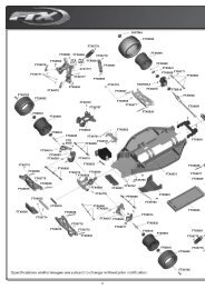
TOP GUN PARK FLITE EXTRA 330L SPARE PARTS LIST<br />
TGP0060 FUSELAGE SET<br />
TGP0061 MAIN WING SET<br />
TGP0062 HORIZONTAL TAIL<br />
TGP0063 VERTICAL TAIL FIN<br />
TGP0065 FRONT COWL<br />
TGP0066 MAIN UNDERCARRIDGE/SPATS<br />
TGP0067 GEARBOX<br />
TGP0068 PROPELLER<br />
TGP0069 SPINNER<br />
TGP0070 ACCESSORY PACK<br />
TGP0071 CONTROL RODS<br />
TGP0072 BIG GEAR SET<br />
TGP0073 ALLOY MOUNT/HEATSINK<br />
TGP0074 MOTOR BRACKET<br />
TGP0500 8G SERVO<br />
TGP0515 LI-PO WALL CHARGER<br />
TGP0515E LI-PO WALL CHARGER - EURO<br />
TGP0521 LI-PO BATTERY EXTRA 1500<br />
TGP0530 BRUSHLESS MOTOR 2040<br />
TGP0551 BRUSHLESS 25A ESC SPEED CONTROL<br />
DISTRIBUTORS OF QUALITY MODEL & HOBBY PRODUCTS<br />
Saxon House, Saxon Business Park, Hanbury Road, Bromsgrove, Worcestershire. B60 4AD. England<br />
Tel: +44 (0) 1527 575349 Fax: + 44 (0) 1527 570536<br />
E-mail: info@cmldistribution.co.uk<br />
Web site: www.cmldistribution.co.uk